EP2787431A1 - Electronic tag, electronic shelf labeling system, method of controlling electronic tag, and method of controlling electronic shelf labeling system - Google Patents
Electronic tag, electronic shelf labeling system, method of controlling electronic tag, and method of controlling electronic shelf labeling system Download PDFInfo
- Publication number
- EP2787431A1 EP2787431A1 EP13275144.7A EP13275144A EP2787431A1 EP 2787431 A1 EP2787431 A1 EP 2787431A1 EP 13275144 A EP13275144 A EP 13275144A EP 2787431 A1 EP2787431 A1 EP 2787431A1
- Authority
- EP
- European Patent Office
- Prior art keywords
- operating mode
- driving power
- electronic
- power information
- labeling system
- Prior art date
- Legal status (The legal status is an assumption and is not a legal conclusion. Google has not performed a legal analysis and makes no representation as to the accuracy of the status listed.)
- Withdrawn
Links
Images






Classifications
-
- G—PHYSICS
- G06—COMPUTING OR CALCULATING; COUNTING
- G06F—ELECTRIC DIGITAL DATA PROCESSING
- G06F3/00—Input arrangements for transferring data to be processed into a form capable of being handled by the computer; Output arrangements for transferring data from processing unit to output unit, e.g. interface arrangements
- G06F3/14—Digital output to display device ; Cooperation and interconnection of the display device with other functional units
- G06F3/147—Digital output to display device ; Cooperation and interconnection of the display device with other functional units using display panels
-
- G—PHYSICS
- G09—EDUCATION; CRYPTOGRAPHY; DISPLAY; ADVERTISING; SEALS
- G09F—DISPLAYING; ADVERTISING; SIGNS; LABELS OR NAME-PLATES; SEALS
- G09F3/00—Labels, tag tickets, or similar identification or indication means; Seals; Postage or like stamps
-
- G—PHYSICS
- G09—EDUCATION; CRYPTOGRAPHY; DISPLAY; ADVERTISING; SEALS
- G09G—ARRANGEMENTS OR CIRCUITS FOR CONTROL OF INDICATING DEVICES USING STATIC MEANS TO PRESENT VARIABLE INFORMATION
- G09G5/00—Control arrangements or circuits for visual indicators common to cathode-ray tube indicators and other visual indicators
-
- G—PHYSICS
- G09—EDUCATION; CRYPTOGRAPHY; DISPLAY; ADVERTISING; SEALS
- G09G—ARRANGEMENTS OR CIRCUITS FOR CONTROL OF INDICATING DEVICES USING STATIC MEANS TO PRESENT VARIABLE INFORMATION
- G09G2320/00—Control of display operating conditions
- G09G2320/04—Maintaining the quality of display appearance
- G09G2320/041—Temperature compensation
-
- G—PHYSICS
- G09—EDUCATION; CRYPTOGRAPHY; DISPLAY; ADVERTISING; SEALS
- G09G—ARRANGEMENTS OR CIRCUITS FOR CONTROL OF INDICATING DEVICES USING STATIC MEANS TO PRESENT VARIABLE INFORMATION
- G09G2330/00—Aspects of power supply; Aspects of display protection and defect management
- G09G2330/02—Details of power systems and of start or stop of display operation
- G09G2330/021—Power management, e.g. power saving
-
- G—PHYSICS
- G09—EDUCATION; CRYPTOGRAPHY; DISPLAY; ADVERTISING; SEALS
- G09G—ARRANGEMENTS OR CIRCUITS FOR CONTROL OF INDICATING DEVICES USING STATIC MEANS TO PRESENT VARIABLE INFORMATION
- G09G2380/00—Specific applications
- G09G2380/04—Electronic labels
Definitions
- the present invention relates to an electronic tag, an electronic shelf labeling system, a method of controlling an electronic tag, and a method of controlling an electronic shelf labeling system.
- ESL electronic shelf label
- an electronic tag using an electrophoretic display has characteristics very suitable for realizing high reflectivity and contrast ratios, and low levels of power consumption.
- the temperature range in which an electrophoretic display is usable is narrower than that of other display devices due to characteristics of materials of which electrophoretic displays are formed, such that there is a need to prevent image quality from deteriorating due to temperature changes.
- the electrophoretic display uses a temperature sensor to detect the temperature of the surrounding environment and keeps image quality relatively optimized, depending on the detected temperature.
- an electronic tag using an electrophoretic display needs to include a temperature sensor and determine an apparatus and a communication method capable of transferring the detected temperature to a control unit or a display unit.
- the electronic tag needs to perform a logical operation that refers to the feedbacked temperature value to determine an optimal operating mode. Further, the electronic tag requires driving power to perform the above-mentioned operation.
- the electronic shelf labeling system when the electronic shelf labeling system is applied to a retail store, the electronic shelf labeling system is used under the following environments.
- the use environment is a retail space in which consumer shopping is undertaken and a predetermined temperature range is maintained.
- an electronic tag using an electrophoretic display is mainly operated under the use environment conditions as described above. That is, despite that the temperature range for an electronic tag using an electrophoretic display may be previously known, there is a problem in that the temperature value is continuously detected using the temperature sensor.
- the following Related Art Document discloses an electronic shelf label and a method of controlling the same.
- the following Related Art Document provides a method of reducing battery consumption by changing a delay value between horizontal scanning lines of an image display depending on a temperature of a surrounding environment. That is, the following Related Art Document does not disclose setting an operating mode using a switch or being provided with the operating mode through communication, without the temperature sensor.
- An aspect of the present invention provides an electronic tag being provided with an operating mode depending on a switching operation or external communications and controlling driving power depending on the operating mode, without an existing temperature sensor.
- Another aspect of the present invention provides an electronic shelf labeling system using the proposed electronic tag, a method of controlling an electronic tag, and a method of controlling an electronic shelf labeling system.
- an electronic tag including: an operating mode setting unit setting an operating mode having at least two different temperature ranges; a control unit determining driving power information corresponding to the operating mode and controlling driving power depending on the determined driving power information; and a display unit displaying at least one of the driving power information and product information.
- the operating mode setting unit may include a switching unit performing a switching operation to set the operating mode.
- the operating mode setting unit may further include a communications unit that receives the operating mode externally supplied.
- the control unit may include a register in which the driving power information corresponding to the operating mode is stored.
- the display unit may include a register in which the driving power information corresponding to the operating mode is stored.
- the electronic tag may further include: a power supply unit supplying the driving power to the display unit depending on the control of the control unit.
- an electronic shelf labeling system including: a server being provided with an operating mode having at least two different temperature ranges externally supplied; and a plurality of electronic tags being provided with the operating mode from the server to control driving power depending on driving power information corresponding to the operating mode so as to display at least one of the driving power information and product information.
- the electronic shelf labeling system may further include: a plurality of gateways being provided with the operating mode from the server and providing the received operating mode to the plurality of electronic tags.
- the electronic shelf labeling system may further include: a user terminal providing the operating mode to the server.
- the plurality of electronic tags may include a communications unit being provided with the operating mode.
- the plurality of electronic tags may further include a switching unit performing a switching operation to set the operating mode.
- the plurality of electronic tags may further include a display unit displaying at least one of the driving power information and the product information.
- the plurality of electronic tags may further include a control unit controlling the driving power depending on the driving power information.
- the plurality of electronic tags may further include a power supply unit providing the driving power depending on the control of the control unit.
- the plurality of electronic tags may further include a register in which the driving power information is stored.
- a method of controlling an electronic tag including: setting an operating mode having at least two different temperature ranges; determining driving power information corresponding to the operating mode; controlling driving power depending on the driving power information; and displaying at least one of the driving power information and product information.
- the setting of the operating mode may include performing a switching operation to set the operating mode.
- the setting of the operating mode may include being provided with the operating mode externally supplied.
- a method of controlling an electronic shelf labeling system including: allowing an operating mode having at least two different temperature ranges externally supplied to be provided to a server, to then provide the received operating mode to a plurality of gateways; providing, by the plurality of gateways, the operating mode to the plurality of electronic tags; controlling, by the plurality of electronic tags, to control driving power depending on driving power information corresponding to the operating mode; and displaying, using the plurality of electronic tags, at least one of the driving power information and product information.
- the method of controlling an electronic shelf labeling system may further include: providing, by a user terminal, the operating mode to the server.
- the method of controlling an electronic shelf labeling system may further include: directly providing, by the server, the operating mode to the plurality of electronic tags.
- the method of controlling an electronic shelf labeling system may further include: performing, by the plurality of electronic tags, a switching operation to set the operating mode.
- FIG. 1 is a block diagram of an electronic tag 100 according to an embodiment of the present invention.
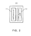
- FIG. 2 is a block diagram of an operating mode setting unit 110 according to an embodiment of the present invention.
- the electronic tag 100 may include an operating mode setting unit 110, a control unit 120, a display unit 130, and a power supply unit 140.
- the operating mode setting unit 110 may set an operating mode and provide the set operating mode to the control unit 120.
- the operating mode may have at least two different temperature ranges.
- the operating mode setting unit 110 is one embodiment for setting an operating mode and may include a switching unit 111 and a communications unit 112.
- the operating mode setting unit 110 may include the switching unit 111 and may set the operating mode through the switching operation in the switching unit 111.
- the switching unit 111 may include at least one switch, and as one embodiment of the present invention, the switch may simply be two selective switches and may also be three selective switches.
- any type of switch may be used without being limited in terms of the usage or form thereof.
- the reason is that the operating mode of the electronic tag 100 may be set depending on the use environment in which the electronic tag 100 is used, and thus the type of required switch may be changed.
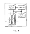
- FIG. 3 is a block diagram of the electronic tag in which the switching unit 111 and the communications unit 112 are included in the operating mode setting unit 110.
- the operating mode setting unit 110 may receive the operating mode externally supplied. That is, the operating mode setting unit 110 may further include the communications unit 112 that receives the operating mode through external communications.
- the communications unit 112 may receive the operating mode externally supplied and may provide the operating mode to the control unit 120.
- the control unit 120 may determine driving power information corresponding to the operating mode to control the driving power depending on the driving power information.
- the control unit 120 may determine the driving power information corresponding to the operating mode. Further, the driving power may be controlled depending on the determined driving power information. In more detail, the control unit 120 may receive the operating mode set by the switching operation of the switching unit 111 or may receive the operating mode that has been provided to the communications unit 112 through the external communications.
- control unit 120 may control the driving power depending on the driving power information corresponding to the operating mode.
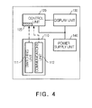
- FIG. 4 is a block diagram of the electronic tag 100 in which a register 125 is included in the control unit 120 of FIG. 1 .
- the driving power information may be stored in the register 125 and the register 125 may be included in the control unit 120.
- the driving power information indicates the information on the driving power that is to be controlled depending on the operating mode.
- control unit 120 may control the driving power supplied to the display unit 130 depending on the driving power information pre-stored in the register and corresponding to the operating mode.
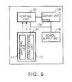
- FIG. 5 is a block diagram of the electronic tag 100 in which a register 135 is included in the display unit 130 of FIG. 1 .
- the register 135 in which the driving power information is stored may be included in the display unit 130. Therefore, the control unit 120 receives the driving power information corresponding to the operating mode from the display unit 130, and thus may control the driving power.
- the display unit 130 may output at least one of the driving power information and product information.
- the control unit 120 may control the driving power to keep the image quality of the display unit 130 stable.
- the display unit 130 may output the operating mode set by the operating mode setting unit 110 on a screen. This will be described below with reference to FIG. 7 .
- the power supply unit 140 may supply the driving power to the display unit 130 depending on the control of the control unit 120.
- the control unit 120 may control the driving power depending on the driving power information corresponding to the operating mode.
- the operating mode setting will be described for example.
- FIG. 6A is a graph illustrating a change in driving power depending on temperature. Referring to FIG. 6A ,in a case in which materials of electrophoretic displays configuring the screens of the electronic tags 100 are the same, detailed deviations may be displayed on the screens of the electronic tags 100, but substantially, a tendency as illustrated in a graph of FIG. 6A is provided.
- the electronic shelf labeling system when the electronic shelf labeling system is applied in a retail store, the electronic shelf labeling system may be operated under the following environmental conditions.
- the use environment is a retail space in which consumer shopping is undertaken and a predetermined temperature range is maintained.
- Special products, such as refrigerated foods, are also kept at a low temperature within a predetermined temperature range.
- the temperature sensor does not have to continuously sense the change in temperature, such that the operating mode may be set in advance or set while operating, depending on the temperature range corresponding to the use environment.
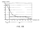
- FIG. 6B is a diagram illustrating a manner in which a temperature range in a graph of FIG. 6A is divided into two.
- FIG. 6B is a graph illustrating respective temperature ranges when the operating mode of the electronic tag 100 is divided into a refrigerating mode 610 and a room temperature mode 620, as one embodiment of the present invention.
- the operating mode setting unit 110 may set the operating mode to the refrigerating mode 610 or the room temperature mode 620. That is, the switching unit 111 may perform the switching operation to set the operating mode to the refrigerating mode 610 or the room temperature mode 620. Alternatively, the communications unit 112 may receive the operating mode externally supplied. Herein, it is assumed that the operating mode is, for example, the refrigerating mode 610.
- the control unit 120 may receive the driving power information corresponding to the refrigerating mode 610.
- the control unit 120 since the control unit 120 includes the register 125, the control unit 120 may receive the driving power information corresponding to the refrigerating mode 610 from the register 125 within the control unit 120.
- the control unit 130 since the display unit 130 includes the register 135, the control unit 130 may receive the driving power information corresponding to the refrigerating mode 610 from the register 135 within the display unit 130.
- the control unit 120 being provided with the driving power information may control the driving power supplied to the display unit 130 depending on the driving power information corresponding to the refrigerating mode 610.
- the display unit 120 of the electronic tag 100 requires the driving power depending on the room temperature mode 620.
- the control unit 120 may receive the driving power information corresponding to the room temperature mode 620, stored in one of the register 125 within the control unit 120 and the register 135 within the display unit 130.
- the driving power to be supplied to the display unit 130 may be controlled depending on the driving power information.
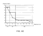
- FIG. 6C is a diagram illustrating a manner in which a temperature range in the graph of FIG. 6A is divided into three.
- FIG. 6C corresponds to the case in which the use environment is divided into three.
- the type of switch of the operating mode setting unit 110 may be determined in three selective types.
- the room temperature mode 620 may be divided into a first room temperature mode 621 and a second room temperature mode 622, and the control unit 120 may determine the driving power information corresponding to each condition to control the driving power supplied to the display unit 130.
- FIG. 7 illustrates the display unit 130 of the electronic tag that displays product information 710 and an operating mode 720 according to the embodiment of the present invention.
- the display unit 130 may output product information to a customer as the product information 710 and may also display the operating mode 720 set by the operating mode setting unit 110. Therefore, the user may look the operating mode 720 displayed on the display unit 130 to more effectively manage the electronic tag 100.
- the display of the product information 710 or the operating mode 720 may be visually transferred to a manager or a customer through a variety of representation ways, such as figures, symbols, special symbols, and the like, and thus, these representation ways are not limited to the embodiment described in FIG. 7 .
- the electronic tag 100 may determine the operating mode of the electronic tag 100 by a simple switching operation, without the temperature sensor and may also receive the operating mode externally supplied. By doing so, the characteristics of the image quality displayed on the display unit 130 of the electronic tag 100 may be stably maintained.
- FIG. 8 is a block diagram of an electronic shelf labeling system according to an embodiment of the present invention.
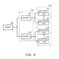
- FIG. 9 is a block diagram of an electronic shelf labeling system according to another embodiment of the present invention.
- the electronic shelf labeling system may include a server 800 and a plurality of electronic tags 900.
- the electronic shelf labeling system may include the server 800, a plurality of gateways 850, and the plurality of electronic tags 900.
- the server 500 may provide the operating mode having the at least two different temperature ranges externally supplied.
- the provided method may be at least one of wireless and wired communications.
- the electronic shelf labeling system may further include a user terminal that provides the operating mode having the at least two different temperature ranges externally supplied.
- the user terminal may set the operating mode and provide the set operating mode to the server 800, and the server 800 may provide the received operating mode to the plurality of electronic tags 900.
- the plurality of electronic tags 900 may receive the operating mode to control the driving power depending on the driving power information corresponding to the operating mode. Alternatively, the plurality of electronic tags 900 may perform the switching operation to set the operating mode. After the setting of the operating mode, the plurality of electronic tags 900 may control the driving power and may display at least one of the driving power information and the product information on the screen.
- the server 800 may form a network together with the plurality of gateways 850 and the plurality of electronic tags 900 may be connected to the plurality of gateways 850.
- the plurality of electronic tags 910 and 920 may be connected to the gateway 851, and the gateway 851 may also be connected to the server 800 to form a network.
- the server 800 may directly provide the operating mode to the plurality of electronic tags 900, and may provide the operating mode to the plurality of gateways 850.
- the plurality of gateways 850 may provide the received operating mode to the plurality of electronic tags 900.
- the operating mode may be provided to the communications units 112 of the plurality of electronic tags 900, and the plurality of electronic tags 900 may control the driving power depending on the driving power information corresponding to the operating mode.
- the plurality of electronic tags 900 may set the operating mode by the switching operation of the switching unit 111.
- the communications unit 112 may receive the operating mode from one of the server 800 and the plurality of gateways 850.
- the plurality of electronic tags 900 may include the registers 125 and 135 in which the driving power information corresponding to the operating mode is stored and may also include the control unit 120 controlling the driving power depending on the driving power information.
- the plurality of electronic tags 900 may further include the power supply unit 140 that supplies the driving power depending on the control of the control unit 120 and may include the display unit 130 that displays at least one of the driving power information and the product information.
- the power supply unit 140 that supplies the driving power depending on the control of the control unit 120
- the display unit 130 that displays at least one of the driving power information and the product information.
- respective components of the plurality of electronic tags 900 are the same as the afore-described components, and therefore, detailed descriptions thereof will be excluded.
- FIG. 10 is a flow chart of a method of controlling an electronic tag according to the embodiment of the present invention.
- a method of controlling an electronic tag may include setting the operating mode having two different temperature ranges (S110), determining the driving power information corresponding to the operating mode (S120), controlling the driving power depending on the driving power information (S130), and displaying at least one of the driving power information and the product information (S140).
- FIG. 11 is a flow chart of a method of controlling an electronic tag according to another embodiment of the present invention.
- the setting of the operating mode may be performing the switching operation to set the operating mode (S111) or may be that the operating mode externally supplied is provided (S112). Processes after being provided with the operating mode are the same as one described with reference to FIG. 10 , and therefore the description thereof will be omitted.
- FIG. 12 is a flow chart of a method of controlling an electronic shelf labeling system according to an embodiment of the present invention.
- FIG. 13 is a flow chart of a method of controlling an electronic shelf labeling system according to another embodiment of the present invention.
- the method of controlling an electronic shelf labeling system may include allowing the operating mode having the at least two different temperature ranges externally supplied to be provided to the server to then provide the received operating mode to the plurality of gateways (S210), providing, by the plurality of gateways, the operating mode to the plurality of electronic tags (S220), controlling, by the plurality of electronic tags, the driving power depending on the driving power information corresponding to the operating mode (S230), and displaying, using the plurality of electronic tags, at least one of the driving power information and the product information (S240).
- the method of controlling an electronic shelf labeling system may include providing, by the user terminal, the operating mode to the server (S205). Further, the method of controlling an electronic shelf labeling system may further include providing, by the server, the operating mode having the at least two different temperature ranges to the plurality of electronic tags (S210).
- the server may provide the operating mode provided from the user terminal to the plurality of electronic tags through the plurality of gateways (S210) or may directly provide the operating mode to the plurality of electronic tags (S215).
- the method of controlling an electronic shelf labeling system may include setting the operating mode by performing the switching operation without being provided with the operating mode externally supplied (S225).
- the temperature sensor may not be used, such that manufacturing costs may be saved, and the connection lines connecting the information acquired by the temperature sensor to the control unit and the input ports of the control unit may be saved.
- the current consumption consumed by the temperature sensor may be saved and the communication time and the driving power consumption consumed during the process of transferring the temperature value detected by the temperature sensor to the control unit may be saved. Further, the costs may be saved by not using the temperature sensor.
Landscapes
- Engineering & Computer Science (AREA)
- Theoretical Computer Science (AREA)
- Physics & Mathematics (AREA)
- General Physics & Mathematics (AREA)
- Human Computer Interaction (AREA)
- General Engineering & Computer Science (AREA)
- Computer Hardware Design (AREA)
- Control Of Indicators Other Than Cathode Ray Tubes (AREA)
- Cash Registers Or Receiving Machines (AREA)
- Display Racks (AREA)
Abstract
There are provided an electronic tag, an electronic shelf labeling system, a method of controlling an electronic tag, and a method of controlling an electronic shelf labeling system. The electronic tag includes an operating mode setting unit setting an operating mode having at least two different temperature ranges, a control unit determining driving power information corresponding to the operating mode and controlling driving power depending on the determined driving power information, and a display unit displaying at least one of the driving power information and product information.
Description
- This application claims the priority of Korean Patent Application No.
10-2013-0035062 filed on April 1, 2013 - The present invention relates to an electronic tag, an electronic shelf labeling system, a method of controlling an electronic tag, and a method of controlling an electronic shelf labeling system.
- In recent times, research into and development of an electronic shelf label (ESL) system have been actively conducted.
- Meanwhile, among components of the electronic shelf labeling system, an electronic tag using an electrophoretic display (EPD) has characteristics very suitable for realizing high reflectivity and contrast ratios, and low levels of power consumption.
- On the other hand, the temperature range in which an electrophoretic display is usable is narrower than that of other display devices due to characteristics of materials of which electrophoretic displays are formed, such that there is a need to prevent image quality from deteriorating due to temperature changes.
- In order to improve on the above-mentioned problems, the electrophoretic display uses a temperature sensor to detect the temperature of the surrounding environment and keeps image quality relatively optimized, depending on the detected temperature.
- That is, an electronic tag using an electrophoretic display needs to include a temperature sensor and determine an apparatus and a communication method capable of transferring the detected temperature to a control unit or a display unit. In addition, the electronic tag needs to perform a logical operation that refers to the feedbacked temperature value to determine an optimal operating mode. Further, the electronic tag requires driving power to perform the above-mentioned operation.
- However, when the electronic shelf labeling system is applied to a retail store, the electronic shelf labeling system is used under the following environments.
- 1) The use environment is a retail space in which consumer shopping is undertaken and a predetermined temperature range is maintained.
- 2) Special products, such as refrigerated foods, are also kept at a low temperature within a predetermined temperature range.
- Therefore, among the components of an electronic shelf labeling system, an electronic tag using an electrophoretic display is mainly operated under the use environment conditions as described above. That is, despite that the temperature range for an electronic tag using an electrophoretic display may be previously known, there is a problem in that the temperature value is continuously detected using the temperature sensor.
- The following Related Art Document discloses an electronic shelf label and a method of controlling the same. The following Related Art Document provides a method of reducing battery consumption by changing a delay value between horizontal scanning lines of an image display depending on a temperature of a surrounding environment. That is, the following Related Art Document does not disclose setting an operating mode using a switch or being provided with the operating mode through communication, without the temperature sensor.
- Korean Patent Laid-Open Publication No.
10-2012-0077948 - An aspect of the present invention provides an electronic tag being provided with an operating mode depending on a switching operation or external communications and controlling driving power depending on the operating mode, without an existing temperature sensor. Another aspect of the present invention provides an electronic shelf labeling system using the proposed electronic tag, a method of controlling an electronic tag, and a method of controlling an electronic shelf labeling system.
- According to an aspect of the present invention, there is provided an electronic tag, including: an operating mode setting unit setting an operating mode having at least two different temperature ranges; a control unit determining driving power information corresponding to the operating mode and controlling driving power depending on the determined driving power information; and a display unit displaying at least one of the driving power information and product information.
- The operating mode setting unit may include a switching unit performing a switching operation to set the operating mode.
- The operating mode setting unit may further include a communications unit that receives the operating mode externally supplied.
- The control unit may include a register in which the driving power information corresponding to the operating mode is stored.
- The display unit may include a register in which the driving power information corresponding to the operating mode is stored.
- The electronic tag may further include: a power supply unit supplying the driving power to the display unit depending on the control of the control unit.
- According to an aspect of the present invention, there is provided an electronic shelf labeling system, including: a server being provided with an operating mode having at least two different temperature ranges externally supplied; and a plurality of electronic tags being provided with the operating mode from the server to control driving power depending on driving power information corresponding to the operating mode so as to display at least one of the driving power information and product information.
- The electronic shelf labeling system may further include: a plurality of gateways being provided with the operating mode from the server and providing the received operating mode to the plurality of electronic tags.
- The electronic shelf labeling system may further include: a user terminal providing the operating mode to the server.
- The plurality of electronic tags may include a communications unit being provided with the operating mode.
- The plurality of electronic tags may further include a switching unit performing a switching operation to set the operating mode.
- The plurality of electronic tags may further include a display unit displaying at least one of the driving power information and the product information.
- The plurality of electronic tags may further include a control unit controlling the driving power depending on the driving power information.
- The plurality of electronic tags may further include a power supply unit providing the driving power depending on the control of the control unit.
- The plurality of electronic tags may further include a register in which the driving power information is stored.
- According to an aspect of the present invention, there is provided a method of controlling an electronic tag, including: setting an operating mode having at least two different temperature ranges; determining driving power information corresponding to the operating mode; controlling driving power depending on the driving power information; and displaying at least one of the driving power information and product information.
- The setting of the operating mode may include performing a switching operation to set the operating mode.
- The setting of the operating mode may include being provided with the operating mode externally supplied.
- According to an aspect of the present invention, there is provided a method of controlling an electronic shelf labeling system, including: allowing an operating mode having at least two different temperature ranges externally supplied to be provided to a server, to then provide the received operating mode to a plurality of gateways; providing, by the plurality of gateways, the operating mode to the plurality of electronic tags; controlling, by the plurality of electronic tags, to control driving power depending on driving power information corresponding to the operating mode; and displaying, using the plurality of electronic tags, at least one of the driving power information and product information.
- The method of controlling an electronic shelf labeling system may further include: providing, by a user terminal, the operating mode to the server.
- The method of controlling an electronic shelf labeling system may further include: directly providing, by the server, the operating mode to the plurality of electronic tags.
- The method of controlling an electronic shelf labeling system may further include: performing, by the plurality of electronic tags, a switching operation to set the operating mode.
- The above and other aspects, features and other advantages of the present invention will be more clearly understood from the following detailed description taken in conjunction with the accompanying drawings, in which:
-
FIG. 1 is a block diagram of an electronic tag according to an embodiment of the present invention; -
FIG. 2 is a block diagram of an operating mode setting unit according to an embodiment of the present invention; -
FIG. 3 is a block diagram of the electronic tag in which a switching unit and a communications unit are included in the operating mode setting unit; -
FIG. 4 is a block diagram of the electronic tag in which a register is included in the control unit ofFIG. 1 ; -
FIG. 5 is a block diagram of the electronic tag in which the register is included in the display unit ofFIG. 1 ; -
FIG. 6A is a graph illustrating a change in driving power depending on temperature; -
FIG. 6B is a diagram illustrating a manner in which a temperature range is divided into two in a graph; -
FIG. 6C is a diagram illustrating a manner in which a temperature range is divided into three in the graph ofFIG. 6A ; -
FIG. 7 is a diagram illustrating the electronic tag displaying product information and an operating mode according to the embodiment of the present invention; -
FIG. 8 is a block diagram of an electronic shelf labeling system according to an embodiment of the present invention; -
FIG. 9 is a block diagram of an electronic shelf labeling system according to another embodiment of the present invention; -
FIG. 10 is a flow chart of a method of controlling an electronic tag according to the embodiment of the present invention; -
FIG. 11 is a flow chart of a method of controlling an electronic tag according to another embodiment of the present invention; -
FIG. 12 is a flow chart of a method of controlling an electronic shelf labeling system according to an embodiment of the present invention; and -
FIG. 13 is a flow chart of a method of controlling an electronic shelf labeling system according to another embodiment of the present invention. - Hereinafter, embodiments of the present invention will be described in detail with reference to the accompanying drawings. The invention may, however, be embodied in many different forms and should not be construed as being limited to the embodiments set forth herein.
- Rather, these embodiments are provided so that this disclosure will be thorough and complete, and will fully convey the scope of the invention to those skilled in the art.
-
FIG. 1 is a block diagram of an electronic tag 100 according to an embodiment of the present invention. -
FIG. 2 is a block diagram of an operatingmode setting unit 110 according to an embodiment of the present invention. - Referring to
FIGS. 1 and2 , the electronic tag 100 may include an operatingmode setting unit 110, acontrol unit 120, adisplay unit 130, and apower supply unit 140. - The operating
mode setting unit 110 may set an operating mode and provide the set operating mode to thecontrol unit 120. In this case, the operating mode may have at least two different temperature ranges. - In addition, the operating
mode setting unit 110 is one embodiment for setting an operating mode and may include aswitching unit 111 and acommunications unit 112. - A fact that the operating
mode setting unit 110 sets the operating mode by a switching operation will be first described. - The operating
mode setting unit 110 may include theswitching unit 111 and may set the operating mode through the switching operation in theswitching unit 111. In this configuration, theswitching unit 111 may include at least one switch, and as one embodiment of the present invention, the switch may simply be two selective switches and may also be three selective switches. - That is, as long as the switch included in the
switching unit 111 performs a switching operation, any type of switch may be used without being limited in terms of the usage or form thereof. The reason is that the operating mode of the electronic tag 100 may be set depending on the use environment in which the electronic tag 100 is used, and thus the type of required switch may be changed. -
FIG. 3 is a block diagram of the electronic tag in which theswitching unit 111 and thecommunications unit 112 are included in the operatingmode setting unit 110. - Referring to
FIG. 3 , the operatingmode setting unit 110 may receive the operating mode externally supplied. That is, the operatingmode setting unit 110 may further include thecommunications unit 112 that receives the operating mode through external communications. - Therefore, the
communications unit 112 may receive the operating mode externally supplied and may provide the operating mode to thecontrol unit 120. As described above, thecontrol unit 120 may determine driving power information corresponding to the operating mode to control the driving power depending on the driving power information. - The
control unit 120 may determine the driving power information corresponding to the operating mode. Further, the driving power may be controlled depending on the determined driving power information. In more detail, thecontrol unit 120 may receive the operating mode set by the switching operation of theswitching unit 111 or may receive the operating mode that has been provided to thecommunications unit 112 through the external communications. - In this case, the
control unit 120 may control the driving power depending on the driving power information corresponding to the operating mode. -
FIG. 4 is a block diagram of the electronic tag 100 in which aregister 125 is included in thecontrol unit 120 ofFIG. 1 . Referring toFIG. 4 , the driving power information may be stored in theregister 125 and theregister 125 may be included in thecontrol unit 120. - Herein, the driving power information indicates the information on the driving power that is to be controlled depending on the operating mode.
- That is, in the operating
mode setting unit 110, when the operating mode is set by the switching operation of theswitching unit 111 or thecommunications unit 112 receives the operating mode externally supplied, thecontrol unit 120 may control the driving power supplied to thedisplay unit 130 depending on the driving power information pre-stored in the register and corresponding to the operating mode. -
FIG. 5 is a block diagram of the electronic tag 100 in which aregister 135 is included in thedisplay unit 130 ofFIG. 1 . Referring toFIG. 5 , theregister 135 in which the driving power information is stored may be included in thedisplay unit 130. Therefore, thecontrol unit 120 receives the driving power information corresponding to the operating mode from thedisplay unit 130, and thus may control the driving power. - The
display unit 130 may output at least one of the driving power information and product information. At this time, thecontrol unit 120 may control the driving power to keep the image quality of thedisplay unit 130 stable. - Further, for user convenience, the
display unit 130 may output the operating mode set by the operatingmode setting unit 110 on a screen. This will be described below with reference toFIG. 7 . - The
power supply unit 140 may supply the driving power to thedisplay unit 130 depending on the control of thecontrol unit 120. Thecontrol unit 120 may control the driving power depending on the driving power information corresponding to the operating mode. - The operating mode setting will be described for example.
-
FIG. 6A is a graph illustrating a change in driving power depending on temperature. Referring toFIG. 6A ,in a case in which materials of electrophoretic displays configuring the screens of the electronic tags 100 are the same, detailed deviations may be displayed on the screens of the electronic tags 100, but substantially, a tendency as illustrated in a graph ofFIG. 6A is provided. - This indicates that the
display unit 130 needs to supply the driving power corresponding to the temperature so as to keep the same image quality despite the difference in temperature. - However, as described above, when the electronic shelf labeling system is applied in a retail store, the electronic shelf labeling system may be operated under the following environmental conditions.
- 1) The use environment is a retail space in which consumer shopping is undertaken and a predetermined temperature range is maintained. 2) Special products, such as refrigerated foods, are also kept at a low temperature within a predetermined temperature range.
- That is, since the environment in which the electronic shelf labeling system is used may be known in advance at the time at which the electronic shelf labeling system is installed, the temperature sensor does not have to continuously sense the change in temperature, such that the operating mode may be set in advance or set while operating, depending on the temperature range corresponding to the use environment.
-
FIG. 6B is a diagram illustrating a manner in which a temperature range in a graph ofFIG. 6A is divided into two.FIG. 6B is a graph illustrating respective temperature ranges when the operating mode of the electronic tag 100 is divided into a refrigeratingmode 610 and aroom temperature mode 620, as one embodiment of the present invention. - In more detail, the operating
mode setting unit 110 may set the operating mode to the refrigeratingmode 610 or theroom temperature mode 620. That is, theswitching unit 111 may perform the switching operation to set the operating mode to the refrigeratingmode 610 or theroom temperature mode 620. Alternatively, thecommunications unit 112 may receive the operating mode externally supplied. Herein, it is assumed that the operating mode is, for example, the refrigeratingmode 610. - After the operating mode is set to be the refrigerating
mode 610, thecontrol unit 120 may receive the driving power information corresponding to the refrigeratingmode 610. Referring toFIG. 4 , since thecontrol unit 120 includes theregister 125, thecontrol unit 120 may receive the driving power information corresponding to the refrigeratingmode 610 from theregister 125 within thecontrol unit 120. In the case of referring toFIG. 5 , as another embodiment of the present invention, since thedisplay unit 130 includes theregister 135, thecontrol unit 130 may receive the driving power information corresponding to the refrigeratingmode 610 from theregister 135 within thedisplay unit 130. - The
control unit 120 being provided with the driving power information may control the driving power supplied to thedisplay unit 130 depending on the driving power information corresponding to the refrigeratingmode 610. - For example, when the operating mode is determined as the
room temperature mode 620, referring toFIG. 6B , thedisplay unit 120 of the electronic tag 100 requires the driving power depending on theroom temperature mode 620. In this case, thecontrol unit 120 may receive the driving power information corresponding to theroom temperature mode 620, stored in one of theregister 125 within thecontrol unit 120 and theregister 135 within thedisplay unit 130. The driving power to be supplied to thedisplay unit 130 may be controlled depending on the driving power information. -
FIG. 6C is a diagram illustrating a manner in which a temperature range in the graph ofFIG. 6A is divided into three. - That is, unlike
FIG. 6B ,FIG. 6C corresponds to the case in which the use environment is divided into three. In this case, the type of switch of the operatingmode setting unit 110 may be determined in three selective types. - For example, the
room temperature mode 620 may be divided into a firstroom temperature mode 621 and a secondroom temperature mode 622, and thecontrol unit 120 may determine the driving power information corresponding to each condition to control the driving power supplied to thedisplay unit 130. -
FIG. 7 illustrates thedisplay unit 130 of the electronic tag that displaysproduct information 710 and anoperating mode 720 according to the embodiment of the present invention. - That is, the
display unit 130 may output product information to a customer as theproduct information 710 and may also display the operatingmode 720 set by the operatingmode setting unit 110. Therefore, the user may look theoperating mode 720 displayed on thedisplay unit 130 to more effectively manage the electronic tag 100. - In this case, the display of the
product information 710 or the operatingmode 720 may be visually transferred to a manager or a customer through a variety of representation ways, such as figures, symbols, special symbols, and the like, and thus, these representation ways are not limited to the embodiment described inFIG. 7 . - By doing so, the electronic tag 100 may determine the operating mode of the electronic tag 100 by a simple switching operation, without the temperature sensor and may also receive the operating mode externally supplied. By doing so, the characteristics of the image quality displayed on the
display unit 130 of the electronic tag 100 may be stably maintained. -
FIG. 8 is a block diagram of an electronic shelf labeling system according to an embodiment of the present invention. -
FIG. 9 is a block diagram of an electronic shelf labeling system according to another embodiment of the present invention. - Referring to
FIG. 8 , the electronic shelf labeling system may include aserver 800 and a plurality ofelectronic tags 900. - Further, referring to
FIG. 9 , the electronic shelf labeling system may include theserver 800, a plurality ofgateways 850, and the plurality ofelectronic tags 900. - The server 500 may provide the operating mode having the at least two different temperature ranges externally supplied. In this case, the provided method may be at least one of wireless and wired communications.
- Further, the electronic shelf labeling system may further include a user terminal that provides the operating mode having the at least two different temperature ranges externally supplied.
- That is, the user terminal may set the operating mode and provide the set operating mode to the
server 800, and theserver 800 may provide the received operating mode to the plurality ofelectronic tags 900. - The plurality of
electronic tags 900 may receive the operating mode to control the driving power depending on the driving power information corresponding to the operating mode. Alternatively, the plurality ofelectronic tags 900 may perform the switching operation to set the operating mode. After the setting of the operating mode, the plurality ofelectronic tags 900 may control the driving power and may display at least one of the driving power information and the product information on the screen. - In addition, the
server 800 may form a network together with the plurality ofgateways 850 and the plurality ofelectronic tags 900 may be connected to the plurality ofgateways 850. - Referring to
FIG. 9 , the plurality ofelectronic tags gateway 851, and thegateway 851 may also be connected to theserver 800 to form a network. - In this case, the
server 800 may directly provide the operating mode to the plurality ofelectronic tags 900, and may provide the operating mode to the plurality ofgateways 850. For example, when theserver 800 provides the operating mode to the plurality ofgateways 850, the plurality ofgateways 850 may provide the received operating mode to the plurality ofelectronic tags 900. - In this case, the operating mode may be provided to the
communications units 112 of the plurality ofelectronic tags 900, and the plurality ofelectronic tags 900 may control the driving power depending on the driving power information corresponding to the operating mode. - Meanwhile, the plurality of
electronic tags 900 may set the operating mode by the switching operation of theswitching unit 111. Alternatively, thecommunications unit 112 may receive the operating mode from one of theserver 800 and the plurality ofgateways 850. - After the operating mode is set, the plurality of
electronic tags 900 may include theregisters control unit 120 controlling the driving power depending on the driving power information. - In addition, the plurality of
electronic tags 900 may further include thepower supply unit 140 that supplies the driving power depending on the control of thecontrol unit 120 and may include thedisplay unit 130 that displays at least one of the driving power information and the product information. In this case, respective components of the plurality ofelectronic tags 900 are the same as the afore-described components, and therefore, detailed descriptions thereof will be excluded. -
FIG. 10 is a flow chart of a method of controlling an electronic tag according to the embodiment of the present invention. - Referring to
FIG. 10 , a method of controlling an electronic tag may include setting the operating mode having two different temperature ranges (S110), determining the driving power information corresponding to the operating mode (S120), controlling the driving power depending on the driving power information (S130), and displaying at least one of the driving power information and the product information (S140). -
FIG. 11 is a flow chart of a method of controlling an electronic tag according to another embodiment of the present invention. - Referring to
FIG. 11 , the setting of the operating mode (S110) may be performing the switching operation to set the operating mode (S111) or may be that the operating mode externally supplied is provided (S112). Processes after being provided with the operating mode are the same as one described with reference toFIG. 10 , and therefore the description thereof will be omitted. -
FIG. 12 is a flow chart of a method of controlling an electronic shelf labeling system according to an embodiment of the present invention. -
FIG. 13 is a flow chart of a method of controlling an electronic shelf labeling system according to another embodiment of the present invention. - Referring to
FIG. 12 , the method of controlling an electronic shelf labeling system may include allowing the operating mode having the at least two different temperature ranges externally supplied to be provided to the server to then provide the received operating mode to the plurality of gateways (S210), providing, by the plurality of gateways, the operating mode to the plurality of electronic tags (S220), controlling, by the plurality of electronic tags, the driving power depending on the driving power information corresponding to the operating mode (S230), and displaying, using the plurality of electronic tags, at least one of the driving power information and the product information (S240). - Referring to
FIG. 13 , the method of controlling an electronic shelf labeling system may include providing, by the user terminal, the operating mode to the server (S205). Further, the method of controlling an electronic shelf labeling system may further include providing, by the server, the operating mode having the at least two different temperature ranges to the plurality of electronic tags (S210). - That is, referring to
FIGS. 12 and13 , the server may provide the operating mode provided from the user terminal to the plurality of electronic tags through the plurality of gateways (S210) or may directly provide the operating mode to the plurality of electronic tags (S215). In addition, the method of controlling an electronic shelf labeling system may include setting the operating mode by performing the switching operation without being provided with the operating mode externally supplied (S225). - Further, in the embodiment of the present invention, the temperature sensor may not be used, such that manufacturing costs may be saved, and the connection lines connecting the information acquired by the temperature sensor to the control unit and the input ports of the control unit may be saved.
- As set forth above, according to the embodiments of the present invention, the current consumption consumed by the temperature sensor may be saved and the communication time and the driving power consumption consumed during the process of transferring the temperature value detected by the temperature sensor to the control unit may be saved. Further, the costs may be saved by not using the temperature sensor.
- While the present invention has been shown and described in connection with the embodiments, it will be apparent to those skilled in the art that modifications and variations can be made without departing from the spirit and scope of the invention as defined by the appended claims.
Claims (18)
- An electronic tag, comprising:an operating mode setting unit setting an operating mode having at least two different temperature ranges;a control unit determining driving power information corresponding to the operating mode and controlling driving power depending on the determined driving power information; anda display unit displaying at least one of the driving power information and product information.
- The electronic tag of claim 1, wherein the operating mode setting unit includes
a switching unit performing a switching operation to set the operating mode, and
a communications unit that receives the operating mode externally supplied. - The electronic tag of claim 1, wherein the control unit includes a register in which the driving power information corresponding to the operating mode is stored.
- The electronic tag of claim 1, wherein the display unit includes a register in which the driving power information corresponding to the operating mode is stored.
- The electronic tag of claim 1, further comprising a power supply unit supplying the driving power to the display unit depending on the control of the control unit.
- An electronic shelf labeling system, comprising:a server being provided with an operating mode having at least two different temperature ranges externally supplied; anda plurality of electronic tags being provided with the operating mode from the server to control driving power depending on driving power information corresponding to the operating mode so as to display at least one of the driving power information and product information.
- The electronic shelf labeling system of claim 6, further comprising a plurality of gateways being provided with the operating mode from the server and providing the received operating mode to the plurality of electronic tags.
- The electronic shelf labeling system of claim 6, further comprising a user terminal providing the operating mode to the server.
- The electronic shelf labeling system of claim 6, wherein the plurality of electronic tags include a communications unit being provided with the operating mode, a switching unit performing a switching operation to set the operating mode, a display unit displaying at least one of the driving power information and the product information, and a register in which the driving power information is stored.
- The electronic shelf labeling system of claim 6, wherein the plurality of electronic tags further include a control unit controlling the driving power depending on the driving power information.
- The electronic shelf labeling system of claim 10, wherein the plurality of electronic tags further include a power supply unit providing the driving power depending on the control of the control unit.
- A method of controlling an electronic tag, comprising:setting an operating mode having at least two different temperature ranges;determining driving power information corresponding to the operating mode;controlling driving power depending on the driving power information; anddisplaying at least one of the driving power information and product information.
- The method of claim 12, wherein the setting of the operating mode includes performing a switching operation to set the operating mode.
- The method of claim 12, wherein the setting of the operating mode includes being provided with the operating mode externally supplied.
- A method of controlling an electronic shelf labeling system, comprising:allowing an operating mode having at least two different temperature ranges externally supplied to be provided to a server to then provide the received operating mode to a plurality of gateways;providing, by the plurality of gateways, the operating mode to the plurality of electronic tags;controlling, by the plurality of electronic tags, to control driving power depending on driving power information corresponding to the operating mode; anddisplaying, using the plurality of electronic tags, at least one of the driving power information and product information.
- The method of claim 15, further comprising providing, by a user terminal, the operating mode to the server.
- The method of claim 15, further comprising directly providing, by the server, the operating mode to the plurality of electronic tags.
- The method of claim 15 further comprising performing, by the plurality of electronic tags, a switching operation to set the operating mode.
Applications Claiming Priority (1)
| Application Number | Priority Date | Filing Date | Title |
|---|---|---|---|
| KR1020130035062A KR20140119435A (en) | 2013-04-01 | 2013-04-01 | Electronic tag, controlling method for electronic tag, system and controlling method for electronic shelf labeling |
Publications (1)
| Publication Number | Publication Date |
|---|---|
| EP2787431A1 true EP2787431A1 (en) | 2014-10-08 |
Family
ID=48783145
Family Applications (1)
| Application Number | Title | Priority Date | Filing Date |
|---|---|---|---|
| EP13275144.7A Withdrawn EP2787431A1 (en) | 2013-04-01 | 2013-06-24 | Electronic tag, electronic shelf labeling system, method of controlling electronic tag, and method of controlling electronic shelf labeling system |
Country Status (3)
| Country | Link |
|---|---|
| EP (1) | EP2787431A1 (en) |
| JP (1) | JP2014203449A (en) |
| KR (1) | KR20140119435A (en) |
Citations (2)
| Publication number | Priority date | Publication date | Assignee | Title |
|---|---|---|---|---|
| US20060139295A1 (en) * | 2004-12-23 | 2006-06-29 | International Business Machines Corporation | System and method for controlling the operation of a cholesteric display |
| KR20120077948A (en) | 2010-12-31 | 2012-07-10 | 엘지이노텍 주식회사 | An eletronic shelf label and a controlling method thereof |
-
2013
- 2013-04-01 KR KR1020130035062A patent/KR20140119435A/en not_active Withdrawn
- 2013-05-31 JP JP2013115909A patent/JP2014203449A/en active Pending
- 2013-06-24 EP EP13275144.7A patent/EP2787431A1/en not_active Withdrawn
Patent Citations (2)
| Publication number | Priority date | Publication date | Assignee | Title |
|---|---|---|---|---|
| US20060139295A1 (en) * | 2004-12-23 | 2006-06-29 | International Business Machines Corporation | System and method for controlling the operation of a cholesteric display |
| KR20120077948A (en) | 2010-12-31 | 2012-07-10 | 엘지이노텍 주식회사 | An eletronic shelf label and a controlling method thereof |
Also Published As
| Publication number | Publication date |
|---|---|
| KR20140119435A (en) | 2014-10-10 |
| JP2014203449A (en) | 2014-10-27 |
Similar Documents
| Publication | Publication Date | Title |
|---|---|---|
| EP2500896B1 (en) | Method and apparatus for providing graphical user interface | |
| US20110001687A1 (en) | Dual display device using single display controller | |
| US20150179129A1 (en) | Electronic shelf label having multiple display areas, electronic shelf label system, and operating method thereof | |
| US9767769B2 (en) | Display device, method of driving the same, and image display system including the same | |
| KR20160078206A (en) | Apparatus and method for managing display of electronic information label | |
| EP2998954A1 (en) | Electronic paper display and method of operating the same | |
| US20160071476A1 (en) | Electronic information label and displaying method thereof | |
| US20190265773A1 (en) | Electronic shelf label and method therefore | |
| JP5649089B2 (en) | Electronic tag device, electronic shelf label system, and screen refresh method for electronic tag device | |
| KR20180070164A (en) | Electronic shelf label, lighting apparatus, and controlling apparatus | |
| KR20120035358A (en) | Electronic shelf label system and operating method thereof | |
| JP2014203449A (en) | Electronic tag, electronic shelf labeling system, method of controlling electronic tag, and method of controlling electronic shelf labeling system | |
| EP2741206A1 (en) | Electronic shelf label, electronic shelf labeling system and display driving apparatus | |
| US9959817B2 (en) | Display and scanning method thereof | |
| CN105094536A (en) | Information display method and electronic equipment | |
| US20110193851A1 (en) | Method of Driving an Electro-Phoretic Display and Related Display System | |
| KR20140146812A (en) | Electronic shelf lable system and method for operating thereof | |
| EP2866177A1 (en) | Method of grouping electronic tags and method of managing group IDs | |
| KR102864517B1 (en) | Electronic shelf label for providing additional information for each page | |
| KR20160021703A (en) | Electronic shelf label, eletric shelf label system with partial image update, and operation method thereof | |
| KR20160030420A (en) | Gateway, Electronic Information label and method for registering the Electronic Information Label | |
| KR20120080993A (en) | Method for controlling terminal device and terminal device thereof | |
| JP5076934B2 (en) | Information display device | |
| KR20160021015A (en) | Electronic shelf label tag and electronic shelf label system with direct communication function, and operating method of the same | |
| KR20050058808A (en) | Annunciator optimum display method for mobile communication device |
Legal Events
| Date | Code | Title | Description |
|---|---|---|---|
| PUAI | Public reference made under article 153(3) epc to a published international application that has entered the european phase |
Free format text: ORIGINAL CODE: 0009012 |
|
| 17P | Request for examination filed |
Effective date: 20130624 |
|
| AK | Designated contracting states |
Kind code of ref document: A1 Designated state(s): AL AT BE BG CH CY CZ DE DK EE ES FI FR GB GR HR HU IE IS IT LI LT LU LV MC MK MT NL NO PL PT RO RS SE SI SK SM TR |
|
| AX | Request for extension of the european patent |
Extension state: BA ME |
|
| R17P | Request for examination filed (corrected) |
Effective date: 20150401 |
|
| STAA | Information on the status of an ep patent application or granted ep patent |
Free format text: STATUS: THE APPLICATION HAS BEEN WITHDRAWN |
|
| 18W | Application withdrawn |
Effective date: 20160120 |