EP2787322A1 - Georeferencing of point clouds - Google Patents
Georeferencing of point clouds Download PDFInfo
- Publication number
- EP2787322A1 EP2787322A1 EP20130162634 EP13162634A EP2787322A1 EP 2787322 A1 EP2787322 A1 EP 2787322A1 EP 20130162634 EP20130162634 EP 20130162634 EP 13162634 A EP13162634 A EP 13162634A EP 2787322 A1 EP2787322 A1 EP 2787322A1
- Authority
- EP
- European Patent Office
- Prior art keywords
- coordinate system
- point
- reference point
- scanning
- measurement
- Prior art date
- Legal status (The legal status is an assumption and is not a legal conclusion. Google has not performed a legal analysis and makes no representation as to the accuracy of the status listed.)
- Granted
Links
Images


Classifications
-
- G—PHYSICS
- G01—MEASURING; TESTING
- G01S—RADIO DIRECTION-FINDING; RADIO NAVIGATION; DETERMINING DISTANCE OR VELOCITY BY USE OF RADIO WAVES; LOCATING OR PRESENCE-DETECTING BY USE OF THE REFLECTION OR RERADIATION OF RADIO WAVES; ANALOGOUS ARRANGEMENTS USING OTHER WAVES
- G01S17/00—Systems using the reflection or reradiation of electromagnetic waves other than radio waves, e.g. lidar systems
- G01S17/88—Lidar systems specially adapted for specific applications
- G01S17/89—Lidar systems specially adapted for specific applications for mapping or imaging
-
- G—PHYSICS
- G01—MEASURING; TESTING
- G01C—MEASURING DISTANCES, LEVELS OR BEARINGS; SURVEYING; NAVIGATION; GYROSCOPIC INSTRUMENTS; PHOTOGRAMMETRY OR VIDEOGRAMMETRY
- G01C15/00—Surveying instruments or accessories not provided for in groups G01C1/00 - G01C13/00
- G01C15/002—Active optical surveying means
-
- G—PHYSICS
- G01—MEASURING; TESTING
- G01S—RADIO DIRECTION-FINDING; RADIO NAVIGATION; DETERMINING DISTANCE OR VELOCITY BY USE OF RADIO WAVES; LOCATING OR PRESENCE-DETECTING BY USE OF THE REFLECTION OR RERADIATION OF RADIO WAVES; ANALOGOUS ARRANGEMENTS USING OTHER WAVES
- G01S17/00—Systems using the reflection or reradiation of electromagnetic waves other than radio waves, e.g. lidar systems
- G01S17/02—Systems using the reflection of electromagnetic waves other than radio waves
- G01S17/06—Systems determining position data of a target
-
- G—PHYSICS
- G01—MEASURING; TESTING
- G01S—RADIO DIRECTION-FINDING; RADIO NAVIGATION; DETERMINING DISTANCE OR VELOCITY BY USE OF RADIO WAVES; LOCATING OR PRESENCE-DETECTING BY USE OF THE REFLECTION OR RERADIATION OF RADIO WAVES; ANALOGOUS ARRANGEMENTS USING OTHER WAVES
- G01S7/00—Details of systems according to groups G01S13/00, G01S15/00, G01S17/00
- G01S7/48—Details of systems according to groups G01S13/00, G01S15/00, G01S17/00 of systems according to group G01S17/00
- G01S7/481—Constructional features, e.g. arrangements of optical elements
- G01S7/4817—Constructional features, e.g. arrangements of optical elements relating to scanning
Definitions
- the invention relates to a geodetic surveying method for referencing a coordinate system according to the preamble of claim 1, a geodetic surveying device according to claim 11 and a computer program product according to claim 15.
- Such geodetic surveying equipment include the theodolite, tachymeter and total station, also referred to as an electronic tachymeter or computer tachymeter.
- a geodetic measuring device of the prior art is disclosed in the publication EP 1 686 350 described.
- Such devices have elektrosensische angle and possibly distance measuring function, which allow a direction and distance determination to a selected destination.
- the angle or distance variables are determined in the inner reference system of the device and may need to be linked to an external reference system for an absolute position determination.
- Many geodetic applications measure points by placing specially designed targets. These usually consist of a pole with a reflector (eg an all-round prism) for Definition of the measuring section or measuring point.
- a number of data, instructions, language and other information between the target object - in particular a hand-held data acquisition device on the part of the target object - and central measuring device are transmitted to control the measurement process as well as for the definition or registration of measurement parameters. Examples of such data are the identification of the target object (type of prism used), tilt of the pole, height of the reflector above ground, reflector constants, or measurements such as temperature or air pressure. This information or situation-dependent parameters are required in order to enable a high-precision alignment and measurement of the measuring point defined by the pole with prism.
- Modern total stations usually have a compact and integrated design, with mostly coaxial distance measuring elements and computing, control and storage units are available in a device.
- a motorization of the sighting or sighting device and - in the case of the use of retroreflectors (such as a wrap-around prism) as target objects - means for automatic target search and tracking can also be integrated.
- an electronic display control unit - in general, a microprocessor processing unit with electronic data storage means - with display and input means, such as a keyboard, have.
- the display control unit is supplied with the electrosensory measurement data, so that the position of the target point by the display control unit can be determined, visually displayed and stored.
- a radio data interface for establishing a radio link to external peripheral components such as a hand-held data acquisition device, which may be designed in particular as a data logger or field computer.
- generic geodetic surveying instruments include a riflescope, e.g. an optical telescope, as a sighting device.
- the scope is generally rotatable about a vertical standing axis and about a horizontal tilting axis relative to a base of the measuring device so that the telescope can be aligned by pivoting and tilting on the point to be measured.
- the optical system or the optical viewing channel of the sighting device usually contains an objective lens group, an image reversing system, a focusing optics, a reticle for creating a crosshair and an eyepiece, which are e.g. arranged in this order from the object side.
- the position of the focusing lens group is adjusted depending on the object distance so that a sharp object image is formed on the graticule arranged in the focusing plane. This can then be viewed through the eyepiece or e.g. be detected by a coaxially arranged camera.
- Exemplary is the construction of generic riflescopes of geodesic devices in the EP 1 081 459 or the EP 1 662 278 shown.
- target objects eg the most commonly used for geodetic purposes plumb sticks with target such as an all-round prism
- ATR Automatic Target Recognition
- a further separate ATR light source for example a multimode fiber output which emits optical radiation having a wavelength in the region of 850 nm - and a special ATR detector (eg CCD area sensor) sensitive to this wavelength are conventionally additionally integrated in the telescope.
- a surveying device with a function for automatically targeting a retro-reflective target and described with an automatic tracking functionality.
- Modern devices can additively to the optical view channel integrated into the scope and, for example, coaxial or parallel aligned camera for capturing an image, the captured image especially as a live image on the display of the display control unit and / or on a display for remote control used peripheral device - such as the data logger - can be displayed.
- the optics of the sighting device may have a manual focus - for example, an adjusting screw for changing the position of a focusing optics - or have an autofocus, wherein the changing of the focus position, for example by servomotors.
- Automatic focusing devices for riflescopes geodesic Devices are eg from the DE 197 107 22 , of the DE 199 267 06 or the DE 199 495 80 known.
- an image acquisition unit By means of such an image acquisition unit, not only the measurement of specific target points but also images of a measurement scene can be detected.
- an object to be measured can be detected in the image and possibly displayed to a user on a display of the surveying device. Based on this image, further information for the object can be derived.
- a surface texture for the object or a spatial extent of the object can be determined at least roughly.
- the spatial extent or the shape of the object can be determined by edge extraction based on the image.
- position information for one or more points lying on the object may be taken into account in addition to the image information.
- the one or more points is precisely targeted and measured with the surveying device.
- the points thus determined with respect to their position are processed as so-called fulcrums together with the image information, whereby a more accurate indication is given e.g. can be made on the location of the captured in the image object part.
- the disadvantage here is that a large-scale topographic and geodetically accurate object measurement with a total station is not possible or a disproportionately high amount of time means (compared to a picture capture of the object), as each to be measured Point individually targeted and whose position would have to be determined with fixed orientation of the measuring radiation.
- the position determination for the object part imaged by the image can only be made dependent on the specific interpolation points and a good accuracy can only be achieved with a correspondingly large number of interpolation points, with the shape of the object part (eg if based on image processing) remaining unchanged the object has a curved surface) can also be determined only with a very limited accuracy.
- Another object of the invention is to provide a corresponding surveying device, in particular a total station, wherein a more accurate object detection and also a provision of device-independent object coordinates for the object is executable.
- a further object of the invention is the provision of a surveying device, with which a measurement progress with respect to an absolute coordinate system (as an alternative to the inner reference system of the measuring device) can be monitored.
- the invention relates to a geodetic surveying method for referencing a coordinate system by means of a geodetic surveying device.
- non-point scanning is performed for deriving the surface information by scanning a scan area with respect to the object by continuously aligning the measurement radiation, determining a respective distance and a respective orientation of the measurement radiation emitted for a distance measurement for within the determined scan area Scan points, in particular at a predetermined scan point resolution, and with generating a point cloud representing the surface information and having the scan points in the inner coordinate system.
- such referencing in particular automatic homing of the inner coordinate system relative to the outer coordinate system based at least on the position reference to the outer coordinate system provided by the reference point and the specific direction to the reference point in the inner coordinate system that at least one orientation, in particular a position, the point cloud in the outer Coordinate system is determined.
- both an object surface with a predetermined point-to-point resolution can thus be detected by scanning (eg with a measuring rate of 1000 to 10,000 or more measuring points per second and with a measuring range of up to kilometers corresponding to geodetic scales) as well as a single reference point highly accurately targeted and measured.
- scanning eg with a measuring rate of 1000 to 10,000 or more measuring points per second and with a measuring range of up to kilometers corresponding to geodetic scales
- the position, orientation and scaling of the cloud are first known and determined only in the inner coordinate system of the surveying device and thereby (only) relative statements about the object with respect to the inner reference system possible are.
- the point cloud To determine, for example, an absolute position, orientation and / or spatial extent of the point cloud, the point cloud must be registered in a higher (outer) coordinate system, ie the inner coordinate system is referenced relative to the higher-level coordinate system.
- This registration is carried out according to the invention by measuring the individual reference point (or several) whose position is known, for example, in the superordinate coordinate system (ie a position reference to the external coordinate system is provided by the point).
- a position reference to the external coordinate system is provided by the point.
- the position, the orientation and also the scaling of the point cloud and also the orientation and / or position of the object and its spatial extent in this outer system are determined and known.
- the steps of scanning, reference point measurement and mutual registration are all carried out with and by the surveying device (or a controller assigned to the surveying device).
- the surveying device or a controller assigned to the surveying device.
- an absolute position of the at least one reference point in the outer coordinate system is known, and the referencing is based on the known absolute position of the at least one reference point.
- the at least one reference point can be provided in particular in the outer coordinate system by means of a geodetically referenced calibration point or a retro-reflector or a geodetic surveying device set up in a known positioning or orientation.
- a distance to the at least one Reference point and a position of the reference point in the inner coordinate system determines and the referencing takes place at least based on the specific position of the reference point in the inner coordinate system.
- the orientation of the measuring radiation within the specific scanning area is continuously changed.
- a true scanning scanning of the object surface can be achieved, wherein measurements with a geodetic surveying device according to the invention, in particular with a total station or a theodolite, can be carried out sufficiently precisely during the movement of the measuring beam.
- Such a scanning with a geodetic surveying device is essentially achievable by the use of highly accurate, faster and more precisely controllable servomotors or servomotors, whereby the target unit of the surveying device and thus the measuring radiation can be guided quickly, accurately and continuously and at the same time the angular positions of the target unit and distances can be measured to goals.
- the control and evaluation unit of the device is also configured so that the acquired measurement data can be processed accordingly fast.
- the inner coordinate system according to the invention can be adapted in such a way, in particular with regard to position and scaling of the inner coordinate system, that the inner coordinate system coincides with the outer coordinate system, in particular corresponds to the outer coordinate system.
- the inner coordinate system can be correspondingly rotated, offset and / or its scaling changed.
- the inner coordinate system is then in particular identical to the outer coordinate system.
- the referencing of the inner coordinate system with respect to the outer coordinate system is based on further reference information, in particular based on an additional GNSS position information and / or on an additional known to the inner and outer coordinate system known point whose position, for example, by single-point measurement is determined.
- an atmospheric state information can be detected and / or a geometric measurement information can be defined, in particular in the form of meteorological data or measurement axis errors, in particular ambient temperature, air pressure and / or air humidity.
- the atmospheric state information and / or geometric measurement information is processed and based thereon, a range correction is performed for determining the respective distance.
- the scan points determined in the context of the scanning can be related to their position in the outer coordinate system, in particular the orientation of the Point cloud in the inner coordinate system, based on the atmospheric state information and / or geometric measurement information to be adjusted.
- Such a state information can be detected in a measurement process (single-point measurement or scanning) and a measurement correction can be made based on this information.
- the correction may be e.g. by means of a look-up table, through which e.g. for a given ambient temperature, an associated correction value is defined to be determined.
- At least one further scanning of further scan points is carried out, a further point cloud having the further scan points derived in a further coordinate system, a geodetically accurate single point measurement to the at least one reference point and / or to a further reference point with determining at least the Executed direction to the reference point and / or to the further reference point in the further coordinate system and referenced the further coordinate system relative to the outer coordinate system based at least on the specific direction to the reference point in the further coordinate system.
- the scanning and the at least one further scanning take place in particular from different Perspectives from different set-up points, wherein the orientations (or positions) of the respective point clouds in the outer coordinate system and thereby the orientations of the respective point clouds are determined relative to each other.
- a plurality of point clouds can be detected by one or more objects from different perspectives and these point clouds can be referenced to one another or registered in an external coordinate system such that they are present in a common coordinate system.
- all point clouds are referenced in a common parent system so that for each point cloud the relative location and scale is defined in that system.
- the emanating from different set-up scanning can be done with a surveying device and changing set up of the device at these points.
- a surveying device can be used at these points.
- several geodetic surveying equipment can be used at the different set-up points.
- the geodetic surveying method is carried out by and with the geodetic surveying device, wherein the surveying device has at least one scanning functionality for scanning detection of the scan points and generating the point cloud and single point measuring functionality for high-precision direction determination to the reference point.
- the surveying device for carrying out the surveying method is designed in accordance with one of the embodiments mentioned below.
- the method steps of scanning, single-point measurement and homing are all performed according to the invention with the surveying device (in particular with respect to the scanning and single-point measurements) and directly on the surveying device (in particular with respect to the referencing).
- the invention also relates to a geodetic surveying device, in particular total station or multi station, with a pivot axis defining base, arranged on the base, about the pivot axis relative to the base pivotable structure, wherein the structure defines a substantially orthogonal to the pivot axis tilt axis, and with a target unit, in particular target telescope, wherein the target unit is arranged pivotable about the tilt axis relative to the structure and has an emission unit with a beam source for generating and emitting a measurement radiation.
- the surveying device via a distance measuring functionality for the measurement of distances to points, via an angle measuring functionality for measuring an alignment of the measuring radiation and a control and processing unit for data processing and for controlling the surveying device.
- the device has a single-point measuring functionality, wherein the single-point measuring functionality by the control and processing unit can be executed such that by a high-precision alignment of the measuring radiation to at least one reference point this geodetically accurate vermessbar, wherein by the at least one reference point a position reference to an external Coordinate system is provided, and that at least one direction to the reference point in the inner coordinate system of the surveying device can be determined in the orientation of the measuring radiation on the at least one reference point.
- the measuring radiation to at least one (scanticianunjan) reference point aligned being provided by the at least one reference point a position reference to an outer coordinate system, in particular where an absolute position of the reference point is known in an outer coordinate system, the reference point is measured geodetically accurate and at least one direction is determined to the reference point in the inner coordinate system.
- the surveying device is further equipped with a reference point-independent scanning functionality, wherein the scanning functionality can be executed by the control and processing unit such that the scan points can be measured with a predetermined scan point resolution and one the scan points by continuously aligning the measurement radiation to scan points lying within a certain scan area exhibiting point cloud in an inner coordinate system of the surveying device can be generated.
- a change in the orientation of the measuring radiation is carried out continuously, in particular continuously, so that the scanning points within the scan area are thereby successively scanned.
- scanning is performed with a continuous change of the alignment of the measurement radiation to scan points lying within a specific scan area and measurement of the scan points with a predetermined scan point resolution and generation of a point cloud having the scan points in an internal coordinate system of the surveying device.
- the surveying device additionally has a referencing functionality, when executed by the control and processing unit, referencing the inner coordinate system relative to the outer coordinate system based at least on the position reference to the outer coordinate system provided by the reference point and the direction determinable by the Einzelticianmessfunktionlois to the reference point in so does the inner coordinate system that at least one orientation of the point cloud is determined in the outer coordinate system.
- control and processing unit is configured such that a geodetic surveying method described above can be carried out with the geodetic surveying device.
- the surveying device can in particular have a remote control unit with an evaluation unit, wherein the referencing functionality can be executed by the evaluation unit and / or have a display unit for displaying measurement information, in particular wherein a scan progress can be represented by an at least partial representation of scan points of a point cloud.
- the surveying device has in a special expansion stage a GNSS module for acquiring GNSS position information, in particular the GNSS position information for position correction of the scan points and / or the point cloud in the outer coordinate system and / or for measurement value adaptation in the case of Scan point measurement and / or reference point measurement is processable.
- a GNSS module for acquiring GNSS position information, in particular the GNSS position information for position correction of the scan points and / or the point cloud in the outer coordinate system and / or for measurement value adaptation in the case of Scan point measurement and / or reference point measurement is processable.
- Such GNSS information can be used, for example, to perform a so-called “smart station setup", ie that the direction to a connection point is measured with a surveying device ("smart station"), however, the coordinates of this appropriate point (still ) are not known.
- the position of the point is first known by a subsequent positioning of the Surveying equipment on the connection point, whereby by means of GNSS a position determination takes place at this point.
- the orientation of the first setup ie, when the connection point is approached
- a point cloud generated in the first setup can also be updated accordingly.
- the surveying device can in particular be configured such that the targeting unit has an imaging system with an imaging optic having a focusing group and an image plane for generating and graphically providing an imaging of a target visual field, in particular wherein the target visual field is defined by the imaging system and the imaging of the target visual field in the Image plane by means of an image focusing by the sier mich graphically sharply deployable.
- the invention also relates to a computer program product with program code which is stored on a machine-readable carrier.
- the computer program product is configured to control the scanning and the individual point measurement and to carry out the referencing of the inner coordinate system with respect to the outer coordinate system according to a geodetic surveying method described above, in particular if the program on a as a control and processing unit of a surveying device according to the invention or as an evaluation of a according to the invention surveying device trained electronic data processing unit is executed.
- Fig. 1 shows an inventive surveying device 1, in particular configured as a total station or multi station, with a base, a support which is pivotable about a pivot axis relative to the base, and about two axes - pivoting and tilting axis - pivoting target unit 2, wherein the tilting axis through the Support is defined.
- an object to be measured 20 two retroreflectors 26,27 and a summit cross 25 are shown on a hill.
- a multistation has the typical functionality of a total station and also has a fast and highly accurate scanning functionality, with the Essentially, based on improved (faster controllable and faster acting, more powerful) control motors, a faster and more precise alignment of the aiming device can be achieved.
- This makes it possible to scan a plurality of points in a predefined measuring range in a relatively short time and to generate a corresponding point cloud with the scanned points. For example, 1000 measurement points per second can be detected while changing the orientation of the measurement radiation (for scanning the object 20). Due to the achievable measurement accuracy (accuracy in the context of a geodetically accurate single-point measurement corresponding to the measurement duration) in conjunction with the high measurement speed and the scan point resolution that can be achieved with it, this scanning process can be referred to as true scanning.
- the surveying device 1 has a scanning function, during the execution of which scanning points within a predetermined scanning range (the scanning range substantially corresponds to the spatial extent of the object visible from the placement of the device) are measured and a point cloud representing the object surface information is generated with the measured scanning points.
- the scanning takes place here by a successive and continuous alignment of the targeting unit such that the scan points are scanned and measured one after the other.
- a distance and a direction to the respective scan point in the inner reference frame of the device 1 are determined, ie, a pivot angle indicating the relative position of the support to the base, and a tilt angle, the position of the target unit 2 relative to indicates the support. Accordingly, a distance and an angle measurement functionality are provided.
- a measuring radiation 3 is emitted by means of the targeting unit 2 and aligned with the scanning area.
- (collimated) laser radiation which can be generated by a laser diode provided on the surveying device 1, is used as measuring radiation 3.
- the measuring radiation 3 is guided by aligning the targeting unit so that the scanning area is scanned with a predetermined scanning point resolution (see arrows 3a).
- the surveying device 1 is designed in such a way that, depending on the desired scanning point resolution and distance to the object 20 to be measured, in such a scanning, for example, 250 or 1000 scan points per second are detected.
- a point cloud 20a results (cf. Fig. 3a ), ie, a plurality of measuring points, wherein for each measuring point a respective direction of the measuring radiation 3 and a distance value are determined and thereby the coordinates of the respective measuring point in the inner coordinate system of the measuring device 1 are known.
- the point cloud 20a includes those scan points which can be detected (can be seen by the surveying device 1) from the position of the object 20 relative to the surveying device 1.
- the spatial extent and the shape of the object 20 can be derived.
- an intensity value for each of the measurement points detected by the surveying device 1 can be determined and measuring radiation 3 reflected at the object 20 can be measured, whereby additional information about the surface condition of the object 20 can be derived, for example material information.
- the point cloud 20a may be based on e.g. on an additionally captured panoramic image of the scanned measurement environment (e.g., based on the RGB values of the corresponding captured image). Additional image information can thus be superimposed on the point cloud 20a.
- information for the object 20 can be generated by means of the point cloud 20a, but this does not allow a reliable and precise statement about a (relative) spatial position and / or orientation of the object 20 to be derived.
- the surveying device 1 in addition to the scan functionality for this purpose has a single-point measuring functionality, within the scope of which a geodetically accurate targeting and measuring of a specific individual target point (reference point) can be carried out.
- the measurement radiation 33 is first aligned precisely to the point to be measured.
- the measuring radiation 33 remains in a defined orientation to the respective point to be measured exactly, while during the scanning, the orientation of the measuring radiation 33 is continuously changed.
- This Aligning takes place in particular manually by the user, wherein the user can optically precisely aim the target point by means of a crosshair by means of a crosshair by means of a telescope provided in the targeting unit 2, or by an automatic target recognition function (ATR: Automatic Target Recognition) Impact point of the reflected measurement radiation 33 is detected on a position-sensitive detector and based on a motorized, controlled alignment takes place.
- ATR Automatic Target Recognition
- the surveying device 1 has a corresponding referencing functionality for this purpose.
- the surveying device 1 is for the measurement of the three reference targets 25-27 and for the scanning in the same list, ie between the scanning and single-point measuring the surveying device 1 is not offset.
- determining the respective direction to the reference points 25-27, ie the respective pan and tilt angle is sufficient without additional distance measurement to the references 25-27, however, for example Position determination of the surveying device 1 in the outer coordinate system in addition to determine the distance.
- a common point for both coordinate systems in particular the set-up point 4 of the surveying device 1, and a respective orientation of the system are known.
- a referencing of the inner coordinate system with respect to the outer coordinate system can take place, e.g. by rotation, translation and / or scaling of the inner coordinate system, and e.g. a corresponding coordinate transformation for the point cloud 20a are performed.
- the point clouds generated by the scanning can be generated directly in relation to the external (absolute) coordinate system.
- a calibration of the geodetic surveying device 1 can take place according to alternative methods known from the prior art.
- the scanning resolution and thus the achievable accuracy for determining the position when measuring points during scanning are significantly lower than the achievable accuracy in the case of a geodetic single-point measurement.
- the measuring beam 3 is moved essentially continuously, as a result of which a measuring period for each individual point is clearly limited. In particular, it is integrated for each measuring point over a certain measuring time (depending on the desired resolution), wherein the measuring beam 3 is moved.
- the measurement beam 33 is precisely aligned with the target and held in this orientation.
- the registration of the point cloud 20a takes place directly on and with the surveying device 1 and that no time-consuming data transmission to a separate computer system specially designed for this purpose is required. Furthermore, the user can thereby track an overall scan progress even when measuring a plurality of point clouds from different set-ups of the surveying device 1.
- the point cloud 20a For the registration of the point cloud 20a, it is also irrelevant whether this registration (or the calibration of the surveying device 1 in the outer coordinate system) before scanning and detecting the point cloud 20a for the object 20 or after scanning.
- the point cloud 20a can therefore also be referenced after its generation in terms of their spatial position or orientation in the outer coordinate system.
- reference points 25 to 27 at longer distances can be measured with geodetic accuracy for registering the point cloud than is possible within the scope of a scanning process. This realizes a much more accurate homing of the point cloud in the outer coordinate system.
- Fig. 2 shows two inventive geodetic surveying equipment 1.11 (multistations), an object to be measured 20 and a retro-reflector 28.
- multistations multistations
- the object 20 can be detected from different perspectives or it can be a larger measuring range be covered.
- the point cloud 20a consists of scan points which were detected on the surfaces 21, 22 of the object 20 with the surveying device 1.
- the surface 23 of the object 20 can not be targeted or scanned starting from the set-up position 4.
- the object 20 is scanned from a second set-up position 14.
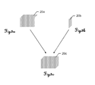
- the surface 23 of the object 20 is detected and a corresponding point cloud 20b (cf. Fig. 3b ), wherein the two surfaces 21,22 are not reachable with the measuring radiation 3 from the perspective of the second device 11.
- the two point clouds 20a-b are thus initially present in two different inner coordinate systems assigned to the respective surveying device 1,11. There is no relative relationship of the two point clouds 20a-b to each other.
- the two point clouds 20a-b are mutually related.
- the referencing of the point clouds 20a-b into a common coordinate system can be achieved by precisely aiming the first surveying device 1 (as a reference point) by the second device 11 as part of a single-point measurement, with a distance between the devices 1,11 and an orientation of the second device 11 is detected.
- the second device 11 is targeted accordingly by the first one (represented by the respectively emitted and receivable measuring radiation 33).
- the relative positioning and alignment of the surveying equipment 1,11 (and thus the inner coordinate systems) is known and the two point clouds 20a-b can be transferred into a common coordinate system (eg in the coordinate system of the first surveying device, which thereby regard as an external coordinate system is) or each other be referenced (means of the invention referencing functionality).
- the point clouds 20a-b can be linked relative to one another and their scan points combined to form an overall point cloud 20c such that the composite point cloud 20c represents the object 20 more than just one of the point clouds 20a-b.
- the two surveying devices 1, 11 may also each have a GNSS receiver 5, 15, by means of which position information of a satellite system can be received in each case (for example GPS signals, GLONASS signals or Galileo signals).
- position information of a satellite system for example GPS signals, GLONASS signals or Galileo signals.
- an absolute position in the earth coordinate system can be determined for each of the surveying systems 1, 1, whereby the identifiable orientation (see above: mutual targeting, but determination of the measuring direction) of the devices 1, 11 also determines the absolute alignment of the devices is determinable (eg north-east orientation).
- the point clouds 20a-c in this outer coordinate system Erdkoordinatensystem
- the positions of the point clouds 20a-c as well as the position (position and orientation) of the object 20 can thus be determined in this system. It can be derived as absolute coordinates - independent of the inner coordinate systems of the surveying equipment 1,11 coordinates - for the object 20.
- a single surveying device at the two set-up 4,14 can be placed one after the other and each time the object 20 is scanned and the point clouds 20a-b are generated.
- an inventive referencing of the respective created point cloud 20a-b then takes place with respect to a superordinate coordinate system, eg by precise individual measurement of the reflector 28 whose position 6 is known in this superordinate coordinate system (in each case known positioning position 4,14). Both point clouds 20a-b can thus be referenced in a common coordinate system.
- unknown positions of the set-up 4.14 can be made a measurement in an external coordinate system that in addition to the positionally known target 28 even more goals (not shown) whose positions are also known in the outer coordinate system, are measured by means of Einzelticianmessfunktionlois - at least with regard to the direction to these destinations.
- point clouds can be generated and referenced to each other or registered in a common coordinate system by scanning a first point cloud in the first set-up position and measuring a reflector in a second position with the single-point measurement functionality exactly. Subsequently, the installation positions of reflector and surveying device are exchanged, scanned another point cloud and the reflector precisely by means of single point measurement appropriate and thereby determines the relative position of the surveying device to the reflector.
- a sequence of referenced measurements can be generated.
- the point clouds generated thereby can thus be provided in a common coordinate system and / or displayed - eg on a display of the surveying device - be.
- an external coordinate system eg in relation to the earth coordinates
- a traverse is then started at a first known reference point and further bridging points are provided by the surveying device and measuring the position of a retroreflector relative to the surveying device. At these artificially provided points, a follow-up measurement can be made. Such a traverse is completed by measuring another known last point. In this case, all reference points artificially provided in the course of the bridging can be updated based on the known position of the last point with respect to their positions. Correspondingly, it is also possible to correct the positions of point clouds created in the context of the traverse.
- measured values of the individual point clouds are used for mutual adaptation. That is, if mutually overlapping measuring ranges were detected by scanning, respective points repeatedly measured can be determined by comparing, in particular averaging, the associated measured values after the respective point clouds have been mutually referenced by means of reference point measurements (single point measurements) and the measuring points are known coordinatively in the same coordinate system are.
- Fig. 4 shows a flowchart for a measuring process with scanning and registering the point cloud generated in the scanning in a coordinate system according to the invention.
- a geodetic surveying apparatus which is designed both for scanning objects and for high-precision measuring of a single point (for example multi-station), is set up in a first setup.
- a measurement of the surveying device corresponding to the measuring requirements is carried out external coordinate system (step 42), where, for example, known point (ie point with a known position in the outer coordinate system) become appropriate.
- known point ie point with a known position in the outer coordinate system
- the measurement range for such a single point measurement is significantly greater than an achievable measurement range for a scan, since the measurement radiation is precisely aligned to the measurement point and held throughout the measurement and thus a longer measurement time - ie a temporally longer integration period - is achievable for a point ,
- a scan area is defined, within which scan points are to be detected with a point-to-point resolution which is likewise to be determined.
- a scan area is defined, within which scan points are to be detected with a point-to-point resolution which is likewise to be determined.
- Scanning 44 of the object is then performed based on the settings set in step 43 by guiding the measurement beam over the object within the defined scan area and (simultaneously) measuring angle and distance values for each scan point.
- a point cloud is generated with the scan points in an internal coordinate system of the surveying device.
- a referencing 45 of the point cloud in the outer coordinate system so that at least the orientation, in particular the position of the point cloud in the outer coordinate system is known or so that a reference between the inner and external coordinate system is determined.
- Object coordinates are thus present in this outer coordinate system, ie a spatial extent and a position and orientation of the object.
- steps 43 and 44 can be carried out according to the invention before step 42.
- the surveying device can optionally be positioned in a further set-up to execute a further scan (step 46), wherein steps 42-45 are again executed in this further set-up or the measuring process is completed 47.
- one or more point clouds are obtained, which are directly in the correct (desired) coordinate system - e.g. in the earth coordinate system, if the positions of the reference points are known therein - without having to perform an additional post-processing step (e.g., at the office workstation) for such registration.
- atmospheric information such as e.g. currently at the respective measurement present air pressure, temperature and / or humidity, and their influence on a respective measurement are taken into account.
- geometric correction data (eg with respect to a north orientation) can be taken into account in the respective measuring processes.
- the referencing of the point cloud according to the invention can be carried out with another coordinate system by means of a controller of the surveying device.
- the controller is intended in particular for the remote control of the device.
Abstract
Geodätisches Vermessungsverfahren mit einem Ableiten einer Oberflächeninformation für ein Objekt (20) und einem geodätisch genauen Einzelpunktmessen zu mindestens einem Referenzpunkt (25-27), wobei durch den mindestens einen Referenzpunkt (25-27) ein Positionsbezug zu einem äusseren Koordinatensystem bereitgestellt wird, eine Messstrahlung (3,33) auf den mindestens einen Referenzpunkt (25-27) ausgerichtet wird und zumindest eine Richtung zu dem Referenzpunkt (25-27) in einem inneren Koordinatensystem bestimmt wird. Ein referenzpunktunabhängiges Scannen zum Ableiten der Oberflächeninformation wird ausgeführt, mit einem Abtasten eines Scanbereichs durch fortlaufendes Ausrichtungsändern der Messstrahlung (3,33), einem Bestimmen von einer jeweiligen Entfernung und einer jeweiligen Ausrichtung der für eine Entfernungsmessung emittierten Messstrahlung (3,33) für innerhalb des bestimmten Scanbereichs liegende Scanpunkte und einem Erzeugen einer die Oberflächeninformation repräsentierenden und die Scanpunkte aufweisenden Punktwolke in dem inneren Koordinatensystem. Zudem erfolgt ein derartiges Referenzieren des inneren Koordinatensystems gegenüber dem äusseren Koordinatensystem basierend zumindest auf dem durch den Referenzpunkt (25-27) bereitgestellten Positionsbezug zu dem äusseren Koordinatensystem und der bestimmten Richtung zu dem Referenzpunkt (25-27) in dem inneren Koordinatensystem, dass zumindest eine Orientierung der Punktwolke im äusseren Koordinatensystem bestimmt ist.Geodetic surveying method with deriving a surface information for an object (20) and a geodetically accurate single point measurement to at least one reference point (25-27), wherein by the at least one reference point (25-27) is provided a position reference to an external coordinate system, a measuring radiation (3,33) is aligned with the at least one reference point (25-27) and at least one direction to the reference point (25-27) is determined in an inner coordinate system. A reference-point-independent scanning for deriving the surface information is carried out with scanning a scanning area by continuously aligning the measuring radiation (3, 33), determining a respective distance and a respective orientation of the measuring radiation (3, 33) emitted for a distance measurement within the certain scan area lying scan points and generating a surface information representing and the scan points having point cloud in the inner coordinate system. In addition, such referencing of the inner coordinate system to the outer coordinate system is based on at least the position reference to the outer coordinate system provided by the reference point (25-27) and the determined direction to the reference point (25-27) in the inner coordinate system that at least one Orientation of the point cloud in the outer coordinate system is determined.
Description
Die Erfindung betrifft ein geodätisches Vermessungsverfahren zum Referenzieren eines Koordinatensystems nach dem Oberbegriff des Anspruchs 1 ein geodätisches Vermessungsgerät nach Anspruch 11 sowie ein Computerprogrammprodukt nach Anspruch 15.The invention relates to a geodetic surveying method for referencing a coordinate system according to the preamble of
Zum Vermessen eines Zielpunktes sind seit der Antike zahlreiche geodätische Vermessungsgeräte bekannt. Als räumliche Standarddaten werden dabei Richtung bzw. Winkel und meist auch Entfernung von einem Messgerät zum zu vermessenden Zielpunkt aufgenommen sowie insbesondere die absolute Position des Messgerätes nebst eventuell vorhandenen Bezugspunkten erfasst.Numerous geodetic surveying instruments have been known since ancient times for measuring a target point. As a spatial standard data thereby direction or angle and usually also distance from a measuring device are recorded to be measured target point and in particular the absolute position of the measuring device together with any existing reference points detected.
Allgemein bekannte Beispiele für solche geodätische Vermessungsgeräte stellen Theodolit, Tachymeter und Totalstation, die auch als elektronischer Tachymeter oder Computer-Tachymeter bezeichnet wird, dar. Eine geodätische Messvorrichtung des Stands der Technik ist beispielsweise in der Veröffentlichungsschrift
In vielen geodätischen Anwendungen erfolgt eine Vermessung von Punkten, indem dort speziell ausgestaltete Zielobjekte platziert werden. Diese bestehen meist aus einem Lotstock mit einem Reflektor (z.B. einem Rundum-Prisma) zur Definition der Messtrecke bzw. des Messpunktes. Bei solchen Vermessungsaufgaben werden zur Steuerung des Messvorgangs sowie zur Festlegung oder Registrierung von Messparametern eine Anzahl von Daten, Anweisungen, Sprache und weiteren Informationen zwischen Zielobjekt - insbesondere einem handhaltbaren Datenerfassungsgerät seitens des Zielobjekts - und zentralem Messgerät übertragen. Beispiele für solche Daten sind die Identifikation des Zielobjekts (Art des verwendeten Prismas), Neigung des Lotstocks, Höhe des Reflektors über Grund, Reflektorkonstanten oder Messwerte wie Temperatur oder Luftdruck. Diese Informationen bzw. situationsbedingten Parameter sind erforderlich, um eine hochpräzise Anzielung und Vermessung des durch den Lotstab mit Prisma definierten Messpunktes zu ermöglichen.Many geodetic applications measure points by placing specially designed targets. These usually consist of a pole with a reflector (eg an all-round prism) for Definition of the measuring section or measuring point. In such surveying tasks, a number of data, instructions, language and other information between the target object - in particular a hand-held data acquisition device on the part of the target object - and central measuring device are transmitted to control the measurement process as well as for the definition or registration of measurement parameters. Examples of such data are the identification of the target object (type of prism used), tilt of the pole, height of the reflector above ground, reflector constants, or measurements such as temperature or air pressure. This information or situation-dependent parameters are required in order to enable a high-precision alignment and measurement of the measuring point defined by the pole with prism.
Moderne Totalstationen weisen in der Regel eine kompakte und integrierte Bauweise auf, wobei meist koaxiale Distanzmesselemente sowie Rechen-, Steuer- und Speichereinheiten in einem Gerät vorhanden sind. Abhängig von der Ausbaustufe der Totalstation können zudem eine Motorisierung der Anziel- bzw. Visiereinrichtung sowie - im Fall der Verwendung von Retroreflektoren (etwa eines Rundum-Prismas) als Ziel-Objekte - Mittel zur automatischen Zielsuche und -verfolgung integriert sein. Als Mensch-Maschine-Schnittstelle kann die Totalstation eine elektronische Anzeige-Steuereinheit - im Allgemeinen eine Mikroprozessor-Recheneinheit mit elektronischen Datenspeichermitteln - mit Display und Eingabemitteln, z.B. einer Tastatur, aufweisen. Der Anzeige-Steuereinheit werden die elektrosensorisch erfassten Messdaten zugeführt, sodass die Position des Zielpunkts durch die Anzeige-Steuereinheit ermittelbar, optisch anzeigbar und speicherbar ist. Aus dem Stand der Technik bekannte Totalstationen können weiters über eine Funkdatenschnittstelle verfügen zum Aufbau einer Funkverbindung zu externen Peripheriekomponenten wie z.B. zu einem handhaltbaren Datenerfassungsgerät, welches insbesondere als Datenlogger oder Feldrechner ausgebildet sein kann.Modern total stations usually have a compact and integrated design, with mostly coaxial distance measuring elements and computing, control and storage units are available in a device. Depending on the expansion stage of the total station, a motorization of the sighting or sighting device and - in the case of the use of retroreflectors (such as a wrap-around prism) as target objects - means for automatic target search and tracking can also be integrated. As a human-machine interface, the total station, an electronic display control unit - in general, a microprocessor processing unit with electronic data storage means - with display and input means, such as a keyboard, have. The display control unit is supplied with the electrosensory measurement data, so that the position of the target point by the display control unit can be determined, visually displayed and stored. From the prior art known total stations can further have a radio data interface for establishing a radio link to external peripheral components such as a hand-held data acquisition device, which may be designed in particular as a data logger or field computer.
Zum Anvisieren bzw. Anzielen des zu vermessenden Zielpunkts weisen gattungsgemässe geodätische Vermessungsgeräte ein Zielfernrohr, wie z.B. ein optisches Teleskop, als Visiereinrichtung auf. Das Zielfernrohr ist im Allgemeinen um eine vertikale Stehachse und um eine horizontale Kippachse relativ zu einer Basis des Messgeräts drehbar, sodass das Fernrohr durch Schwenken und Kippen auf den zu vermessenden Punkt ausgerichtet werden kann.For targeting the target to be measured, generic geodetic surveying instruments include a riflescope, e.g. an optical telescope, as a sighting device. The scope is generally rotatable about a vertical standing axis and about a horizontal tilting axis relative to a base of the measuring device so that the telescope can be aligned by pivoting and tilting on the point to be measured.
Das optische System bzw. der optische Sichtkanal der Visiereinrichtung enthält meist eine Objektivlinsengruppe, ein Bildumkehrsystem, eine Fokussieroptik, eine Strichplatte zur Erzeugung eines Fadenkreuzes und ein Okular, die z.B. in dieser Reihenfolge von der Objektseite her angeordnet sind. Die Position der Fokussierlinsengruppe wird abhängig von der Objektentfernung so eingestellt, dass ein scharfes Objektbild auf der in der Scharfstellebene angeordneten Strichplatte entsteht. Dieses kann dann durch das Okular betrachtet oder z.B. anhand einer koaxial angeordneten Kamera erfasst werden.The optical system or the optical viewing channel of the sighting device usually contains an objective lens group, an image reversing system, a focusing optics, a reticle for creating a crosshair and an eyepiece, which are e.g. arranged in this order from the object side. The position of the focusing lens group is adjusted depending on the object distance so that a sharp object image is formed on the graticule arranged in the focusing plane. This can then be viewed through the eyepiece or e.g. be detected by a coaxially arranged camera.
Beispielhaft ist der Aufbau gattungsgemässer Zielfernrohre von geodätischen Geräten in der
Da Zielobjekte (z.B. die für geodätische Zwecke meist verwendeten Lotstäbe mit Zielmarke wie einem Rundum-Prisma) anhand der Visiereinrichtung trotz der oft bereitgestellten 30-fachen optischen Vergrösserung mit blossem Auge nicht genügend präzise angezielt werden können (d.h. nicht geodätischen Genauigkeitsanforderungen entsprechend), weisen gängige Vermessungsgeräte inzwischen standardmässig eine automatische Zielverfolgungs-Funktion für als Ziel-Reflektor dienende Prismen (ATR: "Automatic Target Recognition") auf. Dafür sind gängigerweise eine weitere separate ATR-Lichtquelle - z.B. ein Multimodefaserausgang, der optische Strahlung mit einer Wellenlänge im Bereich von 850 nm emittiert - und ein spezieller, für diese Wellenlänge sensitiver ATR-Detektor (z.B. CCD-Flächensensor) zusätzlich im Teleskop integriert. Beispielsweise wird in der
Moderne Geräte können additiv zum optischen Sichtkanal eine in das Zielfernrohr integrierte und beispielsweise koaxial oder parallel ausgerichtete Kamera zur Erfassung eines Bildes aufweisen, wobei das erfasste Bild insbesondere als Live-Bild auf dem Display der Anzeige-Steuereinheit und/oder auf einem Display des zur Fernsteuerung verwendeten Peripheriegeräts - wie z.B. des Datenloggers - dargestellt werden kann. Die Optik der Visiereinrichtung kann dabei einen manuellen Fokus - beispielsweise eine Stellschraube zur Veränderung der Position einer Fokussieroptik - aufweisen oder über einen Autofokus verfügen, wobei das Verändern der Fokusposition z.B. durch Servomotoren erfolgt. Beispielsweise ist eine solche Visiereinrichtung eines geodätischen Vermessungsgeräts in der
Mittels einer solchen Bilderfassungseinheit können neben dem Vermessen von bestimmten Zielpunkten auch Bilder einer Messszene erfasst werden. Damit kann ein zu vermessendes Objekt in dem Bild erfasst und gegebenenfalls einem Benutzer auf einem Display des Vermessungsgeräts dargestellt werden. Basierend auf diesem Bild können weitere Informationen für das Objekt abgeleitet werden.By means of such an image acquisition unit, not only the measurement of specific target points but also images of a measurement scene can be detected. Thus, an object to be measured can be detected in the image and possibly displayed to a user on a display of the surveying device. Based on this image, further information for the object can be derived.
Durch eine entsprechende Bildverarbeitung können beispielsweise eine Oberflächenbeschaffenheit für das Objekt oder eine räumliche Ausdehnung des Objekts zumindest grob bestimmt werden. Die räumliche Ausdehnung oder die Form des Objekts können dabei mittels Kantenextraktion auf Basis des Bildes bestimmt werden.By appropriate image processing, for example, a surface texture for the object or a spatial extent of the object can be determined at least roughly. The spatial extent or the shape of the object can be determined by edge extraction based on the image.
Für eine genauere Bestimmung dieser Objekteigenschaften können zusätzlich zu den Bildinformationen Positionsinformationen für einen oder mehrere Punkte, die auf dem Objekt liegen, berücksichtigt werden. Hierzu wird der eine oder die mehreren Punkte mit dem Vermessungsgerät genau angezielt und vermessen. Die so hinsichtlich ihrer Position bestimmten Punkte werden als so genannte Stützpunkte zusammen mit der Bildinformation verarbeitet, wodurch eine genauere Angabe z.B. über die Lage des im Bild erfassten Objektteils gemacht werden kann.For a more accurate determination of these object properties, position information for one or more points lying on the object may be taken into account in addition to the image information. For this purpose, the one or more points is precisely targeted and measured with the surveying device. The points thus determined with respect to their position are processed as so-called fulcrums together with the image information, whereby a more accurate indication is given e.g. can be made on the location of the captured in the image object part.
Nachteilig ist hierbei, dass eine grossflächige topographische und geodätisch genaue Objektvermessung mit einer Totalstation nicht möglich ist bzw. einen unverhältnismässig hohen Zeitaufwand bedeutet (im Vergleich zu einem Bilderfassen des Objekts), da jeder zu vermessende Punkt einzeln angezielt und dessen Position bei fester Ausrichtung der Messstrahlung bestimmt werden müsste.The disadvantage here is that a large-scale topographic and geodetically accurate object measurement with a total station is not possible or a disproportionately high amount of time means (compared to a picture capture of the object), as each to be measured Point individually targeted and whose position would have to be determined with fixed orientation of the measuring radiation.
Zudem kann insbesondere die Lagebestimmung für den durch das Bild abgebildeten Objektteil nur abhängig von den bestimmten Stützpunkten vorgenommen werden und eine gute Genauigkeit nur mit einer entsprechend grossen Anzahl von Stützpunkten erreicht werden, wobei weiterhin nur auf Basis von einer Bildverarbeitung die Form des Objektteils (z.B. wenn das Objekt eine gekrümmte Oberfläche aufweist) ebenfalls nur mit einer sehr limitierten Genauigkeit ermittelt werden kann.In addition, in particular, the position determination for the object part imaged by the image can only be made dependent on the specific interpolation points and a good accuracy can only be achieved with a correspondingly large number of interpolation points, with the shape of the object part (eg if based on image processing) remaining unchanged the object has a curved surface) can also be determined only with a very limited accuracy.
Es ist daher eine Aufgabe der vorliegenden Erfindung ein verbessertes Vermessungsgerät und ein entsprechendes Verfahren bereitzustellen, welches eine verbesserte, schnellere und genauere grossflächige Oberflächenvermessung eines Objekts erlaubt, insbesondere wobei die Lage des zu vermessenden Objekts (georeferenziert) bestimmbar ist.It is therefore an object of the present invention to provide an improved surveying device and a corresponding method, which allows an improved, faster and more accurate large-area surface measurement of an object, in particular wherein the position of the object to be measured (georeferenced) can be determined.
Eine weitere Aufgabe der Erfindung ist das Bereitstellen eines entsprechenden Vermessungsgeräts, insbesondere einer Totalstation, wobei eine genauere Objekterfassung und zudem eine Bereitstellung von geräteunabhängigen Objektkoordinaten für das Objekt ausführbar ist.Another object of the invention is to provide a corresponding surveying device, in particular a total station, wherein a more accurate object detection and also a provision of device-independent object coordinates for the object is executable.
Eine weitere Aufgabe der Erfindung ist das Bereitstellen eines Vermessungsgeräts, mit dem ein Messfortschritt bezüglich eines absoluten Koordinatensystems (alternativ zu dem inneren Bezugssystem des Messgeräts) überwachbar ist.A further object of the invention is the provision of a surveying device, with which a measurement progress with respect to an absolute coordinate system (as an alternative to the inner reference system of the measuring device) can be monitored.
Diese Aufgaben werden durch die Verwirklichung der kennzeichnenden Merkmale der unabhängigen Ansprüche gelöst. Merkmale, die die Erfindung in alternativer oder vorteilhafter Weise weiterbilden, sind den abhängigen Patentansprüchen zu entnehmen.These objects are achieved by the realization of the characterizing features of the independent claims. Features that the invention in alternative or weiterzubilden advantageously, are given in the dependent claims.
Die Erfindung betrifft ein geodätisches Vermessungsverfahren zum Referenzieren eines Koordinatensystems mittels eines geodätischen Vermessungsgeräts. Dabei erfolgen ein Ableiten einer Oberflächeninformation für ein Objekt bezüglich einem inneren Koordinatensystem des geodätischen Vermessungsgeräts, insbesondere bezüglich einer Form und/oder räumlichen Ausdehnung des Objekts, und ein geodätisch genaues Einzelpunktmessen zu mindestens einem Referenzpunkt, wobei durch den mindestens einen Referenzpunkt ein Positionsbezug zu einem äusseren Koordinatensystem bereitgestellt wird, eine Messstrahlung präzise auf den mindestens einen Referenzpunkt ausgerichtet wird und bei der Ausrichtung der Messstrahlung auf den mindestens einen Referenzpunkt zumindest eine Richtung zu dem Referenzpunkt in dem inneren Koordinatensystem bestimmt wird.The invention relates to a geodetic surveying method for referencing a coordinate system by means of a geodetic surveying device. In this case, derive a surface information for an object with respect to an inner coordinate system of the geodetic surveying device, in particular with respect to a shape and / or spatial extent of the object, and a geodetically accurate Einzelpunktmessen to at least one reference point, wherein by the at least one reference point, a position reference to an external Coordinate system is provided, a measuring radiation is precisely aligned with the at least one reference point and at least one direction to the reference point in the inner coordinate system is determined when aligning the measuring radiation to the at least one reference point.
Erfindungsgemäss wird zusätzlich ein referenzpunktunabhängiges Scannen zum Ableiten der Oberflächeninformation ausgeführt, mit einem Abtasten eines bezüglich dem Objekt bestimmten Scanbereichs durch fortlaufendes Ausrichtungsändern der Messstrahlung, mit einem Bestimmen von einer jeweiligen Entfernung und einer jeweiligen Ausrichtung der für eine Entfernungsmessung emittierten Messstrahlung für innerhalb des bestimmten Scanbereichs liegende Scanpunkte, insbesondere in einer vorbestimmten Scanpunktauflösung, und mit einem Erzeugen einer die Oberflächeninformation repräsentierenden und die Scanpunkte aufweisenden Punktwolke in dem inneren Koordinatensystem. Zudem wird ein derartiges Referenzieren, insbesondere automatisches Referenzieren, des inneren Koordinatensystems gegenüber dem äusseren Koordinatensystem basierend zumindest auf dem durch den Referenzpunkt bereitgestellten Positionsbezug zu dem äusseren Koordinatensystem und der bestimmten Richtung zu dem Referenzpunkt in dem inneren Koordinatensystem ausgeführt, dass zumindest eine Orientierung, insbesondere eine Lage, der Punktwolke im äusseren Koordinatensystem bestimmt ist.In addition, according to the present invention, non-point scanning is performed for deriving the surface information by scanning a scan area with respect to the object by continuously aligning the measurement radiation, determining a respective distance and a respective orientation of the measurement radiation emitted for a distance measurement for within the determined scan area Scan points, in particular at a predetermined scan point resolution, and with generating a point cloud representing the surface information and having the scan points in the inner coordinate system. In addition, such referencing, in particular automatic homing of the inner coordinate system relative to the outer coordinate system based at least on the position reference to the outer coordinate system provided by the reference point and the specific direction to the reference point in the inner coordinate system that at least one orientation, in particular a position, the point cloud in the outer Coordinate system is determined.
Erfindungsgemäss kann somit sowohl eine Objektfläche mit einer vorbestimmten Punkt-zu-Punkt-Auflösung scannend erfasst werden (z.B. mit einer Messrate von 1000 bis 10000 oder mehr Messpunkten pro Sekunde und mit einer geodätischen Massstäben entsprechenden Messreichweite von bis zu Kilometern) als auch ein einzelner Referenzpunkt hochgenau angezielt und vermessen werden. Durch das Scannen wird eine Punktwolke für das zu vermessende Objekt abgeleitet, wobei die Position, Orientierung und Skalierung der Wolke zunächst nur in dem inneren Koordinatensystem des Vermessungsgeräts bekannt und bestimmt sind und dadurch (nur) relative Aussagen über das Objekt in Bezug auf das innere Bezugssystem möglich sind.According to the invention, both an object surface with a predetermined point-to-point resolution can thus be detected by scanning (eg with a measuring rate of 1000 to 10,000 or more measuring points per second and with a measuring range of up to kilometers corresponding to geodetic scales) as well as a single reference point highly accurately targeted and measured. By scanning a point cloud is derived for the object to be measured, the position, orientation and scaling of the cloud are first known and determined only in the inner coordinate system of the surveying device and thereby (only) relative statements about the object with respect to the inner reference system possible are.
Zur Bestimmung z.B. einer absoluten Position, Orientierung und/oder räumlichen Ausdehnung der Punktwolke muss die Punktwolke in einem übergeordneten (äusseren) Koordinatensystem registriert werden, d.h. das innere Koordinatensystem wird gegenüber dem übergeordneten Koordinatensystem referenziert. Dieses Registrieren erfolgt erfindungsgemäss durch das Vermessen des einzelnen Referenzpunkts (oder mehrerer), dessen Position z.B. in dem übergeordneten Koordinatensystem bekannt ist (durch den Punkt wird also ein Positionsbezug zu dem äusseren Koordinatensystem bereitgestellt). Durch diese Informationen (bekannte Position im übergeordneten Koordinatensystem und durch die durch das Vermessen zumindest bekannte Richtung zu dem Punkt im inneren Koordinatensystem) erfolgt nun das gegenseitige Referenzieren der Koordinatensysteme, d.h. die Punktwolke wird in dem übergeordneten Koordinatensystem registriert.To determine, for example, an absolute position, orientation and / or spatial extent of the point cloud, the point cloud must be registered in a higher (outer) coordinate system, ie the inner coordinate system is referenced relative to the higher-level coordinate system. This registration is carried out according to the invention by measuring the individual reference point (or several) whose position is known, for example, in the superordinate coordinate system (ie a position reference to the external coordinate system is provided by the point). Through this Information (known position in the parent coordinate system and by the at least known direction to the point in the inner coordinate system by the surveying) is now the mutual referencing of the coordinate systems, ie the point cloud is registered in the parent coordinate system.
Damit sind die Position, die Orientierung und auch die Skalierung der Punktwolke und ferner auch die Orientierung und/oder Lage des Objekts und dessen räumliche Ausdehnung in diesem äusseren System bestimmt und bekannt.Thus, the position, the orientation and also the scaling of the point cloud and also the orientation and / or position of the object and its spatial extent in this outer system are determined and known.
Die Schritte des Scannens, Referenzpunktvermessens und des gegenseitigen Registrierens werden dabei erfindungsgemäss alle mit und durch das Vermessungsgerät (oder einen dem Vermessungsgerät zugeordneten Controller) ausgeführt. Somit ist kein zusätzlicher post-processing-Schritt für das Registrieren der Punktwolke mehr erforderlich.According to the invention, the steps of scanning, reference point measurement and mutual registration are all carried out with and by the surveying device (or a controller assigned to the surveying device). Thus, no additional post-processing step is required for registering the point cloud.
Für das Bereitstellen des Positionsbezugs zu dem äusseren Koordinatensystem ist erfindungsgemäss insbesondere eine absolute Position des mindestens einen Referenzpunkts in dem äusseren Koordinatensystem bekannt und das Referenzieren erfolgt basierend auf der bekannten absoluten Position des mindestens einen Referenzpunkts.For providing the position reference to the outer coordinate system, according to the invention, in particular, an absolute position of the at least one reference point in the outer coordinate system is known, and the referencing is based on the known absolute position of the at least one reference point.
Der mindestens eine Referenzpunkt kann im Rahmen der Erfindung insbesondere in dem äusseren Koordinatensystem bereitgestellt werden durch einen geodätisch referenzieren Einmesspunkt oder einen Retro-Reflektor oder ein in einer bekannten Positionierung oder Ausrichtung aufgestelltes geodätisches Vermessungsgerät.In the context of the invention, the at least one reference point can be provided in particular in the outer coordinate system by means of a geodetically referenced calibration point or a retro-reflector or a geodetic surveying device set up in a known positioning or orientation.
Gemäss einer speziellen Ausführungsform der Erfindung werden eine Entfernung zu dem mindestens einen Referenzpunkt und eine Position des Referenzpunkts in dem inneren Koordinatensystem bestimmt und das Referenzieren erfolgt zumindest basierend auf der bestimmten Position des Referenzpunkts im inneren Koordinatensystem.According to a specific embodiment of the invention, a distance to the at least one Reference point and a position of the reference point in the inner coordinate system determines and the referencing takes place at least based on the specific position of the reference point in the inner coordinate system.
Hinsichtlich der Ausführung des Scannvorgangs wird im Rahmen des Scannens erfindungsgemäss im Speziellen bei dem Bestimmen der jeweiligen Entfernung und der jeweiligen Ausrichtung der Messstrahlung die Ausrichtung der Messstrahlung innerhalb des bestimmten Scanbereichs kontinuierlich verändert. Dadurch kann ein echtes scannendes Abtasten von Objektoberfläche erreicht werden, wobei Messungen mit einem erfindungsgemässen geodätischen Vermessungsgerät, insbesondere mit einer Totalstation oder einem Theodoliten, während der Bewegung des Messstrahls hinreichend präzise ausgeführt werden können.With regard to the execution of the scanning operation, in the context of the scanning according to the invention, in particular when determining the respective distance and the respective orientation of the measuring radiation, the orientation of the measuring radiation within the specific scanning area is continuously changed. As a result, a true scanning scanning of the object surface can be achieved, wherein measurements with a geodetic surveying device according to the invention, in particular with a total station or a theodolite, can be carried out sufficiently precisely during the movement of the measuring beam.
Ein derartiges Scannen mit einem geodätischen Vermessungsgerät ist im Wesentlichen durch die Verwendung hochgenauer, schneller und präzise steuerbarere Stellmotoren bzw. Servomotoren erzielbar, wodurch die Anzieleinheit des Vermessungsgeräts und damit die Messstrahlung schnell, exakt und kontinuierlich geführt werden kann und gleichzeitig die Winkelstellungen der Anzieleinheit und Entfernungen zu Zielen gemessen werden können. Die Steuerung- und Auswerteeinheit des Geräts ist zudem derart konfiguriert, dass die erfassten Messdaten entsprechend schnell verarbeitet werden können.Such a scanning with a geodetic surveying device is essentially achievable by the use of highly accurate, faster and more precisely controllable servomotors or servomotors, whereby the target unit of the surveying device and thus the measuring radiation can be guided quickly, accurately and continuously and at the same time the angular positions of the target unit and distances can be measured to goals. The control and evaluation unit of the device is also configured so that the acquired measurement data can be processed accordingly fast.
Im Rahmen des Referenzierens kann das innere Koordinatensystem erfindungsgemäss derart angepasst werden, insbesondere hinsichtlich Lage und Skalierung des inneren Koordinatensystems, dass das innere Koordinatensystem mit dem äusseren Koordinatensystem zusammen fällt, insbesondere dem äusseren Koordinatensystem entspricht. Das innere Koordinatensystem kann hierfür entsprechend rotiert, versetzt und/oder dessen Skalierung verändert werden. Das innere Koordinatensystem ist dann insbesondere identisch zum äusseren Koordinatensystem.In the context of referencing, the inner coordinate system according to the invention can be adapted in such a way, in particular with regard to position and scaling of the inner coordinate system, that the inner coordinate system coincides with the outer coordinate system, in particular corresponds to the outer coordinate system. The inner coordinate system can be correspondingly rotated, offset and / or its scaling changed. The inner coordinate system is then in particular identical to the outer coordinate system.
Gemäss einer weiteren speziellen Ausführungsform der Erfindung erfolgt das Referenzieren des inneren Koordinatensystems gegenüber dem äusseren Koordinatensystem basierend auf weiteren Referenzinformationen, insbesondere basierend auf einer zusätzlichen GNSS-Positionsinformation und/oder auf einem zusätzlichen dem inneren und äusseren Koordinatensystem gemeinsamen bekannten Punkt, dessen Position beispielsweise durch Einzelpunktmessen bestimmt wird.According to a further specific embodiment of the invention, the referencing of the inner coordinate system with respect to the outer coordinate system is based on further reference information, in particular based on an additional GNSS position information and / or on an additional known to the inner and outer coordinate system known point whose position, for example, by single-point measurement is determined.
Bezüglich einer Berücksichtigung von aktuell vorliegenden Messbedingungen kann im Rahmen des Vermessungsverfahrens erfindungsgemäss eine atmosphärische Zustandsinformation erfasst werden und/oder eine geometrische Messinformation definiert sein, insbesondere in Form von meteorologischen Daten oder Messachsenfehler, insbesondere Umgebungstemperatur, Luftdruck und/oder Luftfeuchtigkeit.With regard to consideration of currently existing measurement conditions, according to the invention an atmospheric state information can be detected and / or a geometric measurement information can be defined, in particular in the form of meteorological data or measurement axis errors, in particular ambient temperature, air pressure and / or air humidity.
Insbesondere wird in diesem Zusammenhang bei dem Bestimmen der Entfernung für die jeweiligen Scanpunkte und/oder bei dem Bestimmen der Entfernung zu dem mindestens einen Referenzpunkt die atmosphärische Zustandsinformation und/oder geometrische Messinformation verarbeitet und basierend darauf erfolgt eine Entfernungskorrektur für das Bestimmen der jeweiligen Entfernung. Alternativ oder zusätzlich können die im Rahmen des Scannens bestimmten Scanpunkte bezüglich deren Position in dem äusseren Koordinatensystem, insbesondere die Orientierung der Punktwolke in dem inneren Koordinatensystem, basierend auf den atmosphärischen Zustandsinformationen und/oder geometrische Messinformation angepasst werden.In particular, in this context, in determining the distance for the respective scan points and / or in determining the distance to the at least one reference point, the atmospheric state information and / or geometric measurement information is processed and based thereon, a range correction is performed for determining the respective distance. Alternatively or additionally, the scan points determined in the context of the scanning can be related to their position in the outer coordinate system, in particular the orientation of the Point cloud in the inner coordinate system, based on the atmospheric state information and / or geometric measurement information to be adjusted.
Mit anderen Worten kann bei einem Messvorgang (Einzelpunktmessen oder Scannen) eine derartige Zustandsinformation miterfasst werden und basierend auf dieser Information eine Messkorrektur vorgenommen werden. Die Korrektur kann dabei z.B. mittels einer "Look-Up Table", durch die z.B. für eine bestimmte Umgebungstemperatur ein zugehöriger Korrekturwert definiert ist, ermittelt werden.In other words, such a state information can be detected in a measurement process (single-point measurement or scanning) and a measurement correction can be made based on this information. The correction may be e.g. by means of a look-up table, through which e.g. for a given ambient temperature, an associated correction value is defined to be determined.
Gemäss einer weiteren speziellen Ausführungsform der Erfindung werden mindestens ein weiteres Scannen von weiteren Scanpunkten ausgeführt, eine die weiteren Scanpunkte aufweisende weitere Punktwolke in einem weiteren Koordinatensystem abgeleitet, ein geodätisch genaues Einzelpunktmessen zu dem mindestens einem Referenzpunkt und/oder zu einem weiteren Referenzpunkt mit Bestimmen wenigstens der Richtung zu dem Referenzpunkt und/oder zu dem weiteren Referenzpunkt in dem weiteren Koordinatensystem ausgeführt und das weitere Koordinatensystem gegenüber dem äusseren Koordinatensystem basierend zumindest auf der bestimmten Richtung zu dem Referenzpunkt in dem weiteren Koordinatensystem referenziert. Diese beiden Schritte des weiteren Scannens und des Einzelpunktmessens erfolgen insbesondere in identischer Aufstellung des Vermessungsgeräts, so dass einem Scanvorgang ein bestimmter Einzelpunktmessvorgang zugeordnet werden kann.According to a further specific embodiment of the invention, at least one further scanning of further scan points is carried out, a further point cloud having the further scan points derived in a further coordinate system, a geodetically accurate single point measurement to the at least one reference point and / or to a further reference point with determining at least the Executed direction to the reference point and / or to the further reference point in the further coordinate system and referenced the further coordinate system relative to the outer coordinate system based at least on the specific direction to the reference point in the further coordinate system. These two steps of the further scanning and the individual point measurement are carried out in particular in an identical arrangement of the surveying device, so that a specific single-point measuring process can be assigned to a scanning process.
Das Scannen und das mindestens eine weitere Scannen erfolgen dabei insbesondere aus unterschiedlichen Perspektiven von unterschiedlichen Aufstellpunkten aus, wobei die Orientierungen (oder Lagen) der jeweiligen Punktwolken in dem äusseren Koordinatensystem und dadurch die Orientierungen der jeweiligen Punktwolken relativ zueinander bestimmt sind.The scanning and the at least one further scanning take place in particular from different Perspectives from different set-up points, wherein the orientations (or positions) of the respective point clouds in the outer coordinate system and thereby the orientations of the respective point clouds are determined relative to each other.
Mit dieser erfindungsgemässen Verfahrensvariante können beispielsweise mehrere Punktwolken von einem oder mehreren Objekten aus unterschiedlichen Perspektiven erfasst werden und diese Punktwolken gegenseitig so referenziert werden bzw. in einem äusseren Koordinatensystem registriert werden, dass diese in einem gemeinsamen Koordinatensystem vorliegen. Beispielsweise werden alle Punktwolken in einem gemeinsamen übergeordneten System referenziert, so dass für jede Punktwolke die relative Lage und Skalierung in diesem System definiert ist.With this method variant according to the invention, for example, a plurality of point clouds can be detected by one or more objects from different perspectives and these point clouds can be referenced to one another or registered in an external coordinate system such that they are present in a common coordinate system. For example, all point clouds are referenced in a common parent system so that for each point cloud the relative location and scale is defined in that system.
Dadurch können z.B. die räumliche Ausdehnung und/oder die Form eines aus mehreren Perspektiven erfassten Objekts genau rekonstruiert werden und ein wirklichkeitsgetreues Modell für das Objekt basierend auf den erzeugten Punktwolken erstellt werden.Thereby, e.g. the spatial extent and / or the shape of an object captured from multiple perspectives are accurately reconstructed and a realistic model for the object based on the generated point clouds are created.
Das von unterschiedlichen Aufstellpunkten ausgehende Scannen (und das damit verbundene jeweilige Referenzieren der dadurch erzeugten Punktwolke) kann mit einem Vermessungsgerät und wechselndem Aufstellen des Geräts an diesen Aufstellpunkten erfolgen. Alternativ können hierfür mehrere geodätische Vermessungsgeräte an den unterschiedlichen Aufstellpunkten eingesetzt werden.The emanating from different set-up scanning (and the associated respective referencing of the point cloud generated thereby) can be done with a surveying device and changing set up of the device at these points. Alternatively, several geodetic surveying equipment can be used at the different set-up points.
Bezüglich einer Genauigkeitssteigerung der für die Scanpunkte bestimmten Positionen erfolgt gemäss einer speziellen Ausführung der Erfindung basierend auf dem Referenzieren des inneren Koordinatensystems und des weiteren Koordinatensystems gegenüber dem äusseren Koordinatensystem ein zumindest teilweises, gegenseitiges Anpassen von Positionen der bestimmten Scanpunkte und/oder der weiteren Scanpunkte im äusseren Koordinatensystem, insbesondere erfolgt eine Positionskorrektur.With regard to an increase in accuracy of the positions determined for the scan points, according to a specific embodiment of the invention based on the Referencing the inner coordinate system and the further coordinate system relative to the outer coordinate system at least partially, mutual adjustment of positions of the specific scan points and / or the other scan points in the outer coordinate system, in particular, a position correction is performed.
Erfindungsgemäss wird das geodätische Vermessungsverfahren durch und mit dem geodätischen Vermessungsgerät ausgeführt, wobei das Vermessungsgerät zumindest eine Scanfunktionalität zum scannenden Erfassen der Scanpunkte und Erzeugen der Punktwolke und eine Einzelpunktmessfunktionalität zum hochpräzisen Richtungsbestimmen zu dem Referenzpunkt aufweist. Insbesondere ist das Vermessungsgerät zur Ausführung des Vermessungsverfahrens gemäss einer der im Folgenden angeführten Ausführungsformen ausgebildet. Die Verfahrensschritte Scannen, Einzelpunktmessen und Referenzieren werden erfindungsgemäss alle mit dem Vermessungsgerät (insbesondere bezüglich dem Scannen und Einzelpunktmessen) und direkt auf dem Vermessungsgerät (insbesondere bezüglich dem Referenzieren) durchgeführt.According to the invention, the geodetic surveying method is carried out by and with the geodetic surveying device, wherein the surveying device has at least one scanning functionality for scanning detection of the scan points and generating the point cloud and single point measuring functionality for high-precision direction determination to the reference point. In particular, the surveying device for carrying out the surveying method is designed in accordance with one of the embodiments mentioned below. The method steps of scanning, single-point measurement and homing are all performed according to the invention with the surveying device (in particular with respect to the scanning and single-point measurements) and directly on the surveying device (in particular with respect to the referencing).
Die Erfindung betrifft auch ein geodätisches Vermessungsgerät, insbesondere Totalstation oder Multistation, mit einer eine Schwenkachse definierenden Basis, einem auf der Basis angeordneten, um die Schwenkachse relativ zur Basis schwenkbaren Aufbau, wobei der Aufbau eine im wesentlichen orthogonal zur Schwenkachse stehende Kippachse definiert, und mit einer Anzieleinheit, insbesondere Ziel-Fernrohr, wobei die Anzieleinheit um die Kippachse relativ zum Aufbau schwenkbar angeordnet ist und eine Emissionseinheit mit einer Strahlquelle zur Erzeugung und Emission einer Messstrahlung aufweist. Zudem verfügt das Vermessungsgerät über eine Entfernungsmessfunktionalität zur Messung von Entfernungen zu Punkten, über eine Winkelmessfunktionalität zur Messung einer Ausrichtung der Messstrahlung und über eine Steuerungs- und Verarbeitungseinheit zur Datenverarbeitung und zur Steuerung des Vermessungsgeräts.The invention also relates to a geodetic surveying device, in particular total station or multi station, with a pivot axis defining base, arranged on the base, about the pivot axis relative to the base pivotable structure, wherein the structure defines a substantially orthogonal to the pivot axis tilt axis, and with a target unit, in particular target telescope, wherein the target unit is arranged pivotable about the tilt axis relative to the structure and has an emission unit with a beam source for generating and emitting a measurement radiation. Also features the surveying device via a distance measuring functionality for the measurement of distances to points, via an angle measuring functionality for measuring an alignment of the measuring radiation and a control and processing unit for data processing and for controlling the surveying device.
Des Weiteren verfügt das Gerät über eine Einzelpunktmessfunktionalität, wobei die Einzelpunktmessfunktionalität durch die Steuerungs- und Verarbeitungseinheit derart ausführbar ist, dass durch ein hochpräzises Ausrichten der Messstrahlung auf mindestens einen Referenzpunkt dieser geodätisch genau vermessbar ist, wobei durch den mindestens einen Referenzpunkt ein Positionsbezug zu einem äusseren Koordinatensystem bereitstellt wird, und dass bei der Ausrichtung der Messstrahlung auf den mindestens einen Referenzpunkt zumindest eine Richtung zu dem Referenzpunkt in dem inneren Koordinatensystem des Vermessungsgeräts bestimmbar ist.Furthermore, the device has a single-point measuring functionality, wherein the single-point measuring functionality by the control and processing unit can be executed such that by a high-precision alignment of the measuring radiation to at least one reference point this geodetically accurate vermessbar, wherein by the at least one reference point a position reference to an external Coordinate system is provided, and that at least one direction to the reference point in the inner coordinate system of the surveying device can be determined in the orientation of the measuring radiation on the at least one reference point.
Mit anderen Worten wird bei Ausführung der Einzelpunktmessfunktionalität automatisch gesteuert durch die Steuerungs- und Verarbeitungseinheit die Messstrahlung hochpräzise auf mindestens einen (scanpunktunabhängigen) Referenzpunkt ausgerichtet, wobei durch den mindestens einen Referenzpunkt ein Positionsbezug zu einem äusseren Koordinatensystem bereitstellt wird, insbesondere wobei eine absolute Position des Referenzpunkts in einem äusseren Koordinatensystem bekannt ist, der Referenzpunkt geodätisch genau vermessen wird und zumindest eine Richtung zu dem Referenzpunkt in dem inneren Koordinatensystem bestimmt wird.In other words, when performing the Einzelpunktmessfunktionalität automatically controlled by the control and processing unit, the measuring radiation to at least one (scanpunktunabhängigen) reference point aligned, being provided by the at least one reference point a position reference to an outer coordinate system, in particular where an absolute position of the reference point is known in an outer coordinate system, the reference point is measured geodetically accurate and at least one direction is determined to the reference point in the inner coordinate system.
Erfindungsgemäss ist das Vermessungsgerät ferner mit einer referenzpunktunabhängige Scanfunktionalität ausgerüstet, wobei die Scanfunktionalität durch die Steuerungs- und Verarbeitungseinheit derart ausführbar ist, dass durch ein fortlaufendes Ausrichtungsändern der Messstrahlung auf innerhalb eines bestimmten Scanbereichs liegende Scanpunkte die Scanpunkte mit einer vorbestimmten Scanpunktauflösung vermessbar sind und eine die Scanpunkte aufweisende Punktwolke in einem inneren Koordinatensystem des Vermessungsgeräts erzeugbar ist. Ein Ändern der Ausrichtung der Messstrahlung erfolgt dabei fortlaufend, insbesondere kontinuierlich, so dass die Scannpunkte innerhalb des Scanbereichs dadurch sukzessive abtastbar sind.According to the invention, the surveying device is further equipped with a reference point-independent scanning functionality, wherein the scanning functionality can be executed by the control and processing unit such that the scan points can be measured with a predetermined scan point resolution and one the scan points by continuously aligning the measurement radiation to scan points lying within a certain scan area exhibiting point cloud in an inner coordinate system of the surveying device can be generated. A change in the orientation of the measuring radiation is carried out continuously, in particular continuously, so that the scanning points within the scan area are thereby successively scanned.
Mit anderen Worten erfolgt bei Ausführung der Scanfunktionalität automatisch gesteuert durch die Steuerungs- und Verarbeitungseinheit ein Scannen mit einem fortlaufenden Ändern der Ausrichten der Messstrahlung auf innerhalb eines bestimmten Scanbereichs liegende Scanpunkte und einem Vermessen der Scanpunkte mit einer vorbestimmten Scanpunktauflösung und einem Erzeugen einer die Scanpunkte aufweisenden Punktwolke in einem inneren Koordinatensystem des Vermessungsgeräts.In other words, when the scan functionality is executed by the control and processing unit, scanning is performed with a continuous change of the alignment of the measurement radiation to scan points lying within a specific scan area and measurement of the scan points with a predetermined scan point resolution and generation of a point cloud having the scan points in an internal coordinate system of the surveying device.
Das Vermessungsgerät weist zusätzlich eine Referenzierungsfunktionalität auf, bei deren Ausführung durch die Steuerungs- und Verarbeitungseinheit ein Referenzieren des inneren Koordinatensystems gegenüber dem äusseren Koordinatensystem basierend zumindest auf dem durch den Referenzpunkt bereitgestellten Positionsbezug zu dem äusseren Koordinatensystem und der durch die Einzelpunktmessfunktionalität bestimmbaren Richtung zu dem Referenzpunkt in dem inneren Koordinatensystem so erfolgt, dass zumindest eine Orientierung der Punktwolke im äusseren Koordinatensystem bestimmt ist.The surveying device additionally has a referencing functionality, when executed by the control and processing unit, referencing the inner coordinate system relative to the outer coordinate system based at least on the position reference to the outer coordinate system provided by the reference point and the direction determinable by the Einzelpunktmessfunktionalität to the reference point in so does the inner coordinate system that at least one orientation of the point cloud is determined in the outer coordinate system.
Gemäss einer speziellen, erfindungsgemässen Ausführungsform des Vermessungsgeräts ist die Steuerungs- und Verarbeitungseinheit derart konfiguriert, dass mit dem geodätischen Vermessungsgerät ein oben beschriebenes geodätisches Vermessungsverfahren ausführbar ist.According to a specific embodiment of the surveying device according to the invention, the control and processing unit is configured such that a geodetic surveying method described above can be carried out with the geodetic surveying device.
Für eine verbesserte Benutzerfreundlichkeit kann das Vermessungsgerät insbesondere eine Fernsteuereinheit mit einer Auswerteeinheit aufweisen, wobei die Referenzierungsfunktionalität durch die Auswerteeinheit ausführbar ist und/oder eine Anzeigeeinheit zur Darstellung von Messinformation aufweisen, insbesondere wobei ein Scanfortschritt durch ein zumindest teilweises Darstellen von Scanpunkten einer Punktwolke darstellbar ist.For improved user friendliness, the surveying device can in particular have a remote control unit with an evaluation unit, wherein the referencing functionality can be executed by the evaluation unit and / or have a display unit for displaying measurement information, in particular wherein a scan progress can be represented by an at least partial representation of scan points of a point cloud.
Zur Erfassung weiterer positionsrelevanter Informationen verfügt das erfindungsgemässe Vermessungsgerät in einer speziellen Ausbaustufe über ein GNSS-Modul zur Erfassung von GNSS-Positionsinformation, insbesondere wobei die GNSS-Positionsinformation zur Positionskorrektur der Scanpunkte und/oder der Punktwolke im äusseren Koordinatensystem und/oder zur Messwertanpassung bei der Scanpunktvermessung und/oder Referenzpunktvermessung verarbeitbar ist.To acquire further position-relevant information, the surveying device according to the invention has in a special expansion stage a GNSS module for acquiring GNSS position information, in particular the GNSS position information for position correction of the scan points and / or the point cloud in the outer coordinate system and / or for measurement value adaptation in the case of Scan point measurement and / or reference point measurement is processable.
Eine solche GNSS-Information kann beispielsweise verwendet werden um ein so genantes "Smart-Station Setup" auszuführen, d.h. dass beispielsweise die Richtung zu einem Anschlusspunkt mit einem Vermessungsgerät ("Smart-Station") gemessen wird, jedoch die Koordinaten dieses angemessenen Punkts (noch) nicht bekannt sind. Die Position des Punkts wird erst bekannt durch ein nachfolgendes Positionieren des Vermessungsgeräts auf dem Anschlusspunkt, wobei mittels GNSS eine Positionsbestimmung an diesem Punkt erfolgt. Sobald dieser Punkt dadurch bekannt ist, wird die Orientierung des ersten Setups (also bei Anzielung des Anschlusspunkts) durch Berücksichtigen der ermittelten Punktposition berechnet und aktualisiert. Dabei kann entsprechend auch eine in der ersten Aufstellung erzeugte Punktwolke aktualisiert werden.Such GNSS information can be used, for example, to perform a so-called "smart station setup", ie that the direction to a connection point is measured with a surveying device ("smart station"), however, the coordinates of this appropriate point (still ) are not known. The position of the point is first known by a subsequent positioning of the Surveying equipment on the connection point, whereby by means of GNSS a position determination takes place at this point. As soon as this point is known, the orientation of the first setup (ie, when the connection point is approached) is calculated and updated by taking into account the determined point position. In this case, a point cloud generated in the first setup can also be updated accordingly.
Das Vermessungsgerät kann insbesondere derart ausgebildet sein, dass die Anzieleinheit über ein Abbildungssystem mit einer eine Fokussiergruppe aufweisenden Abbildungsoptik und einer Bildebene zur Erzeugung und graphischen Bereitstellung einer Abbildung eines Anzielsichtfeldes verfügt, insbesondere wobei das Anzielsichtfeld durch das Abbildungssystem definiert ist und die Abbildung des Anzielsichtfeldes in der Bildebene mittels einer Abbildungsfokussierung durch die Fokussiergruppe graphisch scharf bereitstellbar ist.The surveying device can in particular be configured such that the targeting unit has an imaging system with an imaging optic having a focusing group and an image plane for generating and graphically providing an imaging of a target visual field, in particular wherein the target visual field is defined by the imaging system and the imaging of the target visual field in the Image plane by means of an image focusing by the Fokussiergruppe graphically sharply deployable.
Die Erfindung betrifft ausserdem ein Computerprogrammprodukt mit Programmcode, der auf einem maschinenlesbaren Träger gespeichert ist. Das Computerprogrammprodukt ist zur Steuerung des Scannens und des Einzelpunktmessens und zur Durchführung des Referenzierens des inneren Koordinatensystems gegenüber dem äusseren Koordinatensystem gemäss einem oben beschrieben geodätischen Vermessungsverfahren konfiguriert, insbesondere wenn das Programm auf einer als Steuerungs- und Verarbeitungseinheit eines erfindungsgemässen Vermessungsgeräts oder auf einer als Auswerteeinheit eines erfindungsgemässen Vermessungsgeräts ausgebildeten elektronischen Datenverarbeitungseinheit ausgeführt wird.The invention also relates to a computer program product with program code which is stored on a machine-readable carrier. The computer program product is configured to control the scanning and the individual point measurement and to carry out the referencing of the inner coordinate system with respect to the outer coordinate system according to a geodetic surveying method described above, in particular if the program on a as a control and processing unit of a surveying device according to the invention or as an evaluation of a according to the invention surveying device trained electronic data processing unit is executed.
Das erfindungsgemässe Verfahren und die erfindungsgemässe Vorrichtung werden nachfolgend anhand von in den Zeichnungen schematisch dargestellten konkreten Ausführungsbeispielen rein beispielhaft näher beschrieben, wobei auch auf weitere Vorteile der Erfindung eingegangen wird. Im Einzelnen zeigen:
- Fig.1
- ein erfindungsgemässes Vermessungsgerät, ein zu erfassendes Objekt und Referenzpunkte angebende Ziele;
- Fig.2
- zwei erfindungsgemässe geodätische Vermessungsgeräte und das Erfassen eines Objekts aus unterschiedlichen Perspektiven;
- Fig.3a-c
- jeweilige im Rahmen eines Scannens bzw. erfindungsgemässen Referenzierens erzeugte Punktwolken für ein Objekt; und
- Fig.4
- ein Ablaufdiagramm für einen erfindungsgemässen Messvorgang.
- Fig.1
- an inventive surveying device, an object to be detected and reference points indicating goals;
- Fig.2
- two inventive geodetic surveying equipment and the detection of an object from different perspectives;
- 3a-c
- respective point clouds generated for an object as part of a scanning or inventive referencing; and
- Figure 4
- a flowchart for a measurement process according to the invention.
Eine Multistation verfügt über die typischen Funktionalitäten einer Totalstation und weist zudem eine schnelle und hochgenaue Scannfunktionalität auf, wobei im Wesentlichen basierend auf verbesserten (schneller ansteuerbaren und schneller agierenden, leistungsfähigeren) Steuerungsmotoren eine schnellere und präzisere Ausrichtung der Anzieleinrichtung erzielt werden kann. Dadurch ist es möglich, eine Vielzahl von Punkten in einem vordefinierten Messbereich in relativ kurzer Zeit abzutasten und eine entsprechende Punktwolke mit den abgetasteten Punkten zu erzeugen. Z.B. können so 1000 Messpunkte pro Sekunde während des Änderns der Ausrichtung der Messstrahlung (zum Abtasten des Objekts 20) erfasst werden. Dieser Abtastvorgang kann aufgrund der erreichbaren Messgenauigkeit (Genauigkeit im Rahmen einer (hinsichtlich der Messdauer) entsprechenden geodätisch genauen Einzelpunktvermessung) in Verbindung mit der hohen Messgeschwindigkeit und der damit realisierbaren Scanpunktauflösung als echtes Scannen bezeichnet werden.A multistation has the typical functionality of a total station and also has a fast and highly accurate scanning functionality, with the Essentially, based on improved (faster controllable and faster acting, more powerful) control motors, a faster and more precise alignment of the aiming device can be achieved. This makes it possible to scan a plurality of points in a predefined measuring range in a relatively short time and to generate a corresponding point cloud with the scanned points. For example, 1000 measurement points per second can be detected while changing the orientation of the measurement radiation (for scanning the object 20). Due to the achievable measurement accuracy (accuracy in the context of a geodetically accurate single-point measurement corresponding to the measurement duration) in conjunction with the high measurement speed and the scan point resolution that can be achieved with it, this scanning process can be referred to as true scanning.
Das Vermessungsgerät 1 verfügt über eine Scanfunktion, bei deren Ausführung Scanpunkte innerhalb eines vorbestimmten Scanbereichs (der Scanbereich entspricht hier im Wesentlichen der aus der Aufstellung des Geräts sichbaren räumlichen Ausdehnung des Objekts) gemessen werden und eine eine Objektoberflächeninformation repräsentierende Punktwolke mit den vermessenen Scanpunkten erzeugt wird. Das Scannen erfolgt hierbei durch ein sukzessives und fortlaufendes Ausrichten der Anzieleinheit derart, dass die Scanpunkte nacheinander abgetastet und vermessen werden. Für jeden Scanpunkt werden dabei eine Entfernung und eine Richtung zu dem jeweiligen Scanpunkt im inneren Bezugssystem des Geräts 1 bestimmt, d.h. ein Schwenkwinkel, der die relative Lage der Stütze zu der Basis angibt, und ein Kippwinkel, der die Lage der Anzieleinheit 2 relativ zu der Stütze angibt. Entsprechend sind eine Entfernungs- und eine Winkelmessfunktionalität vorgesehen.The
Für die Entfernungsmessung wird eine Messstrahlung 3 mittels der Anzieleinheit 2 emittiert und auf den Scanbereich ausgerichtet. Als Messstrahlung 3 wird typischerweise (kollimierte) Laserstrahlung, die durch eine an dem Vermessungsgerät 1 vorgesehene Laserdiode erzeugbar ist, verwendet. Die Messstrahlung 3 wird mittels Ausrichten der Anzieleinheit so geführt, dass der Scanbereich mit einer vorgegebenen Scanpunktauflösung abgerastert wird (siehe Pfeile 3a).For the distance measurement, a measuring
Erfindungsgemäss ist das Vermessungsgerät 1 derart ausgestaltet, dass - je nach gewünschter Scanpunktauflösung und Entfernung zum zu vermessenden Objekt 20 - bei einem solchen Scannen beispielsweise 250 oder 1000 Scanpunkte pro Sekunde erfasst werden.According to the invention, the
Als Resultat des Scanprozesses ergibt sich eine Punktwolke 20a (vgl.
Aus der Punktwolke 20a können beispielsweise die räumliche Ausdehnung und die Form des Objekts 20 abgeleitet werden. Zusätzlich kann für die Messpunkte jeweils ein Intensitätswert für die mit dem Vermessungsgerät 1 erfasste und am Objekt 20 reflektierte Messstrahlung 3 gemessen werden, wodurch zusätzliche Informationen über die Oberflächenbeschaffenheit des Objekts 20 abgeleitete werden können, beispielsweise eine Materialinformation.From the
Zudem kann die Punktwolke 20a basierend z.B. auf einem zusätzlich erfassten Panoramabild der gescannten Messumgebung koloriert werden (z.B. basierend auf den RGB-Werten des entsprechend erfassten Bildes). Zusätzliche Bildinformation kann somit der Punktwolke 20a überlagert werden.In addition, the
Mittels der Punktwolke 20a können somit Informationen für das Objekt 20 erzeugt werden, jedoch ist dadurch keine verlässliche und präzise Aussage über eine (relative) räumliche Position und/oder Ausrichtung des Objekts 20 ableitbar. Für eine räumliche Lagebestimmung des Objekts 20 (bzw. der Punktwolke 20a) bzw. für eine Lagebestimmung relativ zu anderen Objekten oder Koordinatensystemen muss ein Bezug zu einem äusseren Koordinatensystem (= anderes Koordinatensystem), das z.B. einen absoluten geodätischen Positionsbezug herstellbar macht, hergestellt werden.Thus, information for the
Erfindungsgemäss verfügt das Vermessungsgerät 1 neben der Scanfunktionalität hierzu über eine Einzelpunktmessfunktionalität, in deren Rahmen ein geodätisch genaues Anzielen und Vermessen eines bestimmten einzelnen Zielpunkts (Referenzpunkts) durchführbar ist. Hierfür wird die Messstrahlung 33 zunächst präzise auf den zu vermessenden Punkt ausgerichtet. Bei dieser Einzelpunktmessung bleibt die Messstrahlung 33 in einer definierten Ausrichtung auf den jeweiligen genau zu messenden Punkt, während bei dem Scannen die Ausrichtung der Messstrahlung 33 fortlaufend verändert wird. Dieses Ausrichten erfolgt insbesondere manuelle durch den Benutzer, wobei der Benutzer durch ein in der Anzieleinheit 2 vorgesehenes Teleskop den Zielpunkt mittels eines Fadenkreuzes optisch genau anzielen kann, oder durch eine automatische Ziel-Erkennungs-Funktion (ATR: "Automatic Target Recognition"), wobei ein Auftreffpunkt der reflektierten Messstrahlung 33 auf einem positionssensitiven Detektor erfasst wird und basierend darauf eine motorisierte, gesteuerte Ausrichtung erfolgt.According to the invention, the
Durch das Anzielen von drei Referenzzielen (Retroreflektor 26,27 und Gipfelkreuz 25), deren Koordinaten in dem äusseren Koordinatensystem bekannt sind und die als Referenzpunkte dienen, kann das Vermessungsgerät 1 in das äussere Koordinatensystem eingemessen werden (= die Position und Ausrichtung des Vermessungsgeräts 1 wird in dem äusseren Koordinatensystem bestimmt) und dadurch eine Positions- und/oder Orientierungsbeziehung zwischen dem inneren Koordinatensystem (bzw. der Punktwolke 20a) und dem äusseren Koordinatensystem bestimmt werden.By locating three reference targets (
Das Vermessungsgerät 1 verfügt dafür über eine entsprechende Referenzierungsfunktionalität. Dabei liegt das Vermessungsgerät 1 für das Vermessen der drei Referenzziele 25-27 und für den Scanvorgang in der gleichen Aufstellung vor, d.h. zwischen dem Scan- und Einzelpunktmessvorgang wird das Vermessungsgerät 1 nicht versetzt. Für das präzise Einmessen mit drei bekannten Referenzpunkten 25-27 ist das Bestimmen der jeweiligen Richtung zu den Referenzpunkten 25-27, d.h. der jeweiligen Schwenk- und Kippwinkel, ohne eine zusätzliche Entfernungsmessung zu den Referenzen 25-27 ausreichend, jedoch kann beispielsweise für eine genauere Positionsbestimmung des Vermessungsgeräts 1 im äusseren Koordinatensystem zusätzlich die Entfernung bestimmt werden.The
Durch das hochpräzise Einmessen ist damit beispielsweise ein gemeinsamer Punkt für beide Koordinatensysteme, insbesondere der Aufstellpunkt 4 des Vermessungsgeräts 1, und eine jeweilige Orientierung des Systems bekannt. Damit kann eine Referenzierung des inneren Koordinatensystems gegenüber dem äusseren Koordinatensystem erfolgen, z.B. durch Rotation, Translation und/oder Skalierung des inneren Koordinatensystems, und z.B. eine entsprechende Koordinatentransformation für die Punktwolke 20a durchgeführt werden.As a result of the high-precision calibration, for example, a common point for both coordinate systems, in particular the set-up point 4 of the
Falls mit dem Vermessungsgerät 1 bereits Referenzmessungen durchgeführt wurden und dadurch die Aufstellung (Setup) des Geräts 1 definiert ist, können die mittels des Scannens erzeugten Punktwolken direkt in Bezug auf das äussere (absolute) Koordinatensystem erzeugt werden.If reference measurements have already been taken with the
Für den Fall, dass beispielsweise der Aufstellpunkt 4 für die Positionierung des Vermessungsgeräts 1 bekannt ist, genügt für das Einmessen eine einzelne Messung zu einem bekannten Punkt 25-27, wodurch die Richtung zu diesem Punkt und damit eine Ausrichtung des Vermessungsgeräts 1 bestimmbar sind.In the event that, for example, the set-up point 4 is known for the positioning of the
Bei der Verwendung eines ersten und eines zweiten Vermessungsgeräts 1, genügt für das Einmessen des zweiten Vermessungsgeräts 1 eine gegenseitige Anzielung der Vermessungsgeräte 1, wobei für das erste Gerät 1 der Aufstellpunkt 4 und die räumliche Orientierung in dem äusseren Koordinatensystem bekannt ist.When using a first and a
Neben den oben beschriebenen bzw. skizzierten Einmessroutinen kann ein Einmessen des geodätischen Vermessungsgeräts 1 nach alternativen, aus dem Stand der Technik bekannten Methoden erfolgen.In addition to the calibration routines described or outlined above, a calibration of the
Die Scanauflösung und damit die erreichbare Genauigkeit für die Positionsbestimmung bei der Vermessung von Punkten beim Scannen sind verfahrensbedingt deutlich geringer als die erreichbare Genauigkeit bei einer geodätischen Einzelpunktmessung. Bei einem Scan wird der Messstrahl 3 im Wesentlichen fortlaufend bewegt, wodurch eine Messdauer für jeden einzelnen Punkt deutlich limitiert ist. Insbesondere wird dabei für jeden Messpunkt über eine bestimmte Messzeit (abhängig von der gewünschten Auflösung) integriert, wobei der Messstrahl 3 bewegt wird. Hingegen wird bei der Einzelpunktmessung der Messstrahl 33 genau auf das Ziel ausgerichtet und in dieser Ausrichtung gehalten. Damit kann durch das erfindungsgemässe Registrieren (Referenzieren) der Punktwolke 20a in dem äusseren Koordinatensystem durch das Einzelpunktmessen eine deutlich grössere Genauigkeit erzielt und damit die Lage der Punktwolke 20a in dem äusseren Bezugssystem wesentlich präziser bestimmt werden - verglichen mit einer Registrierung, die auf gemessenen Scanpunkten basiert.The scanning resolution and thus the achievable accuracy for determining the position when measuring points during scanning are significantly lower than the achievable accuracy in the case of a geodetic single-point measurement. During a scan, the
Vorteilhaft ist dabei zudem, dass die Registrierung der Punktwolke 20a direkt auf und mit dem Vermessungsgerät 1 erfolgt und dafür keine zeitaufwändige Datenübertragung auf ein speziell für diesen Zweck ausgebildetes separates Computersystem erforderlich ist. Ferner kann der Benutzer dadurch einen Gesamt-Scanfortschritt auch bei der Messung mehrerer Punktwolken aus unterschiedlichen Aufstellungen des Vermessungsgeräts 1 verfolgen.In addition, it is advantageous that the registration of the
Für die Registrierung der Punktwolke 20a ist es ausserdem unerheblich, ob diese Registrierung (bzw. das Einmessen des Vermessungsgeräts 1 in das äussere Koordinatensystem) vor dem Scannen und Erfassen der Punktwolke 20a für das Objekt 20 oder nach dem Scannen erfolgt. Die Punktwolke 20a kann also auch nach deren Erzeugung noch hinsichtlich ihrer räumlichen Lage oder Orientierung in dem äusseren Koordinatensystem referenziert werden.For the registration of the
Durch die ausführbare Einzelpunktvermessung können für das Registrieren der Punktwolke Referenzziele 25-27 in grösseren Entfernungen (z.B. Gipfelkreuz 25) mit geodätischer Genauigkeit vermessen werden als dies im Rahmen eines Scanprozesses möglich ist. Dadurch wird ein wesentlich genaueres Referenzieren der Punktwolke in dem äusseren Koordinatensystem realisiert.Due to the executable single-point measurement,
Das Objekt 20 wird in einer ersten Aufstellung des ersten Vermessungsgeräts 1 (= Positionierung des Geräts 1 an einem ersten Aufstellpunkt 4) abgetastet und eine entsprechende erste Punktwolke 20a (vgl.
Mit dem zweiten Vermessungsgerät 11 wird das Objekt 20 aus einer zweiten Aufstellposition 14 gescannt. Bei dem Scanvorgang mit der zweiten Vermessungseinheit wird die Fläche 23 des Objekts 20 erfasst und eine entsprechende Punktwolke 20b (vgl.
Die beiden Punktwolken 20a-b liegen damit zunächst in zwei unterschiedlichen, dem jeweiligen Vermessungsgerät 1,11 zugeordneten, inneren Koordinatensystemen vor. Es existiert kein relativer Bezug der beiden Punktwolken 20a-b zueinander.The two
Zur Erlangung einer gemeinsamen Punktwolke 20c (vgl.
Durch die erfindungsgemässe Referenzierung können die Punktwolken 20a-b derart relativ miteinander verknüpft werden und deren Scanpunkte zu einer Gesamt-Punktwolke 20c zusammengefasst werden, dass durch diese zusammengesetzte Punktwolke 20c das Objekt 20 weitgehender repräsentiert wird, als nur durch eine der Punktwolken 20a-b.By means of the referencing according to the invention, the
Die beiden Vermessungsgeräte 1,11 können zudem jeweils einen GNSS-Empfänger 5,15 aufweisen, durch den jeweils eine Positionsinformation eines Satellitensystems empfangen werden kann (z.B. GPS-Signale, GLONASS-Signale oder Galileo-Signale). Mittels dieser Positionsinformation kann für jedes der Vermessungssysteme 1,11 eine absolute Position im Erdkoordinatensystem bestimmt werden, wobei durch die ebenfalls bestimmbare Ausrichtung (siehe oben: gegenseitiges Anzielen, jedoch genügt hierfür die Bestimmung Messrichtung) der Geräte 1,11 zudem die absolute Ausrichtung der Geräte bestimmbar ist (z.B. Nord-Ost-Ausrichtung). Mit diesen Informationen können die Punktwolken 20a-c in diesem äusseren Koordinatensystem (Erdkoordinatensystem) registriert werden. Die Lagen der Punktwolken 20a-c und auch die Lage (Position und Ausrichtung) des Objekts 20 lassen sich so in diesem System bestimmen. Es können als absolute Koordinaten - von den inneren Koordinatensystemen der Vermessungsgeräte 1,11 unabhängige Koordinaten - für das Objekt 20 abgeleitete werden.The two
Alternativ zur Verwendung der beiden Vermessungsgeräte 1,11 kann ein einzelnes Vermessungsgerät an den beiden Aufstellpunkten 4,14 nacheinander aufgestellt werden und damit jeweils das Objekt 20 gescannt und die Punktwolken 20a-b erzeugt werden. Für jede Aufstellung des Vermessungsgeräts erfolgt dann eine erfindungsgemässe Referenzierung der jeweiligen erstellten Punktwolke 20a-b gegenüber einem übergeordneten Koordinatensystem, z.B. durch präzises Einzelanmessen des Reflektors 28, dessen Position 6 in diesem übergeordneten Koordinatensystem bekannt ist (bei jeweils bekannter Aufstellposition 4,14). Beide Punktwolken 20a-b können damit in einem gemeinsamen Koordinatensystem referenziert werden.As an alternative to the use of the two
Bei nicht bekannten Positionen der Aufstellpunkte 4,14 kann ein Einmessen in ein äusseres Koordinatensystem dadurch erfolgen, dass neben dem einem positionsmässig bekannten Ziel 28 noch weitere Ziele (nicht dargestellt), deren Positionen ebenfalls in dem äusseren Koordinatensystem bekannt sind, mittels der Einzelpunktmessfunktionalität vermessen werden - zumindest bezüglich der Richtung zu diesen Zielen.In unknown positions of the set-up 4.14 can be made a measurement in an external coordinate system that in addition to the positionally known
Ferner können Punktwolken erzeugt und gegenseitig referenziert werden bzw. in einem gemeinsamen Koordinatensystem registriert werden, indem eine erste Punktwolke in der ersten Aufstellposition gescannt wird und in dieser Aufstellung ein Reflektor in einer zweiten Position mit der Einzelpunktmessfunktionalität exakt vermessen wird. Anschliessend werden die Aufstellpositionen von Reflektor und Vermessungsgerät getauscht, eine weitere Punktwolke abgetastet und der Reflektor präzise mittels Einzelpunktmessung angemessen und dadurch die relative Position des Vermessungsgeräts zum Reflektor bestimmt.Furthermore, point clouds can be generated and referenced to each other or registered in a common coordinate system by scanning a first point cloud in the first set-up position and measuring a reflector in a second position with the single-point measurement functionality exactly. Subsequently, the installation positions of reflector and surveying device are exchanged, scanned another point cloud and the reflector precisely by means of single point measurement appropriate and thereby determines the relative position of the surveying device to the reflector.
Durch ein Wiederholen dieser Schritte, also ein Aufstellen und ein präzises Vermessen des Reflektors an einer dritten Position und ein Tauschen der Position des Vermessungsgeräts mit dem Reflektor (an der dritten Position) und ein weiteres solches "Rückwärtsmessen", kann eine Abfolge von zueinander referenzierten Messungen ("Polygonzug") erzeugt werden. Die dabei erzeugten Punktwolken können damit in einem gemeinsamen Koordinatensystem bereitgestellt und/oder angezeigt - z.B. auf einem Display des Vermessungsgeräts - werden. Durch ein zusätzliches Referenzieren gegenüber einem äusseren Koordinatensystem (z.B. gegenüber den Erdkoordinaten) kann zudem eine Lage der Punktwolken in diesem Koordinatensystem berechnet werden, d.h. die absolute Lage der Punktwolken (und dadurch repräsentierter Objekte) im Erdkoordinatensystem ist bestimmt.By repeating these steps, so setting up and a precise measurement of the reflector on a third Position and swapping the position of the surveying instrument with the reflector (at the third position) and another such "backward measuring", a sequence of referenced measurements ("traverse") can be generated. The point clouds generated thereby can thus be provided in a common coordinate system and / or displayed - eg on a display of the surveying device - be. By additionally referencing an external coordinate system (eg in relation to the earth coordinates), it is also possible to calculate a position of the point clouds in this coordinate system, ie the absolute position of the point clouds (and objects represented thereby) in the earth coordinate system is determined.
Mit dieser Methode kann ein Überbrücken von Geländebereichen erfolgen, in denen nur schwer messbare bzw. keine bekannten Referenzpunkte vorliegen. Ein Polygonzug (Traverse) wird dann an einem ersten bekannten Referenzpunkt begonnen und weitere Überbrückungspunkte mittels des Vermessungsgeräts und Vermessen der Position eines Retroreflektors relativ zum Vermessungsgerät bereitgestellt. An diesen künstlich bereitgestellten Punkten kann eine Folgemessung angeknüpft werden. Ein solcher Polygonzug wird durch Vermessen eines weiteren bekannten, letzten Punkts abgeschlossen. Dabei können alle im Zuge der Überbrückung künstlich bereitgestellten Referenzpunkte basierend auf der bekannten Position des letzten Punkts hinsichtlich deren Positionen aktualisiert werden. Entsprechend kann auch ein korrigieren der Lagen von im Rahmen des Polygonzugs erstellten Punktwolken erfolgen.With this method, it is possible to bridge over terrain areas in which measurement points which are difficult or impossible to detect exist. A traverse is then started at a first known reference point and further bridging points are provided by the surveying device and measuring the position of a retroreflector relative to the surveying device. At these artificially provided points, a follow-up measurement can be made. Such a traverse is completed by measuring another known last point. In this case, all reference points artificially provided in the course of the bridging can be updated based on the known position of the last point with respect to their positions. Correspondingly, it is also possible to correct the positions of point clouds created in the context of the traverse.
Bei einem Erstellen mehrerer zueinander referenzierter Messungen, z.B. im Rahmen eines Polygonzuges, können die dabei erzeugten Messwerte der einzelnen Punktwolken für eine gegenseitige Anpassung herangezogen werden. D.h. wenn sich gegenseitig überlappende Messbereiche durch Scannen erfasst wurden, können jeweilige mehrmals vermessene Punkte durch ein Vergleichen, insbesondere Mittelwertbilden, der zugehörigen Messwerte bestimmt werden, nachdem die jeweiligen Punktwolken erfindungsgemäss mittels Referenzpunktmessen (Einzelpunktmessen) gegenseitig referenziert wurden und die Messpunkte koordinativ im gleichen Koordinatensystem bekannt sind.When creating several referenced measurements, eg in the context of a polygon, the In this case, measured values of the individual point clouds are used for mutual adaptation. That is, if mutually overlapping measuring ranges were detected by scanning, respective points repeatedly measured can be determined by comparing, in particular averaging, the associated measured values after the respective point clouds have been mutually referenced by means of reference point measurements (single point measurements) and the measuring points are known coordinatively in the same coordinate system are.
Des Weiteren kann bei der Verwendung mehrere Multistations (hier nicht gezeigt), mit denen jeweils eine Messung und Erstellung einer Punktwolke erfolgt und eine Orientierung zu einem Referenzpunkt bestimmt wird, bei einer Aktualisierung bzw. Anpassung der Koordinaten des Referenzpunkts ein jeweiliges Koordinatenaktualisierung für alle mit den Multistations erfasste Punktwolken so erfolgen, dass diese aktualisiert in einem gemeinsamen Koordinatensystem vorliegen.Furthermore, when using multiple multistations (not shown here), with each of which a measurement and creation of a point cloud takes place and an orientation to a reference point is determined, in an update or adjustment of the coordinates of the reference point, a respective coordinate update for all with the Multistations recorded point clouds done so that they are updated in a common coordinate system.
Zunächst wird in einem ersten Schritt 41 ein geodätisches Vermessungsgerät, das sowohl zum Scannen von Objekten als auch zum hochpräzisen Vermessen eines einzelnen Punktes ausgebildet ist (z.B. Multistation), in einer ersten Aufstellung (Setup) aufgestellt.First, in a
Anschliessend wird durch ein einzelnes, geodätisch genaues Vermessen von Referenzpunkten ein den Messanforderungen entsprechendes Einmessen des Vermessungsgeräts in ein äusseres Koordinatensystem vorgenommen (Schritt 42), wobei beispielsweise bekannte Punkt (d.h. Punkt mit bekannter Position in dem äusseren Koordinatensystem) angemessen werden. Die Messreichweite für ein solches Einzelpunktmessen ist deutlich grösser als eine erzielbare Messreichweite für ein Scannen, da die Messstrahlung präzise auf den Messpunkt ausgerichtet wird und während der gesamten Messung gehalten wird und damit eine längere Messdauer - also eine temporal längere Integrationsperiode - für einen Punkt erreichbar ist.Subsequently, by means of a single, geodetically accurate measurement of reference points, a measurement of the surveying device corresponding to the measuring requirements is carried out external coordinate system (step 42), where, for example, known point (ie point with a known position in the outer coordinate system) become appropriate. The measurement range for such a single point measurement is significantly greater than an achievable measurement range for a scan, since the measurement radiation is precisely aligned to the measurement point and held throughout the measurement and thus a longer measurement time - ie a temporally longer integration period - is achievable for a point ,
Danach wird in einem weiteren Schritt 43 ein Scanbereich definiert, innerhalb welchem Scanpunkte mit einer ebenfalls zu bestimmenden Punkt-zu-Punkt-Auflösung erfasst werden sollen. Hierfür kann z.B. eine Geschwindigkeit für die Ablenkung des Messstrahls und/oder eine Integrationszeit hinsichtlich der Messdauer für jeden Scanpunkt definiert werden.Thereafter, in a
Das Scannen 44 des Objekts erfolgt dann auf Basis der in Schritt 43 gesetzten Einstellungen durch Führen des Messstrahls über das Objekt innerhalb des definierten Scanbereichs und (gleichzeitigem) Messen von Winkel- und Entfernungswerten zu jedem Scanpunkt. Als Resultat des Scanvorgangs wird eine Punktwolke mit den Scanpunkten in einem inneren Koordinatensystem des Vermessungsgeräts erzeugt.Scanning 44 of the object is then performed based on the settings set in
Nach erfolgtem Scannen 44 wird mittels der in Schritt 42 ermittelten Einmesswerte eine Referenzierung 45 der Punktwolke in dem äusseren Koordinatensystem ausgeführt, so dass zumindest die Orientierung, insbesondere auch die Lage, der Punktwolke im äusseren Koordinatensystem bekannt ist bzw. so dass ein Bezug zwischen dem inneren und äusseren Koordinatensystem bestimmt ist. Damit liegen Objektkoordinaten in diesem äusseren Koordinatensystem vor, d.h. eine räumliche Ausdehnung und eine Position und Orientierung des Objekts.After scanning 44 is carried out by means of the measured values determined in
Die Schritte 43 und 44 können erfindungsgemäss vor Schritt 42 ausgeführt werden.The
Nach erfolgtem Registrieren bzw. Referenzieren 45 der Punktwolke kann wahlweise das Vermessungsgerät zur Ausführung eines weiteren Scans in einer weiteren Aufstellung positioniert werden (Schritt 46), wobei in dieser weiteren Aufstellung wiederum die Schritte 42-45 ausgeführt werden, oder das Messvorgang abgeschlossen wird 47.After registration or referencing 45 of the point cloud, the surveying device can optionally be positioned in a further set-up to execute a further scan (step 46), wherein steps 42-45 are again executed in this further set-up or the measuring process is completed 47.
Als Resultat 48 des Messprozesses werden eine oder mehrere Punktwolken erhalten, wobei diese direkt im richtigen (gewünschten) Koordinatensystem - z.B. im Erdkoordinatensystem, falls die Positionen der Referenzpunkt darin bekannt sind - vorliegen, ohne dass ein zusätzlicher Nachbearbeitungsschritt (z.B. am Büroarbeitsplatz) für eine solche Registrierung durchgeführt werden muss.As a
Im Rahmen des Einzelpunktmessens oder Scannens können ferner atmosphärische Informationen, wie z.B. aktuell bei der jeweiligen Messung vorliegender Luftdruck, Temperatur und/oder Luftfeuchtigkeit, und deren Einfluss auf eine jeweilige Messung berücksichtigt werden.In the context of single point measurement or scanning, atmospheric information, such as e.g. currently at the respective measurement present air pressure, temperature and / or humidity, and their influence on a respective measurement are taken into account.
Alternativ oder zusätzlich können geometrische Korrekturdaten (z.B. bezüglich einer Nord-Ausrichtung) bei den jeweiligen Messprozessen berücksichtigt werden.Alternatively or additionally, geometric correction data (eg with respect to a north orientation) can be taken into account in the respective measuring processes.
Im Speziellen kann das erfindungsgemässe Referenzieren der Punktwolke mit einem anderen Koordinatensystem mittels eines Controllers des Vermessungsgeräts ausgeführt werden. Der Controller ist insbesondere zur Fernsteuerung des Geräts vorgesehen.In particular, the referencing of the point cloud according to the invention can be carried out with another coordinate system by means of a controller of the surveying device. The controller is intended in particular for the remote control of the device.
Es versteht sich, dass die dargestellten Figuren nur mögliche Ausführungsbeispiele schematisch darstellen. Die verschiedenen Ansätze können erfindungsgemäss ebenso miteinander sowie mit Verfahren und Vorrichtungen zur geodätischen Zielvermessung und mit Vermessungsgeräten, insbesondere Totalstationen oder Multistations, des Stands der Technik kombiniert werden.It is understood that the illustrated figures represent only possible embodiments schematically. According to the invention, the various approaches can also be combined with one another and with methods and devices for geodetic target measurement and with surveying devices, in particular total stations or multi-stations, of the prior art.
Claims (15)
dadurch gekennzeichnet, dass
eine absolute Position des mindestens einen Referenzpunkts (25-28) in dem äusseren Koordinatensystem bekannt ist und das Referenzieren basierend auf der bekannten absoluten Position des mindestens einen Referenzpunkts (25-28) erfolgt.Geodetic surveying method according to claim 1,
characterized in that
an absolute position of the at least one reference point (25-28) in the outer coordinate system is known and the referencing takes place based on the known absolute position of the at least one reference point (25-28).
dadurch gekennzeichnet, dass
der mindestens eine Referenzpunkt (25-28) in dem äusseren Koordinatensystem bereitgestellt wird durch
characterized in that
the at least one reference point (25-28) is provided in the outer coordinate system
dadurch gekennzeichnet, dass
eine Entfernung zu dem mindestens einen Referenzpunkt (25-28) und eine Position des Referenzpunkts (25-28) in dem inneren Koordinatensystem bestimmt werden und das Referenzieren basierend auf der bestimmten Position des Referenzpunkts (25-28) im inneren Koordinatensystem erfolgt.Geodetic surveying method according to one of claims 1 to 3,
characterized in that
a distance to the at least one reference point (25-28) and a position of the reference point (25-28) in the inner coordinate system are determined and the referencing is done based on the determined position of the reference point (25-28) in the inner coordinate system.
dadurch gekennzeichnet, dass
characterized in that
dadurch gekennzeichnet, dass
das Referenzieren des inneren Koordinatensystems gegenüber dem äusseren Koordinatensystem basierend auf weiteren Referenzinformationen erfolgt, insbesondere basierend auf einer zusätzlichen GNSS-Positionsinformation und/oder auf einem zusätzlichen dem inneren und äusseren Koordinatensystem gemeinsamen bekannten Punkt.Geodetic surveying method according to one of claims 1 to 5,
characterized in that
the referencing of the inner coordinate system with respect to the outer coordinate system is based on further reference information, in particular based on an additional GNSS position information and / or on an additional known point common to the inner and outer coordinate system.
dadurch gekennzeichnet, dass
im Rahmen des Vermessungsverfahrens eine atmosphärische Zustandsinformation erfasst wird und/oder eine geometrische Messinformation definiert ist, insbesondere meteorologische Daten oder Messachsenfehler, insbesondere Umgebungstemperatur, Luftdruck und/oder Luftfeuchtigkeit, wobei
characterized in that
in the context of the surveying method, an atmospheric state information is detected and / or a geometric measurement information is defined, in particular meteorological data or measurement axis errors, in particular ambient temperature, air pressure and / or air humidity, wherein
gekennzeichnet durch
marked by
dadurch gekennzeichnet, dass
basierend auf dem Referenzieren des inneren Koordinatensystems und des weiteren Koordinatensystems gegenüber dem äusseren Koordinatensystem ein zumindest teilweises, gegenseitiges Anpassen von Positionen der bestimmten Scanpunkte und/oder der weiteren Scanpunkte im äusseren Koordinatensystem erfolgt, insbesondere eine Positionskorrektur erfolgt.Geodetic surveying method according to claim 8,
characterized in that
Based on the referencing of the inner coordinate system and the further coordinate system with respect to the outer coordinate system, at least partial matching of positions of the specific scan points and / or the further scan points in the outer coordinate system takes place, in particular a position correction takes place.
dadurch gekennzeichnet, dass
das geodätische Vermessungsverfahren durch und mit dem geodätischen Vermessungsgerät (1,11) ausgeführt wird, wobei das Vermessungsgerät (1,11) zumindest aufweist
characterized in that
the geodetic surveying method is carried out by and with the geodetic surveying device (1, 11), the surveying device (1, 11) having at least
dadurch gekennzeichnet, dass
die Steuerungs- und Verarbeitungseinheit derart konfiguriert ist, dass mit dem geodätischen Vermessungsgerät (1,11) ein geodätisches Vermessungsverfahren nach einem der Ansprüche 1 bis 10 ausführbar ist.Geodetic surveying device (1,11) according to claim 11,
characterized in that
the control and processing unit is configured such that a geodetic surveying method according to one of claims 1 to 10 can be carried out with the geodetic surveying device (1, 11).
dadurch gekennzeichnet, dass
das Vermessungsgerät (1,11)
characterized in that
the surveying equipment (1,11)
dadurch gekennzeichnet, dass
das Vermessungsgerät (1,11) ein GNSS-Modul (5,15) zur Erfassung von GNSS-Positionsinformation aufweist, insbesondere wobei die GNSS-Positionsinformation
characterized in that
the surveying device (1, 11) has a GNSS module (5, 15) for acquiring GNSS position information, in particular the GNSS position information
Priority Applications (3)
| Application Number | Priority Date | Filing Date | Title |
|---|---|---|---|
| EP13162634.3A EP2787322B1 (en) | 2013-04-05 | 2013-04-05 | Georeferencing of point clouds |
| CN201410136452.2A CN104101334B (en) | 2013-04-05 | 2014-04-04 | The geodesic survey reference of point cloud |
| US14/245,799 US9594167B2 (en) | 2013-04-05 | 2014-04-04 | Geodetic referencing of point clouds |
Applications Claiming Priority (1)
| Application Number | Priority Date | Filing Date | Title |
|---|---|---|---|
| EP13162634.3A EP2787322B1 (en) | 2013-04-05 | 2013-04-05 | Georeferencing of point clouds |
Publications (2)
| Publication Number | Publication Date |
|---|---|
| EP2787322A1 true EP2787322A1 (en) | 2014-10-08 |
| EP2787322B1 EP2787322B1 (en) | 2017-10-04 |
Family
ID=48082949
Family Applications (1)
| Application Number | Title | Priority Date | Filing Date |
|---|---|---|---|
| EP13162634.3A Active EP2787322B1 (en) | 2013-04-05 | 2013-04-05 | Georeferencing of point clouds |
Country Status (3)
| Country | Link |
|---|---|
| US (1) | US9594167B2 (en) |
| EP (1) | EP2787322B1 (en) |
| CN (1) | CN104101334B (en) |
Cited By (1)
| Publication number | Priority date | Publication date | Assignee | Title |
|---|---|---|---|---|
| EP3628967A3 (en) * | 2018-09-28 | 2020-07-08 | Topcon Corporation | Point cloud data display system |
Families Citing this family (28)
| Publication number | Priority date | Publication date | Assignee | Title |
|---|---|---|---|---|
| EP3077768B1 (en) | 2013-12-05 | 2020-01-15 | Trimble AB | Distance measurement instrument with scanning function |
| WO2015082006A1 (en) | 2013-12-05 | 2015-06-11 | Trimble Ab | Operating a geodetic instrument with a stair-like scanning profile |
| EP3086283B1 (en) * | 2015-04-21 | 2019-01-16 | Hexagon Technology Center GmbH | Providing a point cloud using a surveying instrument and a camera device |
| CN109313024B (en) | 2016-03-11 | 2022-06-17 | 卡尔塔股份有限公司 | Laser scanner with real-time online self-motion estimation |
| US11567201B2 (en) | 2016-03-11 | 2023-01-31 | Kaarta, Inc. | Laser scanner with real-time, online ego-motion estimation |
| US10989542B2 (en) | 2016-03-11 | 2021-04-27 | Kaarta, Inc. | Aligning measured signal data with slam localization data and uses thereof |
| US11573325B2 (en) | 2016-03-11 | 2023-02-07 | Kaarta, Inc. | Systems and methods for improvements in scanning and mapping |
| EP3246660B1 (en) * | 2016-05-19 | 2019-10-30 | Hexagon Technology Center GmbH | System and method for referencing a displaying device relative to a surveying instrument |
| JP6713847B2 (en) * | 2016-06-14 | 2020-06-24 | 株式会社トプコン | Surveying system |
| JP2018004401A (en) | 2016-06-30 | 2018-01-11 | 株式会社トプコン | Laser scanner and laser scanner system, and registration method for dot group data |
| JP6903987B2 (en) * | 2017-03-24 | 2021-07-14 | 富士通株式会社 | Information processing programs, information processing methods, and information processing equipment |
| US10094662B1 (en) * | 2017-03-28 | 2018-10-09 | Trimble Inc. | Three-dimension position and heading solution |
| CN107422314B (en) * | 2017-06-12 | 2020-01-21 | 深圳市速腾聚创科技有限公司 | Three-dimensional point cloud model calibration method and device, storage medium and computer equipment |
| CN109425329B (en) * | 2017-08-30 | 2021-08-17 | 宝山钢铁股份有限公司 | Method for detecting deviation offset of plate blank in heating furnace |
| WO2019099605A1 (en) * | 2017-11-17 | 2019-05-23 | Kaarta, Inc. | Methods and systems for geo-referencing mapping systems |
| JP7311502B2 (en) | 2017-11-28 | 2023-07-19 | グラウンドプルーブ・ピーティーワイ・リミテッド | Slope stability visualization |
| WO2019165194A1 (en) | 2018-02-23 | 2019-08-29 | Kaarta, Inc. | Methods and systems for processing and colorizing point clouds and meshes |
| CN108333599A (en) * | 2018-03-29 | 2018-07-27 | 西安长庆科技工程有限责任公司 | One kind being based on GNSS scanning and measuring apparatus and application method |
| WO2020009826A1 (en) | 2018-07-05 | 2020-01-09 | Kaarta, Inc. | Methods and systems for auto-leveling of point clouds and 3d models |
| JP7275439B2 (en) * | 2018-09-28 | 2023-05-18 | 株式会社トプコン | Surveying system, scanner device, and surveying method |
| CN109579804B (en) * | 2018-11-07 | 2021-04-20 | 中国航空工业集团公司西安飞机设计研究所 | Method for positioning geometric parameters of spatial large-size component |
| US20220283327A1 (en) * | 2018-12-13 | 2022-09-08 | Leica Geosystems Ag | Measurement method, measurement systems and auxiliary measurement instruments |
| DE102019204613A1 (en) * | 2019-04-01 | 2020-10-01 | Micro-Epsilon Optronic Gmbh | Measuring system for optical measurement |
| JP7287824B2 (en) * | 2019-04-15 | 2023-06-06 | 株式会社トプコン | surveying equipment |
| US11719536B2 (en) * | 2019-09-24 | 2023-08-08 | Gerald Stewart Clarke | Apparatus, system, and method for aerial surveying |
| US20240103133A1 (en) * | 2021-03-17 | 2024-03-28 | Sony Semiconductor Solutions Corporation | Information processing apparatus, information processing method, and sensing system |
| CN114152935B (en) * | 2021-11-19 | 2023-02-03 | 苏州一径科技有限公司 | Method, device and equipment for evaluating radar external parameter calibration precision |
| EP4187199A1 (en) * | 2021-11-30 | 2023-05-31 | Trimble Jena GmbH | Method and system for aligning surveying instruments |
Citations (3)
| Publication number | Priority date | Publication date | Assignee | Title |
|---|---|---|---|---|
| EP1321777A2 (en) * | 2001-12-19 | 2003-06-25 | Riegl Laser Measurement Systems Gmbh | Method for the recording of an object space |
| US20050057745A1 (en) * | 2003-09-17 | 2005-03-17 | Bontje Douglas A. | Measurement methods and apparatus |
| US20120057174A1 (en) * | 2010-01-20 | 2012-03-08 | Faro Technologies, Inc. | Laser scanner or laser tracker having a projector |
Family Cites Families (11)
| Publication number | Priority date | Publication date | Assignee | Title |
|---|---|---|---|---|
| DE19710722C2 (en) | 1996-03-15 | 2003-06-05 | Pentax Corp | Automatic focusing device for a telescope |
| JP3174551B2 (en) | 1998-06-11 | 2001-06-11 | 旭光学工業株式会社 | Focus adjustment lens position detector |
| JP3500077B2 (en) | 1998-10-14 | 2004-02-23 | ペンタックス株式会社 | Automatic focusing mechanism of collimating telescope |
| ATE219575T1 (en) | 1999-08-31 | 2002-07-15 | Leica Geosystems Ag | TACHYMETER TELESCOPE |
| EP1520268A4 (en) * | 2002-07-10 | 2009-05-20 | Harman Becker Automotive Sys | System for texturizing electronic representations of objects |
| EP1662278A1 (en) | 2004-11-27 | 2006-05-31 | Leica Geosystems AG | Plano-convex or plano-concave lens with beam deflecting means attached thereto |
| EP1686350A1 (en) | 2005-01-26 | 2006-08-02 | Leica Geosystems AG | Modularly expandable geodetic total station |
| JP5469894B2 (en) | 2008-07-05 | 2014-04-16 | 株式会社トプコン | Surveying device and automatic tracking method |
| EP2219011A1 (en) | 2009-02-11 | 2010-08-18 | Leica Geosystems AG | Geodesic measuring device |
| US8683709B2 (en) | 2010-01-20 | 2014-04-01 | Faro Technologies, Inc. | Portable articulated arm coordinate measuring machine with multi-bus arm technology |
| EP2787321B1 (en) * | 2013-04-05 | 2015-09-16 | Leica Geosystems AG | Surface determination for objects using precise geodesic point determination and scanning |
-
2013
- 2013-04-05 EP EP13162634.3A patent/EP2787322B1/en active Active
-
2014
- 2014-04-04 CN CN201410136452.2A patent/CN104101334B/en active Active
- 2014-04-04 US US14/245,799 patent/US9594167B2/en active Active
Patent Citations (3)
| Publication number | Priority date | Publication date | Assignee | Title |
|---|---|---|---|---|
| EP1321777A2 (en) * | 2001-12-19 | 2003-06-25 | Riegl Laser Measurement Systems Gmbh | Method for the recording of an object space |
| US20050057745A1 (en) * | 2003-09-17 | 2005-03-17 | Bontje Douglas A. | Measurement methods and apparatus |
| US20120057174A1 (en) * | 2010-01-20 | 2012-03-08 | Faro Technologies, Inc. | Laser scanner or laser tracker having a projector |
Cited By (2)
| Publication number | Priority date | Publication date | Assignee | Title |
|---|---|---|---|---|
| EP3628967A3 (en) * | 2018-09-28 | 2020-07-08 | Topcon Corporation | Point cloud data display system |
| US11004250B2 (en) | 2018-09-28 | 2021-05-11 | Topcon Corporation | Point cloud data display system |
Also Published As
| Publication number | Publication date |
|---|---|
| CN104101334A (en) | 2014-10-15 |
| US9594167B2 (en) | 2017-03-14 |
| CN104101334B (en) | 2018-01-05 |
| US20140300886A1 (en) | 2014-10-09 |
| EP2787322B1 (en) | 2017-10-04 |
Similar Documents
| Publication | Publication Date | Title |
|---|---|---|
| EP2787322B1 (en) | Georeferencing of point clouds | |
| EP2787321B1 (en) | Surface determination for objects using precise geodesic point determination and scanning | |
| EP2810020B1 (en) | Surveying device with scan functionality and single-point measuring mode | |
| EP2591311B1 (en) | Geodesic measuring device with automatic extremely precise targeting functionality | |
| EP2981787B1 (en) | Measuring device with function for calibrating a display image position of an electronic reticule | |
| EP2810019B1 (en) | Measuring system with a measuring device and a scan module | |
| EP2835613B1 (en) | Geodesic measuring device with a microlens array | |
| EP2446300B1 (en) | Tracking method and measuring system having a laser tracker | |
| EP2353028B1 (en) | Position determination method and geodetic measuring system | |
| DE19922341C2 (en) | Method and arrangement for determining the spatial coordinates of at least one object point | |
| EP1606581B1 (en) | Method and device for image processing in a geodesical measuring appliance | |
| EP3339802B1 (en) | Geodesic measuring device with thermographic camera | |
| EP2998698B1 (en) | Surveying device with function for calibrating focussing lens positions based on distance | |
| EP2729764B1 (en) | Method for preparing target candidates for selecting a target | |
| DE10359415A1 (en) | Method for calibrating a surveying device | |
| EP2805180A1 (en) | Laser tracker with functionality for graphical target preparation | |
| EP2523017A1 (en) | Calibration method for a device with scan functionality | |
| EP2461132A1 (en) | Telescope for use in a measuring instrument and method of automated auto-collimation of a telescope of a measuring instrument with an auto-collimation target | |
| WO2004036145A1 (en) | Electronic display and control device for a measuring device | |
| DE10308525A1 (en) | surveying system | |
| DE10329341B4 (en) | surveying system | |
| DE102015117184A1 (en) | surveying instrument | |
| DE102011089837A1 (en) | Optical system | |
| DE102011101509C5 (en) | Method for the optical measurement of a wave | |
| DE102016125480A1 (en) | Measuring device, measuring arrangement and method for determining the spatial position and spatial orientation of a sensor |
Legal Events
| Date | Code | Title | Description |
|---|---|---|---|
| PUAI | Public reference made under article 153(3) epc to a published international application that has entered the european phase |
Free format text: ORIGINAL CODE: 0009012 |
|
| 17P | Request for examination filed |
Effective date: 20130405 |
|
| AK | Designated contracting states |
Kind code of ref document: A1 Designated state(s): AL AT BE BG CH CY CZ DE DK EE ES FI FR GB GR HR HU IE IS IT LI LT LU LV MC MK MT NL NO PL PT RO RS SE SI SK SM TR |
|
| AX | Request for extension of the european patent |
Extension state: BA ME |
|
| R17P | Request for examination filed (corrected) |
Effective date: 20150408 |
|
| RBV | Designated contracting states (corrected) |
Designated state(s): AL AT BE BG CH CY CZ DE DK EE ES FI FR GB GR HR HU IE IS IT LI LT LU LV MC MK MT NL NO PL PT RO RS SE SI SK SM TR |
|
| 17Q | First examination report despatched |
Effective date: 20160704 |
|
| GRAP | Despatch of communication of intention to grant a patent |
Free format text: ORIGINAL CODE: EPIDOSNIGR1 |
|
| INTG | Intention to grant announced |
Effective date: 20170529 |
|
| GRAS | Grant fee paid |
Free format text: ORIGINAL CODE: EPIDOSNIGR3 |
|
| GRAA | (expected) grant |
Free format text: ORIGINAL CODE: 0009210 |
|
| RIN1 | Information on inventor provided before grant (corrected) |
Inventor name: KOTZUR, NORBERT Inventor name: ZOGG, HANS-MARTIN |
|
| AK | Designated contracting states |
Kind code of ref document: B1 Designated state(s): AL AT BE BG CH CY CZ DE DK EE ES FI FR GB GR HR HU IE IS IT LI LT LU LV MC MK MT NL NO PL PT RO RS SE SI SK SM TR |
|
| REG | Reference to a national code |
Ref country code: GB Ref legal event code: FG4D Free format text: NOT ENGLISH |
|
| REG | Reference to a national code |
Ref country code: CH Ref legal event code: EP |
|
| REG | Reference to a national code |
Ref country code: AT Ref legal event code: REF Ref document number: 934473 Country of ref document: AT Kind code of ref document: T Effective date: 20171015 |
|
| REG | Reference to a national code |
Ref country code: IE Ref legal event code: FG4D Free format text: LANGUAGE OF EP DOCUMENT: GERMAN |
|
| REG | Reference to a national code |
Ref country code: CH Ref legal event code: NV Representative=s name: KAMINSKI HARMANN PATENTANWAELTE AG, LI |
|
| REG | Reference to a national code |
Ref country code: DE Ref legal event code: R096 Ref document number: 502013008469 Country of ref document: DE |
|
| REG | Reference to a national code |
Ref country code: SE Ref legal event code: TRGR |
|
| REG | Reference to a national code |
Ref country code: NL Ref legal event code: FP |
|
| REG | Reference to a national code |
Ref country code: LT Ref legal event code: MG4D |
|
| REG | Reference to a national code |
Ref country code: FR Ref legal event code: PLFP Year of fee payment: 6 |
|
| PG25 | Lapsed in a contracting state [announced via postgrant information from national office to epo] |
Ref country code: FI Free format text: LAPSE BECAUSE OF FAILURE TO SUBMIT A TRANSLATION OF THE DESCRIPTION OR TO PAY THE FEE WITHIN THE PRESCRIBED TIME-LIMIT Effective date: 20171004 Ref country code: ES Free format text: LAPSE BECAUSE OF FAILURE TO SUBMIT A TRANSLATION OF THE DESCRIPTION OR TO PAY THE FEE WITHIN THE PRESCRIBED TIME-LIMIT Effective date: 20171004 Ref country code: LT Free format text: LAPSE BECAUSE OF FAILURE TO SUBMIT A TRANSLATION OF THE DESCRIPTION OR TO PAY THE FEE WITHIN THE PRESCRIBED TIME-LIMIT Effective date: 20171004 Ref country code: NO Free format text: LAPSE BECAUSE OF FAILURE TO SUBMIT A TRANSLATION OF THE DESCRIPTION OR TO PAY THE FEE WITHIN THE PRESCRIBED TIME-LIMIT Effective date: 20180104 |
|
| PG25 | Lapsed in a contracting state [announced via postgrant information from national office to epo] |
Ref country code: RS Free format text: LAPSE BECAUSE OF FAILURE TO SUBMIT A TRANSLATION OF THE DESCRIPTION OR TO PAY THE FEE WITHIN THE PRESCRIBED TIME-LIMIT Effective date: 20171004 Ref country code: HR Free format text: LAPSE BECAUSE OF FAILURE TO SUBMIT A TRANSLATION OF THE DESCRIPTION OR TO PAY THE FEE WITHIN THE PRESCRIBED TIME-LIMIT Effective date: 20171004 Ref country code: LV Free format text: LAPSE BECAUSE OF FAILURE TO SUBMIT A TRANSLATION OF THE DESCRIPTION OR TO PAY THE FEE WITHIN THE PRESCRIBED TIME-LIMIT Effective date: 20171004 Ref country code: BG Free format text: LAPSE BECAUSE OF FAILURE TO SUBMIT A TRANSLATION OF THE DESCRIPTION OR TO PAY THE FEE WITHIN THE PRESCRIBED TIME-LIMIT Effective date: 20180104 Ref country code: IS Free format text: LAPSE BECAUSE OF FAILURE TO SUBMIT A TRANSLATION OF THE DESCRIPTION OR TO PAY THE FEE WITHIN THE PRESCRIBED TIME-LIMIT Effective date: 20180204 Ref country code: GR Free format text: LAPSE BECAUSE OF FAILURE TO SUBMIT A TRANSLATION OF THE DESCRIPTION OR TO PAY THE FEE WITHIN THE PRESCRIBED TIME-LIMIT Effective date: 20180105 |
|
| REG | Reference to a national code |
Ref country code: DE Ref legal event code: R097 Ref document number: 502013008469 Country of ref document: DE |
|
| PG25 | Lapsed in a contracting state [announced via postgrant information from national office to epo] |
Ref country code: DK Free format text: LAPSE BECAUSE OF FAILURE TO SUBMIT A TRANSLATION OF THE DESCRIPTION OR TO PAY THE FEE WITHIN THE PRESCRIBED TIME-LIMIT Effective date: 20171004 Ref country code: EE Free format text: LAPSE BECAUSE OF FAILURE TO SUBMIT A TRANSLATION OF THE DESCRIPTION OR TO PAY THE FEE WITHIN THE PRESCRIBED TIME-LIMIT Effective date: 20171004 Ref country code: SK Free format text: LAPSE BECAUSE OF FAILURE TO SUBMIT A TRANSLATION OF THE DESCRIPTION OR TO PAY THE FEE WITHIN THE PRESCRIBED TIME-LIMIT Effective date: 20171004 Ref country code: CZ Free format text: LAPSE BECAUSE OF FAILURE TO SUBMIT A TRANSLATION OF THE DESCRIPTION OR TO PAY THE FEE WITHIN THE PRESCRIBED TIME-LIMIT Effective date: 20171004 |
|
| PLBE | No opposition filed within time limit |
Free format text: ORIGINAL CODE: 0009261 |
|
| STAA | Information on the status of an ep patent application or granted ep patent |
Free format text: STATUS: NO OPPOSITION FILED WITHIN TIME LIMIT |
|
| PG25 | Lapsed in a contracting state [announced via postgrant information from national office to epo] |
Ref country code: SM Free format text: LAPSE BECAUSE OF FAILURE TO SUBMIT A TRANSLATION OF THE DESCRIPTION OR TO PAY THE FEE WITHIN THE PRESCRIBED TIME-LIMIT Effective date: 20171004 Ref country code: RO Free format text: LAPSE BECAUSE OF FAILURE TO SUBMIT A TRANSLATION OF THE DESCRIPTION OR TO PAY THE FEE WITHIN THE PRESCRIBED TIME-LIMIT Effective date: 20171004 Ref country code: IT Free format text: LAPSE BECAUSE OF FAILURE TO SUBMIT A TRANSLATION OF THE DESCRIPTION OR TO PAY THE FEE WITHIN THE PRESCRIBED TIME-LIMIT Effective date: 20171004 Ref country code: PL Free format text: LAPSE BECAUSE OF FAILURE TO SUBMIT A TRANSLATION OF THE DESCRIPTION OR TO PAY THE FEE WITHIN THE PRESCRIBED TIME-LIMIT Effective date: 20171004 |
|
| 26N | No opposition filed |
Effective date: 20180705 |
|
| PG25 | Lapsed in a contracting state [announced via postgrant information from national office to epo] |
Ref country code: MT Free format text: LAPSE BECAUSE OF FAILURE TO SUBMIT A TRANSLATION OF THE DESCRIPTION OR TO PAY THE FEE WITHIN THE PRESCRIBED TIME-LIMIT Effective date: 20171004 |
|
| PG25 | Lapsed in a contracting state [announced via postgrant information from national office to epo] |
Ref country code: MC Free format text: LAPSE BECAUSE OF FAILURE TO SUBMIT A TRANSLATION OF THE DESCRIPTION OR TO PAY THE FEE WITHIN THE PRESCRIBED TIME-LIMIT Effective date: 20171004 Ref country code: SI Free format text: LAPSE BECAUSE OF FAILURE TO SUBMIT A TRANSLATION OF THE DESCRIPTION OR TO PAY THE FEE WITHIN THE PRESCRIBED TIME-LIMIT Effective date: 20171004 |
|
| REG | Reference to a national code |
Ref country code: BE Ref legal event code: MM Effective date: 20180430 |
|
| REG | Reference to a national code |
Ref country code: IE Ref legal event code: MM4A |
|
| PG25 | Lapsed in a contracting state [announced via postgrant information from national office to epo] |
Ref country code: LU Free format text: LAPSE BECAUSE OF NON-PAYMENT OF DUE FEES Effective date: 20180405 |
|
| PG25 | Lapsed in a contracting state [announced via postgrant information from national office to epo] |
Ref country code: BE Free format text: LAPSE BECAUSE OF NON-PAYMENT OF DUE FEES Effective date: 20180430 |
|
| PG25 | Lapsed in a contracting state [announced via postgrant information from national office to epo] |
Ref country code: IE Free format text: LAPSE BECAUSE OF NON-PAYMENT OF DUE FEES Effective date: 20180405 |
|
| REG | Reference to a national code |
Ref country code: AT Ref legal event code: MM01 Ref document number: 934473 Country of ref document: AT Kind code of ref document: T Effective date: 20180405 |
|
| PG25 | Lapsed in a contracting state [announced via postgrant information from national office to epo] |
Ref country code: AT Free format text: LAPSE BECAUSE OF NON-PAYMENT OF DUE FEES Effective date: 20180405 |
|
| PG25 | Lapsed in a contracting state [announced via postgrant information from national office to epo] |
Ref country code: TR Free format text: LAPSE BECAUSE OF FAILURE TO SUBMIT A TRANSLATION OF THE DESCRIPTION OR TO PAY THE FEE WITHIN THE PRESCRIBED TIME-LIMIT Effective date: 20171004 |
|
| PG25 | Lapsed in a contracting state [announced via postgrant information from national office to epo] |
Ref country code: HU Free format text: LAPSE BECAUSE OF FAILURE TO SUBMIT A TRANSLATION OF THE DESCRIPTION OR TO PAY THE FEE WITHIN THE PRESCRIBED TIME-LIMIT; INVALID AB INITIO Effective date: 20130405 Ref country code: PT Free format text: LAPSE BECAUSE OF FAILURE TO SUBMIT A TRANSLATION OF THE DESCRIPTION OR TO PAY THE FEE WITHIN THE PRESCRIBED TIME-LIMIT Effective date: 20171004 |
|
| PG25 | Lapsed in a contracting state [announced via postgrant information from national office to epo] |
Ref country code: MK Free format text: LAPSE BECAUSE OF NON-PAYMENT OF DUE FEES Effective date: 20171004 Ref country code: CY Free format text: LAPSE BECAUSE OF FAILURE TO SUBMIT A TRANSLATION OF THE DESCRIPTION OR TO PAY THE FEE WITHIN THE PRESCRIBED TIME-LIMIT Effective date: 20171004 |
|
| PG25 | Lapsed in a contracting state [announced via postgrant information from national office to epo] |
Ref country code: AL Free format text: LAPSE BECAUSE OF FAILURE TO SUBMIT A TRANSLATION OF THE DESCRIPTION OR TO PAY THE FEE WITHIN THE PRESCRIBED TIME-LIMIT Effective date: 20171004 |
|
| PGFP | Annual fee paid to national office [announced via postgrant information from national office to epo] |
Ref country code: NL Payment date: 20200427 Year of fee payment: 8 |
|
| PGFP | Annual fee paid to national office [announced via postgrant information from national office to epo] |
Ref country code: SE Payment date: 20200427 Year of fee payment: 8 |
|
| REG | Reference to a national code |
Ref country code: SE Ref legal event code: EUG |
|
| REG | Reference to a national code |
Ref country code: NL Ref legal event code: MM Effective date: 20210501 |
|
| PG25 | Lapsed in a contracting state [announced via postgrant information from national office to epo] |
Ref country code: SE Free format text: LAPSE BECAUSE OF NON-PAYMENT OF DUE FEES Effective date: 20210406 |
|
| PG25 | Lapsed in a contracting state [announced via postgrant information from national office to epo] |
Ref country code: NL Free format text: LAPSE BECAUSE OF NON-PAYMENT OF DUE FEES Effective date: 20210501 |
|
| PGFP | Annual fee paid to national office [announced via postgrant information from national office to epo] |
Ref country code: FR Payment date: 20230424 Year of fee payment: 11 Ref country code: DE Payment date: 20220620 Year of fee payment: 11 Ref country code: CH Payment date: 20230502 Year of fee payment: 11 |
|
| PGFP | Annual fee paid to national office [announced via postgrant information from national office to epo] |
Ref country code: GB Payment date: 20230419 Year of fee payment: 11 |