EP2787225A1 - Roller bearing - Google Patents
Roller bearing Download PDFInfo
- Publication number
- EP2787225A1 EP2787225A1 EP20120854417 EP12854417A EP2787225A1 EP 2787225 A1 EP2787225 A1 EP 2787225A1 EP 20120854417 EP20120854417 EP 20120854417 EP 12854417 A EP12854417 A EP 12854417A EP 2787225 A1 EP2787225 A1 EP 2787225A1
- Authority
- EP
- European Patent Office
- Prior art keywords
- roller
- annular
- flange
- angle
- center axis
- Prior art date
- Legal status (The legal status is an assumption and is not a legal conclusion. Google has not performed a legal analysis and makes no representation as to the accuracy of the status listed.)
- Withdrawn
Links
- 230000001154 acute effect Effects 0.000 claims abstract description 10
- 239000000314 lubricant Substances 0.000 description 6
- 238000005461 lubrication Methods 0.000 description 6
- 230000007423 decrease Effects 0.000 description 4
- 238000009826 distribution Methods 0.000 description 4
- 238000013021 overheating Methods 0.000 description 3
- 238000005096 rolling process Methods 0.000 description 3
- 230000003746 surface roughness Effects 0.000 description 3
- 239000002131 composite material Substances 0.000 description 2
- 230000001050 lubricating effect Effects 0.000 description 2
- 239000000463 material Substances 0.000 description 2
- 238000012986 modification Methods 0.000 description 2
- 230000004048 modification Effects 0.000 description 2
- 230000015572 biosynthetic process Effects 0.000 description 1
- 238000006073 displacement reaction Methods 0.000 description 1
- 230000002349 favourable effect Effects 0.000 description 1
Images



Classifications
-
- F—MECHANICAL ENGINEERING; LIGHTING; HEATING; WEAPONS; BLASTING
- F16—ENGINEERING ELEMENTS AND UNITS; GENERAL MEASURES FOR PRODUCING AND MAINTAINING EFFECTIVE FUNCTIONING OF MACHINES OR INSTALLATIONS; THERMAL INSULATION IN GENERAL
- F16C—SHAFTS; FLEXIBLE SHAFTS; ELEMENTS OR CRANKSHAFT MECHANISMS; ROTARY BODIES OTHER THAN GEARING ELEMENTS; BEARINGS
- F16C19/00—Bearings with rolling contact, for exclusively rotary movement
- F16C19/22—Bearings with rolling contact, for exclusively rotary movement with bearing rollers essentially of the same size in one or more circular rows, e.g. needle bearings
- F16C19/34—Bearings with rolling contact, for exclusively rotary movement with bearing rollers essentially of the same size in one or more circular rows, e.g. needle bearings for both radial and axial load
- F16C19/36—Bearings with rolling contact, for exclusively rotary movement with bearing rollers essentially of the same size in one or more circular rows, e.g. needle bearings for both radial and axial load with a single row of rollers
-
- F—MECHANICAL ENGINEERING; LIGHTING; HEATING; WEAPONS; BLASTING
- F16—ENGINEERING ELEMENTS AND UNITS; GENERAL MEASURES FOR PRODUCING AND MAINTAINING EFFECTIVE FUNCTIONING OF MACHINES OR INSTALLATIONS; THERMAL INSULATION IN GENERAL
- F16C—SHAFTS; FLEXIBLE SHAFTS; ELEMENTS OR CRANKSHAFT MECHANISMS; ROTARY BODIES OTHER THAN GEARING ELEMENTS; BEARINGS
- F16C33/00—Parts of bearings; Special methods for making bearings or parts thereof
- F16C33/30—Parts of ball or roller bearings
- F16C33/34—Rollers; Needles
-
- F—MECHANICAL ENGINEERING; LIGHTING; HEATING; WEAPONS; BLASTING
- F16—ENGINEERING ELEMENTS AND UNITS; GENERAL MEASURES FOR PRODUCING AND MAINTAINING EFFECTIVE FUNCTIONING OF MACHINES OR INSTALLATIONS; THERMAL INSULATION IN GENERAL
- F16C—SHAFTS; FLEXIBLE SHAFTS; ELEMENTS OR CRANKSHAFT MECHANISMS; ROTARY BODIES OTHER THAN GEARING ELEMENTS; BEARINGS
- F16C19/00—Bearings with rolling contact, for exclusively rotary movement
- F16C19/22—Bearings with rolling contact, for exclusively rotary movement with bearing rollers essentially of the same size in one or more circular rows, e.g. needle bearings
- F16C19/225—Details of the ribs supporting the end of the rollers
-
- F—MECHANICAL ENGINEERING; LIGHTING; HEATING; WEAPONS; BLASTING
- F16—ENGINEERING ELEMENTS AND UNITS; GENERAL MEASURES FOR PRODUCING AND MAINTAINING EFFECTIVE FUNCTIONING OF MACHINES OR INSTALLATIONS; THERMAL INSULATION IN GENERAL
- F16C—SHAFTS; FLEXIBLE SHAFTS; ELEMENTS OR CRANKSHAFT MECHANISMS; ROTARY BODIES OTHER THAN GEARING ELEMENTS; BEARINGS
- F16C19/00—Bearings with rolling contact, for exclusively rotary movement
- F16C19/22—Bearings with rolling contact, for exclusively rotary movement with bearing rollers essentially of the same size in one or more circular rows, e.g. needle bearings
- F16C19/24—Bearings with rolling contact, for exclusively rotary movement with bearing rollers essentially of the same size in one or more circular rows, e.g. needle bearings for radial load mainly
- F16C19/26—Bearings with rolling contact, for exclusively rotary movement with bearing rollers essentially of the same size in one or more circular rows, e.g. needle bearings for radial load mainly with a single row of rollers
-
- F—MECHANICAL ENGINEERING; LIGHTING; HEATING; WEAPONS; BLASTING
- F16—ENGINEERING ELEMENTS AND UNITS; GENERAL MEASURES FOR PRODUCING AND MAINTAINING EFFECTIVE FUNCTIONING OF MACHINES OR INSTALLATIONS; THERMAL INSULATION IN GENERAL
- F16C—SHAFTS; FLEXIBLE SHAFTS; ELEMENTS OR CRANKSHAFT MECHANISMS; ROTARY BODIES OTHER THAN GEARING ELEMENTS; BEARINGS
- F16C33/00—Parts of bearings; Special methods for making bearings or parts thereof
- F16C33/30—Parts of ball or roller bearings
- F16C33/58—Raceways; Race rings
- F16C33/583—Details of specific parts of races
- F16C33/585—Details of specific parts of races of raceways, e.g. ribs to guide the rollers
-
- F—MECHANICAL ENGINEERING; LIGHTING; HEATING; WEAPONS; BLASTING
- F16—ENGINEERING ELEMENTS AND UNITS; GENERAL MEASURES FOR PRODUCING AND MAINTAINING EFFECTIVE FUNCTIONING OF MACHINES OR INSTALLATIONS; THERMAL INSULATION IN GENERAL
- F16C—SHAFTS; FLEXIBLE SHAFTS; ELEMENTS OR CRANKSHAFT MECHANISMS; ROTARY BODIES OTHER THAN GEARING ELEMENTS; BEARINGS
- F16C33/00—Parts of bearings; Special methods for making bearings or parts thereof
- F16C33/30—Parts of ball or roller bearings
- F16C33/58—Raceways; Race rings
- F16C33/583—Details of specific parts of races
- F16C33/586—Details of specific parts of races outside the space between the races, e.g. end faces or bore of inner ring
-
- F—MECHANICAL ENGINEERING; LIGHTING; HEATING; WEAPONS; BLASTING
- F16—ENGINEERING ELEMENTS AND UNITS; GENERAL MEASURES FOR PRODUCING AND MAINTAINING EFFECTIVE FUNCTIONING OF MACHINES OR INSTALLATIONS; THERMAL INSULATION IN GENERAL
- F16C—SHAFTS; FLEXIBLE SHAFTS; ELEMENTS OR CRANKSHAFT MECHANISMS; ROTARY BODIES OTHER THAN GEARING ELEMENTS; BEARINGS
- F16C33/00—Parts of bearings; Special methods for making bearings or parts thereof
- F16C33/30—Parts of ball or roller bearings
- F16C33/66—Special parts or details in view of lubrication
- F16C33/6637—Special parts or details in view of lubrication with liquid lubricant
- F16C33/664—Retaining the liquid in or near the bearing
-
- F—MECHANICAL ENGINEERING; LIGHTING; HEATING; WEAPONS; BLASTING
- F16—ENGINEERING ELEMENTS AND UNITS; GENERAL MEASURES FOR PRODUCING AND MAINTAINING EFFECTIVE FUNCTIONING OF MACHINES OR INSTALLATIONS; THERMAL INSULATION IN GENERAL
- F16C—SHAFTS; FLEXIBLE SHAFTS; ELEMENTS OR CRANKSHAFT MECHANISMS; ROTARY BODIES OTHER THAN GEARING ELEMENTS; BEARINGS
- F16C33/00—Parts of bearings; Special methods for making bearings or parts thereof
- F16C33/30—Parts of ball or roller bearings
- F16C33/66—Special parts or details in view of lubrication
- F16C33/6637—Special parts or details in view of lubrication with liquid lubricant
- F16C33/6681—Details of distribution or circulation inside the bearing, e.g. grooves on the cage or passages in the rolling elements
-
- F—MECHANICAL ENGINEERING; LIGHTING; HEATING; WEAPONS; BLASTING
- F16—ENGINEERING ELEMENTS AND UNITS; GENERAL MEASURES FOR PRODUCING AND MAINTAINING EFFECTIVE FUNCTIONING OF MACHINES OR INSTALLATIONS; THERMAL INSULATION IN GENERAL
- F16C—SHAFTS; FLEXIBLE SHAFTS; ELEMENTS OR CRANKSHAFT MECHANISMS; ROTARY BODIES OTHER THAN GEARING ELEMENTS; BEARINGS
- F16C2240/00—Specified values or numerical ranges of parameters; Relations between them
- F16C2240/30—Angles, e.g. inclinations
-
- F—MECHANICAL ENGINEERING; LIGHTING; HEATING; WEAPONS; BLASTING
- F16—ENGINEERING ELEMENTS AND UNITS; GENERAL MEASURES FOR PRODUCING AND MAINTAINING EFFECTIVE FUNCTIONING OF MACHINES OR INSTALLATIONS; THERMAL INSULATION IN GENERAL
- F16C—SHAFTS; FLEXIBLE SHAFTS; ELEMENTS OR CRANKSHAFT MECHANISMS; ROTARY BODIES OTHER THAN GEARING ELEMENTS; BEARINGS
- F16C33/00—Parts of bearings; Special methods for making bearings or parts thereof
- F16C33/30—Parts of ball or roller bearings
- F16C33/66—Special parts or details in view of lubrication
- F16C33/6637—Special parts or details in view of lubrication with liquid lubricant
- F16C33/664—Retaining the liquid in or near the bearing
- F16C33/6651—Retaining the liquid in or near the bearing in recesses or cavities provided in retainers, races or rolling elements
Definitions
- This invention relates to a roller bearing including flanges which can receive thrust loads.
- Fig. 9 shows a standard cylindrical roller bearing.
- flanges 91 and a roller end surface 92 have flat surface portions 93 and 94, respectively, which both extend perpendicular to the roller center axis and are configured to be brought into contact with each other.
- the roller end surface has an annular guided surface portion which can contact a flange while the roller is orbiting, wherein the annular guided surface portion is inclined obliquely, in the thrust direction toward the longitudinal center of the roller, from its edge near the roller center axis to its edge near the raceway such that the circumference of the annular guided surface portion whose center lies on the roller center axis is small.
- the flange has an annular guiding surface which can contact the annular guided surface portion, wherein the annular guiding surface is inclined obliquely outwardly of the bearing with respect to the thrust direction, from its edge near the raceway to its edge near the roller center axis such that the circumference of the annular guiding surface whose center lies on the bearing center axis changes.
- the entire annular guided surface portion of the roller end surface is formed with crowning having a center of curvature located on the roller axis (whose radius of curvature is about 25 to 100 times the diameter of the roller).
- the crowning prevents excessive edge loads from being generated between the contact portions of the annular guided surface portion of the roller end surface and the annular guiding surface of the flange.
- Patent document 1 JP Patent Publication 2002-195272A (especially paragraphs [0008], [0012] and [0014] of the specification)
- An object of the present invention is to improve the oil film forming ability at the contact portion between the roller end surface and the flange, of a bearing of the type in which thrust loads are received by the flange.
- a roller bearing wherein a roller has an end surface having an annular guided surface portion which can contact a flange, wherein the annular guided surface portion is inclined obliquely, with respect to the direction perpendicular to the center axis of the roller, in the thrust direction toward the longitudinal center of the roller, from its edge near the roller center axis to its edge near the raceway such that the circumference of the annular guided surface portion whose center lies on the roller center axis is small, wherein the flange has an annular guiding surface which can contact the annular guided surface portion, wherein the annular guiding surface is inclined obliquely with respect to the radial direction and outwardly of the bearing with respect to the thrust direction, from its edge near the raceway to its edge near the roller center axis such that the circumference of the annular guiding surface whose center lies on the bearing center axis changes, and wherein the flange can receive thrust loads.
- the inventor tried to discover a combination of a flange angle and a roller end surface angle which leads to the formation of a satisfactory oil film by the above numerical analysis, in which the flange angle and the roller end surface angle are an acute angle between a radial straight line and a straight line passing through the edges of the annular guiding surface, and an acute angle between a radial straight line and a straight line passing through the edges of the annular guided surface portions, on the plane including the bearing center axis and the roller center axis of the roller.
- the "radial" direction refers to a direction perpendicular to the bearing center axis.
- the flange angle and the roller end surface angle are both set to be not less than 0.1° and not more than 1.5° over the entire circumferences of the annular guiding surface and the annular guided surface portion.
- a satisfactory oil film forms at 70% or more of the radial range where the annular guiding surface can contact the annular guided surface portion in the thrust direction. If one of the flange angle and the roller end surface angle is less than 0.1°, no satisfactory oil film may form.
- one of the flange angle and the roller end surface angle is larger than 1.5°, the projected areas of the annular guiding surface and the annular guided surface portions in the thrust direction decrease, which in turn increases the load per unit width and the oil film forming ability, thus increasing the thrust load capacity and the amount of material that has to be removed.
- the difference between the flange angle and the roller end surface angle is preferably not less than -0.2° and not more than +0.3°.
- the difference between the flange angle and the roller end surface angle is zero degrees.
- each of the annular guided surface portion and the annular guiding surface extend in a straight line on any plane including the center axis of the bearing.
- At least one of the annular guided surface portion and the annular guiding surface is formed with crowning.
- edge loads decreases, so that it is possible to reduce galling of the annular guided surface portion and the annular guiding surface when the roller is skewed or tilted.
- the end surface of the roller has a central portion formed with a grinding undercut.
- a grinding undercut reduces the number of steps for forming the roller end surface, and thus the cost.
- the end surface central portion serves as an oil reservoir, thus improving lubrication of the contact portions of the annular guided surface portion and the annular guiding surface.
- the end surface of the roller has an intermediate annular portion extending parallel to a plane perpendicular to the roller center axis, between the annular guided surface portion and the central portion.
- the length of the roller can be measured and controlled easily with reference to the intermediate annular portion.
- This roller bearing may be configured such that a first flange is provided on an inner race and a second flange is provided on an outer race, the first flange has a first annular guiding surface which can contact the end surface of the roller and which has edges, the first annular guiding surface has a first angle which is not less than 0° and not more than 90° and formed between a radial straight line and the straight line passing through the edges of the first annular guiding surface, on the plane including the center axis of the bearing and the center axis of the roller, the second flange has a second annular guiding surface which can contact the end surface of the roller and which has edges, the second annular guiding surface has a second angle which is not less than 0° and not more than 90° and formed between a radial straight line and the straight line passing through the edges of the second annular guiding surface, at least one of the first and second angles is the flange angle, and the first and second angles differ from each other.
- This invention is especially advantageously applicable to a cylindrical roller bearing, of which the roller is a cylindrical roller.
- an oil film forming ability improves between the annular guided surface portion and the annular guiding surface, where the roller end surface contacts the flange.
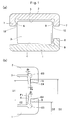
- roller bearing (hereinafter simply referred to as the "bearing") according to a first embodiment of the present invention is described with reference to the drawings. As shown in Fig. 1(a) , this bearing includes an inner race 1, an outer race 2, and a plurality of rollers 3.
- the inner race 1 is an annular member formed with a raceway 4 and a first flange 6.
- the outer race 2 is an annular member formed with a raceway 5 and second flanges 7.
- the first flange 6 and the second flanges 7 are hereinafter simply referred to as the "flange 6" and the "flanges 7", respectively.
- the flanges 6 and 7 may comprise flange rings.
- the rollers 3 are cylindrical rollers.
- a thrust load applied rightwardly in Fig. 1 to the bearing can be received by the flange 6, which is on one side of the inner raceway 4, and the right-hand one of the flanges 7, which are on both sides of the outer raceway 5.
- a thrust load applied leftwardly in Fig. 1 to the bearing can be received by the left-hand one of the flanges 7.
- Figs. 1(a) and 1(b) are sections of the bearing taken along the plane including the center axis of the bearing and the center axis of one of the rollers, with the roller 3 neither skewed nor tilted and with the end surfaces of the roller 3 facing the flanges 6 and 7 through oil film disposed therebetween.
- the gaps between the end surfaces of the roller 3 and the flanges 6 and 7 are shown in an exaggerated manner.
- the flanges 6 and 7 have annular guiding surfaces 9 and 10, respectively, which are annular side surfaces of the flanges 6 and 7 whose centers lie on the axis of the bearing.
- the roller 3 has annular guided surface portions 8, which are portions of the end surfaces of the roller 3 whose centers lie on the center axis of the bearing.
- the annular guided surface portions 8 can be brought into contact with the annular guiding surfaces 9 and 10 in the thrust direction while the roller 3 is rolling around the center axis of the bearing between the raceways 4 and 5.
- the annular guided surface portions 8, which are portions of the end surfaces of the roller 3 and can be brought into contact with the flanges 6 and 7, are each inclined obliquely, with respect to the direction perpendicular to the center axis of the roller, in the thrust direction toward the longitudinal center of the roller, from its edge E1 near the center axis of the roller to its edge E2 near the raceways 4 and 5, such that the diameter D1 (shown in Fig. 1(b) ) of its circumference, whose center lies on the center axis of the roller, is small.
- each of the annular guided surface portions 8 each extend in a straight line on any plane including the center axis of the bearing. That is, each of the annular guided surface portions 8 is a single conical surface whose center lies on the center axis of the roller.
- the annular guiding surfaces 9 and 10 of the flanges 6 and 7, which can contact the annular guided surface portions 8, are each inclined obliquely with respect to the radial direction and outwardly of the bearing with respect to the thrust direction, from its edge E3 near the raceway 4 or 5 to its edge E4 near the center axis of the roller, such that the diameter (D2 or D3) of its circumference, whose center lies on the center axis of the bearing, changes. That is, the flange 6 of the inner race 1 is shaped such that the diameter D2 increases, while the flanges 7 of the outer race 2 are shaped such that the diameter D3 decreases.
- each of the annular guiding surfaces 9 and 10 each extend in a straight line on any plane including the center axis of the bearing. That is, each of the annular guiding surfaces 9 and 10 is a single conical surface whose center lies on the center axis of the bearing.
- ⁇ i refers to the angle of the straight line connecting the edges E3 and E4 of the annular guiding surface 9 of the flange 6 relative to the radial direction, which is 0° or over and 90° or less. If the angle ⁇ i is an acute angle, this angle is referred to as “flange angle ⁇ i”.
- ⁇ o refers to the angle of the straight line connecting the edges E3 and E4 of the annular guiding surface 10 of each flange 7 relative to the radial direction, which is 0° or over and 90° or less. If the angle ⁇ o is an acute angle, this angle is referred to as “flange angle ⁇ o".
- the angle between the radial line and the line connecting the edges E1 and E2, which is an acute angle is referred to as "roller end surface angle ⁇ r".
- Equation 1 is known as Dowson-Higginson equation, which is used to calculate an oil film thickness during line contact of elastohydrodynamic lubrication theory. Based on this equation, optimum ranges of the flange angles ⁇ i and ⁇ o and roller end surface angle ⁇ r were considered. In particular, oil film thicknesses were calculated between the contact portions of the roller 3 and the respective flanges 6 and 7 (between the annular guided surface portions 8 and the annular guiding surfaces 10) to estimate the radial distribution of oil film thicknesses.
- h min R 2.65 ⁇ ⁇ 0 ⁇ u ⁇ ER 0.7 ⁇ ⁇ ⁇ E 0.54 ⁇ w ER - 0.13
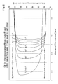
- Fig. 2 shows the results of calculation where the flange angle ⁇ i is equal to the roller end surface angle ⁇ r.
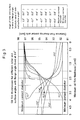
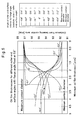
- Figs 3 to 5 show the results of calculation where the flange angle ⁇ i differs from the roller end surface angle ⁇ r.
- the limits of the radial range within which the annular guiding surface 9 of Fig. 1 can contact the annular guided surface portions 8 while the rollers are orbiting are determined by the positions of the edges E3 and E4 of the annular guided surface portion 8, irrespective of the contact length of the surfaces 9 and 8, tilt of the roller 3, or existence or non-existence of skew.
- the flange angles ⁇ i and ⁇ o and the roller end surface angle ⁇ r are preferably set at not less than 0.1° and not more than 1.5° over the entire circumference of each of the annular guiding surfaces 9 and 10 and the annular guided surface portion 8. If at least one of the roller end surface angle ⁇ r and the flange angle ⁇ i, ⁇ o is less than 0.1°, no satisfactory oil film may form.
- the difference between the flange angle ⁇ i, ⁇ o and the roller end surface angle ⁇ r is preferably not less than -0.2° and not more than +0.3°, because with this arrangement, irrespective of whether the flange angle ⁇ i, ⁇ o is equal to or differs from the roller end surface angle ⁇ r, a satisfactory oil film forms at 70% or more of the radial range where the annular guided surface portions 8 can contact the annular guiding surfaces 9 and 10.
- the flange angle ⁇ i, ⁇ o and the roller end surface angle ⁇ r are preferably equal to each other, that is, the difference between the flange angle ⁇ i, ⁇ o and the roller end surface angle ⁇ r is preferably zero degrees.
- each of the annular guiding surfaces 9 and 10 and the annular guided surface portions 8 so as to extend radially in straight lines inclined at the same inclination angle over the entire circumference thereof, it is possible to most effectively increase the line contact length.
- the angles ⁇ i and ⁇ o may be different from each other. According to the magnitude of thrust loads, whether the inner race is rotated or the outer race is rotated, and how lubricant is fed, the oil film forming ability and the necessary oil film thickness differ between the inner race 1 and the outer race 2.
- the flange angles ⁇ i and ⁇ o may be determined so as to satisfy the above-mentioned conditions only if lubrication is thin.
- the angles ⁇ i and ⁇ o may not necessarily have to be equal to each other.
- one of the flange angles ⁇ i and ⁇ o may be set at zero degrees.
- the flange angles ⁇ i and ⁇ o may be determined at different values so that one of the bearing parts (inner race 1 or outer race 2) of a conventional bearing can be used in the bearing according to the present invention.
- the bearing shown in Fig. 9 includes a conventional inner race or a conventional outer race, which has a flat annular surface extending parallel to a radial plane and thus having a flange angle ⁇ i or ⁇ o of zero degrees.
- Fig. 6 shows the second embodiment. What differs from the first embodiment is described below.
- the second embodiment differs from the first embodiment in that the annular guided surface portions 22 of the roller 21 are each formed with crowning.
- the annular guided surface portion 22 is connected to an end surface central portion 23 extending parallel to a plane perpendicular to the roller center axis through the edge E1, and is connected to a radially outer chamfer 24 through the edge E2.
- edge loads are generated between the edges E1 and E2 and the portions of the annular guiding surfaces 9 and 10 (see also Fig. 1 ) that are in contact with the edges E1 and E2.
- the annular guiding surfaces 9 and 10 are each connected to a grinding undercut through the edge E3, and connected to a flange radial surface chamfer through the edge E4. Edge loads are also generated between the edges E3 and E4 and the portions of the annular guided surface portion 22 that are in contact with the edges E3 and E4.
- the crowning also makes it possible for the annular guided surface portion 22 to more easily slide on the annular guiding surfaces 9 and 10 when the roller 21 is skewed or tilted. This reduces galling.
- the annular guided surface portion 22 and the annular guiding surfaces 9 and 10 is displaced from any straight line connecting the edges E1 and E2 or connecting the edges E3 and E4. Even if such displacement is slight, it is possible to effectively reduce stress.
- the crowning improves the oil film forming ability to substantially the same extent as when the roller end surface angle ⁇ r differs from the flange angles ⁇ i and ⁇ o as described above.
- crowning is not particularly limited.
- the crowning may be in the form of a circular arc-shaped surface, composite straight surfaces, or a combination thereof that are formed on each of the edges of the annular guided surface portion 22 and/or the annular guiding surfaces 9 and 10.
- crowning may be formed on the entire annular guided surface portion 22 and/or on the entire annular guiding surfaces 9 and 10.
- the crowning may be in the form of a circular arc-shaped surface, composite straight surfaces, or a combination thereof.
- Fig. 7 shows the third embodiment, which differs from the first embodiment in that the end surface of the roller 31 has a grinding undercut formed in the end surface central portion 33 surrounded by the edge E1 of the annular guided surface portion 32, which is located near the roller center axis.
- the grinding undercut reduces the number of steps for forming the roller end surface, and thus the cost.
- the end surface central portion 33 serves as an oil reservoir, lubricant flows into the space between the annular guided surface portion 32 and the annular guiding surfaces 9 and 10, thus improving lubrication of the contact portions of these surfaces.
- the relationship between the diametric ratios of the end surface central portion 33 and the annular guided surface portion 32, relative to the diameter of the roller, and the annular guiding surfaces 9 and 10 should be suitably determined taking into consideration the thrust load capacity and lubricating properties.
- the diameter of the end surface central portion 33 may be set at less than half the diameter of the roller 31, and the radial widths of the annular guiding surfaces 9 and 10 from the raceways 4 and 5 may be set at less than 15% of the diameter of the roller 31.
- the diameter of the end surface central portion 33 may be set at not less than 50% and not more than 80%, of the diameter of the roller 31, and the radial widths of the annular guiding surfaces 9 and 10 from the raceways 4 and 5 may be set at not less than 15% and not more than 25%, of the diameter of the roller 31 so as to prevent the contact oval from protruding from the annular guiding surfaces 9 and 10, while maximizing the radial contact range between the annular guided surface portion 32 and the annular guiding surfaces 9 and 10.
- Fig. 8 shows the fourth embodiment, which is a modification of the third embodiment, and differs therefrom in that an intermediate annular portion 44 is formed between the annular guided surface portion 42 and the end surface central portion 43, of each end surface of the roller 41 so as to extend parallel to a plane perpendicular to the roller center axis.
Landscapes
- Engineering & Computer Science (AREA)
- General Engineering & Computer Science (AREA)
- Mechanical Engineering (AREA)
- Rolling Contact Bearings (AREA)
Abstract
Description
- This invention relates to a roller bearing including flanges which can receive thrust loads.
- As one of this type of roller bearings,
Fig. 9 shows a standard cylindrical roller bearing. In this bearing,flanges 91 and aroller end surface 92 haveflat surface portions flat surface portions - In order to improve the thrust load capacity of bearing, it is necessary to prevent overheating and seizure due to excessive contact surface pressure between the roller end surfaces and the flanges while thrust loads are being applied. For this purpose, it is known to suitably determine the shapes of the surfaces of the flanges and the roller end surfaces so as to adjust the position and size of contact ovals (see the below-identified Patent document 1).
- In particular, the roller end surface has an annular guided surface portion which can contact a flange while the roller is orbiting, wherein the annular guided surface portion is inclined obliquely, in the thrust direction toward the longitudinal center of the roller, from its edge near the roller center axis to its edge near the raceway such that the circumference of the annular guided surface portion whose center lies on the roller center axis is small. The flange has an annular guiding surface which can contact the annular guided surface portion, wherein the annular guiding surface is inclined obliquely outwardly of the bearing with respect to the thrust direction, from its edge near the raceway to its edge near the roller center axis such that the circumference of the annular guiding surface whose center lies on the bearing center axis changes. With this arrangement, since the annular guided surface portion of the roller end surface and the annular guiding surface of the flange are inclined, the annular guided surface portion and the annular guiding surface are brought into point contact or line contact with each other, so that a gap forms between these surfaces, allowing lubricant to flow smoothly into between these surfaces. This in turn prevents overheating and seizure, thus improving the thrust load capacity of the bearing.
- In the bearing disclosed in
Patent document 1, the entire annular guided surface portion of the roller end surface is formed with crowning having a center of curvature located on the roller axis (whose radius of curvature is about 25 to 100 times the diameter of the roller). The crowning prevents excessive edge loads from being generated between the contact portions of the annular guided surface portion of the roller end surface and the annular guiding surface of the flange. By the combination of the radius of curvature and an acute inclination angle (about 0.15 to 0.65°) of the flange relative to the direction perpendicular to the roller center axis, it is possible to adjust the position and size of the contact oval. - Patent document 1:
JP Patent Publication 2002-195272A - In the above arrangement, although lubricant can flow smoothly, since it is necessary to operate the bearing while keeping the contact surface pressure between the annular guided surface portion of the roller end surface and the annular guiding surface of the flange within such a range that an oil film is present therebetween, there is a limit to the ability to support thrust loads. Particularly in the arrangement of
Patent document 1, in which the annular guided surface portion of the roller and the annular guiding surface of the flange are shaped such that they are brought into point contact with each other, the maximum contact surface pressure tends to be much higher than with standard bearings, so that the upper limit of the thrust load capacity of this bearing is low. - An object of the present invention is to improve the oil film forming ability at the contact portion between the roller end surface and the flange, of a bearing of the type in which thrust loads are received by the flange.
- According to this invention, this object is achieved in a roller bearing wherein a roller has an end surface having an annular guided surface portion which can contact a flange, wherein the annular guided surface portion is inclined obliquely, with respect to the direction perpendicular to the center axis of the roller, in the thrust direction toward the longitudinal center of the roller, from its edge near the roller center axis to its edge near the raceway such that the circumference of the annular guided surface portion whose center lies on the roller center axis is small, wherein the flange has an annular guiding surface which can contact the annular guided surface portion, wherein the annular guiding surface is inclined obliquely with respect to the radial direction and outwardly of the bearing with respect to the thrust direction, from its edge near the raceway to its edge near the roller center axis such that the circumference of the annular guiding surface whose center lies on the bearing center axis changes, and wherein the flange can receive thrust loads. As described above, with this arrangement, lubricant can smoothly flow into the contact portion between the roller end surface and the flange. As used herein, the "thrust" direction refers to the direction parallel to the bearing center axis.
- When the annular guided surface portion of the roller is guided by the annular guiding surface of the flange in the circumferential direction about the bearing center axis, the annular guided surface portion and the annular guiding surface are in rolling contact and sliding contact at a high contact surface pressure. Thus, it is possible to calculate the oil film thickness at any radial position of the contact portion between the annular guided surface portion and the annular guiding surface by numerical analysis based on the elastohydrodynamic lubrication (EHL) theory. The inventor tried to discover a combination of a flange angle and a roller end surface angle which leads to the formation of a satisfactory oil film by the above numerical analysis, in which the flange angle and the roller end surface angle are an acute angle between a radial straight line and a straight line passing through the edges of the annular guiding surface, and an acute angle between a radial straight line and a straight line passing through the edges of the annular guided surface portions, on the plane including the bearing center axis and the roller center axis of the roller. The "radial" direction refers to a direction perpendicular to the bearing center axis.
- As a result, according to the present invention, the flange angle and the roller end surface angle are both set to be not less than 0.1° and not more than 1.5° over the entire circumferences of the annular guiding surface and the annular guided surface portion. With this arrangement, a satisfactory oil film forms at 70% or more of the radial range where the annular guiding surface can contact the annular guided surface portion in the thrust direction. If one of the flange angle and the roller end surface angle is less than 0.1°, no satisfactory oil film may form. If one of the flange angle and the roller end surface angle is larger than 1.5°, the projected areas of the annular guiding surface and the annular guided surface portions in the thrust direction decrease, which in turn increases the load per unit width and the oil film forming ability, thus increasing the thrust load capacity and the amount of material that has to be removed.
- The difference between the flange angle and the roller end surface angle is preferably not less than -0.2° and not more than +0.3°. With this arrangement, irrespective of whether these angles are the same or different from each other, a satisfactory oil film forms at 70% or more of the radial range.
- It is particularly preferable that the difference between the flange angle and the roller end surface angle is zero degrees. With this arrangement, since the annular guided surface portion and the annular guiding surface are shaped such that they can be brought into line contact with each other over the entire radial range thereof. This improves the thrust load capacity compared to bearings in which the annular guided surface portion and the annular guiding surface are brought into point contact with each other.
- Preferably, each of the annular guided surface portion and the annular guiding surface extend in a straight line on any plane including the center axis of the bearing. With this arrangement, since the annular guided surface portion and the annular guiding surface are both simple conical surfaces, the difference between the flange angle and the roller end surface angle can be set easily.
- Preferably, at least one of the annular guided surface portion and the annular guiding surface is formed with crowning. With this arrangement, edge loads decreases, so that it is possible to reduce galling of the annular guided surface portion and the annular guiding surface when the roller is skewed or tilted.
- Preferably, the end surface of the roller has a central portion formed with a grinding undercut. Such an undercut reduces the number of steps for forming the roller end surface, and thus the cost. Also, the end surface central portion serves as an oil reservoir, thus improving lubrication of the contact portions of the annular guided surface portion and the annular guiding surface.
- Preferably, the end surface of the roller has an intermediate annular portion extending parallel to a plane perpendicular to the roller center axis, between the annular guided surface portion and the central portion. With this arrangement, the length of the roller can be measured and controlled easily with reference to the intermediate annular portion.
- This roller bearing may be configured such that a first flange is provided on an inner race and a second flange is provided on an outer race, the first flange has a first annular guiding surface which can contact the end surface of the roller and which has edges, the first annular guiding surface has a first angle which is not less than 0° and not more than 90° and formed between a radial straight line and the straight line passing through the edges of the first annular guiding surface, on the plane including the center axis of the bearing and the center axis of the roller, the second flange has a second annular guiding surface which can contact the end surface of the roller and which has edges, the second annular guiding surface has a second angle which is not less than 0° and not more than 90° and formed between a radial straight line and the straight line passing through the edges of the second annular guiding surface, at least one of the first and second angles is the flange angle, and the first and second angles differ from each other.
- This invention is especially advantageously applicable to a cylindrical roller bearing, of which the roller is a cylindrical roller.
- With the above-described arrangement, in the roller bearing according to the present invention, of which a flange can receive thrust loads, an oil film forming ability improves between the annular guided surface portion and the annular guiding surface, where the roller end surface contacts the flange.
-
-
Fig. 1(a) is a sectional view of a roller bearing according to a first embodiment of the present invention; andFig. 1(b) is a conceptual view of the first embodiment, showing a flange angle and a roller end surface angle. -
Fig. 2 is a graph showing calculation results of oil film thicknesses when the flange angle and the roller end surface angle are changed to various values with the flange angle and the roller end surface kept equal to each other. -
Fig. 3 is a graph showing calculation results of oil film thicknesses for various roller end surface angles with the flange angle set at 0.4°. -
Fig. 4 is a graph showing calculation results of oil film thicknesses for various roller end surface angles with the flange angle set at 0.6°. -
Fig. 5 is a graph showing calculation results of oil film thicknesses for various roller end surface angles with the flange angle set at 0.8°. -
Fig. 6 is a partial sectional view of a roller according to a second embodiment. -
Fig. 7 is a partial sectional view of a roller according to a third embodiment. -
Fig. 8 is a partial sectional view of a roller according to a fourth embodiment. -
Fig. 9 is a sectional view of a conventional cylindrical roller bearing. - A roller bearing (hereinafter simply referred to as the "bearing") according to a first embodiment of the present invention is described with reference to the drawings. As shown in
Fig. 1(a) , this bearing includes aninner race 1, anouter race 2, and a plurality ofrollers 3. - The
inner race 1 is an annular member formed with araceway 4 and afirst flange 6. Theouter race 2 is an annular member formed with araceway 5 andsecond flanges 7. Thefirst flange 6 and thesecond flanges 7 are hereinafter simply referred to as the "flange 6" and the "flanges 7", respectively. Theflanges - The
rollers 3 are cylindrical rollers. - A thrust load applied rightwardly in
Fig. 1 to the bearing can be received by theflange 6, which is on one side of theinner raceway 4, and the right-hand one of theflanges 7, which are on both sides of theouter raceway 5. A thrust load applied leftwardly inFig. 1 to the bearing can be received by the left-hand one of theflanges 7. -
Figs. 1(a) and 1(b) are sections of the bearing taken along the plane including the center axis of the bearing and the center axis of one of the rollers, with theroller 3 neither skewed nor tilted and with the end surfaces of theroller 3 facing theflanges roller 3 and theflanges - The
flanges annular guiding surfaces flanges roller 3 has annular guidedsurface portions 8, which are portions of the end surfaces of theroller 3 whose centers lie on the center axis of the bearing. The annular guidedsurface portions 8 can be brought into contact with theannular guiding surfaces roller 3 is rolling around the center axis of the bearing between theraceways - The annular guided
surface portions 8, which are portions of the end surfaces of theroller 3 and can be brought into contact with theflanges raceways Fig. 1(b) ) of its circumference, whose center lies on the center axis of the roller, is small. - The annular guided
surface portions 8 each extend in a straight line on any plane including the center axis of the bearing. That is, each of the annular guidedsurface portions 8 is a single conical surface whose center lies on the center axis of the roller. - The
annular guiding surfaces flanges surface portions 8, are each inclined obliquely with respect to the radial direction and outwardly of the bearing with respect to the thrust direction, from its edge E3 near theraceway flange 6 of theinner race 1 is shaped such that the diameter D2 increases, while theflanges 7 of theouter race 2 are shaped such that the diameter D3 decreases. - The
annular guiding surfaces annular guiding surfaces - As used herein, "θi" refers to the angle of the straight line connecting the edges E3 and E4 of the
annular guiding surface 9 of theflange 6 relative to the radial direction, which is 0° or over and 90° or less. If the angle θi is an acute angle, this angle is referred to as "flange angle θi". "θo" refers to the angle of the straight line connecting the edges E3 and E4 of theannular guiding surface 10 of eachflange 7 relative to the radial direction, which is 0° or over and 90° or less. If the angle θo is an acute angle, this angle is referred to as "flange angle θo". The angle between the radial line and the line connecting the edges E1 and E2, which is an acute angle, is referred to as "roller end surface angle θr". -
Equation 1 below is known as Dowson-Higginson equation, which is used to calculate an oil film thickness during line contact of elastohydrodynamic lubrication theory. Based on this equation, optimum ranges of the flange angles θi and θo and roller end surface angle θr were considered. In particular, oil film thicknesses were calculated between the contact portions of theroller 3 and therespective flanges 6 and 7 (between the annular guidedsurface portions 8 and the annular guiding surfaces 10) to estimate the radial distribution of oil film thicknesses.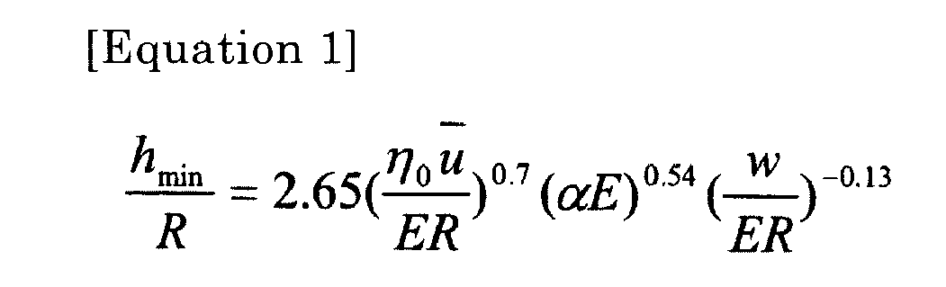
where - hmin is the minimum oil film thickness;
- η 0 is the viscosity under the atmospheric pressure;
-
u is the average rolling speed; - α is the viscosity-pressure coefficient;
- w is the load per unit width
- R is the equivalent radius of curvature; and
- E is the modulus of longitudinal elasticity
-
Fig. 2 shows the results of calculation where the flange angle θi is equal to the roller end surface angle θr.Figs 3 to 5 show the results of calculation where the flange angle θi differs from the roller end surface angle θr. These calculation models are based on the assumption that the bearing measures 140 mm in inner diameter, 300 mm in outer diameter and 102 mm wide, and a thrust load of about 1650 [N] is applied to the bearing. - The limits of the radial range within which the
annular guiding surface 9 ofFig. 1 can contact the annular guidedsurface portions 8 while the rollers are orbiting are determined by the positions of the edges E3 and E4 of the annular guidedsurface portion 8, irrespective of the contact length of thesurfaces roller 3, or existence or non-existence of skew. Thus, in the respective calculation models ofFig. 2 , where theannular guiding surface 9 is in line contact with the annular guidedsurface portion 8 because the flange angle θi and roller end surface angle θr are equal to each other, and where the angles θi and θr are within the range of 0.1 to 1.5°, the radiuses (r1 and r2) of the inner and outer limit positions of the contact surface with respect to the radial direction of the bearing correspond to the radiuses of the respective (circular) edges E3 and E4. In the respective calculation models ofFigs. 3 to 5 too, where theannular guiding surface 9 is in line contact with the annular guidedsurface portion 8 because the flange angle θi and roller end surface angle θr (ofFig. 1 ) differ from each other, so that due to tilting of the roller, the contact position of the roller on theannular guiding surface 9 changes to a relatively large extent in the radial direction, and where θi = 0.4° and θr = 0.1 to 0.8° inFig. 3 , θi = 0.6° and θr = 0.2 to 1.0° inFig. 4 , and θi = 0.8° and θr = 0.4 to 1.2° inFig. 5 , the radiuses (r3 and r4) of the inner and outer limit positions of the contact surface with respect to the radial direction of the bearing correspond to the radiuses of the respective (circular) edges E3 and E4. - If the oil film parameter A of the
below Equation 2, which is based on the relationship between the oil film thickness and the surface roughness, is 3 or larger, lubrication is considered to be sufficient with a sufficient oil film formed. If the annular guided surface portions and the annular guiding surfaces of a bearing have ordinary surface roughness, and the minimum oil film thickness is 1.5 µm, the parameter A will be 3 or over.
where: - hmin is a minimum oil film thickness; and
- σ1 and σ2 are average surface roughness values of two objects
- From the oil film thickness distributions in the calculation models shown in
Fig. 2 , it is apparent that the oil film thickness is 1.5 µm or larger at 70% or more of the radial range (r2) - (r1), where the roller end surface can contact the flange. This in turn indicates that if the flange angle θi and the roller end surface angle θr (shown inFig. 1 ) are equal to each other, oil film forms satisfactorily between theannular guiding surface 9 and the annular guidedsurface portion 8, provided the angles θi and θr are not less than 0.1° and not more than 1.5°. - From the oil film thickness distributions in the calculation models shown in
Figs. 3 to 5 , where the flange angle θi differs from the roller end surface angle θr, it is apparent that for the calculation models where difference between the flange angle θi and the roller end surface angle θr (relative angle) is not less than -0.2° and not more than +0.3°, the oil film thickness is 1.5 µm or larger at 70% or more of the radial range (r4) - (r3), where the roller end surface can contact the flange. This indicates that even if the flange angle θi and the roller end surface angle θr (shown inFig. 1 ) differ from each other, oil film forms satisfactorily between theannular guiding surface 9 and the annular guidedsurface portion 8, provided the difference between the flange angle θi and the roller end surface angle θr is not less than -0.2° and not more than +0.3°. - Similar oil film distributions are also obtained for the combination of the flange angle θo of the
flange 7 and the roller end surface angle θr. Thus, considering the above results of analysis, the flange angles θi and θo and the roller end surface angle θr are preferably set at not less than 0.1° and not more than 1.5° over the entire circumference of each of theannular guiding surfaces surface portion 8. If at least one of the roller end surface angle θr and the flange angle θi, θo is less than 0.1°, no satisfactory oil film may form. If at least one of the roller end surface angle θr and the flange angle θi, θo is larger than 1.5°, no satisfactory oil film may form either, because the areas of the annular guidedsurface portions 8 and theannular guiding surfaces - Further, the difference between the flange angle θi, θo and the roller end surface angle θr is preferably not less than -0.2° and not more than +0.3°, because with this arrangement, irrespective of whether the flange angle θi, θo is equal to or differs from the roller end surface angle θr, a satisfactory oil film forms at 70% or more of the radial range where the annular guided
surface portions 8 can contact theannular guiding surfaces - Still further, in order to maximize the line contact length between the
annular guiding surfaces surface portions 8, and thereby to maximize the thrust load capacity, the flange angle θi, θo and the roller end surface angle θr are preferably equal to each other, that is, the difference between the flange angle θi, θo and the roller end surface angle θr is preferably zero degrees. Especially by forming, as inFig. 1(b) , each of theannular guiding surfaces surface portions 8 so as to extend radially in straight lines inclined at the same inclination angle over the entire circumference thereof, it is possible to most effectively increase the line contact length. - In a bearing having a
flange 6 on theinner race 1 and havingflanges 7 on the outer race 2 (seeFig. 1 ), if at least one of the flange angles θi and θo is determined in the above-described manner, the angles θi and θo may be different from each other. According to the magnitude of thrust loads, whether the inner race is rotated or the outer race is rotated, and how lubricant is fed, the oil film forming ability and the necessary oil film thickness differ between theinner race 1 and theouter race 2. The flange angles θi and θo may be determined so as to satisfy the above-mentioned conditions only if lubrication is thin. Thus, the angles θi and θo may not necessarily have to be equal to each other. Under favorable lubricating conditions, one of the flange angles θi and θo may be set at zero degrees. The flange angles θi and θo may be determined at different values so that one of the bearing parts (inner race 1 or outer race 2) of a conventional bearing can be used in the bearing according to the present invention. For example, the bearing shown inFig. 9 includes a conventional inner race or a conventional outer race, which has a flat annular surface extending parallel to a radial plane and thus having a flange angle θi or θo of zero degrees. -
Fig. 6 shows the second embodiment. What differs from the first embodiment is described below. The second embodiment differs from the first embodiment in that the annular guidedsurface portions 22 of theroller 21 are each formed with crowning. The annular guidedsurface portion 22 is connected to an end surfacecentral portion 23 extending parallel to a plane perpendicular to the roller center axis through the edge E1, and is connected to a radiallyouter chamfer 24 through the edge E2. When a thrust load is applied, edge loads are generated between the edges E1 and E2 and the portions of theannular guiding surfaces 9 and 10 (see alsoFig. 1 ) that are in contact with the edges E1 and E2. Theannular guiding surfaces surface portion 22 that are in contact with the edges E3 and E4. By providing the annular guidedsurface portion 22 and/or theannular guiding surfaces surface portion 22 to more easily slide on theannular guiding surfaces roller 21 is skewed or tilted. This reduces galling. - By forming crowning, the annular guided
surface portion 22 and theannular guiding surfaces - The shape of crowning is not particularly limited. For example, as shown in
Fig. 6 , the crowning may be in the form of a circular arc-shaped surface, composite straight surfaces, or a combination thereof that are formed on each of the edges of the annular guidedsurface portion 22 and/or theannular guiding surfaces Fig. 9 , crowning may be formed on the entire annular guidedsurface portion 22 and/or on the entireannular guiding surfaces -
Fig. 7 shows the third embodiment, which differs from the first embodiment in that the end surface of theroller 31 has a grinding undercut formed in the end surfacecentral portion 33 surrounded by the edge E1 of the annular guidedsurface portion 32, which is located near the roller center axis. The grinding undercut reduces the number of steps for forming the roller end surface, and thus the cost. Also, since the end surfacecentral portion 33 serves as an oil reservoir, lubricant flows into the space between the annular guidedsurface portion 32 and theannular guiding surfaces - The relationship between the diametric ratios of the end surface
central portion 33 and the annular guidedsurface portion 32, relative to the diameter of the roller, and theannular guiding surfaces central portion 33 from facing theannular guiding surfaces central portion 33 may be set at less than half the diameter of theroller 31, and the radial widths of theannular guiding surfaces raceways roller 31. Alternatively, as disclosed inPatent document 1, the diameter of the end surfacecentral portion 33 may be set at not less than 50% and not more than 80%, of the diameter of theroller 31, and the radial widths of theannular guiding surfaces raceways roller 31 so as to prevent the contact oval from protruding from theannular guiding surfaces surface portion 32 and theannular guiding surfaces -
Fig. 8 shows the fourth embodiment, which is a modification of the third embodiment, and differs therefrom in that an intermediateannular portion 44 is formed between the annular guidedsurface portion 42 and the end surfacecentral portion 43, of each end surface of theroller 41 so as to extend parallel to a plane perpendicular to the roller center axis. With this arrangement, since the length of theroller 41 can be measured with reference to the surface portions whose axial positions are uniform (end surface central portion 43), the length of theroller 41 can be measured and controlled more easily than when the length of theroller 41 is measured with reference to linear portions shown inFig. 7 (edges E1 of the annular guided surface portions 32). - The present invention includes all modifications covered by the claims.
-
- 1.
- Inner race
- 2.
- Outer race
- 3, 21, 31, 41.
- Roller
- 4, 5.
- Raceway
- 6.
- First flange
- 7.
- Second flange
- 8, 22, 32, 42.
- Annular guided surface portion
- 9, 10.
- Annular guiding surface
- 23, 33, 43.
- Roller end surface central portion
- 44.
- Intermediate annular portion
Claims (9)
- A roller bearing wherein a roller (3) has an end surface having an annular guided surface portion (8) which can contact a flange (6, 7), wherein the annular guided surface portion (8) is inclined obliquely, with respect to a direction perpendicular to a center axis of the roller, in a thrust direction toward a longitudinal center of the roller, from a first edge (E1) of the annular guided surface portion near the center axis of the roller to a second edge (E2) of the annular guided surface portion near a raceway (4, 5), whereby a circumference of the annular guided surface portion whose center lies on the center axis of the roller is small,
wherein the flange (6, 7) has an annular guiding surface (9, 10) which can contact the annular guided surface portion (8), wherein the annular guiding surface (9, 10) is inclined obliquely with respect to a radial direction and outwardly of the bearing with respect to the thrust direction, from a third edge (E3) of the annular guiding surface near the raceway (4, 5) to a fourth edge (E4) of the annular guiding surface near the center axis of the roller, whereby a circumference of the annular guiding surface whose center lies on a center axis of the bearing changes, and
wherein the flange (6, 7) can receive thrust loads,
characterized in that the annular guiding surface (9, 10) has a flange angle (θi, θo) which is an acute angle between a radial straight line and a straight line passing through the third and fourth edges (E3 and E4), on a plane including the center axis of the bearing and the center axis of the roller, and the annular guided surface portion (8) has a roller end surface angle (θr) which is an acute angle between a radial straight line and a straight line passing through the first and second edges (E1 andE2), on the plane including the center axis of the bearing and the center axis of the roller, wherein the flange angle (θi, θo) and the roller end surface angle (θr) are both not less than 0.1° and not more than 1.5° over the entire circumferences of the annular guiding surface (9, 10) and the annular guided surface portion (8), respectively. - The roller bearing of claim 1, wherein a difference between the flange angle (θi, θo) and the roller end surface angle (θr) is not less than -0.2° and not more than +0.3°.
- The roller bearing of claim 2, wherein a difference between the flange angle (θi, θo) and the roller end surface angle (θr) is zero degrees.
- The roller bearing of claim 2 or 3, wherein each of the annular guided surface portion (8) and the annular guiding surface (9, 10) extend in a straight line on any plane including the center axis of the bearing.
- The roller bearing of any of claims 1 to 3, wherein at least one of the annular guided surface portion (22) and the annular guiding surface (9, 10) is formed with crowning.
- The roller bearing of any of claims 1 to 5, wherein the end surface of the roller has a central portion (33) formed with a grinding undercut.
- The roller bearing of claim 6, wherein the end surface of the roller has an intermediate annular portion extending parallel to a plane perpendicular to the center axis of the roller, between the annular guided surface portion (42) and the central portion (43).
- The roller bearing of any of claims 1 to 7, wherein a first flange (6) is provided on an inner race (1) and a second flange (7) is provided on an outer race (2),
wherein the first flange (6) has a first annular guiding surface (9) which can contact the end surface of the roller (3) and which has edges (E3 and E4), wherein the first annular guiding surface (9) has a first angle (θi) which is not less than 0° and not more than 90° and formed between a radial straight line and a straight line passing through the edges (E3 and E4) of the first annular guiding surface (9), on a plane including the center axis of the bearing and the center axis of the roller, wherein the second flange (7) has a second annular guiding surface (10) which can contact the end surface of the roller (3) and which has edges (E3 and E4), wherein the second annular guiding surface (10) has a second angle (θi) which is not less than 0° and not more than 90° and formed between a radial straight line and a straight line passing through the edges (E3 and E4) of the second annular guiding surface (10), wherein at least one of the first and second angles (θi and θo) is the flange angle (θi, θo), and wherein the first and second angles (θi and θo) differ from each other. - The roller bearing of any of claims 1 to 8, wherein the roller (3) is a cylindrical roller.
Applications Claiming Priority (2)
| Application Number | Priority Date | Filing Date | Title |
|---|---|---|---|
| JP2011264529A JP2013117249A (en) | 2011-12-02 | 2011-12-02 | Roller bearing |
| PCT/JP2012/079933 WO2013080824A1 (en) | 2011-12-02 | 2012-11-19 | Roller bearing |
Publications (2)
| Publication Number | Publication Date |
|---|---|
| EP2787225A1 true EP2787225A1 (en) | 2014-10-08 |
| EP2787225A4 EP2787225A4 (en) | 2015-06-03 |
Family
ID=48535286
Family Applications (1)
| Application Number | Title | Priority Date | Filing Date |
|---|---|---|---|
| EP12854417.8A Withdrawn EP2787225A4 (en) | 2011-12-02 | 2012-11-19 | Roller bearing |
Country Status (6)
| Country | Link |
|---|---|
| US (1) | US9011018B2 (en) |
| EP (1) | EP2787225A4 (en) |
| JP (1) | JP2013117249A (en) |
| CN (1) | CN104011410A (en) |
| IN (1) | IN2014CN04878A (en) |
| WO (1) | WO2013080824A1 (en) |
Families Citing this family (7)
| Publication number | Priority date | Publication date | Assignee | Title |
|---|---|---|---|---|
| CN105090236B (en) * | 2014-04-15 | 2019-07-12 | 舍弗勒技术股份两合公司 | Cylindrical Roller Bearings |
| CN107110301A (en) * | 2015-01-08 | 2017-08-29 | 谐波传动系统有限公司 | Wavegenerator and Wave gear device |
| ES3000418T3 (en) * | 2017-04-26 | 2025-02-28 | Timken Co | Non-elliptical contact profile for cylindrical roller bearing |
| DE102019220284A1 (en) | 2019-12-19 | 2021-06-24 | Aktiebolaget Skf | Rolling bearings with wire races |
| DE102019220292A1 (en) * | 2019-12-19 | 2021-06-24 | Aktiebolaget Skf | Rolling bearings with wire races and retaining rib |
| JP7498593B2 (en) * | 2020-04-30 | 2024-06-12 | Ntn株式会社 | Wheel bearing device |
| JPWO2022209598A1 (en) * | 2021-03-31 | 2022-10-06 |
Family Cites Families (18)
| Publication number | Priority date | Publication date | Assignee | Title |
|---|---|---|---|---|
| US3350147A (en) * | 1966-02-01 | 1967-10-31 | Skf Ind Inc | Rolling bearing assembly |
| SE349368B (en) * | 1970-11-16 | 1972-09-25 | Skf Ind Trading & Dev | |
| US3963285A (en) * | 1973-10-09 | 1976-06-15 | Skf Industries, Inc. | Cage control of skew angle in roller bearings |
| US4027930A (en) * | 1975-12-19 | 1977-06-07 | The Garrett Corporation | Bearing assembly and method |
| JPS5843609B2 (en) * | 1975-12-26 | 1983-09-28 | 日本精工株式会社 | Korojikuuke |
| JPS5913369Y2 (en) * | 1979-07-18 | 1984-04-20 | 日本精工株式会社 | cylindrical roller bearing |
| JPS59106719A (en) * | 1982-12-08 | 1984-06-20 | Koyo Seiko Co Ltd | Cylindrical roller bearing |
| JPH0712119A (en) * | 1993-06-28 | 1995-01-17 | Nippon Seiko Kk | Cylindrical roller bearing |
| JP2000304038A (en) * | 1999-04-20 | 2000-10-31 | Nsk Ltd | Roller bearing |
| RU2199039C2 (en) * | 2000-06-19 | 2003-02-20 | Открытое акционерное общество "Минский подшипниковый завод" | Single-row spherical roller bearing |
| JP2002195272A (en) | 2000-12-27 | 2002-07-10 | Nsk Ltd | Flanged cylindrical roller bearing |
| JP2003021145A (en) * | 2001-07-05 | 2003-01-24 | Nsk Ltd | Roller bearing |
| CN100375853C (en) * | 2001-11-06 | 2008-03-19 | 日本精工株式会社 | Radial roller bearing |
| JP2004353744A (en) * | 2003-05-28 | 2004-12-16 | Nsk Ltd | Roller bearing |
| WO2004111477A1 (en) * | 2003-06-12 | 2004-12-23 | Nsk Ltd. | Cylindrical roller bearing |
| JP5455329B2 (en) * | 2008-06-24 | 2014-03-26 | Ntn株式会社 | Cylindrical roller bearing |
| JP5595747B2 (en) * | 2010-02-10 | 2014-09-24 | Ntn株式会社 | Wheel bearing device |
| DE102010018553A1 (en) * | 2010-04-28 | 2012-01-19 | Aktiebolaget Skf | Roller and roller bearings |
-
2011
- 2011-12-02 JP JP2011264529A patent/JP2013117249A/en active Pending
-
2012
- 2012-11-19 US US14/361,316 patent/US9011018B2/en not_active Expired - Fee Related
- 2012-11-19 CN CN201280059184.8A patent/CN104011410A/en active Pending
- 2012-11-19 WO PCT/JP2012/079933 patent/WO2013080824A1/en not_active Ceased
- 2012-11-19 EP EP12854417.8A patent/EP2787225A4/en not_active Withdrawn
-
2014
- 2014-06-27 IN IN4878CHN2014 patent/IN2014CN04878A/en unknown
Also Published As
| Publication number | Publication date |
|---|---|
| US9011018B2 (en) | 2015-04-21 |
| CN104011410A (en) | 2014-08-27 |
| EP2787225A4 (en) | 2015-06-03 |
| IN2014CN04878A (en) | 2015-09-18 |
| WO2013080824A1 (en) | 2013-06-06 |
| US20140328554A1 (en) | 2014-11-06 |
| JP2013117249A (en) | 2013-06-13 |
Similar Documents
| Publication | Publication Date | Title |
|---|---|---|
| US9011018B2 (en) | Roller bearing | |
| US9593718B2 (en) | Multipoint contact ball bearing | |
| US20110116734A1 (en) | Punched retainer, self-aligning roller bearing, and method of manufacturing punched retainer | |
| US10330146B2 (en) | Retainer and tapered roller bearing | |
| US9683605B2 (en) | Tapered roller bearing | |
| US9243664B2 (en) | Toroidal roller bearing | |
| US9618043B2 (en) | Roller bearing flange configuration | |
| EP1947356A2 (en) | Cage for rolling bearing and rolling bearing having the same | |
| US20040240764A1 (en) | Roller bearing | |
| KR101827022B1 (en) | Sliding bearing shell | |
| US10190624B2 (en) | Spacer device, toroidal roller bearing and method | |
| JP2007051703A (en) | Tapered roller bearing and transmission bearing device using the same | |
| EP3411600B1 (en) | Roller bearing with enhanced roller-end and flange contact | |
| US10197094B2 (en) | Double-row spherical roller bearing | |
| EP3022454B1 (en) | Roller bearing with a crowning/arcuate contact line | |
| US7934873B2 (en) | Tapered roller bearing | |
| US12117042B2 (en) | Roller bearing, roller bearing unit, motor, method for manufacturing roller bearing, and method for silencing roller bearing | |
| EP2628967A1 (en) | Loose C-shaped spacing body forming a pocket to accomodate a roller, in particular for a thrust roller bearing of a tunnel boring machine | |
| JP2010156425A (en) | Self-aligning roller bearing | |
| EP2628966A1 (en) | Loose spacing body for a roller bearing with protrusions to guide the spacing body with low friction | |
| JP2007315450A (en) | Low temperature rise type spherical roller bearing | |
| CN107461408A (en) | roller bearing |
Legal Events
| Date | Code | Title | Description |
|---|---|---|---|
| PUAI | Public reference made under article 153(3) epc to a published international application that has entered the european phase |
Free format text: ORIGINAL CODE: 0009012 |
|
| 17P | Request for examination filed |
Effective date: 20140630 |
|
| AK | Designated contracting states |
Kind code of ref document: A1 Designated state(s): AL AT BE BG CH CY CZ DE DK EE ES FI FR GB GR HR HU IE IS IT LI LT LU LV MC MK MT NL NO PL PT RO RS SE SI SK SM TR |
|
| DAX | Request for extension of the european patent (deleted) | ||
| RA4 | Supplementary search report drawn up and despatched (corrected) |
Effective date: 20150504 |
|
| RIC1 | Information provided on ipc code assigned before grant |
Ipc: F16C 19/36 20060101AFI20150424BHEP Ipc: F16C 33/34 20060101ALI20150424BHEP Ipc: F16C 19/26 20060101ALI20150424BHEP Ipc: F16C 33/58 20060101ALI20150424BHEP Ipc: F16C 33/66 20060101ALI20150424BHEP |
|
| STAA | Information on the status of an ep patent application or granted ep patent |
Free format text: STATUS: THE APPLICATION HAS BEEN WITHDRAWN |
|
| 18W | Application withdrawn |
Effective date: 20151020 |