EP2786887A2 - Vehicle-mounted display system - Google Patents
Vehicle-mounted display system Download PDFInfo
- Publication number
- EP2786887A2 EP2786887A2 EP14161749.8A EP14161749A EP2786887A2 EP 2786887 A2 EP2786887 A2 EP 2786887A2 EP 14161749 A EP14161749 A EP 14161749A EP 2786887 A2 EP2786887 A2 EP 2786887A2
- Authority
- EP
- European Patent Office
- Prior art keywords
- frame
- frame element
- display
- image
- interpolation part
- Prior art date
- Legal status (The legal status is an assumption and is not a legal conclusion. Google has not performed a legal analysis and makes no representation as to the accuracy of the status listed.)
- Granted
Links
Images



Classifications
-
- B—PERFORMING OPERATIONS; TRANSPORTING
- B60—VEHICLES IN GENERAL
- B60K—ARRANGEMENT OR MOUNTING OF PROPULSION UNITS OR OF TRANSMISSIONS IN VEHICLES; ARRANGEMENT OR MOUNTING OF PLURAL DIVERSE PRIME-MOVERS IN VEHICLES; AUXILIARY DRIVES FOR VEHICLES; INSTRUMENTATION OR DASHBOARDS FOR VEHICLES; ARRANGEMENTS IN CONNECTION WITH COOLING, AIR INTAKE, GAS EXHAUST OR FUEL SUPPLY OF PROPULSION UNITS IN VEHICLES
- B60K35/00—Instruments specially adapted for vehicles; Arrangement of instruments in or on vehicles
- B60K35/60—Instruments characterised by their location or relative disposition in or on vehicles
-
- B—PERFORMING OPERATIONS; TRANSPORTING
- B60—VEHICLES IN GENERAL
- B60Q—ARRANGEMENT OF SIGNALLING OR LIGHTING DEVICES, THE MOUNTING OR SUPPORTING THEREOF OR CIRCUITS THEREFOR, FOR VEHICLES IN GENERAL
- B60Q1/00—Arrangement of optical signalling or lighting devices, the mounting or supporting thereof or circuits therefor
-
- B—PERFORMING OPERATIONS; TRANSPORTING
- B60—VEHICLES IN GENERAL
- B60K—ARRANGEMENT OR MOUNTING OF PROPULSION UNITS OR OF TRANSMISSIONS IN VEHICLES; ARRANGEMENT OR MOUNTING OF PLURAL DIVERSE PRIME-MOVERS IN VEHICLES; AUXILIARY DRIVES FOR VEHICLES; INSTRUMENTATION OR DASHBOARDS FOR VEHICLES; ARRANGEMENTS IN CONNECTION WITH COOLING, AIR INTAKE, GAS EXHAUST OR FUEL SUPPLY OF PROPULSION UNITS IN VEHICLES
- B60K35/00—Instruments specially adapted for vehicles; Arrangement of instruments in or on vehicles
- B60K35/20—Output arrangements, i.e. from vehicle to user, associated with vehicle functions or specially adapted therefor
- B60K35/21—Output arrangements, i.e. from vehicle to user, associated with vehicle functions or specially adapted therefor using visual output, e.g. blinking lights or matrix displays
- B60K35/211—Output arrangements, i.e. from vehicle to user, associated with vehicle functions or specially adapted therefor using visual output, e.g. blinking lights or matrix displays producing three-dimensional [3D] effects, e.g. stereoscopic images
-
- B—PERFORMING OPERATIONS; TRANSPORTING
- B60—VEHICLES IN GENERAL
- B60K—ARRANGEMENT OR MOUNTING OF PROPULSION UNITS OR OF TRANSMISSIONS IN VEHICLES; ARRANGEMENT OR MOUNTING OF PLURAL DIVERSE PRIME-MOVERS IN VEHICLES; AUXILIARY DRIVES FOR VEHICLES; INSTRUMENTATION OR DASHBOARDS FOR VEHICLES; ARRANGEMENTS IN CONNECTION WITH COOLING, AIR INTAKE, GAS EXHAUST OR FUEL SUPPLY OF PROPULSION UNITS IN VEHICLES
- B60K35/00—Instruments specially adapted for vehicles; Arrangement of instruments in or on vehicles
- B60K35/20—Output arrangements, i.e. from vehicle to user, associated with vehicle functions or specially adapted therefor
- B60K35/21—Output arrangements, i.e. from vehicle to user, associated with vehicle functions or specially adapted therefor using visual output, e.g. blinking lights or matrix displays
- B60K35/213—Virtual instruments
-
- B—PERFORMING OPERATIONS; TRANSPORTING
- B60—VEHICLES IN GENERAL
- B60K—ARRANGEMENT OR MOUNTING OF PROPULSION UNITS OR OF TRANSMISSIONS IN VEHICLES; ARRANGEMENT OR MOUNTING OF PLURAL DIVERSE PRIME-MOVERS IN VEHICLES; AUXILIARY DRIVES FOR VEHICLES; INSTRUMENTATION OR DASHBOARDS FOR VEHICLES; ARRANGEMENTS IN CONNECTION WITH COOLING, AIR INTAKE, GAS EXHAUST OR FUEL SUPPLY OF PROPULSION UNITS IN VEHICLES
- B60K35/00—Instruments specially adapted for vehicles; Arrangement of instruments in or on vehicles
- B60K35/20—Output arrangements, i.e. from vehicle to user, associated with vehicle functions or specially adapted therefor
- B60K35/21—Output arrangements, i.e. from vehicle to user, associated with vehicle functions or specially adapted therefor using visual output, e.g. blinking lights or matrix displays
- B60K35/215—Output arrangements, i.e. from vehicle to user, associated with vehicle functions or specially adapted therefor using visual output, e.g. blinking lights or matrix displays characterised by the combination of multiple visual outputs, e.g. combined instruments with analogue meters and additional displays
-
- B—PERFORMING OPERATIONS; TRANSPORTING
- B60—VEHICLES IN GENERAL
- B60K—ARRANGEMENT OR MOUNTING OF PROPULSION UNITS OR OF TRANSMISSIONS IN VEHICLES; ARRANGEMENT OR MOUNTING OF PLURAL DIVERSE PRIME-MOVERS IN VEHICLES; AUXILIARY DRIVES FOR VEHICLES; INSTRUMENTATION OR DASHBOARDS FOR VEHICLES; ARRANGEMENTS IN CONNECTION WITH COOLING, AIR INTAKE, GAS EXHAUST OR FUEL SUPPLY OF PROPULSION UNITS IN VEHICLES
- B60K35/00—Instruments specially adapted for vehicles; Arrangement of instruments in or on vehicles
- B60K35/20—Output arrangements, i.e. from vehicle to user, associated with vehicle functions or specially adapted therefor
- B60K35/29—Instruments characterised by the way in which information is handled, e.g. showing information on plural displays or prioritising information according to driving conditions
-
- B—PERFORMING OPERATIONS; TRANSPORTING
- B60—VEHICLES IN GENERAL
- B60K—ARRANGEMENT OR MOUNTING OF PROPULSION UNITS OR OF TRANSMISSIONS IN VEHICLES; ARRANGEMENT OR MOUNTING OF PLURAL DIVERSE PRIME-MOVERS IN VEHICLES; AUXILIARY DRIVES FOR VEHICLES; INSTRUMENTATION OR DASHBOARDS FOR VEHICLES; ARRANGEMENTS IN CONNECTION WITH COOLING, AIR INTAKE, GAS EXHAUST OR FUEL SUPPLY OF PROPULSION UNITS IN VEHICLES
- B60K35/00—Instruments specially adapted for vehicles; Arrangement of instruments in or on vehicles
- B60K35/65—Instruments specially adapted for specific vehicle types or users, e.g. for left- or right-hand drive
- B60K35/658—Instruments specially adapted for specific vehicle types or users, e.g. for left- or right-hand drive the instruments being ergonomically adjustable to the user
-
- B—PERFORMING OPERATIONS; TRANSPORTING
- B60—VEHICLES IN GENERAL
- B60K—ARRANGEMENT OR MOUNTING OF PROPULSION UNITS OR OF TRANSMISSIONS IN VEHICLES; ARRANGEMENT OR MOUNTING OF PLURAL DIVERSE PRIME-MOVERS IN VEHICLES; AUXILIARY DRIVES FOR VEHICLES; INSTRUMENTATION OR DASHBOARDS FOR VEHICLES; ARRANGEMENTS IN CONNECTION WITH COOLING, AIR INTAKE, GAS EXHAUST OR FUEL SUPPLY OF PROPULSION UNITS IN VEHICLES
- B60K35/00—Instruments specially adapted for vehicles; Arrangement of instruments in or on vehicles
- B60K35/80—Arrangements for controlling instruments
- B60K35/81—Arrangements for controlling instruments for controlling displays
-
- G—PHYSICS
- G09—EDUCATION; CRYPTOGRAPHY; DISPLAY; ADVERTISING; SEALS
- G09G—ARRANGEMENTS OR CIRCUITS FOR CONTROL OF INDICATING DEVICES USING STATIC MEANS TO PRESENT VARIABLE INFORMATION
- G09G3/00—Control arrangements or circuits, of interest only in connection with visual indicators other than cathode-ray tubes
- G09G3/20—Control arrangements or circuits, of interest only in connection with visual indicators other than cathode-ray tubes for presentation of an assembly of a number of characters, e.g. a page, by composing the assembly by combination of individual elements arranged in a matrix no fixed position being assigned to or needed to be assigned to the individual characters or partial characters
- G09G3/34—Control arrangements or circuits, of interest only in connection with visual indicators other than cathode-ray tubes for presentation of an assembly of a number of characters, e.g. a page, by composing the assembly by combination of individual elements arranged in a matrix no fixed position being assigned to or needed to be assigned to the individual characters or partial characters by control of light from an independent source
- G09G3/36—Control arrangements or circuits, of interest only in connection with visual indicators other than cathode-ray tubes for presentation of an assembly of a number of characters, e.g. a page, by composing the assembly by combination of individual elements arranged in a matrix no fixed position being assigned to or needed to be assigned to the individual characters or partial characters by control of light from an independent source using liquid crystals
-
- B—PERFORMING OPERATIONS; TRANSPORTING
- B60—VEHICLES IN GENERAL
- B60K—ARRANGEMENT OR MOUNTING OF PROPULSION UNITS OR OF TRANSMISSIONS IN VEHICLES; ARRANGEMENT OR MOUNTING OF PLURAL DIVERSE PRIME-MOVERS IN VEHICLES; AUXILIARY DRIVES FOR VEHICLES; INSTRUMENTATION OR DASHBOARDS FOR VEHICLES; ARRANGEMENTS IN CONNECTION WITH COOLING, AIR INTAKE, GAS EXHAUST OR FUEL SUPPLY OF PROPULSION UNITS IN VEHICLES
- B60K2360/00—Indexing scheme associated with groups B60K35/00 or B60K37/00 relating to details of instruments or dashboards
- B60K2360/18—Information management
- B60K2360/186—Displaying information according to relevancy
- B60K2360/1868—Displaying information according to relevancy according to driving situations
-
- B—PERFORMING OPERATIONS; TRANSPORTING
- B60—VEHICLES IN GENERAL
- B60K—ARRANGEMENT OR MOUNTING OF PROPULSION UNITS OR OF TRANSMISSIONS IN VEHICLES; ARRANGEMENT OR MOUNTING OF PLURAL DIVERSE PRIME-MOVERS IN VEHICLES; AUXILIARY DRIVES FOR VEHICLES; INSTRUMENTATION OR DASHBOARDS FOR VEHICLES; ARRANGEMENTS IN CONNECTION WITH COOLING, AIR INTAKE, GAS EXHAUST OR FUEL SUPPLY OF PROPULSION UNITS IN VEHICLES
- B60K2360/00—Indexing scheme associated with groups B60K35/00 or B60K37/00 relating to details of instruments or dashboards
- B60K2360/20—Optical features of instruments
-
- B—PERFORMING OPERATIONS; TRANSPORTING
- B60—VEHICLES IN GENERAL
- B60K—ARRANGEMENT OR MOUNTING OF PROPULSION UNITS OR OF TRANSMISSIONS IN VEHICLES; ARRANGEMENT OR MOUNTING OF PLURAL DIVERSE PRIME-MOVERS IN VEHICLES; AUXILIARY DRIVES FOR VEHICLES; INSTRUMENTATION OR DASHBOARDS FOR VEHICLES; ARRANGEMENTS IN CONNECTION WITH COOLING, AIR INTAKE, GAS EXHAUST OR FUEL SUPPLY OF PROPULSION UNITS IN VEHICLES
- B60K2360/00—Indexing scheme associated with groups B60K35/00 or B60K37/00 relating to details of instruments or dashboards
- B60K2360/20—Optical features of instruments
- B60K2360/27—Optical features of instruments using semi-transparent optical elements
- B60K2360/28—Optical features of instruments using semi-transparent optical elements for instruments which are not visible when inactive
-
- B—PERFORMING OPERATIONS; TRANSPORTING
- B60—VEHICLES IN GENERAL
- B60K—ARRANGEMENT OR MOUNTING OF PROPULSION UNITS OR OF TRANSMISSIONS IN VEHICLES; ARRANGEMENT OR MOUNTING OF PLURAL DIVERSE PRIME-MOVERS IN VEHICLES; AUXILIARY DRIVES FOR VEHICLES; INSTRUMENTATION OR DASHBOARDS FOR VEHICLES; ARRANGEMENTS IN CONNECTION WITH COOLING, AIR INTAKE, GAS EXHAUST OR FUEL SUPPLY OF PROPULSION UNITS IN VEHICLES
- B60K2360/00—Indexing scheme associated with groups B60K35/00 or B60K37/00 relating to details of instruments or dashboards
- B60K2360/60—Structural details of dashboards or instruments
- B60K2360/68—Features of instruments
- B60K2360/682—Arrangements to cover or hide instruments
-
- G—PHYSICS
- G01—MEASURING; TESTING
- G01D—MEASURING NOT SPECIALLY ADAPTED FOR A SPECIFIC VARIABLE; ARRANGEMENTS FOR MEASURING TWO OR MORE VARIABLES NOT COVERED IN A SINGLE OTHER SUBCLASS; TARIFF METERING APPARATUS; MEASURING OR TESTING NOT OTHERWISE PROVIDED FOR
- G01D11/00—Component parts of measuring arrangements not specially adapted for a specific variable
- G01D11/30—Supports specially adapted for an instrument; Supports specially adapted for a set of instruments
- G01D11/305—Panel mounting of instruments
Definitions
- the present invention relates to a vehicle-mounted display system provided in an instrument panel of a vehicle.
- a known vehicle-mounted display system provided in an instrument panel of a vehicle is a vehicle-mounted display system that includes two meters arranged next to each other in a horizontal direction and a liquid crystal display arranged between the two meters (for example, JP 2012-32209 A ).
- Each meter of this vehicle-mounted display system is equipped with a meter ring in which a portion of an end on the other meter side is cut away, and, in addition to various pieces of information, an image that connects two meter rings is displayed on the liquid crystal display.
- Another known vehicle-mounted display system provided in an instrument panel of a vehicle is a vehicle-mounted display system that includes a liquid crystal display and a meter ring provided in such a manner as to be horizontally movable on a display surface of the liquid crystal display.
- a vehicle-mounted display system an image representing a meter is displayed inside the meter ring arranged at an intended position on the liquid crystal display, and thus the meter equipped with the meter ring at a certain position is able to be represented (for example, Japanese Patent No. 4648681 ).
- the number of meters that are able to be represented and are equipped with a meter ring is fixed, and also the shape and size of a meter is substantially limited by the shape and size of the meter ring.
- An object of the present invention is to provide a vehicle-mounted display system enabling an indicator surrounded by a frame, such as a meter equipped with a meter ring, to be represented in a greater number of different ways.
- the invention relates to a vehicle-mounted display system according to the features of claim 1. Embodiments are disclosed in the dependent claims.
- An aspect of the present invention provides a vehicle-mounted display system that displays an information presentation image representing information to be presented to a user and is mounted in a vehicle.
- the vehicle-mounted display system includes: a display; a plurality of frame elements that are arranged on a display surface of the display and respectively have shapes corresponding to different portions constituting one closed frame; a movement mechanism that moves the frame elements along the display surface of the display; and a control unit that controls positions of the frame elements via the movement mechanism and also controls displays provided by the display.
- a plurality of display modes is able to be set.
- the control unit controls the positions of the plurality of frame elements such that the plurality of frame elements are positioned away from each other, displays, on the display, frame interpolation part images representing frame portions that couple edges of the plurality of frame elements such that one closed frame is formed of the plurality of frame elements and the frame interpolation part images, and also displays the information presentation image inside the frame formed of the plurality of frame elements and the frame interpolation part images.
- the plurality of frame elements are preferably capable of moving to a position at which the edges of the plurality of frame elements are brought into contact with each other.
- one closed frame is preferably formed of only the plurality of frame elements.
- the positions of the plurality of frame elements may be controlled such that the plurality of frame elements are positioned at the position at which the edges of the plurality of frame elements are brought into contact with each other, and the information presentation image may be displayed inside the frame formed of only the plurality of frame elements without displaying the frame interpolation part images.
- a left frame element that has a shape of a left half of a closed frame and a right frame element that is arranged on a right side of the left frame element and has a shape of a right half of the closed frame.
- the left frame element and the right frame element are preferably moved in a horizontal direction.
- positions of the left frame element and the right frame element are preferably controlled such that the left frame element and the right frame element are horizontally positioned away from each other.
- a frame upper interpolation part image that horizontally couples upper edges of the left frame element and the right frame element to each other and a frame lower interpolation part image that horizontally couples lower edges of the left frame element and the right frame element to each other may be displayed on the display such that one closed frame is formed of the left frame element, the right frame element, the frame upper interpolation part image, and the frame lower interpolation part image.
- the left frame element has a shape of a left half of a circular ring-shaped meter ring and the right frame element has a shape of a right half of the circular ring-shaped meter ring.
- the control unit may display, on the display, the frame upper interpolation part image and the frame lower interpolation part image such that one closed rounded rectangular frame is formed of the left frame element, the right frame element, the frame upper interpolation part image, and the frame lower interpolation part image.
- the control unit when the first display mode is set, as the information presentation image, a first meter image representing a circular meter that is arranged such that a left half of the circular meter is surrounded by the left frame element and a second meter image representing a circular meter that is arranged such that a right half of the circular meter is surrounded by the right frame element may be displayed.
- the left frame element and the right frame element are preferably capable of moving to a position at which upper edges of the left frame element and the right frame element are brought into contact with each other and at which lower edges of the left frame element and the right frame element are brought into contact with each other.
- one closed circular ring-shaped frame is preferably formed of only the left frame element and the right frame element.
- positions of the left frame element and the right frame element may be controlled such that the left frame element and the right frame element are positioned at the position at which the upper edges are brought into contact with each other and at which the lower edges are brought into contact with each other, and, as the information presentation image, a meter image representing a circular meter that is arranged so as to be surrounded by the circular ring-shaped frame formed of the left frame element and the right frame element may be displayed without displaying the frame upper interpolation part image and the frame lower interpolation part image.
- the frame upper interpolation part image and the frame lower interpolation part image may each be an image whose brightness gradually reduces from edges towards a center of the image in the horizontal direction.
- an upper left frame element that has a shape of an upper left quarter of a closed frame
- a lower left frame element that is arranged at a position which is vertically lower than a position of the upper left frame element and that has a shape of a lower left quarter of the closed frame
- an upper right frame element that is arranged at a position which vertically coincides with the position of the upper left frame element and is horizontally more to right than the position of the upper left frame element and that has a shape of an upper right quarter of the closed frame
- a lower right frame element that is arranged at a position which vertically coincides with a position of the lower left frame element and is horizontally more to right than the position of the lower left frame element and that has a shape of a lower right quarter of the closed frame.
- brightness of the information presentation image may be reduced towards a lower side at a reduction rate that becomes higher towards the lower side, and the information presentation image may be displayed on the display.
- an indicator surrounded by a frame such as a meter equipped with a meter ring, may be represented in many different shapes and sizes in a natural form exhibiting a sense of unity.
- a vehicle-mounted display system enabling an indicator surrounded by a frame, such as a meter equipped with a meter ring, to be represented in a greater number of different ways may be provided.
- Fig. 1 illustrates the configuration of a vehicle-mounted system according to the embodiment.
- the vehicle-mounted system is a system mounted in a vehicle, and includes a display unit 10 that is constituted by a display 101, two frame elements 102, and a movement mechanism 103, as illustrated in Fig. 1 .
- the vehicle-mounted system also includes a display controller 11 that controls displays provided by the display 101, a control device 12, an input device 13, a storage device 14, and one or more functional systems 15.
- Examples of the functional system 15 include a monitoring system that monitors various states of the vehicle, a back camera system that captures an image of the rear of the vehicle with a back camera, an audio-visual (AV) system, and a navigation system. Each system outputs, to the control device 12, a graphical object that specifies an image and a screen to be displayed on the display 101.
- AV audio-visual
- Such a vehicle-mounted system may be a system configured by using a computer including a central processing unit (CPU) and a memory.
- the functional systems 15 and control device 12, or part thereof may be implemented by the computer executing a certain computer program.
- Fig. 2A illustrates the structure of the display unit 10.
- the movement mechanism 103 of the display unit 10 includes a guide rail 1041 laid laterally above the display 101 and movement units provided so as to correspond to the respective two frame elements 102.
- Each movement unit provided for the corresponding frame element 102 is constituted by a screw 1042, a movement stage 1043 engaged with the screw 1042 in a nut-like manner, and an actuator 1044 that drives the screw 1042 to rotate it, which are arranged below the display 101.
- the actuator 1044 rotates the screw 1042, so that the movement stage 1043 moves horizontally.
- the actuator 1044 is configured by using, for example, a servomotor or a stepping motor.
- a transparent top coupling member 1021 is fixed to the top of each frame element 102, and a transparent bottom coupling member 1022 is fixed to the bottom of the frame element 102.
- the bottom coupling member 1022 fixed to the frame element 102 is coupled to the movement stage 1043 of the movement unit corresponding to this frame element 102, and the top coupling member 1021 is slidably installed on the guide rail 1041.
- the frame elements 102 are arranged on a display surface of the display 101 in such a manner as to be able to be moved in a horizontal direction by the movement units.
- the two frame elements 102 are semicircular ring-shaped members.
- the left frame element 102 has a shape of the left half of a circular ring
- the right frame element 102 has a shape of the right half of the circular ring.
- both the frame elements 102 are brought into contact with each other, thereby forming one circular ring-shaped meter ring.
- this display unit 10 is installed in an instrument panel below a meter cluster of the vehicle such that the movement mechanism 103 is concealed.
- a display mode table and frame interpolation part data are stored in the storage device 14 in advance.
- the vehicle-mounted system has a plurality of display modes. As illustrated in Fig. 3A , in the display mode table, pieces of display object information and frame element positions which correspond to the respective display modes are registered.
- display object information items for each of display objects, which are graphical objects to be displayed on the display 101 when a corresponding display mode is set, there are registered an object name, which is an identifier of the display object, a size in which the display object is to be displayed, a position at which the display object is to be displayed, and display attributes of the display object, such as transparency and a color scheme.
- a graphical object output by each functional system 15 and a frame interpolation part image may be registered as display objects.
- frame element position items positions at which the left and right frame elements 102 are respectively arranged when a corresponding display mode is set are registered.
- frame interpolation part data frame interpolation part records provided for a plurality of frame interpolation part images that have been prepared in advance are registered.
- an object name of a corresponding frame interpolation part image and the corresponding frame interpolation part image are registered.
- the frame interpolation part image is a graphical object that specifies an image which couples the frame elements 102, which will be described in detail later.
- Fig. 4 illustrates steps of the display control process.
- the control device 12 monitors a change in display mode (step 402).
- the control device 12 changes a display mode in response to a display mode switching operation performed by a user via the input device 13 or a change in the state of the vehicle monitored by the monitoring system.
- an object name, a position, a size, and display attributes of each display object registered in the display object information items in a current display mode of the display mode table are acquired (step 404).
- the movement mechanism 103 is controlled so as to move the left and right frame elements 102 to positions registered in the frame element position items in the current display mode of the display mode table (step 406).
- step 408 display control is started on the basis of the acquired size, position, and display attributes of each display object whose object name has been acquired in step 404 (step 408).
- Figs. 5A-1 to 5A-3 illustrate displays provided when a "back camera addition mode" is set as a display mode.
- a circular fuel gauge-equipped speedometer image 501 that represents a speed and a fuel level of the vehicle, which is one of graphical objects output by the monitoring system
- a back camera image 502 which is one of graphical objects output by the back camera system
- an image in which these display objects are arranged is displayed on the display 101. That is, pieces of display object information in the "back camera addition mode" of the display mode table are registered such that the image illustrated in Fig. 5A-2 is defined.
- the left and right frame elements 102 are positioned at positions at which they are coupled so as to surround the fuel gauge-equipped speedometer image 501, thereby forming one circular ring-shaped meter ring. That is, frame element positions in the "back camera addition mode" of the display mode table are registered such that the left and right frame elements 102 are positioned at the positions illustrated in Fig. 5A-3 .
- Figs. 5B-1 to 5B-3 illustrate displays provided when a "navigation + player addition mode" is set as a display mode.
- a music-being-played information screen 511 which is one of graphical objects output by the AV system
- a circular fuel gauge-equipped speedometer image 512 which is one of graphical objects output by the monitoring system
- a navigation screen 513 which is one of graphical objects output by the navigation system
- an image in which these display objects are arranged is displayed on the display 101. That is, pieces of display object information in the "navigation + player addition mode" of the display mode table are registered such that the image illustrated in Fig. 5B-2 is defined.
- the left and right frame elements 102 are positioned at positions at which they are coupled so as to surround the fuel gauge-equipped speedometer image 512, thereby forming one circular ring-shaped meter ring. That is, frame element positions in the "navigation + player addition mode" of the display mode table are registered such that the left and right frame elements 102 are positioned at the positions illustrated in Fig. 5B-3 .
- Figs. 6A-1 to 6A-3 illustrate displays provided when a "normal mode" is set as a display mode.
- a fuel gauge image 601, a circular speedometer image 602, a circular tachometer image 603, and a thermometer image 604, all of which are graphical objects output by the monitoring system, and two frame interpolation part images 605 are set as display objects.
- a fuel gauge image 601, the speedometer image 602, the tachometer image 603, and the thermometer image 604 are arranged in this order from the left and in which the two frame interpolation part images 605 are respectively arranged in upper and lower centers of a screen in the horizontal direction is displayed on the display 101. That is, pieces of display object information in the "normal mode" of the display mode table are registered such that the image illustrated in Fig. 6A-2 is defined.
- the left and right frame elements 102 are horizontally positioned away from each other such that the left frame element 102 surrounds the left side of the speedometer image 602 and the right frame element 102 surrounds the right side of the tachometer image 603. That is, frame element positions in the "normal mode" of the display mode table are registered such that the left and right frame elements 102 are positioned at the positions illustrated in Fig. 6A-3 .
- the two frame interpolation part images 605 used in the "normal mode" are arranged and displayed on the display 101 in a form that the two frame interpolation part images 605 couple upper edges of the left and right frame elements 102 to each other and couple lower edges of them to each other, respectively.
- the left and right frame elements 102 and the upper and lower frame interpolation part images 605 surround both the speedometer image 602 and the tachometer image 603, thereby naturally representing one rounded rectangular meter ring (constituted by two parallel lines of equal length and two semicircular lines) without causing the user to feel strangeness.
- each frame interpolation part image 605 an image which gradually gets darker towards the center thereof in the horizontal direction is used. This may produce stereoscopic visual effects with which the rounded rectangular meter ring seems to the user to extend out towards the left and right sides and the front.
- Figs. 6B-1 to 6B-3 illustrate displays provided when a "navigation addition mode" is set as a display mode.
- a circular fuel gauge-equipped speedometer image 611 which is a graphical object output by the monitoring system
- a navigation screen 612 which is a graphical object output by the navigation system
- a circular thermometer-equipped tachometer image 613 which is a graphical object output by the monitoring system
- two frame interpolation part images 614 are set as display objects.
- the left and right frame elements 102 are horizontally positioned away from each other such that the left frame element 102 surrounds the left side of the fuel gauge-equipped speedometer image 611 and the right frame element 102 surrounds the right side of the thermometer-equipped tachometer image 613. That is, frame element positions in the "navigation addition mode" of the display mode table are registered such that the left and right frame elements 102 are positioned at the positions illustrated in Fig. 6B-3 .
- the two frame interpolation part images 614 used in the "navigation addition mode" are arranged and displayed on the display 101 in a form that the two frame interpolation part images 614 couple upper edges of the left and right frame elements 102 to each other and couple lower edges of them to each other, respectively.
- the left and right frame elements 102 and the upper and lower frame interpolation part images 614 surround all of the fuel gauge-equipped speedometer image 611, the navigation screen 612, and the thermometer-equipped tachometer image 613, thereby naturally representing one rounded rectangular meter ring (constituted by two parallel lines of equal length and two semicircular lines) without causing the user to feel strangeness.
- each frame interpolation part image 614 an image which gradually gets darker towards the center thereof in the horizontal direction is used. This may produce stereoscopic visual effects with which the rounded rectangular meter ring seems to the user to extend out towards the left and right sides and the front.
- other information 650 may also be displayed on a lower frame interpolation part image as illustrated in Fig. 6B-3 .
- the information 650 the title of music being played, which is output by the AV system, is displayed.
- information is displayed on the frame interpolation part image 614, and thus a display including the information that exhibits a sense of unity may be produced.
- the brightness of an image generated by arranging display objects as described above is reduced, through image processing or control of driving of the display 101, towards a lower side at a reduction rate that becomes higher towards the lower side, and then the image is displayed on the display 101.
- a meter image may be displayed by using visual effects with which an upper portion of a meter seems to extend out towards the front with respect to a lower portion of the meter.
- display switching performed when a display mode is switched may be performed while applying an appropriate transition effect to the display control process.
- control device 12 may control displays provided by the display 101 and movement of the right frame element 102 such that, when switching from the "back camera addition mode" illustrated in Figs. 5A-1 to 5A-3 to the "navigation addition mode” illustrated in Figs. 6B-1 to 6B-3 is performed, as illustrated in Fig. 7 , the circular ring-shaped meter ring illustrated in Fig. 5A-3 expands in a right direction while pushing the back camera image 502 in the right direction until the rounded rectangular meter ring illustrated in Fig. 6B-3 is formed, and also, with the expansion, the thermometer-equipped tachometer image 613 and the navigation screen 612 are drawn from behind the fuel gauge-equipped speedometer image 501 in the right direction.
- the semicircular ring-shaped left and right frame elements 102 are used; alternatively, as illustrated in Figs. 8A-1 and 8A-2 , a left frame element 801 having a shape of the left half of a quadrilateral frame and a right frame element 802 having a shape of the right half of the quadrilateral frame may be used in place of the left and right frame elements 102.
- the left and right frame elements 102 are provided in such a manner as to be movable in the horizontal direction; alternatively, as illustrated in Figs. 8B-1 and 8B-2 , the frame elements 102 may be arranged on upper and lower sides and vertically moved. In this case, as illustrated in Figs. 8B-1 and 8B-2 , a plurality of sets of the upper and lower frame elements 102 may be provided. In the case where the frame elements 102 are arranged on the upper and lower sides, frame interpolation part images vertically couple left edges of the upper and lower frame elements 102 to each other and vertically couple right edges of them to each other, respectively.
- the two semicircular ring-shaped left and right frame elements 102 are used; alternatively, as illustrated in Fig. 9A , four quarter-circular ring-shaped frame elements 901 on upper, lower, left, and right sides corresponding to the upper left quarter, lower left quarter, lower right quarter, and upper right quarter of a ring may be used in place of the two semicircular ring-shaped left and right frame elements 102.
- each frame element 901 is independently movable in a horizontal direction.
- one circular ring-shaped meter ring may be formed by coupling the frame elements 901 together as illustrated in Fig. 9B , or one rounded rectangular meter ring whose two left and right semicircular portions are formed of the frame elements 901 and whose two upper and lower straight-line portions are formed of frame interpolation part images may be represented as illustrated in Fig. 9C .
- the four quarter-circular ring-shaped frame elements 901 are used together with displays of appropriate frame interpolation part images, thereby enabling three circular meter rings illustrated in Fig. 10A , four circular meter rings illustrated in Fig. 10B , one rounded rectangular meter ring and one circular meter ring illustrated in Fig. 10C , or two rounded rectangular meter rings arranged in a nested manner illustrated in Fig. 10D to be represented.
- the four quarter-circular ring-shaped frame elements 901 are used together with displays of appropriate frame interpolation part images, thereby enabling meter rings illustrated in Fig. 10E , whose shapes are hard to form with actual meter rings, or irregularly-shaped frames illustrated in Fig. 10F to be represented.
- movement of frame elements and display of frame interpolation part images enable a certain size and shape of a frame to be set.
- an indicator surrounded by a frame such as a meter equipped with a meter ring, may be represented in many different shapes and sizes in a natural form exhibiting a sense of unity.
Landscapes
- Engineering & Computer Science (AREA)
- Mechanical Engineering (AREA)
- Chemical & Material Sciences (AREA)
- Combustion & Propulsion (AREA)
- Transportation (AREA)
- Crystallography & Structural Chemistry (AREA)
- General Physics & Mathematics (AREA)
- Theoretical Computer Science (AREA)
- Computer Hardware Design (AREA)
- Physics & Mathematics (AREA)
- Instrument Panels (AREA)
- Indicating Measured Values (AREA)
- Fittings On The Vehicle Exterior For Carrying Loads, And Devices For Holding Or Mounting Articles (AREA)
Abstract
Description
- The present invention relates to a vehicle-mounted display system provided in an instrument panel of a vehicle.
- A known vehicle-mounted display system provided in an instrument panel of a vehicle is a vehicle-mounted display system that includes two meters arranged next to each other in a horizontal direction and a liquid crystal display arranged between the two meters (for example,
JP 2012-32209 A - Another known vehicle-mounted display system provided in an instrument panel of a vehicle is a vehicle-mounted display system that includes a liquid crystal display and a meter ring provided in such a manner as to be horizontally movable on a display surface of the liquid crystal display. In this vehicle-mounted display system, an image representing a meter is displayed inside the meter ring arranged at an intended position on the liquid crystal display, and thus the meter equipped with the meter ring at a certain position is able to be represented (for example, Japanese Patent No.
4648681 - In such a vehicle-mounted display system, the number of meters that are able to be represented and are equipped with a meter ring is fixed, and also the shape and size of a meter is substantially limited by the shape and size of the meter ring.
- For this reason, it is difficult to represent a meter equipped with a meter ring in many different ways.
- An object of the present invention is to provide a vehicle-mounted display system enabling an indicator surrounded by a frame, such as a meter equipped with a meter ring, to be represented in a greater number of different ways.
- The invention relates to a vehicle-mounted display system according to the features of
claim 1. Embodiments are disclosed in the dependent claims. - An aspect of the present invention provides a vehicle-mounted display system that displays an information presentation image representing information to be presented to a user and is mounted in a vehicle. The vehicle-mounted display system includes: a display; a plurality of frame elements that are arranged on a display surface of the display and respectively have shapes corresponding to different portions constituting one closed frame; a movement mechanism that moves the frame elements along the display surface of the display; and a control unit that controls positions of the frame elements via the movement mechanism and also controls displays provided by the display. Here, in the control unit, a plurality of display modes is able to be set. When a first display mode among the plurality of display modes is set, the control unit controls the positions of the plurality of frame elements such that the plurality of frame elements are positioned away from each other, displays, on the display, frame interpolation part images representing frame portions that couple edges of the plurality of frame elements such that one closed frame is formed of the plurality of frame elements and the frame interpolation part images, and also displays the information presentation image inside the frame formed of the plurality of frame elements and the frame interpolation part images.
- In such a vehicle-mounted display system, the plurality of frame elements are preferably capable of moving to a position at which the edges of the plurality of frame elements are brought into contact with each other. When the plurality of frame elements are positioned at the position at which the edges of the plurality of frame elements are brought into contact with each other, one closed frame is preferably formed of only the plurality of frame elements. In the control unit, when a second display mode among the plurality of display modes is set, the positions of the plurality of frame elements may be controlled such that the plurality of frame elements are positioned at the position at which the edges of the plurality of frame elements are brought into contact with each other, and the information presentation image may be displayed inside the frame formed of only the plurality of frame elements without displaying the frame interpolation part images.
- In these vehicle-mounted display systems, as the plurality of frame elements, there are preferably provided a left frame element that has a shape of a left half of a closed frame and a right frame element that is arranged on a right side of the left frame element and has a shape of a right half of the closed frame. In the movement mechanism, the left frame element and the right frame element are preferably moved in a horizontal direction. In the control unit, when the first display mode is set, positions of the left frame element and the right frame element are preferably controlled such that the left frame element and the right frame element are horizontally positioned away from each other. As the frame interpolation part images, a frame upper interpolation part image that horizontally couples upper edges of the left frame element and the right frame element to each other and a frame lower interpolation part image that horizontally couples lower edges of the left frame element and the right frame element to each other may be displayed on the display such that one closed frame is formed of the left frame element, the right frame element, the frame upper interpolation part image, and the frame lower interpolation part image.
- In this case, preferably, the left frame element has a shape of a left half of a circular ring-shaped meter ring and the right frame element has a shape of a right half of the circular ring-shaped meter ring. When the first display mode is set, the control unit may display, on the display, the frame upper interpolation part image and the frame lower interpolation part image such that one closed rounded rectangular frame is formed of the left frame element, the right frame element, the frame upper interpolation part image, and the frame lower interpolation part image.
- As described above, in the case where the left frame element has a shape of a left half of a circular ring-shaped meter ring and the right frame element has a shape of a right half of the circular ring-shaped meter ring, in the control unit, when the first display mode is set, as the information presentation image, a first meter image representing a circular meter that is arranged such that a left half of the circular meter is surrounded by the left frame element and a second meter image representing a circular meter that is arranged such that a right half of the circular meter is surrounded by the right frame element may be displayed.
- As described above, in the case where the left frame element has a shape of a left half of a circular ring-shaped meter ring and the right frame element has a shape of a right half of the circular ring-shaped meter ring, the left frame element and the right frame element are preferably capable of moving to a position at which upper edges of the left frame element and the right frame element are brought into contact with each other and at which lower edges of the left frame element and the right frame element are brought into contact with each other. When the left frame element and the right frame element are positioned at the position at which the upper edges are brought into contact with each other and at which the lower edges are brought into contact with each other, one closed circular ring-shaped frame is preferably formed of only the left frame element and the right frame element. Also, in the control unit, when a second display mode among the plurality of display modes is set, positions of the left frame element and the right frame element may be controlled such that the left frame element and the right frame element are positioned at the position at which the upper edges are brought into contact with each other and at which the lower edges are brought into contact with each other, and, as the information presentation image, a meter image representing a circular meter that is arranged so as to be surrounded by the circular ring-shaped frame formed of the left frame element and the right frame element may be displayed without displaying the frame upper interpolation part image and the frame lower interpolation part image.
- As described above, in the vehicle-mounted display systems including the left frame element and the right frame element, the frame upper interpolation part image and the frame lower interpolation part image may each be an image whose brightness gradually reduces from edges towards a center of the image in the horizontal direction.
- In the above-described vehicle-mounted display systems, as the plurality of frame elements, there may be provided an upper left frame element that has a shape of an upper left quarter of a closed frame, a lower left frame element that is arranged at a position which is vertically lower than a position of the upper left frame element and that has a shape of a lower left quarter of the closed frame, an upper right frame element that is arranged at a position which vertically coincides with the position of the upper left frame element and is horizontally more to right than the position of the upper left frame element and that has a shape of an upper right quarter of the closed frame, and a lower right frame element that is arranged at a position which vertically coincides with a position of the lower left frame element and is horizontally more to right than the position of the lower left frame element and that has a shape of a lower right quarter of the closed frame.
- In the above-described vehicle-mounted display systems, in the control unit, brightness of the information presentation image may be reduced towards a lower side at a reduction rate that becomes higher towards the lower side, and the information presentation image may be displayed on the display.
- According to the above-described vehicle-mounted display systems, movement of frame elements and display of frame interpolation part images enable a certain size and shape of a frame surrounding an information presentation image to be set. Thus, an indicator surrounded by a frame, such as a meter equipped with a meter ring, may be represented in many different shapes and sizes in a natural form exhibiting a sense of unity.
- As described above, according to the present invention, a vehicle-mounted display system enabling an indicator surrounded by a frame, such as a meter equipped with a meter ring, to be represented in a greater number of different ways may be provided.
-
-
Fig. 1 is a block diagram illustrating the configuration of a vehicle-mounted system according to an embodiment of the present invention; -
Figs. 2A to 2D illustrate the structure of a display unit according to the embodiment of the present invention; -
Figs. 3A and 3B respectively illustrate a display mode table and frame interpolation part data according to the embodiment of the present invention; -
Fig. 4 is a flowchart illustrating a display control process according to the embodiment of the present invention; -
Figs. 5A-1 to 5A-3 and 5B-1 to 5B-3 illustrate examples of displays provided by the display unit according to the embodiment of the present invention; -
Figs. 6A-1 to 6A-3 and 6B-1 to 6B-3 illustrate examples of displays provided by the display unit according to the embodiment of the present invention; -
Fig. 7 illustrates examples of displays provided by the display unit according to the embodiment of the present invention; -
Figs. 8A-1, 8A-2, 8B-1, and 8B-2 illustrate examples of other structures of the display unit according to the embodiment of the present invention; -
Figs. 9A and 9B illustrate examples of another structure of the display unit according to the embodiment of the present invention, andFig. 9C illustrates an example of a display provided by the display unit; and -
Figs. 10A to 10F illustrate examples of displays provided by using examples of the other structure of the display unit according to the embodiment of the present invention. - An embodiment of the present invention will be described below.
-
Fig. 1 illustrates the configuration of a vehicle-mounted system according to the embodiment. - The vehicle-mounted system is a system mounted in a vehicle, and includes a
display unit 10 that is constituted by adisplay 101, twoframe elements 102, and amovement mechanism 103, as illustrated inFig. 1 . The vehicle-mounted system also includes adisplay controller 11 that controls displays provided by thedisplay 101, acontrol device 12, aninput device 13, astorage device 14, and one or morefunctional systems 15. - Examples of the
functional system 15 include a monitoring system that monitors various states of the vehicle, a back camera system that captures an image of the rear of the vehicle with a back camera, an audio-visual (AV) system, and a navigation system. Each system outputs, to thecontrol device 12, a graphical object that specifies an image and a screen to be displayed on thedisplay 101. - Such a vehicle-mounted system may be a system configured by using a computer including a central processing unit (CPU) and a memory. In this case, the
functional systems 15 andcontrol device 12, or part thereof may be implemented by the computer executing a certain computer program. - Next,
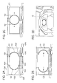
Fig. 2A illustrates the structure of thedisplay unit 10. - As illustrated in
Fig. 2A , themovement mechanism 103 of thedisplay unit 10 includes aguide rail 1041 laid laterally above thedisplay 101 and movement units provided so as to correspond to the respective twoframe elements 102. - Each movement unit provided for the
corresponding frame element 102 is constituted by ascrew 1042, amovement stage 1043 engaged with thescrew 1042 in a nut-like manner, and anactuator 1044 that drives thescrew 1042 to rotate it, which are arranged below thedisplay 101. Theactuator 1044 rotates thescrew 1042, so that themovement stage 1043 moves horizontally. - The
actuator 1044 is configured by using, for example, a servomotor or a stepping motor. - A transparent
top coupling member 1021 is fixed to the top of eachframe element 102, and a transparentbottom coupling member 1022 is fixed to the bottom of theframe element 102. Thebottom coupling member 1022 fixed to theframe element 102 is coupled to themovement stage 1043 of the movement unit corresponding to thisframe element 102, and thetop coupling member 1021 is slidably installed on theguide rail 1041. Thus, as illustrated inFigs. 2B and 2C , theframe elements 102 are arranged on a display surface of thedisplay 101 in such a manner as to be able to be moved in a horizontal direction by the movement units. - As illustrated in
Figs. 2A to 2D , the twoframe elements 102 are semicircular ring-shaped members. Theleft frame element 102 has a shape of the left half of a circular ring, and theright frame element 102 has a shape of the right half of the circular ring. As illustrated inFig. 2C , both theframe elements 102 are brought into contact with each other, thereby forming one circular ring-shaped meter ring. - As illustrated in
Fig. 2D , thisdisplay unit 10 is installed in an instrument panel below a meter cluster of the vehicle such that themovement mechanism 103 is concealed. - Referring back to
Fig. 1 , a display mode table and frame interpolation part data are stored in thestorage device 14 in advance. - The vehicle-mounted system has a plurality of display modes. As illustrated in
Fig. 3A , in the display mode table, pieces of display object information and frame element positions which correspond to the respective display modes are registered. - In display object information items, for each of display objects, which are graphical objects to be displayed on the
display 101 when a corresponding display mode is set, there are registered an object name, which is an identifier of the display object, a size in which the display object is to be displayed, a position at which the display object is to be displayed, and display attributes of the display object, such as transparency and a color scheme. - In the display object information items of the display mode table, a graphical object output by each
functional system 15 and a frame interpolation part image, which will be described below, may be registered as display objects. - In frame element position items, positions at which the left and
right frame elements 102 are respectively arranged when a corresponding display mode is set are registered. - As illustrated in
Fig. 3B , in the frame interpolation part data, frame interpolation part records provided for a plurality of frame interpolation part images that have been prepared in advance are registered. In each frame interpolation part record, an object name of a corresponding frame interpolation part image and the corresponding frame interpolation part image are registered. Here, the frame interpolation part image is a graphical object that specifies an image which couples theframe elements 102, which will be described in detail later. - Next, in such a configuration, a display control process performed by the
control device 12 will be described. -
Fig. 4 illustrates steps of the display control process. - As illustrated in
Fig. 4 , thecontrol device 12 monitors a change in display mode (step 402). Thecontrol device 12 changes a display mode in response to a display mode switching operation performed by a user via theinput device 13 or a change in the state of the vehicle monitored by the monitoring system. - When a change in display mode has occurred, an object name, a position, a size, and display attributes of each display object registered in the display object information items in a current display mode of the display mode table are acquired (step 404).
- The
movement mechanism 103 is controlled so as to move the left andright frame elements 102 to positions registered in the frame element position items in the current display mode of the display mode table (step 406). - Subsequently, display control is started on the basis of the acquired size, position, and display attributes of each display object whose object name has been acquired in step 404 (step 408).
- Then, the process returns to the monitoring process of
step 402. - In accordance with the above-described configuration and operations, examples of displays implemented in the embodiment will be described below.
-
Figs. 5A-1 to 5A-3 illustrate displays provided when a "back camera addition mode" is set as a display mode. - As illustrated in
Fig. 5A-1 , in the "back camera addition mode", a circular fuel gauge-equippedspeedometer image 501 that represents a speed and a fuel level of the vehicle, which is one of graphical objects output by the monitoring system, and aback camera image 502, which is one of graphical objects output by the back camera system, are set as display objects. As illustrated inFig. 5A-2 , an image in which these display objects are arranged is displayed on thedisplay 101. That is, pieces of display object information in the "back camera addition mode" of the display mode table are registered such that the image illustrated inFig. 5A-2 is defined. - In addition, in the "back camera addition mode", as illustrated in
Fig. 5A-3 , the left andright frame elements 102 are positioned at positions at which they are coupled so as to surround the fuel gauge-equippedspeedometer image 501, thereby forming one circular ring-shaped meter ring. That is, frame element positions in the "back camera addition mode" of the display mode table are registered such that the left andright frame elements 102 are positioned at the positions illustrated inFig. 5A-3 . - Next,
Figs. 5B-1 to 5B-3 illustrate displays provided when a "navigation + player addition mode" is set as a display mode. - As illustrated in
Fig. 5B-1 , in the "navigation + player addition mode", a music-being-playedinformation screen 511, which is one of graphical objects output by the AV system, a circular fuel gauge-equippedspeedometer image 512, which is one of graphical objects output by the monitoring system, and anavigation screen 513, which is one of graphical objects output by the navigation system, are set as display objects. As illustrated inFig. 5B-2 , an image in which these display objects are arranged is displayed on thedisplay 101. That is, pieces of display object information in the "navigation + player addition mode" of the display mode table are registered such that the image illustrated inFig. 5B-2 is defined. - In addition, in the "navigation + player addition mode", as illustrated in
Fig. 5B-3 , the left andright frame elements 102 are positioned at positions at which they are coupled so as to surround the fuel gauge-equippedspeedometer image 512, thereby forming one circular ring-shaped meter ring. That is, frame element positions in the "navigation + player addition mode" of the display mode table are registered such that the left andright frame elements 102 are positioned at the positions illustrated inFig. 5B-3 . - Next,
Figs. 6A-1 to 6A-3 illustrate displays provided when a "normal mode" is set as a display mode. - As illustrated in
Fig. 6A-1 , in the "normal mode", afuel gauge image 601, acircular speedometer image 602, acircular tachometer image 603, and athermometer image 604, all of which are graphical objects output by the monitoring system, and two frameinterpolation part images 605 are set as display objects. As illustrated inFig. 6A-2 , an image in which thefuel gauge image 601, thespeedometer image 602, thetachometer image 603, and thethermometer image 604 are arranged in this order from the left and in which the two frameinterpolation part images 605 are respectively arranged in upper and lower centers of a screen in the horizontal direction is displayed on thedisplay 101. That is, pieces of display object information in the "normal mode" of the display mode table are registered such that the image illustrated inFig. 6A-2 is defined. - In addition, in the "normal mode", as illustrated in
Fig. 6A-3 , the left andright frame elements 102 are horizontally positioned away from each other such that theleft frame element 102 surrounds the left side of thespeedometer image 602 and theright frame element 102 surrounds the right side of thetachometer image 603. That is, frame element positions in the "normal mode" of the display mode table are registered such that the left andright frame elements 102 are positioned at the positions illustrated inFig. 6A-3 . - Now, in the arrangement illustrated in
Fig. 6A-3 in which the left andright frame elements 102 are horizontally positioned away from each other, the two frameinterpolation part images 605 used in the "normal mode" are arranged and displayed on thedisplay 101 in a form that the two frameinterpolation part images 605 couple upper edges of the left andright frame elements 102 to each other and couple lower edges of them to each other, respectively. - Consequently, as illustrated in
Fig. 6A-3 , the left andright frame elements 102 and the upper and lower frameinterpolation part images 605 surround both thespeedometer image 602 and thetachometer image 603, thereby naturally representing one rounded rectangular meter ring (constituted by two parallel lines of equal length and two semicircular lines) without causing the user to feel strangeness. - As each frame
interpolation part image 605, an image which gradually gets darker towards the center thereof in the horizontal direction is used. This may produce stereoscopic visual effects with which the rounded rectangular meter ring seems to the user to extend out towards the left and right sides and the front. - Next,
Figs. 6B-1 to 6B-3 illustrate displays provided when a "navigation addition mode" is set as a display mode. - As illustrated in
Fig. 6B-1 , in the "navigation addition mode", a circular fuel gauge-equippedspeedometer image 611, which is a graphical object output by the monitoring system, anavigation screen 612, which is a graphical object output by the navigation system, a circular thermometer-equippedtachometer image 613, which is a graphical object output by the monitoring system, and two frameinterpolation part images 614 are set as display objects. As illustrated inFig. 6B-2 , an image in which the fuel gauge-equippedspeedometer image 611, thenavigation screen 612, and the thermometer-equippedtachometer image 613 are arranged in this order from the left and in which the two frameinterpolation part images 614 are respectively arranged in upper and lower centers of a screen in the horizontal direction is displayed on thedisplay 101. That is, pieces of display object information in the "navigation addition mode" of the display mode table are registered such that the image illustrated inFig. 6B-2 is defined. - In addition, in the "navigation addition mode", as illustrated in
Fig. 6B-3 , the left andright frame elements 102 are horizontally positioned away from each other such that theleft frame element 102 surrounds the left side of the fuel gauge-equippedspeedometer image 611 and theright frame element 102 surrounds the right side of the thermometer-equippedtachometer image 613. That is, frame element positions in the "navigation addition mode" of the display mode table are registered such that the left andright frame elements 102 are positioned at the positions illustrated inFig. 6B-3 . - Furthermore, in the arrangement illustrated in
Fig. 6B-3 in which the left andright frame elements 102 are horizontally positioned away from each other, the two frameinterpolation part images 614 used in the "navigation addition mode" are arranged and displayed on thedisplay 101 in a form that the two frameinterpolation part images 614 couple upper edges of the left andright frame elements 102 to each other and couple lower edges of them to each other, respectively. - Consequently, as illustrated in
Fig. 6B-3 , the left andright frame elements 102 and the upper and lower frameinterpolation part images 614 surround all of the fuel gauge-equippedspeedometer image 611, thenavigation screen 612, and the thermometer-equippedtachometer image 613, thereby naturally representing one rounded rectangular meter ring (constituted by two parallel lines of equal length and two semicircular lines) without causing the user to feel strangeness. - Here also, as each frame
interpolation part image 614, an image which gradually gets darker towards the center thereof in the horizontal direction is used. This may produce stereoscopic visual effects with which the rounded rectangular meter ring seems to the user to extend out towards the left and right sides and the front. - Now, in the case where frame interpolation part images are displayed as illustrated in
Figs. 6A-1 to 6A-3 and 6B-1 to 6B-3 ,other information 650 may also be displayed on a lower frame interpolation part image as illustrated inFig. 6B-3 . In the illustrated example, as theinformation 650, the title of music being played, which is output by the AV system, is displayed. In this way, information is displayed on the frameinterpolation part image 614, and thus a display including the information that exhibits a sense of unity may be produced. - The embodiment of the present invention has been described hereinabove.
- In the embodiment, the brightness of an image generated by arranging display objects as described above is reduced, through image processing or control of driving of the
display 101, towards a lower side at a reduction rate that becomes higher towards the lower side, and then the image is displayed on thedisplay 101. Thus, a meter image may be displayed by using visual effects with which an upper portion of a meter seems to extend out towards the front with respect to a lower portion of the meter. - In the embodiment, display switching performed when a display mode is switched may be performed while applying an appropriate transition effect to the display control process.
- That is, for example, the
control device 12 may control displays provided by thedisplay 101 and movement of theright frame element 102 such that, when switching from the "back camera addition mode" illustrated inFigs. 5A-1 to 5A-3 to the "navigation addition mode" illustrated inFigs. 6B-1 to 6B-3 is performed, as illustrated inFig. 7 , the circular ring-shaped meter ring illustrated inFig. 5A-3 expands in a right direction while pushing theback camera image 502 in the right direction until the rounded rectangular meter ring illustrated inFig. 6B-3 is formed, and also, with the expansion, the thermometer-equippedtachometer image 613 and thenavigation screen 612 are drawn from behind the fuel gauge-equippedspeedometer image 501 in the right direction. - In the embodiment, the semicircular ring-shaped left and
right frame elements 102 are used; alternatively, as illustrated inFigs. 8A-1 and 8A-2 , aleft frame element 801 having a shape of the left half of a quadrilateral frame and aright frame element 802 having a shape of the right half of the quadrilateral frame may be used in place of the left andright frame elements 102. - In the embodiment, the left and
right frame elements 102 are provided in such a manner as to be movable in the horizontal direction; alternatively, as illustrated inFigs. 8B-1 and 8B-2 , theframe elements 102 may be arranged on upper and lower sides and vertically moved. In this case, as illustrated inFigs. 8B-1 and 8B-2 , a plurality of sets of the upper andlower frame elements 102 may be provided. In the case where theframe elements 102 are arranged on the upper and lower sides, frame interpolation part images vertically couple left edges of the upper andlower frame elements 102 to each other and vertically couple right edges of them to each other, respectively. - In the embodiment, the two semicircular ring-shaped left and
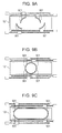
right frame elements 102 are used; alternatively, as illustrated inFig. 9A , four quarter-circular ring-shapedframe elements 901 on upper, lower, left, and right sides corresponding to the upper left quarter, lower left quarter, lower right quarter, and upper right quarter of a ring may be used in place of the two semicircular ring-shaped left andright frame elements 102. - In this case, note that the four quarter-circular ring-shaped
frame elements 901 are each provided with the above-described movement unit so that eachframe element 901 is independently movable in a horizontal direction. - Thus, even in the case where the four quarter-circular ring-shaped
frame elements 901 are used, as in the case where the two semicircular ring-shaped left andright frame elements 102 are used, one circular ring-shaped meter ring may be formed by coupling theframe elements 901 together as illustrated inFig. 9B , or one rounded rectangular meter ring whose two left and right semicircular portions are formed of theframe elements 901 and whose two upper and lower straight-line portions are formed of frame interpolation part images may be represented as illustrated inFig. 9C . - In addition, the four quarter-circular ring-shaped
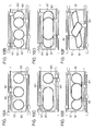
frame elements 901 are used together with displays of appropriate frame interpolation part images, thereby enabling three circular meter rings illustrated inFig. 10A , four circular meter rings illustrated inFig. 10B , one rounded rectangular meter ring and one circular meter ring illustrated inFig. 10C , or two rounded rectangular meter rings arranged in a nested manner illustrated inFig. 10D to be represented. - Furthermore, the four quarter-circular ring-shaped
frame elements 901 are used together with displays of appropriate frame interpolation part images, thereby enabling meter rings illustrated inFig. 10E , whose shapes are hard to form with actual meter rings, or irregularly-shaped frames illustrated inFig. 10F to be represented. - As described above, according to the embodiment, movement of frame elements and display of frame interpolation part images enable a certain size and shape of a frame to be set. Thus, an indicator surrounded by a frame, such as a meter equipped with a meter ring, may be represented in many different shapes and sizes in a natural form exhibiting a sense of unity.
Claims (10)
- A vehicle-mounted display system that displays an information presentation image representing information to be presented to a user, the vehicle-mounted display system comprising:a display (101);a plurality of frame elements (102) that are arranged on a display surface of the display (101) and respectively have shapes corresponding to different portions constituting one frame;a movement mechanism (103) that moves the frame elements (102) along the display surface of the display (101); andcontrol means (12) that controls positions of the frame elements (102) via the movement mechanism (103) and also controls a plurality of display modes in the display (101),wherein, when a first display mode among the plurality of display modes is set, the control means (12) controls the positions of the plurality of frame elements (102) such that the plurality of frame elements (102) are positioned away from each other, displays, on the display (101), frame interpolation part images representing frame portions that couple edges of the plurality of frame elements (102) such that one frame is formed of the plurality of frame elements (102) and the frame interpolation part images, and also displays the information presentation image inside the frame formed of the plurality of frame elements (102) and the frame interpolation part images.
- The vehicle-mounted display system according to Claim 1,
wherein the plurality of frame elements (102) are capable of moving to a position at which the edges of the plurality of frame elements (102) are brought into contact with each other, and, when the plurality of frame elements (102) are positioned at the position at which the edges of the plurality of frame elements (102) are brought into contact with each other, one frame is formed of only the plurality of frame elements (102), and
wherein, when a second display mode among the plurality of display modes is set, the control means (12) controls the positions of the plurality of frame elements (102) such that the plurality of frame elements (102) are positioned at the position at which the edges of the plurality of frame elements (102) are brought into contact with each other, and displays the information presentation image inside the frame formed of only the plurality of frame elements (102) without displaying the frame interpolation part images. - The vehicle-mounted display system according to Claim 1 or 2,
wherein, as the plurality of frame elements, there are provided an upper left frame element (901) that has a shape of an upper left quarter of a frame, a lower left frame element (901) that is arranged at a position which is vertically lower than a position of the upper left frame element (901) and that has a shape of a lower left quarter of the frame, an upper right frame element (901) that is arranged at a position which vertically coincides with the position of the upper left frame element (901) and is horizontally more to right than the position of the upper left frame element (901) and that has a shape of an upper right quarter of the frame, and a lower right frame element (901) that is arranged at a position which vertically coincides with a position of the lower left frame element (901) and is horizontally more to right than the position of the lower left frame element (901) and that has a shape of a lower right quarter of the frame. - The vehicle-mounted display system according to any of Claims 1-3,
wherein, as the plurality of frame elements, there are provided a left frame element (102) that has a shape of a left half of a frame and a right frame element (102) that is arranged on a right side of the left frame element (102) and has a shape of a right half of the frame,
wherein the movement mechanism (103) moves the left frame element (102) and the right frame element (102) in a horizontal direction, and
wherein, when the first display mode is set, the control means (12) controls positions of the left frame element (102) and the right frame element (102) such that the left frame element (102) and the right frame element (102) are horizontally positioned away from each other, and displays, on the display (101), as the frame interpolation part images, a frame upper interpolation part image that horizontally couples upper edges of the left frame element (102) and the right frame element (102) to each other and a frame lower interpolation part image that horizontally couples lower edges of the left frame element (102) and the right frame element (102) to each other such that one frame is formed of the left frame element (102), the right frame element (102), the frame upper interpolation part image, and the frame lower interpolation part image. - The vehicle-mounted display system according to Claim 4,
wherein the frame upper interpolation part image and the frame lower interpolation part image are each an image whose brightness gradually reduces from edges towards a center of the image in the horizontal direction. - The vehicle-mounted display system according to Claim 4 or 5,
wherein the control means (12) reduces brightness of the information presentation image towards a lower side at a reduction rate that becomes higher towards the lower side, and displays the information presentation image on the display (101). - The vehicle-mounted display system according to one of Claims 4-6,
wherein the left frame element (102) has a shape of a left half of a circular ring-shaped meter ring and the right frame element (102) has a shape of a right half of the circular ring-shaped meter ring, and
wherein, when the first display mode is set, the control means (12) displays, on the display (101), the frame upper interpolation part image and the frame lower interpolation part image such that one rounded rectangular frame is formed of the left frame element (102), the right frame element (102), the frame upper interpolation part image, and the frame lower interpolation part image. - The vehicle-mounted display system according to Claim 7,
wherein, when the first display mode is set, the control means (12) displays, as the information presentation image, a first meter image representing a circular meter that is arranged such that a left half of the circular meter is surrounded by the left frame element (102) and a second meter image representing a circular meter that is arranged such that a right half of the circular meter is surrounded by the right frame element (102). - The vehicle-mounted display system according to Claim 8,
wherein the left frame element (102) and the right frame element (102) are capable of moving to a position at which upper edges of the left frame element (102) and the right frame element (102) are brought into contact with each other and at which lower edges of the left frame element (102) and the right frame element (102) are brought into contact with each other, and, when the left frame element (102) and the right frame element (102) are positioned at the position at which the upper edges are brought into contact with each other and at which the lower edges are brought into contact with each other, one circular ring-shaped frame is formed of only the left frame element (102) and the right frame element (102), and
wherein, when a second display mode among the plurality of display modes is set, the control means (12) displays, as the information presentation image, a third meter image representing a circular meter that is arranged so as to be surrounded by the circular ring-shaped frame formed of the left frame element (102) and the right frame element (102) without displaying the frame upper interpolation part image and the frame lower interpolation part image. - The vehicle-mounted display system according to one of Claims 4-9,
wherein the left frame element (102) and the right frame element (102) are capable of moving to a position at which upper edges of the left frame element (102) and the right frame element (102) are brought into contact with each other and at which lower edges of the left frame element (102) and the right frame element (102) are brought into contact with each other, and, when the left frame element (102) and the right frame element (102) are positioned at the position at which the upper edges are brought into contact with each other and at which the lower edges are brought into contact with each other, one circular ring-shaped frame is formed of only the left frame element (102) and the right frame element (102), and
wherein, when a second display mode among the plurality of display modes is set, the control means (12) controls positions of the left frame element (102) and the right frame element (102) such that the left frame element (102) and the right frame element (102) are positioned at the position at which the upper edges are brought into contact with each other and at which the lower edges are brought into contact with each other, and displays, as the information presentation image, a meter image representing a circular meter that is arranged so as to be surrounded by the circular ring-shaped frame formed of the left frame element (102) and the right frame element (102) without displaying the frame upper interpolation part image and the frame lower interpolation part image.
Applications Claiming Priority (1)
| Application Number | Priority Date | Filing Date | Title |
|---|---|---|---|
| JP2013076683A JP6177565B2 (en) | 2013-04-02 | 2013-04-02 | In-vehicle display system |
Publications (3)
| Publication Number | Publication Date |
|---|---|
| EP2786887A2 true EP2786887A2 (en) | 2014-10-08 |
| EP2786887A3 EP2786887A3 (en) | 2015-08-19 |
| EP2786887B1 EP2786887B1 (en) | 2020-04-29 |
Family
ID=50624371
Family Applications (1)
| Application Number | Title | Priority Date | Filing Date |
|---|---|---|---|
| EP14161749.8A Not-in-force EP2786887B1 (en) | 2013-04-02 | 2014-03-26 | Vehicle-mounted display system |
Country Status (4)
| Country | Link |
|---|---|
| US (1) | US9139127B2 (en) |
| EP (1) | EP2786887B1 (en) |
| JP (1) | JP6177565B2 (en) |
| CN (1) | CN104097515B (en) |
Families Citing this family (10)
| Publication number | Priority date | Publication date | Assignee | Title |
|---|---|---|---|---|
| JP6080681B2 (en) * | 2012-09-04 | 2017-02-15 | アルパイン株式会社 | In-vehicle display device |
| JP6160474B2 (en) * | 2013-12-24 | 2017-07-12 | 株式会社デンソー | Display device |
| JP6260583B2 (en) * | 2015-06-16 | 2018-01-17 | 株式会社デンソー | Display device |
| JP6429035B2 (en) * | 2016-04-19 | 2018-11-28 | トヨタ自動車株式会社 | Vehicle display device |
| KR20180032109A (en) | 2016-09-21 | 2018-03-29 | 엘지전자 주식회사 | Dashboard display and vehicle comprising the same |
| TW201838829A (en) * | 2017-02-06 | 2018-11-01 | 愛爾蘭商滿捷特科技公司 | Inkjet print head for full color page wide printing |
| DE102018219481A1 (en) * | 2018-11-15 | 2020-05-20 | Robert Bosch Gmbh | Assembly for a LiDAR sensor and LiDAR sensor |
| US11703590B2 (en) * | 2018-11-19 | 2023-07-18 | Suteng Innovation Technology Co., Ltd. | Lidar signal receiving circuits, lidar signal gain control methods, and lidars using the same |
| JP6978469B2 (en) * | 2019-05-21 | 2021-12-08 | 矢崎総業株式会社 | Display unit |
| CN113538624B (en) * | 2021-07-23 | 2024-06-11 | 腾讯云计算(北京)有限责任公司 | A method, device, equipment and medium for drawing rounded corners of fan-shaped page elements |
Citations (2)
| Publication number | Priority date | Publication date | Assignee | Title |
|---|---|---|---|---|
| JP4648681B2 (en) | 2004-11-02 | 2011-03-09 | 矢崎総業株式会社 | Vehicle display device |
| JP2012032209A (en) | 2010-07-29 | 2012-02-16 | Denso Corp | Meter unit for vehicle |
Family Cites Families (9)
| Publication number | Priority date | Publication date | Assignee | Title |
|---|---|---|---|---|
| JP4067654B2 (en) * | 1998-06-22 | 2008-03-26 | カルソニックカンセイ株式会社 | Dial plate making apparatus and method |
| JP2002012056A (en) * | 2000-06-29 | 2002-01-15 | Calsonic Kansei Corp | Instrument for vehicle |
| DE102005003920B4 (en) * | 2004-01-28 | 2017-01-26 | Yazaki Corporation | display unit |
| DE102005042695B4 (en) * | 2004-12-30 | 2018-01-25 | Volkswagen Ag | Motor vehicle with a display device |
| US8577487B2 (en) * | 2010-02-23 | 2013-11-05 | Paccar Inc | Customized instrument evaluation and ordering tool |
| JP5538069B2 (en) * | 2010-05-28 | 2014-07-02 | 矢崎総業株式会社 | Vehicle display device |
| JP5455828B2 (en) * | 2010-07-23 | 2014-03-26 | 矢崎総業株式会社 | Instrument graphic display apparatus and method |
| JP2012244600A (en) * | 2011-05-24 | 2012-12-10 | Fujitsu Ten Ltd | Image display system, image processing apparatus, and image display method |
| JP5720494B2 (en) * | 2011-08-23 | 2015-05-20 | 日本精機株式会社 | Display device |
-
2013
- 2013-04-02 JP JP2013076683A patent/JP6177565B2/en active Active
-
2014
- 2014-02-05 US US14/173,386 patent/US9139127B2/en not_active Expired - Fee Related
- 2014-03-11 CN CN201410086799.0A patent/CN104097515B/en not_active Expired - Fee Related
- 2014-03-26 EP EP14161749.8A patent/EP2786887B1/en not_active Not-in-force
Patent Citations (2)
| Publication number | Priority date | Publication date | Assignee | Title |
|---|---|---|---|---|
| JP4648681B2 (en) | 2004-11-02 | 2011-03-09 | 矢崎総業株式会社 | Vehicle display device |
| JP2012032209A (en) | 2010-07-29 | 2012-02-16 | Denso Corp | Meter unit for vehicle |
Also Published As
| Publication number | Publication date |
|---|---|
| CN104097515A (en) | 2014-10-15 |
| CN104097515B (en) | 2018-02-13 |
| US20140292828A1 (en) | 2014-10-02 |
| JP2014202516A (en) | 2014-10-27 |
| EP2786887A3 (en) | 2015-08-19 |
| JP6177565B2 (en) | 2017-08-09 |
| EP2786887B1 (en) | 2020-04-29 |
| US9139127B2 (en) | 2015-09-22 |
Similar Documents
| Publication | Publication Date | Title |
|---|---|---|
| EP2786887B1 (en) | Vehicle-mounted display system | |
| KR100823272B1 (en) | Computer-readable recording medium recording method and apparatus for displaying three-dimensional menu and program for performing the method | |
| CN110506231A (en) | Method and system for object ripples in display systems including multiple displays | |
| US9619926B2 (en) | Method and device for generating a 3D representation of a user interface in a vehicle | |
| CA2811491C (en) | Method for three-dimensional viewing | |
| EP2926555A1 (en) | Low latency image display on multi-display device | |
| EP4339688A1 (en) | Efficiency enhancements to construction of virtual reality environments | |
| JP6121131B2 (en) | Multiple display device | |
| RU2009135574A (en) | METHOD AND SYSTEM OF PROVIDING CONTENT | |
| JP6359113B2 (en) | Display control system and display control method | |
| CN101034208A (en) | Three-dimensional simulation sand table system | |
| WO2023086091A1 (en) | Methods and systems for presenting media content with multiple media elements in an editing environment | |
| JP2013105183A5 (en) | ||
| JP2005149175A (en) | Display control apparatus and program | |
| JP2001331245A (en) | Stereoscopic image display device and information storage medium | |
| JP6260352B2 (en) | Vehicle display device | |
| JP2015042941A (en) | Multi-display control apparatus and multi-display control method | |
| JP2013130928A (en) | Design support device, and method and program for design support | |
| JP2013221848A (en) | Display device for vehicle | |
| JP4711001B2 (en) | Vehicle instrument and method of displaying vehicle state value | |
| JP2007250048A5 (en) | ||
| CN103210423A (en) | Stereo image processing device and related method | |
| JP6184230B2 (en) | Display system | |
| JP2009295182A (en) | Storage medium and image generation apparatus | |
| JP2015205550A (en) | Vehicular display device |
Legal Events
| Date | Code | Title | Description |
|---|---|---|---|
| PUAI | Public reference made under article 153(3) epc to a published international application that has entered the european phase |
Free format text: ORIGINAL CODE: 0009012 |
|
| 17P | Request for examination filed |
Effective date: 20140326 |
|
| AK | Designated contracting states |
Kind code of ref document: A2 Designated state(s): AL AT BE BG CH CY CZ DE DK EE ES FI FR GB GR HR HU IE IS IT LI LT LU LV MC MK MT NL NO PL PT RO RS SE SI SK SM TR |
|
| AX | Request for extension of the european patent |
Extension state: BA ME |
|
| PUAL | Search report despatched |
Free format text: ORIGINAL CODE: 0009013 |
|
| AK | Designated contracting states |
Kind code of ref document: A3 Designated state(s): AL AT BE BG CH CY CZ DE DK EE ES FI FR GB GR HR HU IE IS IT LI LT LU LV MC MK MT NL NO PL PT RO RS SE SI SK SM TR |
|
| AX | Request for extension of the european patent |
Extension state: BA ME |
|
| RIC1 | Information provided on ipc code assigned before grant |
Ipc: B60K 37/02 20060101ALI20150714BHEP Ipc: B60K 35/00 20060101AFI20150714BHEP |
|
| R17P | Request for examination filed (corrected) |
Effective date: 20160128 |
|
| RBV | Designated contracting states (corrected) |
Designated state(s): AL AT BE BG CH CY CZ DE DK EE ES FI FR GB GR HR HU IE IS IT LI LT LU LV MC MK MT NL NO PL PT RO RS SE SI SK SM TR |
|
| RIC1 | Information provided on ipc code assigned before grant |
Ipc: B60K 37/02 20060101ALI20190822BHEP Ipc: B60K 35/00 20060101AFI20190822BHEP |
|
| GRAP | Despatch of communication of intention to grant a patent |
Free format text: ORIGINAL CODE: EPIDOSNIGR1 |
|
| STAA | Information on the status of an ep patent application or granted ep patent |
Free format text: STATUS: GRANT OF PATENT IS INTENDED |
|
| INTG | Intention to grant announced |
Effective date: 20191017 |
|
| GRAS | Grant fee paid |
Free format text: ORIGINAL CODE: EPIDOSNIGR3 |
|
| GRAA | (expected) grant |
Free format text: ORIGINAL CODE: 0009210 |
|
| STAA | Information on the status of an ep patent application or granted ep patent |
Free format text: STATUS: THE PATENT HAS BEEN GRANTED |
|
| AK | Designated contracting states |
Kind code of ref document: B1 Designated state(s): AL AT BE BG CH CY CZ DE DK EE ES FI FR GB GR HR HU IE IS IT LI LT LU LV MC MK MT NL NO PL PT RO RS SE SI SK SM TR |
|
| REG | Reference to a national code |
Ref country code: GB Ref legal event code: FG4D |
|
| REG | Reference to a national code |
Ref country code: CH Ref legal event code: EP |
|
| REG | Reference to a national code |
Ref country code: DE Ref legal event code: R096 Ref document number: 602014064405 Country of ref document: DE |
|
| REG | Reference to a national code |
Ref country code: AT Ref legal event code: REF Ref document number: 1262797 Country of ref document: AT Kind code of ref document: T Effective date: 20200515 |
|
| REG | Reference to a national code |
Ref country code: IE Ref legal event code: FG4D |
|
| REG | Reference to a national code |
Ref country code: NL Ref legal event code: MP Effective date: 20200429 |
|
| REG | Reference to a national code |
Ref country code: LT Ref legal event code: MG4D |
|
| PG25 | Lapsed in a contracting state [announced via postgrant information from national office to epo] |
Ref country code: LT Free format text: LAPSE BECAUSE OF FAILURE TO SUBMIT A TRANSLATION OF THE DESCRIPTION OR TO PAY THE FEE WITHIN THE PRESCRIBED TIME-LIMIT Effective date: 20200429 Ref country code: GR Free format text: LAPSE BECAUSE OF FAILURE TO SUBMIT A TRANSLATION OF THE DESCRIPTION OR TO PAY THE FEE WITHIN THE PRESCRIBED TIME-LIMIT Effective date: 20200730 Ref country code: IS Free format text: LAPSE BECAUSE OF FAILURE TO SUBMIT A TRANSLATION OF THE DESCRIPTION OR TO PAY THE FEE WITHIN THE PRESCRIBED TIME-LIMIT Effective date: 20200829 Ref country code: SE Free format text: LAPSE BECAUSE OF FAILURE TO SUBMIT A TRANSLATION OF THE DESCRIPTION OR TO PAY THE FEE WITHIN THE PRESCRIBED TIME-LIMIT Effective date: 20200429 Ref country code: PT Free format text: LAPSE BECAUSE OF FAILURE TO SUBMIT A TRANSLATION OF THE DESCRIPTION OR TO PAY THE FEE WITHIN THE PRESCRIBED TIME-LIMIT Effective date: 20200831 Ref country code: NO Free format text: LAPSE BECAUSE OF FAILURE TO SUBMIT A TRANSLATION OF THE DESCRIPTION OR TO PAY THE FEE WITHIN THE PRESCRIBED TIME-LIMIT Effective date: 20200729 Ref country code: FI Free format text: LAPSE BECAUSE OF FAILURE TO SUBMIT A TRANSLATION OF THE DESCRIPTION OR TO PAY THE FEE WITHIN THE PRESCRIBED TIME-LIMIT Effective date: 20200429 |
|
| REG | Reference to a national code |
Ref country code: AT Ref legal event code: MK05 Ref document number: 1262797 Country of ref document: AT Kind code of ref document: T Effective date: 20200429 |
|
| PG25 | Lapsed in a contracting state [announced via postgrant information from national office to epo] |
Ref country code: RS Free format text: LAPSE BECAUSE OF FAILURE TO SUBMIT A TRANSLATION OF THE DESCRIPTION OR TO PAY THE FEE WITHIN THE PRESCRIBED TIME-LIMIT Effective date: 20200429 Ref country code: LV Free format text: LAPSE BECAUSE OF FAILURE TO SUBMIT A TRANSLATION OF THE DESCRIPTION OR TO PAY THE FEE WITHIN THE PRESCRIBED TIME-LIMIT Effective date: 20200429 Ref country code: HR Free format text: LAPSE BECAUSE OF FAILURE TO SUBMIT A TRANSLATION OF THE DESCRIPTION OR TO PAY THE FEE WITHIN THE PRESCRIBED TIME-LIMIT Effective date: 20200429 Ref country code: BG Free format text: LAPSE BECAUSE OF FAILURE TO SUBMIT A TRANSLATION OF THE DESCRIPTION OR TO PAY THE FEE WITHIN THE PRESCRIBED TIME-LIMIT Effective date: 20200729 |
|
| PG25 | Lapsed in a contracting state [announced via postgrant information from national office to epo] |
Ref country code: AL Free format text: LAPSE BECAUSE OF FAILURE TO SUBMIT A TRANSLATION OF THE DESCRIPTION OR TO PAY THE FEE WITHIN THE PRESCRIBED TIME-LIMIT Effective date: 20200429 Ref country code: NL Free format text: LAPSE BECAUSE OF FAILURE TO SUBMIT A TRANSLATION OF THE DESCRIPTION OR TO PAY THE FEE WITHIN THE PRESCRIBED TIME-LIMIT Effective date: 20200429 |
|
| PG25 | Lapsed in a contracting state [announced via postgrant information from national office to epo] |
Ref country code: ES Free format text: LAPSE BECAUSE OF FAILURE TO SUBMIT A TRANSLATION OF THE DESCRIPTION OR TO PAY THE FEE WITHIN THE PRESCRIBED TIME-LIMIT Effective date: 20200429 Ref country code: CZ Free format text: LAPSE BECAUSE OF FAILURE TO SUBMIT A TRANSLATION OF THE DESCRIPTION OR TO PAY THE FEE WITHIN THE PRESCRIBED TIME-LIMIT Effective date: 20200429 Ref country code: SM Free format text: LAPSE BECAUSE OF FAILURE TO SUBMIT A TRANSLATION OF THE DESCRIPTION OR TO PAY THE FEE WITHIN THE PRESCRIBED TIME-LIMIT Effective date: 20200429 Ref country code: RO Free format text: LAPSE BECAUSE OF FAILURE TO SUBMIT A TRANSLATION OF THE DESCRIPTION OR TO PAY THE FEE WITHIN THE PRESCRIBED TIME-LIMIT Effective date: 20200429 Ref country code: IT Free format text: LAPSE BECAUSE OF FAILURE TO SUBMIT A TRANSLATION OF THE DESCRIPTION OR TO PAY THE FEE WITHIN THE PRESCRIBED TIME-LIMIT Effective date: 20200429 Ref country code: DK Free format text: LAPSE BECAUSE OF FAILURE TO SUBMIT A TRANSLATION OF THE DESCRIPTION OR TO PAY THE FEE WITHIN THE PRESCRIBED TIME-LIMIT Effective date: 20200429 Ref country code: EE Free format text: LAPSE BECAUSE OF FAILURE TO SUBMIT A TRANSLATION OF THE DESCRIPTION OR TO PAY THE FEE WITHIN THE PRESCRIBED TIME-LIMIT Effective date: 20200429 Ref country code: AT Free format text: LAPSE BECAUSE OF FAILURE TO SUBMIT A TRANSLATION OF THE DESCRIPTION OR TO PAY THE FEE WITHIN THE PRESCRIBED TIME-LIMIT Effective date: 20200429 |
|
| REG | Reference to a national code |
Ref country code: DE Ref legal event code: R097 Ref document number: 602014064405 Country of ref document: DE |
|
| PG25 | Lapsed in a contracting state [announced via postgrant information from national office to epo] |
Ref country code: SK Free format text: LAPSE BECAUSE OF FAILURE TO SUBMIT A TRANSLATION OF THE DESCRIPTION OR TO PAY THE FEE WITHIN THE PRESCRIBED TIME-LIMIT Effective date: 20200429 Ref country code: PL Free format text: LAPSE BECAUSE OF FAILURE TO SUBMIT A TRANSLATION OF THE DESCRIPTION OR TO PAY THE FEE WITHIN THE PRESCRIBED TIME-LIMIT Effective date: 20200429 |
|
| PLBE | No opposition filed within time limit |
Free format text: ORIGINAL CODE: 0009261 |
|
| STAA | Information on the status of an ep patent application or granted ep patent |
Free format text: STATUS: NO OPPOSITION FILED WITHIN TIME LIMIT |
|
| 26N | No opposition filed |
Effective date: 20210201 |
|
| PG25 | Lapsed in a contracting state [announced via postgrant information from national office to epo] |
Ref country code: SI Free format text: LAPSE BECAUSE OF FAILURE TO SUBMIT A TRANSLATION OF THE DESCRIPTION OR TO PAY THE FEE WITHIN THE PRESCRIBED TIME-LIMIT Effective date: 20200429 |
|
| PG25 | Lapsed in a contracting state [announced via postgrant information from national office to epo] |
Ref country code: MC Free format text: LAPSE BECAUSE OF FAILURE TO SUBMIT A TRANSLATION OF THE DESCRIPTION OR TO PAY THE FEE WITHIN THE PRESCRIBED TIME-LIMIT Effective date: 20200429 |
|
| REG | Reference to a national code |
Ref country code: CH Ref legal event code: PL |
|
| REG | Reference to a national code |
Ref country code: BE Ref legal event code: MM Effective date: 20210331 |
|
| PG25 | Lapsed in a contracting state [announced via postgrant information from national office to epo] |
Ref country code: CH Free format text: LAPSE BECAUSE OF NON-PAYMENT OF DUE FEES Effective date: 20210331 Ref country code: LU Free format text: LAPSE BECAUSE OF NON-PAYMENT OF DUE FEES Effective date: 20210326 Ref country code: LI Free format text: LAPSE BECAUSE OF NON-PAYMENT OF DUE FEES Effective date: 20210331 Ref country code: IE Free format text: LAPSE BECAUSE OF NON-PAYMENT OF DUE FEES Effective date: 20210326 |
|
| PG25 | Lapsed in a contracting state [announced via postgrant information from national office to epo] |
Ref country code: BE Free format text: LAPSE BECAUSE OF NON-PAYMENT OF DUE FEES Effective date: 20210331 |
|
| PGFP | Annual fee paid to national office [announced via postgrant information from national office to epo] |
Ref country code: FR Payment date: 20230324 Year of fee payment: 10 |
|
| PG25 | Lapsed in a contracting state [announced via postgrant information from national office to epo] |
Ref country code: HU Free format text: LAPSE BECAUSE OF FAILURE TO SUBMIT A TRANSLATION OF THE DESCRIPTION OR TO PAY THE FEE WITHIN THE PRESCRIBED TIME-LIMIT; INVALID AB INITIO Effective date: 20140326 |
|
| PGFP | Annual fee paid to national office [announced via postgrant information from national office to epo] |
Ref country code: GB Payment date: 20230322 Year of fee payment: 10 Ref country code: DE Payment date: 20220620 Year of fee payment: 10 |
|
| PG25 | Lapsed in a contracting state [announced via postgrant information from national office to epo] |
Ref country code: CY Free format text: LAPSE BECAUSE OF FAILURE TO SUBMIT A TRANSLATION OF THE DESCRIPTION OR TO PAY THE FEE WITHIN THE PRESCRIBED TIME-LIMIT Effective date: 20200429 |
|
| PG25 | Lapsed in a contracting state [announced via postgrant information from national office to epo] |
Ref country code: MK Free format text: LAPSE BECAUSE OF FAILURE TO SUBMIT A TRANSLATION OF THE DESCRIPTION OR TO PAY THE FEE WITHIN THE PRESCRIBED TIME-LIMIT Effective date: 20200429 |
|
| PG25 | Lapsed in a contracting state [announced via postgrant information from national office to epo] |
Ref country code: MT Free format text: LAPSE BECAUSE OF FAILURE TO SUBMIT A TRANSLATION OF THE DESCRIPTION OR TO PAY THE FEE WITHIN THE PRESCRIBED TIME-LIMIT Effective date: 20200429 |
|
| REG | Reference to a national code |
Ref country code: DE Ref legal event code: R119 Ref document number: 602014064405 Country of ref document: DE |
|
| GBPC | Gb: european patent ceased through non-payment of renewal fee |
Effective date: 20240326 |
|
| PG25 | Lapsed in a contracting state [announced via postgrant information from national office to epo] |
Ref country code: DE Free format text: LAPSE BECAUSE OF NON-PAYMENT OF DUE FEES Effective date: 20241001 |
|
| PG25 | Lapsed in a contracting state [announced via postgrant information from national office to epo] |
Ref country code: GB Free format text: LAPSE BECAUSE OF NON-PAYMENT OF DUE FEES Effective date: 20240326 |
|
| PG25 | Lapsed in a contracting state [announced via postgrant information from national office to epo] |
Ref country code: FR Free format text: LAPSE BECAUSE OF NON-PAYMENT OF DUE FEES Effective date: 20240331 |
|
| PG25 | Lapsed in a contracting state [announced via postgrant information from national office to epo] |
Ref country code: GB Free format text: LAPSE BECAUSE OF NON-PAYMENT OF DUE FEES Effective date: 20240326 Ref country code: FR Free format text: LAPSE BECAUSE OF NON-PAYMENT OF DUE FEES Effective date: 20240331 Ref country code: DE Free format text: LAPSE BECAUSE OF NON-PAYMENT OF DUE FEES Effective date: 20241001 |
|
| PG25 | Lapsed in a contracting state [announced via postgrant information from national office to epo] |
Ref country code: TR Free format text: LAPSE BECAUSE OF FAILURE TO SUBMIT A TRANSLATION OF THE DESCRIPTION OR TO PAY THE FEE WITHIN THE PRESCRIBED TIME-LIMIT Effective date: 20200429 |