EP2786871A2 - Ink circulation apparatus, ink circulation method and inkjet recording apparatus - Google Patents
Ink circulation apparatus, ink circulation method and inkjet recording apparatus Download PDFInfo
- Publication number
- EP2786871A2 EP2786871A2 EP14163368.5A EP14163368A EP2786871A2 EP 2786871 A2 EP2786871 A2 EP 2786871A2 EP 14163368 A EP14163368 A EP 14163368A EP 2786871 A2 EP2786871 A2 EP 2786871A2
- Authority
- EP
- European Patent Office
- Prior art keywords
- ink
- radical polymerization
- oxygen
- type
- mode
- Prior art date
- Legal status (The legal status is an assumption and is not a legal conclusion. Google has not performed a legal analysis and makes no representation as to the accuracy of the status listed.)
- Granted
Links
- 238000000034 method Methods 0.000 title claims description 56
- QVGXLLKOCUKJST-UHFFFAOYSA-N atomic oxygen Chemical compound [O] QVGXLLKOCUKJST-UHFFFAOYSA-N 0.000 claims abstract description 155
- 239000001301 oxygen Substances 0.000 claims abstract description 155
- 229910052760 oxygen Inorganic materials 0.000 claims abstract description 155
- 238000003848 UV Light-Curing Methods 0.000 claims abstract description 74
- 239000007789 gas Substances 0.000 claims abstract description 35
- 238000001723 curing Methods 0.000 claims description 43
- 239000012510 hollow fiber Substances 0.000 claims description 12
- 239000012528 membrane Substances 0.000 claims description 11
- 238000007599 discharging Methods 0.000 claims description 9
- 230000001678 irradiating effect Effects 0.000 claims description 2
- 239000002245 particle Substances 0.000 abstract description 8
- 239000002609 medium Substances 0.000 description 48
- 230000008569 process Effects 0.000 description 30
- 238000010586 diagram Methods 0.000 description 13
- 238000012545 processing Methods 0.000 description 9
- 230000003247 decreasing effect Effects 0.000 description 7
- 239000007788 liquid Substances 0.000 description 7
- 239000003086 colorant Substances 0.000 description 5
- 230000008719 thickening Effects 0.000 description 5
- 238000012546 transfer Methods 0.000 description 5
- 230000015572 biosynthetic process Effects 0.000 description 4
- 230000007246 mechanism Effects 0.000 description 4
- 238000006243 chemical reaction Methods 0.000 description 3
- 230000002950 deficient Effects 0.000 description 3
- 238000010438 heat treatment Methods 0.000 description 3
- 238000012423 maintenance Methods 0.000 description 3
- 239000000463 material Substances 0.000 description 3
- 239000011159 matrix material Substances 0.000 description 3
- 230000032258 transport Effects 0.000 description 3
- 238000009281 ultraviolet germicidal irradiation Methods 0.000 description 3
- 238000011144 upstream manufacturing Methods 0.000 description 3
- 238000004804 winding Methods 0.000 description 3
- 230000008859 change Effects 0.000 description 2
- 238000005520 cutting process Methods 0.000 description 2
- 230000007423 decrease Effects 0.000 description 2
- 238000002474 experimental method Methods 0.000 description 2
- 230000010349 pulsation Effects 0.000 description 2
- 239000004698 Polyethylene Substances 0.000 description 1
- BZHJMEDXRYGGRV-UHFFFAOYSA-N Vinyl chloride Chemical compound ClC=C BZHJMEDXRYGGRV-UHFFFAOYSA-N 0.000 description 1
- 238000009835 boiling Methods 0.000 description 1
- 238000004364 calculation method Methods 0.000 description 1
- 238000004140 cleaning Methods 0.000 description 1
- 238000004891 communication Methods 0.000 description 1
- 238000009792 diffusion process Methods 0.000 description 1
- 239000006185 dispersion Substances 0.000 description 1
- 239000002612 dispersion medium Substances 0.000 description 1
- 239000004744 fabric Substances 0.000 description 1
- 239000000835 fiber Substances 0.000 description 1
- 239000010419 fine particle Substances 0.000 description 1
- 239000003999 initiator Substances 0.000 description 1
- 238000004519 manufacturing process Methods 0.000 description 1
- 230000000704 physical effect Effects 0.000 description 1
- 229920000728 polyester Polymers 0.000 description 1
- -1 polyethylene Polymers 0.000 description 1
- 229920000573 polyethylene Polymers 0.000 description 1
- 230000000379 polymerizing effect Effects 0.000 description 1
- 238000013139 quantization Methods 0.000 description 1
- 238000010526 radical polymerization reaction Methods 0.000 description 1
- 230000000717 retained effect Effects 0.000 description 1
- 229920006395 saturated elastomer Polymers 0.000 description 1
- 239000002904 solvent Substances 0.000 description 1
- 230000006641 stabilisation Effects 0.000 description 1
- 238000011105 stabilization Methods 0.000 description 1
- 239000000126 substance Substances 0.000 description 1
Images





Classifications
-
- B—PERFORMING OPERATIONS; TRANSPORTING
- B41—PRINTING; LINING MACHINES; TYPEWRITERS; STAMPS
- B41J—TYPEWRITERS; SELECTIVE PRINTING MECHANISMS, i.e. MECHANISMS PRINTING OTHERWISE THAN FROM A FORME; CORRECTION OF TYPOGRAPHICAL ERRORS
- B41J2/00—Typewriters or selective printing mechanisms characterised by the printing or marking process for which they are designed
- B41J2/005—Typewriters or selective printing mechanisms characterised by the printing or marking process for which they are designed characterised by bringing liquid or particles selectively into contact with a printing material
- B41J2/01—Ink jet
- B41J2/17—Ink jet characterised by ink handling
- B41J2/175—Ink supply systems ; Circuit parts therefor
-
- B—PERFORMING OPERATIONS; TRANSPORTING
- B41—PRINTING; LINING MACHINES; TYPEWRITERS; STAMPS
- B41J—TYPEWRITERS; SELECTIVE PRINTING MECHANISMS, i.e. MECHANISMS PRINTING OTHERWISE THAN FROM A FORME; CORRECTION OF TYPOGRAPHICAL ERRORS
- B41J2202/00—Embodiments of or processes related to ink-jet or thermal heads
- B41J2202/01—Embodiments of or processes related to ink-jet heads
- B41J2202/12—Embodiments of or processes related to ink-jet heads with ink circulating through the whole print head
Definitions
- the present invention relates to an ink circulation apparatus, an ink circulation method, and an inkjet recording apparatus, and particularly to a technique of preventing a defected nozzle of the inkjet head from being generated.
- the inkjet recording apparatus if bubbles or dissolved gas exists in ink, the ink may not be sufficiently compressed when being ejected, so the ejection property is decreased, and the ink flow is not stable. Accordingly, dot omission or defective printing may occur.
- JP1993-17712 JP-H5-17712
- a technique of transmitting dissolved gas in ink through a layer having a transmitting property and removing the gas is disclosed. According to the technique, gas can be easily removed even from ink generating bubbles and ink having a volatile component.
- JP2006-110780 discloses an inkjet recording apparatus, that includes a gas removing unit that removes dissolved gas from ink supplied to an ink chamber and a gas supply unit that supplies gas to the ink supplied to the ink chamber.
- the gas removing unit is driven and controlled so that ink from which the dissolved gas is removed fills the ink chamber, and when the inkjet head does not perform the ejection operation, the gas removing unit is driven and controlled so that ink to which gas is supplied fills the ink chamber.
- the inkjet head performs the ejection operation, the ink from which the dissolved gas is removed fills the ink chamber, so bubbles caused by dissolved gas in the ink chamber can be suppressed from being generated.
- the ink to which gas is supplied and in which dissolved gas is increased fills the ink chamber, so the ink in the ink chamber is not easily cured, and particles caused by the cured ink can be suppressed from being generated.
- Ink is thickened when a solvent of ink evaporates at a nozzle.
- a technique of providing an ink circulating path in the vicinity of the nozzle and circulating the ink in the nozzle in order to prevent the ink from being thickened has been known.
- the technique of circulating the ink in this manner may not be applied to the technique of JP2006-110780 .
- an object of the invention is to provide an ink circulation apparatus, an ink circulation method, and an inkjet recording apparatus that can simultaneously prevent the generation of bubbles in ink, the thickening of ink, and the generation of particles when radical polymerization-type UV-curing ink is circulated in an inkjet head.
- an ink circulation apparatus including: an ink tank that accumulates radical polymerization-type UV-curing ink so as to be in contact with gas including at least oxygen; a supplying flow path that communicates with the ink tank and a supply port of an inkjet head including the supply port to which the radical polymerization-type UV-curing ink is supplied, a nozzle that ejects the radical polymerization-type UV-curing ink, and a discharge port from which the radical polymerization-type UV-curing ink that is not ejected from the nozzle is discharged; a supply pump that is provided in the supplying flow path, and supplies the radical polymerization-type UV-curing ink accumulated in the ink tank to the inkjet head; oxygen removing means that is provided in the supplying flow path, and removes oxygen from the radical polymerization-type UV-curing ink; a discharging flow path that communicates with the discharge port of the inkjet head and the
- oxygen is removed from radical polymerization-type UV-curing ink to be supplied to the inkjet head in the first mode, bubbles are prevented from being generated in the inkjet head so dot omission or defective printing may not occur.
- ink is circulated without removing oxygen from the ink by changing a mode from the first mode to the second mode, the gas including at least oxygen and the ink are in contact with each other in the ink tank and oxygen is supplied to the ink. Therefore, the ink is not thickened, and the particles are not generated. In this manner, it is possible to prevent the ink from generating bubbles and generating particles at the same time.
- the control means cuts off the electric power after an amount of dissolved oxygen of the radical polymerization-type UV-curing ink reaches a desired oxygen amount from when a mode is changed to the second mode. According to this, even when the apparatus has not been used for a long period of time, the thickening of the ink can be prevented and the long lifespan of the ink can be obtained.
- control means obtain in advance a circulation time required for an amount of dissolved oxygen of the radical polymerization-type UV-curing ink to become a desired oxygen amount, and the electric power be cut off after the circulation time has passed from when a mode is changed to the second mode. According to this, an amount of dissolved oxygen in the ink can be set to a desired oxygen amount appropriately.
- the ink circulation apparatus further include: a power switch, in which the control means changes a mode from the first mode to the second mode when the power switch is turned off. In this manner, the invention can be applied even when the electric power of the apparatus is cut off according to the operation of the power switch.
- the ink circulation apparatus further include: a supply sub-tank that is provided in the supplying flow path, and retains the radical polymerization-type UV-curing ink so as to be in contact with gas including at least oxygen. According to this, an amount of dissolved oxygen in the ink can be set to a desired oxygen amount in a short period of time.
- the oxygen removing means be provided between the supply sub-tank and the inkjet head. Further, in the ink circulation apparatus, it is preferable that the oxygen removing means remove oxygen from the radical polymerization-type UV-curing ink using a hollow fiber membrane. According to this, oxygen in the ink can be removed appropriately.
- the ink circulation apparatus further include: a discharge sub-tank that is provided in the discharging flow path, and retains the radical polymerization-type UV-curing ink so as to be in contact with gas including at least oxygen. According to this, an amount of dissolved oxygen in the ink can be set to a desired oxygen amount in a short period of time.
- the ink circulation apparatus further include: a main tank that accumulates the radical polymerization-type UV-curing ink; a main flow path that communicates with the main tank and the ink tank; and a main pump that is provided in the main flow path and supplies the radical polymerization-type UV-curing ink accumulated in the main tank to the ink tank. According to this, ink in the ink tank can be supplemented.
- an inkjet recording apparatus including: an ink circulation apparatus that includes an ink tank that accumulates radical polymerization-type UV-curing ink so as to be in contact with gas including at least oxygen, a supplying flow path that communicates with the ink tank and a supply port of an inkjet head including the supply port to which the radical polymerization-type UV-curing ink is supplied, a nozzle that ejects the radical polymerization-type UV-curing ink, and a discharge port from which the radical polymerization-type UV-curing ink that is not ejected from the nozzle is discharged, a supply pump that is provided in the supplying flow path, and supplies the radical polymerization-type UV-curing ink accumulated in the ink tank to the inkjet head, oxygen removing means that is provided in the supplying flow path, and removes oxygen from the radical polymerization-type UV-curing ink supplied to the inkjet head, a discharging flow path
- oxygen is removed from radical polymerization-type UV-curing ink to be supplied to the inkjet head in the first mode, bubbles in the inkjet head can be suppressed from being generated, and dot omission or defective printing may not occur.
- ink is circulated without removing oxygen from the ink by changing a mode from the first mode to the second mode, the ink is in contact with the gas including at least oxygen in the ink tank and oxygen is supplied to the ink. Therefore, the ink is not thickened, and the particles are not generated. In this manner, it is possible to prevent the ink from generating bubbles and generating particles at the same time.
- control means change a mode to the second mode when the recording means does not eject ink from the nozzle for a long period of time. In this manner, when the recording means does not eject ink from the nozzle for a long period of time, removing oxygen in the ink is stopped and oxygen is supplied to the ink so that the thickening of the ink can be prevented and the long lifespan of the ink can be obtained.
- an ink circulation method including: supplying radical polymerization-type UV-curing ink, from an ink tank that accumulates the radical polymerization-type UV-curing ink so as to be in contact with gas including at least oxygen, to a supply port of an inkjet head including the supply port to which the radical polymerization-type UV-curing ink is supplied, a nozzle that ejects the radical polymerization-type UV-curing ink, and a discharge port from which the radical polymerization-type UV-curing ink that is not ejected from the nozzle is discharged; removing oxygen from the radical polymerization-type UV-curing ink to be supplied to the inkjet head; collecting the radical polymerization-type UV-curing ink discharged from the discharge port of the inkjet head to the ink tank; and changing a mode between a first mode of removing oxygen from the radical polymerization-type UV-curing ink by the removing of the oxygen and
- the ink from generating bubbles and generating particles at the same time so that the ejecting performance can be stabilized and the long lifespan of the ink can be obtained.
- Fig. 1 is a diagram schematically illustrating a configuration of an ink circulation apparatus according to an embodiment of the invention.
- An ink circulation apparatus 100 circulates ink inside an inkjet head 200 that ejects radical polymerization-type UV-curing ink (hereinafter, simply referred to as "ink"), and includes a main tank 110 that mainly accumulates new ink, a circulating tank 120 that accumulates circulated ink, a supply sub-tank 130 that temporarily accumulates ink supplied from the circulating tank 120 to the inkjet head 200, and a discharge sub-tank 140 that temporarily accumulates ink collected from the inkjet head 200 to the circulating tank 120.
- ink circulation apparatus 100 circulates ink inside an inkjet head 200 that ejects radical polymerization-type UV-curing ink (hereinafter, simply referred to as "ink"), and includes a main tank 110 that mainly accumulates new ink, a circulating tank 120 that accumulates circulated ink, a supply sub-tank
- the radical polymerization-type UV-curing ink used in the present embodiment includes an initiator of radical polymerization, as a UV-curing material.
- oxygen inhibits a polymerizing reaction.
- the main tank 110 and the circulating tank 120 communicate with each other through a first flow path 112 (an example of a main flow path).
- the first flow path 112 is provided with a first pump 114 (an example of a main pump) that applies pressure into the first flow path 112, and transfers the ink accumulated in the main tank 110 to the circulating tank 120.
- the circulating tank 120 is exposed to the atmosphere, and configured so that the ink accumulated in the circulating tank 120 is in contact with the air (an example of the gas including at least oxygen).
- the circulating tank 120 and the supply sub-tank 130 communicate with each other through a second flow path 122 (an example of a supplying flow path).
- the second flow path 122 is provided with a second pump 124 (an example of a supply pump) that applies pressure into the second flow path 122 and transfers ink accumulated in the circulating tank 120 to the supply sub-tank 130.
- the supply sub-tank 130 operates as a pressure buffer unit that decreases pulsation of the second pump 124.
- the supply sub-tank 130 is configured so that the ink accumulated in the supply sub-tank 130 is in contact with the air enclosed in the inside.
- the third flow path 126 is provided with an oxygen removing apparatus 150 (an example of an oxygen removing means) that removes oxygen in the ink flowing through the third flow path 126.
- the oxygen removing apparatus 150 includes a hollow fiber membrane that gas penetrates but liquid does not substantially penetrate.
- the oxygen removing apparatus 150 causes the ink to pass on one side of the hollow fiber membrane, and absorbs the ink by a pump on the other side thereof so as to remove dissolved oxygen in the gas in a process in which the ink passes through the hollow fiber membrane.
- the phrase "liquid does not substantially penetrate the hollow fiber membrane” means that liquid does not penetrate the hollow fiber membrane to a degree in which gas and liquid can be divided and dissolved oxygen can be removed from the ink.
- the phrase includes a case in which liquid partially penetrates the hollow fiber membrane (preferably 0.5% or less).
- the hollow fiber membrane of the oxygen removing apparatus 150 is formed to be a cylindrical shape.
- a method of removing dissolved oxygen in the ink is not limited to a method of using a hollow fiber, and a known method can be used.
- the inlet 266 and the outlet 268 of the inkjet head 200 communicate with each other inside the inkjet head 200.
- the inkjet head 200 includes a plurality of nozzles (reference number 204 in Fig. 2A and 2B ) in the nozzle surface 202 that faces a recording surface of the recording medium, ejects ink from the nozzles, and drops the ink onto the recording surface of the recording medium.
- the back pressure of the nozzles is determined by a difference between the pressure inside the supply sub-tank 130 and pressure inside the discharge sub-tank 140.
- the discharge sub-tank 140 operates as a pressure buffer unit that decreases pulsation of the third pump 146 described below. Further, the discharge sub-tank 140 is configured so that the ink retained in the inside is in contact with the air enclosed in the inside.
- the fifth flow path 144 is provided with the third pump 146 (an example of a collecting pump).
- the third pump 146 applies pressure inside the fifth flow path 144, and transfers ink discharged from the outlet 268 of the inkjet head 200 through the discharge sub-tank 140 to the circulating tank 120.
- an ink circulating system includes the circulating tank 120, the supply sub-tank 130, the inkjet head 200, the discharge sub-tank 140, the second flow path 122, the third flow path 126, the fourth flow path 142, and the fifth flow path 144, and the ink is circulated in the ink circulating system.
- the main tank 110 is provided outside the ink circulating system.
- Fig. 2A is a diagram illustrating the inkjet head 200 seen from a nozzle surface 202.
- the nozzle surface 202 of the inkjet head 200 is formed to be a plane surface.
- a plurality of nozzles 204 which are ink droplet ejection holes are provided in the nozzle surface 202.
- Fig. 2B is a flow path configuration diagram illustrating a flow path configuration inside the inkjet head 200
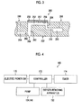
- Fig. 3 is a cross-sectional view illustrating a space structure of the ink chamber unit.
- a pressure chamber 252 is provided corresponding to each of the nozzles 204.
- the plane shape of the pressure chamber 252 is nearly a square shape, and a nozzle 204 and an ink inflow port 254 are provided on both corner ends thereof in a diagonal direction.
- Each pressure chamber 252 communicates with an individual flow path 259 through the ink inflow port 254, and each individual flow path 259 communicates with a common flow path 255.
- a nozzle flow path 260 that communicates with each pressure chamber 252 communicates with a common circulating flow path 264 through an individual circulating flow path 262.
- the inlet 266 and the outlet 268 are provided in the inkjet head 200.
- the inlet 266 communicates with the common flow path 255, and the outlet 268 communicates with the common circulating flow path 264.
- the inlet 266 and the outlet 268 of the inkjet head 200 communicate with each other through an ink flow path (internal flow path) including the common flow path 255, the individual flow path 259, the ink inflow port 254, the pressure chamber 252, the nozzle flow path 260, the individual circulating flow path 262, and the common circulating flow path 264.
- the individual circulating flow path 262 is configured to be connected to the vicinity of the nozzle 204 of the nozzle flow path 260. According to this configuration, the ink circulates in the vicinity of the nozzle 204, so that the ink inside the nozzles 204 is prevented from being thickened, and can be stably ejected.
- a diaphragm 256 configures the top surface of the pressure chamber 252 and also serves as a common electrode.
- the piezo-electric element 258 (an example of pressure generating means) including an individual electrode 257 is bonded to the diaphragm 256, and the piezo-electric element 258 is deformed by applying a driving voltage to the individual electrode 257 to eject the ink from the nozzle 204. If the ink is ejected, new ink is supplied from the common flow path 255 through the individual flow path 259 and the ink inflow port 254 to the pressure chamber 252.
- the piezo-electric element 258 is applied as means for generating ejecting force of the ink ejected from the nozzle 204 provided on the inkjet head 200, but a thermal method of providing a heater in the pressure chamber 252, using pressure generated by boiling the film with the heat from the heater, and ejecting the ink can also be applied.
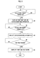
- Fig. 4 is a block diagram illustrating an electrical configuration of the ink circulation apparatus 100.
- the ink circulation apparatus 100 includes a power switch (SW) 170, a control unit 172, a timer 174, and the like.
- SW power switch
- the power switch 170 is a switch for inputting or cutting off electric power of the ink circulation apparatus 100.
- the user can release the electric power to the ink circulation apparatus 100 and run the ink circulation apparatus 100 by turning on the power switch 170. Further, the user can cut off the electric power of the ink circulation apparatus 100 and stop the ink circulation apparatus 100 by turning off the power switch 170.
- the control unit 172 (an example of control means) can control the ink circulation apparatus 100 in an integrated manner.
- the control unit 172 can control the start or the stop of the second pump 124 and the third pump 146 or the start or the stop of the oxygen removing apparatus 150 depending on a state of the power switch 170.
- the ink circulation apparatus 100 has a first mode of removing oxygen in the ink by operating the oxygen removing apparatus 150, and a second mode of not removing oxygen in the ink without operating the oxygen removing apparatus 150.
- the control unit 172 is configured to be capable of switching the first mode and the second mode.
- the timer 174 calculates the elapsed time under the instruction of the control unit 172 and outputs the calculated time to the control unit 172.
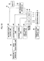
- the control unit 172 determines whether the power switch 170 is turned on by the user or not. If the power switch 170 is turned on, the process proceeds to step S2.
- the control unit 172 drives the second pump 124 and supplies the ink accumulated in the circulating tank 120 to the supply sub-tank 130.
- the supply sub-tank 130 is sealed, and the ink corresponding to the amount of the ink supplied to the supply sub-tank 130 is transferred from the supply sub-tank 130 to the oxygen removing apparatus 150.
- the oxygen removing apparatus 150 removes dissolved oxygen in the ink by flowing ink into the hollow fiber membrane and absorbing the gas by the pump from the outside (first mode, an example of an oxygen removing process).
- the ink from which dissolved oxygen is removed is supplied to the inlet 266 of the inkjet head 200 (an example of a supply process).
- the ink supplied from the inlet 266 to the inkjet head 200 flows through the common flow path 255, each pressure chamber 252 and each nozzle 204, and is discharged from the outlet 268 of the inkjet head 200.
- the control unit 172 drives the third pump 146, and transfers the ink discharged from the outlet 268 to the discharge sub-tank 140. Further, the discharge sub-tank 140 is sealed. The ink transferred to the discharge sub-tank 140 is collected to the circulating tank 120 (an example of a collecting process).
- control unit 172 When the ink accumulated in the circulating tank 120 is decreased, the control unit 172 operates the first pump 114 depending on the decreased amount and supplies the ink from the main tank 110 to the circulating tank 120.
- the control unit 172 determines whether the power switch 170 is turned off by the user or not. If the power switch 170 is turned off, the process proceeds to step S4.
- the control unit 172 stops the operation of the oxygen removing apparatus 150 (an example of a control process). In this manner, the ink from which oxygen is not removed is supplied to the inkjet head 200 (second mode). Further, the ink is discharged from the inkjet head 200, and the ink from which oxygen is not removed circulates in the ink circulation apparatus 100.
- the circulating tank 120, the supply sub-tank 130, and the discharge sub-tank 140 are configured so that the ink accumulated in the inside is in contact with the air. Accordingly, if the ink is circulated with the oxygen removing apparatus 150 stopped, the oxygen in the air penetrates into the ink so that the amount of dissolved oxygen in the ink is increased. Further, the increase rate of the amount of the dissolve oxygen is different depending on the area by which the ink is in contact with the air for each of the circulating tank 120, the supply sub-tank 130, and the discharge sub-tank 140.
- control unit 172 calculates the elapsed time from the stopping of the operation of the oxygen removing apparatus 150 with the timer 174.
- the control unit 172 determines whether the time from the stopping of the operation of the oxygen removing apparatus 150 has exceeded a first circulation time or not, based on the calculated time of the timer 174.
- the first circulation time is a period of time for the amount of the dissolved oxygen in the circulated ink to become a desired oxygen amount.
- the control unit 172 stores the first circulation time in a memory (not illustrated) in advance.
- step S6 When the time from the stopping of the operation of the oxygen removing apparatus 150 has exceeded the first circulation time, the process proceeds to step S6.
- control unit 172 stops the circulation of the ink by stopping operations of the second pump 124 and the third pump 146.
- the ink from which oxygen is removed by the oxygen removing apparatus 150 is generally supplied to the inkjet head 200 as a first mode. Accordingly, the generation of the cavitation in the inkjet head 200 is suppressed, and the stable ejecting performance can be obtained.
- the ink is circulated in a state in which the oxygen removing apparatus 150 is stopped, the circulation of the ink is stopped when the amount of the dissolved oxygen in the ink becomes the desired oxygen amount, and the electric power of the apparatus is cut off. Accordingly, even when the ink circulation apparatus 100 is stopped for a long period of time, the ink can be prevented from being thickened and the long lifespan of the ink can be obtained.
- oxygen in the ink is not removed by stopping the oxygen removing apparatus 150 as the second mode, but an embodiment in which oxygen in the ink is not removed by causing the ink to flow through a bypass flow path that bypasses the oxygen removing apparatus 150 is also possible.
- the supply sub-tank 130 and the discharge sub-tank 140 may include a vent valve that replaces the air enclosed in the inside.
- a vent valve that replaces the air enclosed in the inside.
- Fig. 6 is a diagram illustrating a result of the number of non-ejecting nozzles obtained from a continuous ejection experiment after the radical polymerization-type UV-curing ink for each ratio of an amount of dissolved oxygen filled in the inkjet head 200 and was left for 7 days.
- the ratio of the amount of the dissolved oxygen is a ratio of an amount of dissolved oxygen in the ink.
- the total number of the nozzles in the inkjet heads 200 was 256, and the initial number of the non-ejecting nozzles for each ratio of the amount of the dissolved oxygen was 0.
- the maximum size of an ink droplet that the nozzle 204 could eject was ejected at a frequency of 15 kHz
- a circulation time for the ratio of the amount of the dissolved oxygen in the ink to become 0.8 or more may be examined in advance, and stored in a memory (not illustrated). It is preferable that the circulation time be stored for each kind of ink.
- the increase rate of the amounts of the dissolved oxygen is different depending on the area by which the ink is in contact with the air for each of the circulating tank 120, the supply sub-tank 130, and the discharge sub-tank 140.
- the circulation time for the ratio of the amount of the dissolved oxygen in the ink to become 0.8 or more was 3 hours.
- Fig. 7 is a perspective view illustrating an external appearance of an inkjet recording apparatus 10.
- the inkjet recording apparatus 10 is a wide-format printer that forms a color image on a recording medium 12 by using ultraviolet ray curing ink (UV curing ink).
- the wide-format printer is an apparatus appropriate for recording a drawing in a wide range such as a large poster and wall surface advertisement for a commercial.
- a recording medium larger than an A3 size is referred to as a "wide format".
- the inkjet recording apparatus 10 includes an apparatus main body 20, and a supporting leg 22 that supports the apparatus main body 20.
- the apparatus main body 20 is provided with a drop-on-demand-type inkjet head 24 that ejects ink to the recording medium 12, a platen 26 that supports the recording medium 12, a guide mechanism 28 as means for moving a head, and a carriage 30.
- the guide mechanism 28 is provided over the platen 26 in a scanning direction (Y direction) perpendicular to a direction (X direction) of transporting the recording medium 12 and parallel to the medium supporting surface of the platen 26.
- the carriage 30 is supported to be capable of being moved in a reciprocating manner in the Y direction along the guide mechanism 28.
- the carriage 30 is provided with an inkjet head 24 together with preliminary curing light sources 32A and 32B and the main curing light sources 34A and 34B that radiate ultraviolet ray to the ink on the recording medium 12.
- the preliminary curing light sources 32A and 32B are light sources that radiate an ultraviolet ray for performing preliminary curing on ink to a degree in which neighboring droplets are not integrated with each other after ink droplets ejected from the inkjet head 24 are landed on the recording medium 12.
- the main curing light sources 34A and 34B are light sources that radiate ultraviolet rays for performing additional exposure after preliminary curing and completely curing the ink (main curing) for the last time.
- the inkjet head 24, the preliminary curing light sources 32A and 32B, and the main curing light sources 34A and 34B arranged on the carriage 30 are integrally (together) moved together with the carriage 30 along the guide mechanism 28.
- the recording medium 12 can be used as the recording medium 12, regardless of materials such as paper, unwoven fabric, vinyl chloride, synthetic chemical fibers, polyethylene, polyester, tarpaulin, and regardless of whether it is a permeable medium or a non-permeable medium.
- the recording medium 12 is fed in a rolled paper shape from the back surface side of the apparatus (see Fig. 8 ), and wound around a winding roller (not illustrated in Fig. 7 , reference number 44 of Fig. 8 ) on the front surface side of the apparatus after printing.
- Ink droplets are ejected from the inkjet head 24 to the recording medium 12 transported on the platen 26, and an ultraviolet ray is emitted from the preliminary curing light sources 32A and 32B and the main curing light sources 34A and 34B to the ink droplets attached onto the recording medium 12.
- a mounting portion 38 of ink cartridges 36 is provided on the front surface on the left of the apparatus main body 20 when viewed from the front side.
- the ink cartridges 36 are freely-changeable ink supply sources that accumulate the ultraviolet ray curing ink (corresponding to the main tank 110 of Fig. 1 ).
- the ink cartridges 36 are arranged respectively corresponding to colors of the ink used in the inkjet recording apparatus 10 according to the present embodiment.
- Each ink cartridge 36 for each color is connected to the inkjet head 24 through each of independently formed ink supply paths (not illustrated). If the remaining amounts of the colored ink are small, the ink cartridges 36 are changed.
- a maintenance unit of the inkjet head 24 is mounted on the right of the apparatus main body 20 viewed from the front side.
- the maintenance unit is provided with a cap for maintaining the moisture of the inkjet head 24 when printing is not performed and a wiping member (blade, web, and the like) for cleaning the nozzle surface (ink ejecting surface) of the inkjet head 24.
- the cap that caps the nozzle surface of the inkjet head 24 is provided with an ink receiver that receives ink ejected from the nozzles for maintenance.
- Fig. 8 is a diagram schematically illustrating a transporting path of a recording medium in the inkjet recording apparatus 10.
- the platen 26 is formed in a reversed tub shape (a shape formed by reversing a tub), and the top surface thereof becomes a supporting surface of the recording medium 12 (referred to as a recording medium supporting surface).
- a pair of nip rollers 40 which are recording medium transporting means for intermittently transporting the recording medium 12 is provided at the upstream (on the right in Fig. 8 ) in the direction (X direction) of transporting the recording medium in the vicinity of the platen 26.
- the nip rollers 40 transfer the recording medium 12 on the platen 26 in the X direction.
- the recording medium 12 that is fed from a feeding roller (transportation feeding roller) 42 included in the recording medium transporting means in a roller-to-roller method is intermittently transported in the X direction by the pair of nip rollers 40 provided at the entrance of the printing unit (on the upstream of the platen 26 in the direction of transporting the recording medium).
- the recording medium 12 that has reached the printing unit directly under the inkjet head 24 is subjected to printing by the inkjet head 24, and wound around the winding roller 44 after the printing.
- the guide 46 of the recording medium 12 is provided at the downstream of the printing unit in the direction of transporting the recording medium.
- the printing unit is provided with a temperature adjusting unit 50 for adjusting the temperature of the recording medium 12 during the printing on the back surface (a surface opposite to the surface supporting the recording medium 12) of the platen 26 at a position facing the inkjet head 24. If the recording medium 12 at the time of printing is adjusted to be in a predetermined temperature, a physical property such as the viscosity and the surface tension of the ink droplets landed on the recording medium 12 has a value as desired, and a desired dot diameter can be obtained. Further, if necessary, a heat pre-adjustment unit 52 may be provided at the upstream of the temperature adjusting unit 50, and a heat after-adjustment unit 54 may be provided at the downstream of the temperature adjusting unit 50.
- Fig. 9 is a plane perspective view illustrating an exemplary arrangement formation of the inkjet head 24, the preliminary curing light sources 32A and 32B, and the main curing light sources 34A and 34B arranged on the carriage 30.
- the inkjet head 24 is provided with head modules 24Y, 24M, 24C, 24K, 24LC, 24LM, 24CL, and 24W for ink of each color (an example of radical polymerization-type UV-curing ink of a plurality of colors) of yellow (Y), magenta (M), cyan (C), black (K), light cyan (LC), light magenta (LM), transparent ink (CL), and white (W).
- color an example of radical polymerization-type UV-curing ink of a plurality of colors
- Y yellow
- M magenta
- C cyan
- K black
- LC light cyan
- LM light magenta
- CL transparent ink
- W white
- Each of the head modules 24Y, 24M, 24C, 24K, 24LC, 24LM, 24CL, and 24W is provided with each of nozzle rows 61Y, 61M, 61C, 61K, 61LC, 61LM, 61CL, and 61W for ejecting ink of each color together with an ink inlet and an ink outlet (not illustrated, corresponding to the inlet 266 and the outlet 268 of the inkjet head 200). That is, each of the head modules 24Y, 24M, 24C, 24K, 24LC, 24LM, 24CL, and 24W correspond to the inkjet head 200 illustrated in Fig. 1 . Accordingly, the ink circulation apparatus 100 illustrated in Fig. 1 is provided with each of the head modules 24Y, 24M, 24C, 24K, 24LC, 24LM, 24CL, and 24W.
- nozzle rows are illustrated with dotted lines, and individual nozzles are not illustrated. Further, in the description below, the nozzle rows 61Y, 61M, 61C, 61K, 61LC, 61LM, 61CL, and 61W may be collectively referred to as a nozzle row indicated by reference number 61.
- the kinds of ink colors (the number of colors) or the combination of the colors is not limited to the present embodiment.
- an embodiment in which the nozzle rows LC and LM are omitted, an embodiment in which the nozzle rows CL and W are omitted, and an embodiment in which a nozzle row that ejects ink of a special color is added can be possible.
- an arrangement order of the nozzle rows for each color is not particularly limited.
- each of the nozzle rows 61 a plurality of nozzles are arranged in one row (linearly) in the X direction at constant intervals.
- an arrangement interval (nozzle pitch) of the nozzles included in each of the nozzle rows 61 is 254 ⁇ m (100 dpi)
- the number of nozzles included in one nozzle row 61 is 256
- the ejection frequency is 15 kHz
- the amount of ejection droplets can be divided into three kinds of 10 pl, 20 pl, and 30 pl by the change of drive waveforms. That is, three sizes of dots of a small dot, a middle dot, and a large dot can be formed.
- a method (piezojet method) of ejecting ink droplets by deformation of a piezo-electric element is employed.
- an embodiment (thermal jet method) in which bubbles are generated by heating ink using a heating unit (heating element) such as a heater, and ink droplets are ejected by the pressure can be employed.
- the preliminary curing light sources 32A and 32B are arranged on both of the left and right sides in the scanning direction (Y direction) of the inkjet head 24. Further, the main curing light sources 34A and 34B are arranged at the downstream of the inkjet head 24 in the direction (X direction) of transporting the recording medium.
- the ink droplets ejected from the nozzles of the inkjet head 24 and landed on the recording medium 12 is irradiated with ultraviolet rays for preliminary curing by the preliminary curing light source 32A (or 32B) that passes over the ink droplets right after the ink droplets are landed. Further, the ink droplets on the recording medium 12 that passes the printed region of the inkjet head 24 along with intermittent transport of the recording medium 12 are irradiated with ultraviolet rays for main curing by the main curing light sources 34A and 34B.
- the preliminary curing light sources 32A and 32B, and the main curing light sources 34A and 34B are always turned on while the inkjet recording apparatus 10 performs a printing operation.
- the preliminary curing light sources 32A and 32B each have structures in which a plurality of UV-LED elements 33 are lined.
- the two preliminary curing light sources 32A and 32B have the common structure.
- LED element arrangement in which six UV-LED elements 33 are arranged in one row in the X direction, as the preliminary curing light sources 32A and 32B is described, but the number and the arrangement formation of the LED elements are not limited thereto.
- a structure in which the plurality of LED elements are arranged in a matrix shape in the X and Y directions is also possible.
- the six UV-LED elements 33 are lined so that the UV irradiation can be performed on a region having the same width as a width Lw of the nozzle row of the inkjet head 24 at a time.
- the main curing light sources 34A and 34B each have a structure in which a plurality of UV-LED elements 35 are lined.
- the two main curing light sources 34A and 34B have the common structure.
- LED element arrangement (6x2) has a matrix shape with six UV-LED elements 35 in the Y direction and two UV-LED elements 35 in the X direction.
- the arrangement of the UV-LED elements 35 in the X direction relates to the swath width described below.
- the arrangement is determined so that the UV irradiation can be performed on a region having a 1/n width (n is a positive integer) of the width Lw of the nozzle row at a time, in one scanning by the carriage 30.
- the number and the arrangement formation of the LED element of the main curing light sources 34A and 34B are not limited by the embodiment illustrated in Fig. 9 . Further, light sources of the preliminary curing light sources 32A and 32B and the main curing light sources 34A and 34B are not limited to the UV-LED elements 33 and 35, and UV lamps or the like can be used.
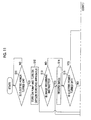
- Fig. 10 is a block diagram illustrating an electrical configuration of the inkjet recording apparatus 10.
- the inkjet recording apparatus 10 includes an image input interface 82, an image processing unit 84, an ejection control unit 86, an ink circulation control unit 88, a carriage control unit 92, a light source control unit 94, a transportation control unit 96, and a user interface 98.
- the image input interface 82 acquires image data via a wired or wireless communication interface.
- the image processing unit 84 performs a desired image process on input image data and converts the image data into print data (dot data).
- the dot data is generated by performing color conversion processing and half-toning processing on multi-level image data.
- the half-toning processing converts gray-scale image data having an M value (M ⁇ 3) into gray-scale image data having an N value (N ⁇ M).
- M ⁇ 3 gray-scale image data having an M value
- N ⁇ M gray-scale image data having an N value
- a conversion to binary (on/off of dots) dot image data is performed.
- multi-level quantization corresponding to the kinds of the dot size for example, three kinds such as a large dot, a middle dot, and a small dot can be performed.
- the binary or multi-level image data (dot data) obtained as described above is used as ink ejecting data (drop control data) that controls driving (on)/ non-driving (off) of each nozzle, and also the droplet amount (dot size) in the case of the multi-level image.
- the ejection control unit 86 generates an ejection control signal and controls the inkjet head 24 based on the dot data generated in the image processing unit 84. In this manner, ink is ejected from a corresponding nozzle of the inkjet head 24.
- the ink circulation control unit 88 controls the first pump 114, the second pump 124, the third pump 146, the oxygen removing apparatus 150, and the oxygen supplying apparatus 160 of the ink circulation apparatus 100, which are provided for each ink color, and the ink is circulated inside the head modules 24Y, 24M, 24C, 24K, 24LC, 24LM, 24CL, and 24W of the inkjet head 24 for each color. Further, the ink circulation control unit 88 circulates ink of each color regardless of whether the ink is ejected from the inkjet head 24 or not.
- the carriage control unit 92 controls the moving of the carriage 30 in the Y direction and performs reciprocating scanning of the inkjet head 24 in the Y direction.
- the light source control unit 94 controls the amount of light generated from the UV-LED elements 33 and 35 of the preliminary curing light sources 32A and 32B and the main curing light sources 34A and 34B.
- the transportation control unit 96 drives the nip rollers 40 and the winding roller 44, and controls the transport of the recording medium 12.
- the recording medium 12 transported on the platen 26 is intermittently transferred in the X direction in the unit of the swath width in accordance with the reciprocating scanning of the inkjet head 24 in the Y direction by the carriage 30.
- the recording means is configured with the ejection control unit 86, the carriage control unit 92, and the transportation control unit 96, and the recording means performs recording on the recording medium 12 by ejecting the ink from the nozzle of the inkjet head 24 while relatively moving the inkjet head 24 and the recording medium 12.
- the user interface (I/F) 98 includes an input unit that enables the user to operate the inkjet recording apparatus 10, an output unit that displays various types of alerts to the user, and a power switch for releasing or cutting off the electric power of the inkjet recording apparatus 10. Whether the power switch is turned on or off is input to the control unit 172 of the ink circulation apparatus 100.
- the ink is transferred to each of the head modules 24Y, 24M, 24C, 24K, 24LC, 24LM, 24CL, and 24W after oxygen in the ink is removed, the generation of the non-ejecting nozzles in each of the nozzle rows 61Y, 61M, 61C, 61K, 61LC, 61LM, 61CL, and 61W can be prevented and the ejection stabilization can be obtained.
- the control unit 172 of the ink circulation apparatus 100 determines whether the electric power of the inkjet recording apparatus 10 is turned on or not by the user interface 98. In the case in which the electric power is turned on, the process proceeds to step S12.
- the control unit 172 supplies ink from the circulating tank 120 to the inkjet head 200 by driving the second pump 124 (an example of a supply process), and collects ink from the inkjet head 200 to the circulating tank 120 by driving the third pump 146 (an example of a collecting process).
- the control unit 172 starts the oxygen removing apparatus 150, and removes oxygen in the ink to be supplied to the inkjet head 200 (first mode, an example of an oxygen removing process).
- control unit 172 When the ink accumulated in the circulating tank 120 is decreased, the control unit 172 operates the first pump 114 depending on the decreased amount, and supplies ink from the main tank 110 to the circulating tank 120.
- step S14 it is determined whether it is instructed to record an image by the user interface 98 or not. If instructed, the process proceeds to step S14, and if not, the process proceeds to step S 15.
- Image recording is performed according to the instruction to record an image. That is, the inkjet recording apparatus 10 transports the recording medium 12 by the transportation control unit 96, and causes the carriage 30 to perform reciprocating scanning in the Y direction by the carriage control unit 92.
- the ejection control unit 86 controls the inkjet head 24 based on the output data of the image processing unit 84 and ejects ink to the recording surface of the recording medium 12.
- the light source control unit 94 controls the UV-LED elements 33 and 35 of the preliminary curing light sources 32A and 32B and the main curing light sources 34A and 34B, and radiates ultraviolet rays to the ink droplets ejected to the recording medium 12.
- the control unit 172 determines whether the electric power of the inkjet recording apparatus 10 is turned off by the user interface 98 or not. If the electric power is turned off, the process proceeds to step S21, and if the electric power is not turned off, the process proceeds to step S16.
- the long period of time refers to a period of time during which an amount of dissolved oxygen in the ink is decreased by the oxygen removing apparatus 150, and the ink becomes thickened, by continuously circulating the ink. If a long period of time has not passed from the end of the image recording, the process proceeds to step S13, and the process repeats in the same manner. If a long period of time has passed, the process proceeds to step S 17.
- the control unit 172 stops the operation of the oxygen removing apparatus 150. That is, the ink is circulated without removing oxygen in the ink (second mode). Further, the elapsed time from when the operation of the oxygen removing apparatus 150 is stopped is calculated by the timer 174 (an example of a time calculation process).
- the control unit 172 determines whether the electric power of the inkjet recording apparatus 10 is turned off by the user interface 98 or not. If the electric power is turned off, the process proceeds to step S22, and if the electric power is not turned off, the process proceeds to step S 19.
- step S20 it is determined that whether the image recording is instructed by the user interface 98 or not. If instructed, the process proceeds to step S20, and if not, the process returns to step S 18, and repeats the operation in the same manner.
- the control unit 172 restarts the stopped operation of the oxygen removing apparatus 150. That is, the ink is supplied to the inkjet head 200 after oxygen in the ink is removed (first mode). Thereafter, the process proceeds to step S14, and the image recording is performed.
- step S15 if it is determined that the electric power is turned off, the control unit 172 stops the operation of the oxygen removing apparatus 150 (an example of an oxygen removing process). That is, the ink is circulated without removing oxygen in the ink (second mode). Further, the elapsed time after the operation of the oxygen removing apparatus 150 is stopped is calculated by the timer 174 (an example of a time calculating process).
- the control unit 172 determines whether the time from when the operation of the oxygen removing apparatus 150 is stopped has exceeded the first circulation time or not based on the calculated time of the timer 174.
- the first circulation time refers to a period of time for an amount of dissolved oxygen in the ink in circulation to become a desired oxygen amount similarly to step S5 of Fig. 5 .
- the first circulation time is a period of time when the amount of the dissolved oxygen in the ink becomes 0.8 or more, and it was 3 hours in the ink circulation apparatus 100 according to the present embodiment.
- the control unit 172 stores the first circulation time in the memory (not illustrated) in advance.
- step S23 If the time from when the operation of the oxygen removing apparatus 150 is stopped has exceeded the first circulation time, the process proceeds to step S23.
- the control unit 172 stops the second pump 124 and the third pump 146, and stops the circulation of the ink (an example of a circulation stopping process). Further, the electric power of the inkjet recording apparatus 10 is turned off and shut down.
- the ink from which oxygen is removed by the oxygen removing apparatus 150 is generally supplied to the inkjet head 200. Accordingly, the cavitation is suppressed from being generated inside the inkjet head 200, and a stable ejecting performance can be obtained.
- the circulation of the ink is stopped when the dissolved oxygen in the ink becomes the desired oxygen amount and the electric power is cut off. Accordingly, even when the inkjet recording apparatus 10 is stopped for a long period of time, the thickening of the ink can prevented and the long lifespan of the ink can be obtained.
- the ink When the image recording is not performed for a long period of time with the electric power of the inkjet recording apparatus 10 being turned on, the ink is circulated in a state in which the oxygen removing apparatus 150 is stopped so that the thickening of the ink is suppressed. For example, even when a standby mode or a sleep mode in which an image is not formed is started with the electric power of the inkjet recording apparatus 10 being turned on, the ink may be circulated in a state in which the oxygen removing apparatus 150 is stopped.
- the present specification is described with reference to the inkjet recording apparatus that ejects colored ink suitable for the application of the graphic print.
- the present invention is not limited thereto, and can be applied to an image forming apparatus that ejects resist ink (heat resistant covering material) for printed wiring, dispersion liquid in which conductive fine particles are dispersed in a dispersion medium, ink used for manufacturing a color filter, and the like.
Landscapes
- Ink Jet (AREA)
Abstract
Description
- The present invention relates to an ink circulation apparatus, an ink circulation method, and an inkjet recording apparatus, and particularly to a technique of preventing a defected nozzle of the inkjet head from being generated.
- In the inkjet recording apparatus, if bubbles or dissolved gas exists in ink, the ink may not be sufficiently compressed when being ejected, so the ejection property is decreased, and the ink flow is not stable. Accordingly, dot omission or defective printing may occur.
- In order to solve the problems above, in
JP1993-17712 JP-H5-17712 - Meanwhile, it is known that in radical polymerization-type UV-curing ink, when removing gas from the ink, an oxygen amount in the ink is decreased and the ink is thickened (viscosity is increased)(
JP2008-132701 - In order to prevent the radical polymerization-type UV-curing ink from being thickened,
JP2006-110780 - According to the technique, if the inkjet head performs the ejection operation, the ink from which the dissolved gas is removed fills the ink chamber, so bubbles caused by dissolved gas in the ink chamber can be suppressed from being generated. If an inkjet recording apparatus does not perform the ejection operation, the ink to which gas is supplied and in which dissolved gas is increased fills the ink chamber, so the ink in the ink chamber is not easily cured, and particles caused by the cured ink can be suppressed from being generated.
- Ink is thickened when a solvent of ink evaporates at a nozzle. A technique of providing an ink circulating path in the vicinity of the nozzle and circulating the ink in the nozzle in order to prevent the ink from being thickened has been known. However, the technique of circulating the ink in this manner may not be applied to the technique of
JP2006-110780 - In view of the circumstances as above, an object of the invention is to provide an ink circulation apparatus, an ink circulation method, and an inkjet recording apparatus that can simultaneously prevent the generation of bubbles in ink, the thickening of ink, and the generation of particles when radical polymerization-type UV-curing ink is circulated in an inkjet head.
- To achieve the above-described object, there is provided an ink circulation apparatus, including: an ink tank that accumulates radical polymerization-type UV-curing ink so as to be in contact with gas including at least oxygen; a supplying flow path that communicates with the ink tank and a supply port of an inkjet head including the supply port to which the radical polymerization-type UV-curing ink is supplied, a nozzle that ejects the radical polymerization-type UV-curing ink, and a discharge port from which the radical polymerization-type UV-curing ink that is not ejected from the nozzle is discharged; a supply pump that is provided in the supplying flow path, and supplies the radical polymerization-type UV-curing ink accumulated in the ink tank to the inkjet head; oxygen removing means that is provided in the supplying flow path, and removes oxygen from the radical polymerization-type UV-curing ink; a discharging flow path that communicates with the discharge port of the inkjet head and the ink tank; a collecting pump that is provided in the discharging flow path and collects the radical polymerization-type UV-curing ink discharged from the discharge port to the ink tank; and control means that changes a mode between a first mode of removing oxygen from the radical polymerization-type UV-curing ink by the oxygen removing means and a second mode of not removing oxygen from the radical polymerization-type UV-curing ink and changes a mode from the first mode to the second mode before electric power of the apparatus is cut off.
- According to this aspect, since oxygen is removed from radical polymerization-type UV-curing ink to be supplied to the inkjet head in the first mode, bubbles are prevented from being generated in the inkjet head so dot omission or defective printing may not occur. Further, before electric power of the apparatus is cut off, since ink is circulated without removing oxygen from the ink by changing a mode from the first mode to the second mode, the gas including at least oxygen and the ink are in contact with each other in the ink tank and oxygen is supplied to the ink. Therefore, the ink is not thickened, and the particles are not generated. In this manner, it is possible to prevent the ink from generating bubbles and generating particles at the same time.
- In the ink circulation apparatus, it is preferable that the control means cuts off the electric power after an amount of dissolved oxygen of the radical polymerization-type UV-curing ink reaches a desired oxygen amount from when a mode is changed to the second mode. According to this, even when the apparatus has not been used for a long period of time, the thickening of the ink can be prevented and the long lifespan of the ink can be obtained.
- In the ink circulation apparatus, it is preferable that the control means obtain in advance a circulation time required for an amount of dissolved oxygen of the radical polymerization-type UV-curing ink to become a desired oxygen amount, and the electric power be cut off after the circulation time has passed from when a mode is changed to the second mode. According to this, an amount of dissolved oxygen in the ink can be set to a desired oxygen amount appropriately.
- It is preferable that the ink circulation apparatus further include: a power switch, in which the control means changes a mode from the first mode to the second mode when the power switch is turned off. In this manner, the invention can be applied even when the electric power of the apparatus is cut off according to the operation of the power switch.
- It is preferable that the ink circulation apparatus further include: a supply sub-tank that is provided in the supplying flow path, and retains the radical polymerization-type UV-curing ink so as to be in contact with gas including at least oxygen. According to this, an amount of dissolved oxygen in the ink can be set to a desired oxygen amount in a short period of time.
- In the ink circulation apparatus, it is preferable that the oxygen removing means be provided between the supply sub-tank and the inkjet head. Further, in the ink circulation apparatus, it is preferable that the oxygen removing means remove oxygen from the radical polymerization-type UV-curing ink using a hollow fiber membrane. According to this, oxygen in the ink can be removed appropriately.
- It is preferable that the ink circulation apparatus further include: a discharge sub-tank that is provided in the discharging flow path, and retains the radical polymerization-type UV-curing ink so as to be in contact with gas including at least oxygen. According to this, an amount of dissolved oxygen in the ink can be set to a desired oxygen amount in a short period of time.
- It is preferable that the ink circulation apparatus further include: a main tank that accumulates the radical polymerization-type UV-curing ink; a main flow path that communicates with the main tank and the ink tank; and a main pump that is provided in the main flow path and supplies the radical polymerization-type UV-curing ink accumulated in the main tank to the ink tank. According to this, ink in the ink tank can be supplemented.
- To achieve the above-described object, there is provided an inkjet recording apparatus, including: an ink circulation apparatus that includes an ink tank that accumulates radical polymerization-type UV-curing ink so as to be in contact with gas including at least oxygen, a supplying flow path that communicates with the ink tank and a supply port of an inkjet head including the supply port to which the radical polymerization-type UV-curing ink is supplied, a nozzle that ejects the radical polymerization-type UV-curing ink, and a discharge port from which the radical polymerization-type UV-curing ink that is not ejected from the nozzle is discharged, a supply pump that is provided in the supplying flow path, and supplies the radical polymerization-type UV-curing ink accumulated in the ink tank to the inkjet head, oxygen removing means that is provided in the supplying flow path, and removes oxygen from the radical polymerization-type UV-curing ink supplied to the inkjet head, a discharging flow path that communicates with the discharge port of the inkjet head and the ink tank, a collecting pump that is provided in the discharging flow path and collects the radical polymerization-type UV-curing ink discharged from the discharge port to the ink tank, and control means that stops the oxygen removing means if a switch is operated, and stops the supply pump and the collecting pump after the radical polymerization-type UV-curing ink is circulated for a predetermined period of time by the supply pump and the collecting pump; an inkjet head; recording means that lands ink on a recording medium by ejecting ink from a nozzle of the inkjet head while relatively moving the inkjet head and the recording medium; and curing means that cures the landed ink by irradiating the ink with ultraviolet rays.
- According to this aspect, since oxygen is removed from radical polymerization-type UV-curing ink to be supplied to the inkjet head in the first mode, bubbles in the inkjet head can be suppressed from being generated, and dot omission or defective printing may not occur. Further, since before electric power of the apparatus is cut off, ink is circulated without removing oxygen from the ink by changing a mode from the first mode to the second mode, the ink is in contact with the gas including at least oxygen in the ink tank and oxygen is supplied to the ink. Therefore, the ink is not thickened, and the particles are not generated. In this manner, it is possible to prevent the ink from generating bubbles and generating particles at the same time.
- In the ink circulation apparatus, it is preferable that the control means change a mode to the second mode when the recording means does not eject ink from the nozzle for a long period of time. In this manner, when the recording means does not eject ink from the nozzle for a long period of time, removing oxygen in the ink is stopped and oxygen is supplied to the ink so that the thickening of the ink can be prevented and the long lifespan of the ink can be obtained.
- To achieve the above-described object, there is provided an ink circulation method including: supplying radical polymerization-type UV-curing ink, from an ink tank that accumulates the radical polymerization-type UV-curing ink so as to be in contact with gas including at least oxygen, to a supply port of an inkjet head including the supply port to which the radical polymerization-type UV-curing ink is supplied, a nozzle that ejects the radical polymerization-type UV-curing ink, and a discharge port from which the radical polymerization-type UV-curing ink that is not ejected from the nozzle is discharged; removing oxygen from the radical polymerization-type UV-curing ink to be supplied to the inkjet head; collecting the radical polymerization-type UV-curing ink discharged from the discharge port of the inkjet head to the ink tank; and changing a mode between a first mode of removing oxygen from the radical polymerization-type UV-curing ink by the removing of the oxygen and a second mode of not removing oxygen from the radical polymerization-type UV-curing ink and changing a mode from the first mode to the second mode before electric power of the apparatus is cut off.
- According to the invention, it is possible to prevent the ink from generating bubbles and generating particles at the same time so that the ejecting performance can be stabilized and the long lifespan of the ink can be obtained.
-
-
Fig. 1 is a diagram schematically illustrating a configuration of an ink circulation apparatus. -
Figs. 2A and 2B are diagrams illustrating an inkjet head. -
Fig. 3 is a cross-sectional view illustrating a steric structure of an ink chamber unit. -
Fig. 4 is a block diagram illustrating an electrical configuration of the ink circulation apparatus. -
Fig. 5 is a flow chart illustrating an operation of the ink circulation apparatus. -
Fig. 6 is a diagram illustrating a relationship between the ratio of an amount of dissolved oxygen and the number of non-ejecting nozzles after being left for 7 days. -
Fig. 7 is a perspective view illustrating an external appearance of an inkjet recording apparatus. -
Fig. 8 is a diagram schematically illustrating a transporting path of a recording medium in the inkjet recording apparatus. -
Fig. 9 is a plane perspective view illustrating an exemplary arrangement formation on a carriage. -
Fig. 10 is a block diagram illustrating an electrical configuration of the inkjet recording apparatus. -
Fig. 11 is a flow chart illustrating an operation of the inkjet recording apparatus. - Hereinafter, preferred embodiments of the invention are described with reference to the accompanying drawings.
-
Fig. 1 is a diagram schematically illustrating a configuration of an ink circulation apparatus according to an embodiment of the invention. Anink circulation apparatus 100 circulates ink inside aninkjet head 200 that ejects radical polymerization-type UV-curing ink (hereinafter, simply referred to as "ink"), and includes amain tank 110 that mainly accumulates new ink, a circulatingtank 120 that accumulates circulated ink, asupply sub-tank 130 that temporarily accumulates ink supplied from the circulatingtank 120 to theinkjet head 200, and adischarge sub-tank 140 that temporarily accumulates ink collected from theinkjet head 200 to the circulatingtank 120. - The radical polymerization-type UV-curing ink used in the present embodiment includes an initiator of radical polymerization, as a UV-curing material. In the radical polymerization-type UV-curing ink, oxygen inhibits a polymerizing reaction.
- The
main tank 110 and the circulating tank 120 (an example of an ink tank) communicate with each other through a first flow path 112 (an example of a main flow path). Thefirst flow path 112 is provided with a first pump 114 (an example of a main pump) that applies pressure into thefirst flow path 112, and transfers the ink accumulated in themain tank 110 to the circulatingtank 120. - The circulating
tank 120 is exposed to the atmosphere, and configured so that the ink accumulated in the circulatingtank 120 is in contact with the air (an example of the gas including at least oxygen). - The circulating
tank 120 and thesupply sub-tank 130 communicate with each other through a second flow path 122 (an example of a supplying flow path). Thesecond flow path 122 is provided with a second pump 124 (an example of a supply pump) that applies pressure into thesecond flow path 122 and transfers ink accumulated in the circulatingtank 120 to thesupply sub-tank 130. - The
supply sub-tank 130 operates as a pressure buffer unit that decreases pulsation of the second pump 124. Thesupply sub-tank 130 is configured so that the ink accumulated in thesupply sub-tank 130 is in contact with the air enclosed in the inside. - The
supply sub-tank 130 and an inlet 266 (an example of a supply port) of theinkjet head 200 communicate with each other through athird flow path 126. Thethird flow path 126 is provided with an oxygen removing apparatus 150 (an example of an oxygen removing means) that removes oxygen in the ink flowing through thethird flow path 126. - The
oxygen removing apparatus 150 includes a hollow fiber membrane that gas penetrates but liquid does not substantially penetrate. Theoxygen removing apparatus 150 causes the ink to pass on one side of the hollow fiber membrane, and absorbs the ink by a pump on the other side thereof so as to remove dissolved oxygen in the gas in a process in which the ink passes through the hollow fiber membrane. The phrase "liquid does not substantially penetrate the hollow fiber membrane" means that liquid does not penetrate the hollow fiber membrane to a degree in which gas and liquid can be divided and dissolved oxygen can be removed from the ink. In particular, in addition to a case in which liquid does not penetrate the hollow fiber membrane at all, the phrase includes a case in which liquid partially penetrates the hollow fiber membrane (preferably 0.5% or less). In the present embodiment, the hollow fiber membrane of theoxygen removing apparatus 150 is formed to be a cylindrical shape. Further, a method of removing dissolved oxygen in the ink is not limited to a method of using a hollow fiber, and a known method can be used. - The
inlet 266 and theoutlet 268 of theinkjet head 200 communicate with each other inside theinkjet head 200. Theinkjet head 200 includes a plurality of nozzles (reference number 204 inFig. 2A and 2B ) in thenozzle surface 202 that faces a recording surface of the recording medium, ejects ink from the nozzles, and drops the ink onto the recording surface of the recording medium. The back pressure of the nozzles is determined by a difference between the pressure inside thesupply sub-tank 130 and pressure inside thedischarge sub-tank 140. - The outlet 268 (an example of a discharge port) of the
inkjet head 200 and thedischarge sub-tank 140 communicate with each other through afourth flow path 142. - The
discharge sub-tank 140 operates as a pressure buffer unit that decreases pulsation of thethird pump 146 described below. Further, thedischarge sub-tank 140 is configured so that the ink retained in the inside is in contact with the air enclosed in the inside. - The
discharge sub-tank 140 and the circulatingtank 120 communicate with each other through a fifth flow path 144 (an example of a discharging flow path). Thefifth flow path 144 is provided with the third pump 146 (an example of a collecting pump). Thethird pump 146 applies pressure inside thefifth flow path 144, and transfers ink discharged from theoutlet 268 of theinkjet head 200 through thedischarge sub-tank 140 to the circulatingtank 120. - Usually, an ink circulating system includes the circulating
tank 120, thesupply sub-tank 130, theinkjet head 200, thedischarge sub-tank 140, thesecond flow path 122, thethird flow path 126, thefourth flow path 142, and thefifth flow path 144, and the ink is circulated in the ink circulating system. Themain tank 110 is provided outside the ink circulating system. -
Fig. 2A is a diagram illustrating theinkjet head 200 seen from anozzle surface 202. Thenozzle surface 202 of theinkjet head 200 is formed to be a plane surface. A plurality ofnozzles 204 which are ink droplet ejection holes are provided in thenozzle surface 202. -
Fig. 2B is a flow path configuration diagram illustrating a flow path configuration inside theinkjet head 200, andFig. 3 is a cross-sectional view illustrating a space structure of the ink chamber unit. Apressure chamber 252 is provided corresponding to each of thenozzles 204. The plane shape of thepressure chamber 252 is nearly a square shape, and anozzle 204 and anink inflow port 254 are provided on both corner ends thereof in a diagonal direction. Eachpressure chamber 252 communicates with anindividual flow path 259 through theink inflow port 254, and eachindividual flow path 259 communicates with acommon flow path 255. Anozzle flow path 260 that communicates with eachpressure chamber 252 communicates with a common circulatingflow path 264 through an individual circulatingflow path 262. Theinlet 266 and theoutlet 268 are provided in theinkjet head 200. Theinlet 266 communicates with thecommon flow path 255, and theoutlet 268 communicates with the common circulatingflow path 264. - That is, the
inlet 266 and theoutlet 268 of theinkjet head 200 communicate with each other through an ink flow path (internal flow path) including thecommon flow path 255, theindividual flow path 259, theink inflow port 254, thepressure chamber 252, thenozzle flow path 260, the individual circulatingflow path 262, and the common circulatingflow path 264. Therefore, a portion of the ink supplied from the outside of theinkjet head 200 to theinlet 266 is ejected from eachnozzle 204, and the remaining ink is discharged from theoutlet 268 to the outside of theinkjet head 200 sequentially through thecommon flow path 255, theindividual flow path 259, thenozzle flow path 260, the individual circulatingflow path 262, and the common circulatingflow path 264. - As illustrated in
Fig. 3 , it is preferable that the individual circulatingflow path 262 is configured to be connected to the vicinity of thenozzle 204 of thenozzle flow path 260. According to this configuration, the ink circulates in the vicinity of thenozzle 204, so that the ink inside thenozzles 204 is prevented from being thickened, and can be stably ejected. - A
diaphragm 256 configures the top surface of thepressure chamber 252 and also serves as a common electrode. The piezo-electric element 258 (an example of pressure generating means) including anindividual electrode 257 is bonded to thediaphragm 256, and the piezo-electric element 258 is deformed by applying a driving voltage to theindividual electrode 257 to eject the ink from thenozzle 204. If the ink is ejected, new ink is supplied from thecommon flow path 255 through theindividual flow path 259 and theink inflow port 254 to thepressure chamber 252. - In the present example, the piezo-
electric element 258 is applied as means for generating ejecting force of the ink ejected from thenozzle 204 provided on theinkjet head 200, but a thermal method of providing a heater in thepressure chamber 252, using pressure generated by boiling the film with the heat from the heater, and ejecting the ink can also be applied. -
Fig. 4 is a block diagram illustrating an electrical configuration of theink circulation apparatus 100. As illustrated inFig. 4 , theink circulation apparatus 100 includes a power switch (SW) 170, acontrol unit 172, atimer 174, and the like. - The
power switch 170 is a switch for inputting or cutting off electric power of theink circulation apparatus 100. The user can release the electric power to theink circulation apparatus 100 and run theink circulation apparatus 100 by turning on thepower switch 170. Further, the user can cut off the electric power of theink circulation apparatus 100 and stop theink circulation apparatus 100 by turning off thepower switch 170. - The control unit 172 (an example of control means) can control the
ink circulation apparatus 100 in an integrated manner. Thecontrol unit 172 can control the start or the stop of the second pump 124 and thethird pump 146 or the start or the stop of theoxygen removing apparatus 150 depending on a state of thepower switch 170. - The
ink circulation apparatus 100 has a first mode of removing oxygen in the ink by operating theoxygen removing apparatus 150, and a second mode of not removing oxygen in the ink without operating theoxygen removing apparatus 150. Thecontrol unit 172 is configured to be capable of switching the first mode and the second mode. - The
timer 174 calculates the elapsed time under the instruction of thecontrol unit 172 and outputs the calculated time to thecontrol unit 172. - An operation (an example of an ink circulation method) of the
ink circulation apparatus 100 configured as described above is described with reference to a flowchart ofFig. 5 . - The
control unit 172 determines whether thepower switch 170 is turned on by the user or not. If thepower switch 170 is turned on, the process proceeds to step S2. - If the
power switch 170 is turned on, thecontrol unit 172 drives the second pump 124 and supplies the ink accumulated in the circulatingtank 120 to thesupply sub-tank 130. Thesupply sub-tank 130 is sealed, and the ink corresponding to the amount of the ink supplied to thesupply sub-tank 130 is transferred from thesupply sub-tank 130 to theoxygen removing apparatus 150. - The
oxygen removing apparatus 150 removes dissolved oxygen in the ink by flowing ink into the hollow fiber membrane and absorbing the gas by the pump from the outside (first mode, an example of an oxygen removing process). The ink from which dissolved oxygen is removed is supplied to theinlet 266 of the inkjet head 200 (an example of a supply process). - The ink supplied from the
inlet 266 to theinkjet head 200 flows through thecommon flow path 255, eachpressure chamber 252 and eachnozzle 204, and is discharged from theoutlet 268 of theinkjet head 200. Thecontrol unit 172 drives thethird pump 146, and transfers the ink discharged from theoutlet 268 to thedischarge sub-tank 140. Further, thedischarge sub-tank 140 is sealed. The ink transferred to thedischarge sub-tank 140 is collected to the circulating tank 120 (an example of a collecting process). - When the ink accumulated in the circulating
tank 120 is decreased, thecontrol unit 172 operates thefirst pump 114 depending on the decreased amount and supplies the ink from themain tank 110 to the circulatingtank 120. - The
control unit 172 determines whether thepower switch 170 is turned off by the user or not. If thepower switch 170 is turned off, the process proceeds to step S4. - If the
power switch 170 is turned off, thecontrol unit 172 stops the operation of the oxygen removing apparatus 150 (an example of a control process). In this manner, the ink from which oxygen is not removed is supplied to the inkjet head 200 (second mode). Further, the ink is discharged from theinkjet head 200, and the ink from which oxygen is not removed circulates in theink circulation apparatus 100. - The circulating
tank 120, thesupply sub-tank 130, and thedischarge sub-tank 140 are configured so that the ink accumulated in the inside is in contact with the air. Accordingly, if the ink is circulated with theoxygen removing apparatus 150 stopped, the oxygen in the air penetrates into the ink so that the amount of dissolved oxygen in the ink is increased. Further, the increase rate of the amount of the dissolve oxygen is different depending on the area by which the ink is in contact with the air for each of the circulatingtank 120, thesupply sub-tank 130, and thedischarge sub-tank 140. - Further, the
control unit 172 calculates the elapsed time from the stopping of the operation of theoxygen removing apparatus 150 with thetimer 174. - The
control unit 172 determines whether the time from the stopping of the operation of theoxygen removing apparatus 150 has exceeded a first circulation time or not, based on the calculated time of thetimer 174. - The first circulation time is a period of time for the amount of the dissolved oxygen in the circulated ink to become a desired oxygen amount. The
control unit 172 stores the first circulation time in a memory (not illustrated) in advance. - When the time from the stopping of the operation of the
oxygen removing apparatus 150 has exceeded the first circulation time, the process proceeds to step S6. - If the time from the stopping of the operation of the
oxygen removing apparatus 150 has exceeded the first circulation time, thecontrol unit 172 stops the circulation of the ink by stopping operations of the second pump 124 and thethird pump 146. - Subsequently, all of the electric power of the
ink circulation apparatus 100 is cut off (shut down). - In this manner, the ink from which oxygen is removed by the
oxygen removing apparatus 150 is generally supplied to theinkjet head 200 as a first mode. Accordingly, the generation of the cavitation in theinkjet head 200 is suppressed, and the stable ejecting performance can be obtained. - If the
power switch 170 is turned off by the user, as a second mode, the ink is circulated in a state in which theoxygen removing apparatus 150 is stopped, the circulation of the ink is stopped when the amount of the dissolved oxygen in the ink becomes the desired oxygen amount, and the electric power of the apparatus is cut off. Accordingly, even when theink circulation apparatus 100 is stopped for a long period of time, the ink can be prevented from being thickened and the long lifespan of the ink can be obtained. - According to the present embodiment, oxygen in the ink is not removed by stopping the
oxygen removing apparatus 150 as the second mode, but an embodiment in which oxygen in the ink is not removed by causing the ink to flow through a bypass flow path that bypasses theoxygen removing apparatus 150 is also possible. - Further, the
supply sub-tank 130 and thedischarge sub-tank 140 may include a vent valve that replaces the air enclosed in the inside. In addition, when replacing the air, it is preferable to prevent the flow of the ink in thethird flow path 126 and thefourth flow path 142 by the valve and the like. -
Fig. 6 is a diagram illustrating a result of the number of non-ejecting nozzles obtained from a continuous ejection experiment after the radical polymerization-type UV-curing ink for each ratio of an amount of dissolved oxygen filled in theinkjet head 200 and was left for 7 days. Here, when the amount of the dissolved oxygen in the ink from which the gas was not removed under the condition of room temperature and 1 atmosphere pressure was set to be "1", the ratio of the amount of the dissolved oxygen is a ratio of an amount of dissolved oxygen in the ink. In addition, the total number of the nozzles in the inkjet heads 200 was 256, and the initial number of the non-ejecting nozzles for each ratio of the amount of the dissolved oxygen was 0. In addition, in the continuous ejection experiment, the maximum size of an ink droplet that thenozzle 204 could eject was ejected at a frequency of 15 kHz - As illustrated in
Fig. 6 , when the ratio of the amount of the dissolved oxygen was 0, that is, when oxygen in the ink was completely removed from the ink, the number of the non-ejecting nozzles after being left for 7 days was 55. Further, when the ratios of the amounts of the dissolved oxygen were "0.2", "0.4", and "0.6", the numbers of the non-ejecting nozzles after being left for 7 days were "42", "20", and "5", respectively. The greater the ratio of the amount of the dissolved oxygen, the smaller the number of the non-ejecting nozzles. Further, when the ratios of the amount of the dissolved oxygen were "0.8" and "1 (saturated state)", the number of the non-ejecting nozzles after being left for 7 days were equally "2". - From this result, it was found that it was preferable to circulate the ink until the ratio of the amount of the dissolved oxygen in the ink become equal to or more than 0.8, in step S5 in
Fig. 5 . - Accordingly, for example, a circulation time for the ratio of the amount of the dissolved oxygen in the ink to become 0.8 or more may be examined in advance, and stored in a memory (not illustrated). It is preferable that the circulation time be stored for each kind of ink.
- As described above, the increase rate of the amounts of the dissolved oxygen is different depending on the area by which the ink is in contact with the air for each of the circulating
tank 120, thesupply sub-tank 130, and thedischarge sub-tank 140. In theink circulation apparatus 100 according to the present embodiment, the circulation time for the ratio of the amount of the dissolved oxygen in the ink to become 0.8 or more was 3 hours. - Subsequently, an inkjet recording apparatus to which the
ink circulation apparatus 100 according to the present embodiment is applied is described. -
Fig. 7 is a perspective view illustrating an external appearance of aninkjet recording apparatus 10. Theinkjet recording apparatus 10 is a wide-format printer that forms a color image on arecording medium 12 by using ultraviolet ray curing ink (UV curing ink). The wide-format printer is an apparatus appropriate for recording a drawing in a wide range such as a large poster and wall surface advertisement for a commercial. Here, a recording medium larger than an A3 size is referred to as a "wide format". - The
inkjet recording apparatus 10 includes an apparatusmain body 20, and a supportingleg 22 that supports the apparatusmain body 20. The apparatusmain body 20 is provided with a drop-on-demand-type inkjet head 24 that ejects ink to therecording medium 12, aplaten 26 that supports therecording medium 12, aguide mechanism 28 as means for moving a head, and acarriage 30. - The
guide mechanism 28 is provided over theplaten 26 in a scanning direction (Y direction) perpendicular to a direction (X direction) of transporting therecording medium 12 and parallel to the medium supporting surface of theplaten 26. Thecarriage 30 is supported to be capable of being moved in a reciprocating manner in the Y direction along theguide mechanism 28. Thecarriage 30 is provided with aninkjet head 24 together with preliminary curinglight sources curing light sources recording medium 12. - The preliminary
curing light sources inkjet head 24 are landed on therecording medium 12. The maincuring light sources - The
inkjet head 24, the preliminarycuring light sources curing light sources carriage 30 are integrally (together) moved together with thecarriage 30 along theguide mechanism 28. - Various kinds of media can be used as the
recording medium 12, regardless of materials such as paper, unwoven fabric, vinyl chloride, synthetic chemical fibers, polyethylene, polyester, tarpaulin, and regardless of whether it is a permeable medium or a non-permeable medium. Therecording medium 12 is fed in a rolled paper shape from the back surface side of the apparatus (seeFig. 8 ), and wound around a winding roller (not illustrated inFig. 7 ,reference number 44 ofFig. 8 ) on the front surface side of the apparatus after printing. Ink droplets are ejected from theinkjet head 24 to therecording medium 12 transported on theplaten 26, and an ultraviolet ray is emitted from the preliminarycuring light sources curing light sources recording medium 12. - In
Fig. 7 , a mountingportion 38 ofink cartridges 36 is provided on the front surface on the left of the apparatusmain body 20 when viewed from the front side. Theink cartridges 36 are freely-changeable ink supply sources that accumulate the ultraviolet ray curing ink (corresponding to themain tank 110 ofFig. 1 ). Theink cartridges 36 are arranged respectively corresponding to colors of the ink used in theinkjet recording apparatus 10 according to the present embodiment. Eachink cartridge 36 for each color is connected to theinkjet head 24 through each of independently formed ink supply paths (not illustrated). If the remaining amounts of the colored ink are small, theink cartridges 36 are changed. - Further, though not illustrated in the drawings, a maintenance unit of the
inkjet head 24 is mounted on the right of the apparatusmain body 20 viewed from the front side. The maintenance unit is provided with a cap for maintaining the moisture of theinkjet head 24 when printing is not performed and a wiping member (blade, web, and the like) for cleaning the nozzle surface (ink ejecting surface) of theinkjet head 24. The cap that caps the nozzle surface of theinkjet head 24 is provided with an ink receiver that receives ink ejected from the nozzles for maintenance. -
Fig. 8 is a diagram schematically illustrating a transporting path of a recording medium in theinkjet recording apparatus 10. As illustrated inFig. 8 , theplaten 26 is formed in a reversed tub shape (a shape formed by reversing a tub), and the top surface thereof becomes a supporting surface of the recording medium 12 (referred to as a recording medium supporting surface). A pair of niprollers 40 which are recording medium transporting means for intermittently transporting therecording medium 12 is provided at the upstream (on the right inFig. 8 ) in the direction (X direction) of transporting the recording medium in the vicinity of theplaten 26. The niprollers 40 transfer therecording medium 12 on theplaten 26 in the X direction. - The
recording medium 12 that is fed from a feeding roller (transportation feeding roller) 42 included in the recording medium transporting means in a roller-to-roller method is intermittently transported in the X direction by the pair of niprollers 40 provided at the entrance of the printing unit (on the upstream of theplaten 26 in the direction of transporting the recording medium). Therecording medium 12 that has reached the printing unit directly under theinkjet head 24 is subjected to printing by theinkjet head 24, and wound around the windingroller 44 after the printing. Theguide 46 of therecording medium 12 is provided at the downstream of the printing unit in the direction of transporting the recording medium. - The printing unit is provided with a
temperature adjusting unit 50 for adjusting the temperature of therecording medium 12 during the printing on the back surface (a surface opposite to the surface supporting the recording medium 12) of theplaten 26 at a position facing theinkjet head 24. If therecording medium 12 at the time of printing is adjusted to be in a predetermined temperature, a physical property such as the viscosity and the surface tension of the ink droplets landed on therecording medium 12 has a value as desired, and a desired dot diameter can be obtained. Further, if necessary, aheat pre-adjustment unit 52 may be provided at the upstream of thetemperature adjusting unit 50, and a heat after-adjustment unit 54 may be provided at the downstream of thetemperature adjusting unit 50. -
Fig. 9 is a plane perspective view illustrating an exemplary arrangement formation of theinkjet head 24, the preliminarycuring light sources curing light sources carriage 30. - The
inkjet head 24 is provided withhead modules - Each of the
head modules nozzle rows inlet 266 and theoutlet 268 of the inkjet head 200). That is, each of thehead modules inkjet head 200 illustrated inFig. 1 . Accordingly, theink circulation apparatus 100 illustrated inFig. 1 is provided with each of thehead modules - In
Fig. 9 , nozzle rows are illustrated with dotted lines, and individual nozzles are not illustrated. Further, in the description below, thenozzle rows - Further, the kinds of ink colors (the number of colors) or the combination of the colors is not limited to the present embodiment. For example, an embodiment in which the nozzle rows LC and LM are omitted, an embodiment in which the nozzle rows CL and W are omitted, and an embodiment in which a nozzle row that ejects ink of a special color is added can be possible. In addition, an arrangement order of the nozzle rows for each color is not particularly limited.
- In each of the nozzle rows 61, a plurality of nozzles are arranged in one row (linearly) in the X direction at constant intervals. In the
inkjet head 24 according to the present embodiment, an arrangement interval (nozzle pitch) of the nozzles included in each of the nozzle rows 61 is 254 µm (100 dpi), the number of nozzles included in one nozzle row 61 is 256, and the total length Lw of the nozzle row 61 is approximately 65 mm (254 µm x 255 = 64.8 mm). - Further, the ejection frequency is 15 kHz, and the amount of ejection droplets can be divided into three kinds of 10 pl, 20 pl, and 30 pl by the change of drive waveforms. That is, three sizes of dots of a small dot, a middle dot, and a large dot can be formed.
- As an ink ejection method of the
inkjet head 24, a method (piezojet method) of ejecting ink droplets by deformation of a piezo-electric element (piezoelectric actuator) is employed. In addition to the embodiment (electrostatic actuator method) using an electrostatic actuator as an ejection energy generating element, an embodiment (thermal jet method) in which bubbles are generated by heating ink using a heating unit (heating element) such as a heater, and ink droplets are ejected by the pressure can be employed. - As illustrated in
Fig. 9 , the preliminarycuring light sources inkjet head 24. Further, the maincuring light sources inkjet head 24 in the direction (X direction) of transporting the recording medium. - The ink droplets ejected from the nozzles of the
inkjet head 24 and landed on therecording medium 12 is irradiated with ultraviolet rays for preliminary curing by the preliminary curinglight source 32A (or 32B) that passes over the ink droplets right after the ink droplets are landed. Further, the ink droplets on therecording medium 12 that passes the printed region of theinkjet head 24 along with intermittent transport of therecording medium 12 are irradiated with ultraviolet rays for main curing by the maincuring light sources - Further, the preliminary
curing light sources curing light sources inkjet recording apparatus 10 performs a printing operation. - As illustrated in
Fig. 9 , the preliminarycuring light sources LED elements 33 are lined. The two preliminarycuring light sources LED elements 33 are arranged in one row in the X direction, as the preliminarycuring light sources - The six UV-
LED elements 33 are lined so that the UV irradiation can be performed on a region having the same width as a width Lw of the nozzle row of theinkjet head 24 at a time. - As illustrated in
Fig. 9 , the maincuring light sources LED elements 35 are lined. The two maincuring light sources curing light sources LED elements 35 in the Y direction and two UV-LED elements 35 in the X direction. - The arrangement of the UV-
LED elements 35 in the X direction relates to the swath width described below. The arrangement is determined so that the UV irradiation can be performed on a region having a 1/n width (n is a positive integer) of the width Lw of the nozzle row at a time, in one scanning by thecarriage 30. InFig. 9 , the UV-LED elements 35 are arranged so that irradiation can be performed on a region having a 1/2 width (n=2) of the width Lw of the nozzle row. - In addition, the number and the arrangement formation of the LED element of the main
curing light sources Fig. 9 . Further, light sources of the preliminarycuring light sources curing light sources LED elements -
Fig. 10 is a block diagram illustrating an electrical configuration of theinkjet recording apparatus 10. As illustrated inFig. 10 , theinkjet recording apparatus 10 includes animage input interface 82, animage processing unit 84, anejection control unit 86, an inkcirculation control unit 88, acarriage control unit 92, a lightsource control unit 94, atransportation control unit 96, and auser interface 98. - The
image input interface 82 acquires image data via a wired or wireless communication interface. Theimage processing unit 84 performs a desired image process on input image data and converts the image data into print data (dot data). In general, the dot data is generated by performing color conversion processing and half-toning processing on multi-level image data. - Various kinds of known means such as an error diffusion method, a dither method, a threshold matrix method and a density pattern method can be applied as half-toning processing means. The half-toning processing converts gray-scale image data having an M value (M ≥ 3) into gray-scale image data having an N value (N < M). As the easiest example, a conversion to binary (on/off of dots) dot image data is performed. In the half-toning processing, multi-level quantization corresponding to the kinds of the dot size (for example, three kinds such as a large dot, a middle dot, and a small dot) can be performed.
- The binary or multi-level image data (dot data) obtained as described above is used as ink ejecting data (drop control data) that controls driving (on)/ non-driving (off) of each nozzle, and also the droplet amount (dot size) in the case of the multi-level image.
- The
ejection control unit 86 generates an ejection control signal and controls theinkjet head 24 based on the dot data generated in theimage processing unit 84. In this manner, ink is ejected from a corresponding nozzle of theinkjet head 24. - The ink
circulation control unit 88 controls thefirst pump 114, the second pump 124, thethird pump 146, theoxygen removing apparatus 150, and the oxygen supplying apparatus 160 of theink circulation apparatus 100, which are provided for each ink color, and the ink is circulated inside thehead modules inkjet head 24 for each color. Further, the inkcirculation control unit 88 circulates ink of each color regardless of whether the ink is ejected from theinkjet head 24 or not. - The
carriage control unit 92 controls the moving of thecarriage 30 in the Y direction and performs reciprocating scanning of theinkjet head 24 in the Y direction. - The light
source control unit 94 controls the amount of light generated from the UV-LED elements curing light sources curing light sources - The
transportation control unit 96 drives the niprollers 40 and the windingroller 44, and controls the transport of therecording medium 12. Therecording medium 12 transported on theplaten 26 is intermittently transferred in the X direction in the unit of the swath width in accordance with the reciprocating scanning of theinkjet head 24 in the Y direction by thecarriage 30. The recording means is configured with theejection control unit 86, thecarriage control unit 92, and thetransportation control unit 96, and the recording means performs recording on therecording medium 12 by ejecting the ink from the nozzle of theinkjet head 24 while relatively moving theinkjet head 24 and therecording medium 12. - The user interface (I/F) 98 includes an input unit that enables the user to operate the
inkjet recording apparatus 10, an output unit that displays various types of alerts to the user, and a power switch for releasing or cutting off the electric power of theinkjet recording apparatus 10. Whether the power switch is turned on or off is input to thecontrol unit 172 of theink circulation apparatus 100. - In the
inkjet recording apparatus 10 configured as described above, since the ink is transferred to each of thehead modules nozzle rows - The operation of the
inkjet recording apparatus 10 configured as described above will be described with reference to the flowchart ofFig. 11 . - The
control unit 172 of theink circulation apparatus 100 determines whether the electric power of theinkjet recording apparatus 10 is turned on or not by theuser interface 98. In the case in which the electric power is turned on, the process proceeds to step S12. - If the electric power is turned on, the
control unit 172 supplies ink from the circulatingtank 120 to theinkjet head 200 by driving the second pump 124 (an example of a supply process), and collects ink from theinkjet head 200 to the circulatingtank 120 by driving the third pump 146 (an example of a collecting process). Thecontrol unit 172 starts theoxygen removing apparatus 150, and removes oxygen in the ink to be supplied to the inkjet head 200 (first mode, an example of an oxygen removing process). - When the ink accumulated in the circulating
tank 120 is decreased, thecontrol unit 172 operates thefirst pump 114 depending on the decreased amount, and supplies ink from themain tank 110 to the circulatingtank 120. - Subsequently, it is determined whether it is instructed to record an image by the
user interface 98 or not. If instructed, the process proceeds to step S14, and if not, the process proceeds to stepS 15. - Image recording is performed according to the instruction to record an image. That is, the
inkjet recording apparatus 10 transports therecording medium 12 by thetransportation control unit 96, and causes thecarriage 30 to perform reciprocating scanning in the Y direction by thecarriage control unit 92. Theejection control unit 86 controls theinkjet head 24 based on the output data of theimage processing unit 84 and ejects ink to the recording surface of therecording medium 12. The lightsource control unit 94 controls the UV-LED elements curing light sources curing light sources recording medium 12. - The
control unit 172 determines whether the electric power of theinkjet recording apparatus 10 is turned off by theuser interface 98 or not. If the electric power is turned off, the process proceeds to step S21, and if the electric power is not turned off, the process proceeds to step S16. - Subsequently, it is determined that whether a long period of time has passed from the end of the image recording or not (an example of case when ink is not ejected from a nozzle for a long period of time). Here, the long period of time refers to a period of time during which an amount of dissolved oxygen in the ink is decreased by the
oxygen removing apparatus 150, and the ink becomes thickened, by continuously circulating the ink. If a long period of time has not passed from the end of the image recording, the process proceeds to step S13, and the process repeats in the same manner. If a long period of time has passed, the process proceeds to step S 17. - The
control unit 172 stops the operation of theoxygen removing apparatus 150. That is, the ink is circulated without removing oxygen in the ink (second mode). Further, the elapsed time from when the operation of theoxygen removing apparatus 150 is stopped is calculated by the timer 174 (an example of a time calculation process). - The
control unit 172 determines whether the electric power of theinkjet recording apparatus 10 is turned off by theuser interface 98 or not. If the electric power is turned off, the process proceeds to step S22, and if the electric power is not turned off, the process proceeds to stepS 19. - Subsequently, it is determined that whether the image recording is instructed by the
user interface 98 or not. If instructed, the process proceeds to step S20, and if not, the process returns to stepS 18, and repeats the operation in the same manner. - The
control unit 172 restarts the stopped operation of theoxygen removing apparatus 150. That is, the ink is supplied to theinkjet head 200 after oxygen in the ink is removed (first mode). Thereafter, the process proceeds to step S14, and the image recording is performed. - In step S15, if it is determined that the electric power is turned off, the
control unit 172 stops the operation of the oxygen removing apparatus 150 (an example of an oxygen removing process). That is, the ink is circulated without removing oxygen in the ink (second mode). Further, the elapsed time after the operation of theoxygen removing apparatus 150 is stopped is calculated by the timer 174 (an example of a time calculating process). - The
control unit 172 determines whether the time from when the operation of theoxygen removing apparatus 150 is stopped has exceeded the first circulation time or not based on the calculated time of thetimer 174. - The first circulation time refers to a period of time for an amount of dissolved oxygen in the ink in circulation to become a desired oxygen amount similarly to step S5 of
Fig. 5 . Here, the first circulation time is a period of time when the amount of the dissolved oxygen in the ink becomes 0.8 or more, and it was 3 hours in theink circulation apparatus 100 according to the present embodiment. Thecontrol unit 172 stores the first circulation time in the memory (not illustrated) in advance. - If the time from when the operation of the
oxygen removing apparatus 150 is stopped has exceeded the first circulation time, the process proceeds to step S23. - The
control unit 172 stops the second pump 124 and thethird pump 146, and stops the circulation of the ink (an example of a circulation stopping process). Further, the electric power of theinkjet recording apparatus 10 is turned off and shut down. - In this manner, the ink from which oxygen is removed by the
oxygen removing apparatus 150 is generally supplied to theinkjet head 200. Accordingly, the cavitation is suppressed from being generated inside theinkjet head 200, and a stable ejecting performance can be obtained. - If the electric power of the
inkjet recording apparatus 10 is turned off by the user, after the ink is circulated for a predetermined period of time in a state in which theoxygen removing apparatus 150 is stopped, the circulation of the ink is stopped when the dissolved oxygen in the ink becomes the desired oxygen amount and the electric power is cut off. Accordingly, even when theinkjet recording apparatus 10 is stopped for a long period of time, the thickening of the ink can prevented and the long lifespan of the ink can be obtained. - When the image recording is not performed for a long period of time with the electric power of the
inkjet recording apparatus 10 being turned on, the ink is circulated in a state in which theoxygen removing apparatus 150 is stopped so that the thickening of the ink is suppressed. For example, even when a standby mode or a sleep mode in which an image is not formed is started with the electric power of theinkjet recording apparatus 10 being turned on, the ink may be circulated in a state in which theoxygen removing apparatus 150 is stopped. - The present specification is described with reference to the inkjet recording apparatus that ejects colored ink suitable for the application of the graphic print. However, the present invention is not limited thereto, and can be applied to an image forming apparatus that ejects resist ink (heat resistant covering material) for printed wiring, dispersion liquid in which conductive fine particles are dispersed in a dispersion medium, ink used for manufacturing a color filter, and the like.
- The technical scope of the invention is not limited to the scope described in the aforementioned embodiment. The configuration according to each embodiment and the like can be appropriately combined with each embodiment within the range not departing from the scope of the invention.
Claims (12)
- An ink circulation apparatus, comprising:an ink tank that accumulates radical polymerization-type UV-curing ink so as to be in contact with gas including at least oxygen;a supplying flow path that communicates with the ink tank and a supply port of an inkjet head including
the supply port to which the radical polymerization-type UV-curing ink is supplied,
a nozzle that ejects the radical polymerization-type UV-curing ink, and
a discharge port from which the radical polymerization-type UV-curing ink that is not ejected from the nozzle is discharged;a supply pump that is provided in the supplying flow path, and supplies the radical polymerization-type UV-curing ink accumulated in the ink tank to the inkjet head;oxygen removing means that is provided in the supplying flow path, and removes oxygen from the radical polymerization-type UV-curing ink;a discharging flow path that communicates with the discharge port of the inkjet head and the ink tank;a collecting pump that is provided in the discharging flow path, and collects the radical polymerization-type UV-curing ink discharged from the discharge port to the ink tank; andcontrol means that changes mode between a first mode of removing oxygen from the radical polymerization-type UV-curing ink by the oxygen removing means and a second mode of not removing oxygen from the radical polymerization-type UV-curing ink, and changes a mode from the first mode to the second mode before electric power of the apparatus is cut off. - The ink circulation apparatus according to claim 1,
wherein the control means cuts off the electric power after an amount of dissolved oxygen of the radical polymerization-type UV-curing ink becomes a desired oxygen amount from when a mode is changed to the second mode. - The ink circulation apparatus according to claim 2,
wherein the control means obtains in advance a circulation time required for an amount of dissolved oxygen of the radical polymerization-type UV-curing ink to become a desired oxygen amount, and
wherein the electric power is cut off after the circulation time has passed from when a mode is changed to the second mode. - The ink circulation apparatus according to any one of claims 1 to 3, further comprising:a power switch,wherein the control means changes a mode from the first mode to the second mode when the power switch is turned off.
- The ink circulation apparatus according to any one of claims 1 to 4, further comprising:a supply sub-tank that is provided in the supplying flow path, and retains the radical polymerization-type UV-curing ink so as to be in contact with gas including at least oxygen.
- The ink circulation apparatus according to claim 5,
wherein the oxygen removing means is provided between the supply sub-tank and the inkjet head. - The ink circulation apparatus according to any one of claims 1 to 6,
wherein the oxygen removing means removes oxygen from the radical polymerization-type UV-curing ink using a hollow fiber membrane. - The ink circulation apparatus according to any one of claims 1 to 7, further comprising:a discharge sub-tank that is provided in the discharging flow path, and retains the radical polymerization-type UV-curing ink so as to be in contact with gas including at least oxygen.
- The ink circulation apparatus according to any one of claims 1 to 8, further comprising:a main tank that accumulates the radical polymerization-type UV-curing ink;a main flow path that communicates with the main tank and the ink tank; anda main pump that is provided in the main flow path, and supplies the radical polymerization-type UV-curing ink accumulated in the main tank to the ink tank.
- An inkjet recording apparatus, comprising:the ink circulation apparatus according to any one of claims 1 to 9;the inkjet head;recording means that lands ink on a recording medium by ejecting ink from a nozzle of the inkjet head while relatively moving the inkjet head and the recording medium; andcuring means that cures the landed ink by irradiating the ink with ultraviolet rays.
- The inkjet recording apparatus according to claim 10,
wherein the control means changes a mode to the second mode when the recording means does not eject ink from the nozzle for a long period of time. - An ink circulation method, comprising:supplying radical polymerization-type UV-curing ink, from an ink tank that accumulates the radical polymerization-type UV-curing ink so as to be in contact with gas including at least oxygen, to a supply port of an inkjet head including the supply port to which the radical polymerization-type UV-curing ink is supplied, a nozzle that ejects the radical polymerization-type UV-curing ink, and a discharge port from which the radical polymerization-type UV-curing ink that is not ejected from the nozzle is discharged;removing oxygen from the radical polymerization-type UV-curing ink to be supplied to the inkjet head;collecting the radical polymerization-type UV-curing ink discharged from the discharge port of the inkjet head to the ink tank; andchanging a mode between a first mode of removing oxygen from the radical polymerization-type UV-curing ink and a second mode of not removing oxygen from the radical polymerization-type UV-curing ink and changing a mode from the first mode to the second mode before electric power of the apparatus is cut off.
Applications Claiming Priority (1)
| Application Number | Priority Date | Filing Date | Title |
|---|---|---|---|
| JP2013079606A JP5963365B2 (en) | 2013-04-05 | 2013-04-05 | Inkjet recording device |
Publications (3)
| Publication Number | Publication Date |
|---|---|
| EP2786871A2 true EP2786871A2 (en) | 2014-10-08 |
| EP2786871A3 EP2786871A3 (en) | 2018-02-21 |
| EP2786871B1 EP2786871B1 (en) | 2019-09-11 |
Family
ID=50440513
Family Applications (1)
| Application Number | Title | Priority Date | Filing Date |
|---|---|---|---|
| EP14163368.5A Active EP2786871B1 (en) | 2013-04-05 | 2014-04-03 | Ink circulation apparatus, ink circulation method and inkjet recording apparatus |
Country Status (3)
| Country | Link |
|---|---|
| US (1) | US8955949B2 (en) |
| EP (1) | EP2786871B1 (en) |
| JP (1) | JP5963365B2 (en) |
Families Citing this family (10)
| Publication number | Priority date | Publication date | Assignee | Title |
|---|---|---|---|---|
| JP6707261B2 (en) * | 2015-03-20 | 2020-06-10 | セイコーエプソン株式会社 | Printer |
| JP6697914B2 (en) * | 2015-05-22 | 2020-05-27 | 理想科学工業株式会社 | Inkjet printer |
| JP6555952B2 (en) * | 2015-07-10 | 2019-08-07 | 住友重機械工業株式会社 | Ink ejection apparatus and ink ejection method |
| JP2018089957A (en) * | 2016-12-02 | 2018-06-14 | 株式会社リコー | Inkjet recording apparatus, printing apparatus, and cured product manufacturing method |
| EP3424724B1 (en) | 2017-07-03 | 2020-04-22 | Canon Kabushiki Kaisha | Printing apparatus, control method, and program |
| US10589535B2 (en) * | 2017-07-07 | 2020-03-17 | Canon Kabushiki Kaisha | Inkjet recording apparatus and method of controlling the same |
| EP3833547B1 (en) * | 2018-08-06 | 2024-07-24 | Entrust Corporation | Drop-on-demand ink delivery systems and methods in card processing systems |
| US11338588B2 (en) * | 2018-12-20 | 2022-05-24 | Kateeva, Inc. | Print material feed system |
| WO2021094929A1 (en) | 2019-11-11 | 2021-05-20 | Entrust Corporation | Drop-on-demand ink delivery systems and methods with tankless recirculation for card processing systems |
| JP2022086796A (en) * | 2020-11-30 | 2022-06-09 | ブラザー工業株式会社 | Printer |
Citations (3)
| Publication number | Priority date | Publication date | Assignee | Title |
|---|---|---|---|---|
| JPH0517712A (en) | 1991-07-08 | 1993-01-26 | Seiko Epson Corp | Deaeration of ink for ink-jet recording |
| JP2006110780A (en) | 2004-10-13 | 2006-04-27 | Toshiba Tec Corp | Inkjet recording device |
| JP2008132701A (en) | 2006-11-29 | 2008-06-12 | Fuji Xerox Co Ltd | Inkjet recording head |
Family Cites Families (6)
| Publication number | Priority date | Publication date | Assignee | Title |
|---|---|---|---|---|
| JP2002234175A (en) * | 2001-02-08 | 2002-08-20 | Canon Inc | Method and apparatus for preventing ink thickening in liquid ejecting apparatus, and color filter manufacturing apparatus |
| CN100594134C (en) * | 2004-12-17 | 2010-03-17 | 爱克发印艺公司 | Ink circulation system for ink jet printing and ink jet printing equipment comprising same |
| JP2012035573A (en) * | 2010-08-10 | 2012-02-23 | Fujifilm Corp | Liquid discharge head, and image recording device and method |
| JP2012101366A (en) * | 2010-11-05 | 2012-05-31 | Fujifilm Corp | Ink jet recorder |
| JP2013018261A (en) * | 2011-07-14 | 2013-01-31 | Seiko Epson Corp | Ink supply device and liquid droplet ejection device |
| JP2013022491A (en) * | 2011-07-19 | 2013-02-04 | Seiko Epson Corp | Drawing device |
-
2013
- 2013-04-05 JP JP2013079606A patent/JP5963365B2/en not_active Expired - Fee Related
-
2014
- 2014-04-03 US US14/244,182 patent/US8955949B2/en not_active Expired - Fee Related
- 2014-04-03 EP EP14163368.5A patent/EP2786871B1/en active Active
Patent Citations (3)
| Publication number | Priority date | Publication date | Assignee | Title |
|---|---|---|---|---|
| JPH0517712A (en) | 1991-07-08 | 1993-01-26 | Seiko Epson Corp | Deaeration of ink for ink-jet recording |
| JP2006110780A (en) | 2004-10-13 | 2006-04-27 | Toshiba Tec Corp | Inkjet recording device |
| JP2008132701A (en) | 2006-11-29 | 2008-06-12 | Fuji Xerox Co Ltd | Inkjet recording head |
Also Published As
| Publication number | Publication date |
|---|---|
| EP2786871A3 (en) | 2018-02-21 |
| EP2786871B1 (en) | 2019-09-11 |
| US8955949B2 (en) | 2015-02-17 |
| JP5963365B2 (en) | 2016-08-03 |
| JP2014201011A (en) | 2014-10-27 |
| US20140300670A1 (en) | 2014-10-09 |
Similar Documents
| Publication | Publication Date | Title |
|---|---|---|
| US8955949B2 (en) | Ink circulation apparatus, ink circulation method and inkjet recording apparatus | |
| JP5994259B2 (en) | Liquid ejector | |
| CN106061745B (en) | Ink-jet recording apparatus | |
| EP2786870B1 (en) | Ink circulation apparatus, ink circulation method and inkjet recording apparatus | |
| JP2009233972A (en) | Liquid ejecting device | |
| JP2016182725A (en) | Printing apparatus and ink heating method in printing apparatus | |
| JP2012106384A (en) | Device for forming image and method for forming image | |
| JP5978626B2 (en) | Liquid ejector | |
| EP3075544B1 (en) | Printing apparatus | |
| US7427124B2 (en) | Ejection head, image forming apparatus, and ejection control method | |
| JP6707261B2 (en) | Printer | |
| CN113022161B (en) | Liquid injection device | |
| JP4933201B2 (en) | Liquid supply method | |
| JP4778802B2 (en) | Deaeration device, liquid ejection head, liquid ejection device, and dissolved gas removal method | |
| JP3903089B2 (en) | Deaeration device, liquid discharge device, and ink jet recording apparatus | |
| JP2009090599A (en) | Inkjet recording device | |
| JP6358366B2 (en) | Liquid ejector | |
| JP2003182109A (en) | Liquid supply/discharge mechanism and imaging apparatus | |
| JP2007276393A (en) | Inkjet recording apparatus | |
| JP4543664B2 (en) | Inkjet recording device | |
| JP5870691B2 (en) | Liquid ejector | |
| JP5935321B2 (en) | Liquid ejecting apparatus and maintenance method | |
| JP2006082519A (en) | Liquid processing tank and image formation device equipped with the tank | |
| JP2009285839A (en) | Printer | |
| JP2018138391A (en) | Liquid ejecting apparatus |
Legal Events
| Date | Code | Title | Description |
|---|---|---|---|
| PUAI | Public reference made under article 153(3) epc to a published international application that has entered the european phase |
Free format text: ORIGINAL CODE: 0009012 |
|
| 17P | Request for examination filed |
Effective date: 20140403 |
|
| AK | Designated contracting states |
Kind code of ref document: A2 Designated state(s): AL AT BE BG CH CY CZ DE DK EE ES FI FR GB GR HR HU IE IS IT LI LT LU LV MC MK MT NL NO PL PT RO RS SE SI SK SM TR |
|
| AX | Request for extension of the european patent |
Extension state: BA ME |
|
| PUAL | Search report despatched |
Free format text: ORIGINAL CODE: 0009013 |
|
| AK | Designated contracting states |
Kind code of ref document: A3 Designated state(s): AL AT BE BG CH CY CZ DE DK EE ES FI FR GB GR HR HU IE IS IT LI LT LU LV MC MK MT NL NO PL PT RO RS SE SI SK SM TR |
|
| AX | Request for extension of the european patent |
Extension state: BA ME |
|
| RIC1 | Information provided on ipc code assigned before grant |
Ipc: B41J 2/175 20060101AFI20180112BHEP |
|
| STAA | Information on the status of an ep patent application or granted ep patent |
Free format text: STATUS: REQUEST FOR EXAMINATION WAS MADE |
|
| R17P | Request for examination filed (corrected) |
Effective date: 20180420 |
|
| RBV | Designated contracting states (corrected) |
Designated state(s): AL AT BE BG CH CY CZ DE DK EE ES FI FR GB GR HR HU IE IS IT LI LT LU LV MC MK MT NL NO PL PT RO RS SE SI SK SM TR |
|
| GRAP | Despatch of communication of intention to grant a patent |
Free format text: ORIGINAL CODE: EPIDOSNIGR1 |
|
| STAA | Information on the status of an ep patent application or granted ep patent |
Free format text: STATUS: GRANT OF PATENT IS INTENDED |
|
| INTG | Intention to grant announced |
Effective date: 20190528 |
|
| GRAS | Grant fee paid |
Free format text: ORIGINAL CODE: EPIDOSNIGR3 |
|
| GRAA | (expected) grant |
Free format text: ORIGINAL CODE: 0009210 |
|
| STAA | Information on the status of an ep patent application or granted ep patent |
Free format text: STATUS: THE PATENT HAS BEEN GRANTED |
|
| AK | Designated contracting states |
Kind code of ref document: B1 Designated state(s): AL AT BE BG CH CY CZ DE DK EE ES FI FR GB GR HR HU IE IS IT LI LT LU LV MC MK MT NL NO PL PT RO RS SE SI SK SM TR |
|
| REG | Reference to a national code |
Ref country code: GB Ref legal event code: FG4D |
|
| REG | Reference to a national code |
Ref country code: CH Ref legal event code: EP |
|
| REG | Reference to a national code |
Ref country code: AT Ref legal event code: REF Ref document number: 1177930 Country of ref document: AT Kind code of ref document: T Effective date: 20190915 |
|
| REG | Reference to a national code |
Ref country code: DE Ref legal event code: R096 Ref document number: 602014053299 Country of ref document: DE Ref country code: IE Ref legal event code: FG4D |
|
| REG | Reference to a national code |
Ref country code: DE Ref legal event code: R081 Ref document number: 602014053299 Country of ref document: DE Owner name: FUJIFILM CORPORATION, JP Free format text: FORMER OWNER: FUJIFILM CORPORATION, TOKYO, JP |
|
| REG | Reference to a national code |
Ref country code: NL Ref legal event code: MP Effective date: 20190911 |
|
| REG | Reference to a national code |
Ref country code: LT Ref legal event code: MG4D |
|
| PG25 | Lapsed in a contracting state [announced via postgrant information from national office to epo] |
Ref country code: SE Free format text: LAPSE BECAUSE OF FAILURE TO SUBMIT A TRANSLATION OF THE DESCRIPTION OR TO PAY THE FEE WITHIN THE PRESCRIBED TIME-LIMIT Effective date: 20190911 Ref country code: NO Free format text: LAPSE BECAUSE OF FAILURE TO SUBMIT A TRANSLATION OF THE DESCRIPTION OR TO PAY THE FEE WITHIN THE PRESCRIBED TIME-LIMIT Effective date: 20191211 Ref country code: BG Free format text: LAPSE BECAUSE OF FAILURE TO SUBMIT A TRANSLATION OF THE DESCRIPTION OR TO PAY THE FEE WITHIN THE PRESCRIBED TIME-LIMIT Effective date: 20191211 Ref country code: HR Free format text: LAPSE BECAUSE OF FAILURE TO SUBMIT A TRANSLATION OF THE DESCRIPTION OR TO PAY THE FEE WITHIN THE PRESCRIBED TIME-LIMIT Effective date: 20190911 Ref country code: LT Free format text: LAPSE BECAUSE OF FAILURE TO SUBMIT A TRANSLATION OF THE DESCRIPTION OR TO PAY THE FEE WITHIN THE PRESCRIBED TIME-LIMIT Effective date: 20190911 Ref country code: FI Free format text: LAPSE BECAUSE OF FAILURE TO SUBMIT A TRANSLATION OF THE DESCRIPTION OR TO PAY THE FEE WITHIN THE PRESCRIBED TIME-LIMIT Effective date: 20190911 |
|
| PG25 | Lapsed in a contracting state [announced via postgrant information from national office to epo] |
Ref country code: GR Free format text: LAPSE BECAUSE OF FAILURE TO SUBMIT A TRANSLATION OF THE DESCRIPTION OR TO PAY THE FEE WITHIN THE PRESCRIBED TIME-LIMIT Effective date: 20191212 Ref country code: RS Free format text: LAPSE BECAUSE OF FAILURE TO SUBMIT A TRANSLATION OF THE DESCRIPTION OR TO PAY THE FEE WITHIN THE PRESCRIBED TIME-LIMIT Effective date: 20190911 Ref country code: ES Free format text: LAPSE BECAUSE OF FAILURE TO SUBMIT A TRANSLATION OF THE DESCRIPTION OR TO PAY THE FEE WITHIN THE PRESCRIBED TIME-LIMIT Effective date: 20190911 Ref country code: AL Free format text: LAPSE BECAUSE OF FAILURE TO SUBMIT A TRANSLATION OF THE DESCRIPTION OR TO PAY THE FEE WITHIN THE PRESCRIBED TIME-LIMIT Effective date: 20190911 Ref country code: LV Free format text: LAPSE BECAUSE OF FAILURE TO SUBMIT A TRANSLATION OF THE DESCRIPTION OR TO PAY THE FEE WITHIN THE PRESCRIBED TIME-LIMIT Effective date: 20190911 |
|
| REG | Reference to a national code |
Ref country code: AT Ref legal event code: MK05 Ref document number: 1177930 Country of ref document: AT Kind code of ref document: T Effective date: 20190911 |
|
| PG25 | Lapsed in a contracting state [announced via postgrant information from national office to epo] |
Ref country code: PT Free format text: LAPSE BECAUSE OF FAILURE TO SUBMIT A TRANSLATION OF THE DESCRIPTION OR TO PAY THE FEE WITHIN THE PRESCRIBED TIME-LIMIT Effective date: 20200113 Ref country code: NL Free format text: LAPSE BECAUSE OF FAILURE TO SUBMIT A TRANSLATION OF THE DESCRIPTION OR TO PAY THE FEE WITHIN THE PRESCRIBED TIME-LIMIT Effective date: 20190911 Ref country code: IT Free format text: LAPSE BECAUSE OF FAILURE TO SUBMIT A TRANSLATION OF THE DESCRIPTION OR TO PAY THE FEE WITHIN THE PRESCRIBED TIME-LIMIT Effective date: 20190911 Ref country code: EE Free format text: LAPSE BECAUSE OF FAILURE TO SUBMIT A TRANSLATION OF THE DESCRIPTION OR TO PAY THE FEE WITHIN THE PRESCRIBED TIME-LIMIT Effective date: 20190911 Ref country code: AT Free format text: LAPSE BECAUSE OF FAILURE TO SUBMIT A TRANSLATION OF THE DESCRIPTION OR TO PAY THE FEE WITHIN THE PRESCRIBED TIME-LIMIT Effective date: 20190911 Ref country code: RO Free format text: LAPSE BECAUSE OF FAILURE TO SUBMIT A TRANSLATION OF THE DESCRIPTION OR TO PAY THE FEE WITHIN THE PRESCRIBED TIME-LIMIT Effective date: 20190911 Ref country code: PL Free format text: LAPSE BECAUSE OF FAILURE TO SUBMIT A TRANSLATION OF THE DESCRIPTION OR TO PAY THE FEE WITHIN THE PRESCRIBED TIME-LIMIT Effective date: 20190911 |
|
| PG25 | Lapsed in a contracting state [announced via postgrant information from national office to epo] |
Ref country code: IS Free format text: LAPSE BECAUSE OF FAILURE TO SUBMIT A TRANSLATION OF THE DESCRIPTION OR TO PAY THE FEE WITHIN THE PRESCRIBED TIME-LIMIT Effective date: 20200224 Ref country code: SK Free format text: LAPSE BECAUSE OF FAILURE TO SUBMIT A TRANSLATION OF THE DESCRIPTION OR TO PAY THE FEE WITHIN THE PRESCRIBED TIME-LIMIT Effective date: 20190911 Ref country code: SM Free format text: LAPSE BECAUSE OF FAILURE TO SUBMIT A TRANSLATION OF THE DESCRIPTION OR TO PAY THE FEE WITHIN THE PRESCRIBED TIME-LIMIT Effective date: 20190911 Ref country code: CZ Free format text: LAPSE BECAUSE OF FAILURE TO SUBMIT A TRANSLATION OF THE DESCRIPTION OR TO PAY THE FEE WITHIN THE PRESCRIBED TIME-LIMIT Effective date: 20190911 |
|
| REG | Reference to a national code |
Ref country code: DE Ref legal event code: R097 Ref document number: 602014053299 Country of ref document: DE |
|
| PLBE | No opposition filed within time limit |
Free format text: ORIGINAL CODE: 0009261 |
|
| STAA | Information on the status of an ep patent application or granted ep patent |
Free format text: STATUS: NO OPPOSITION FILED WITHIN TIME LIMIT |
|
| PG2D | Information on lapse in contracting state deleted |
Ref country code: IS |
|
| PG25 | Lapsed in a contracting state [announced via postgrant information from national office to epo] |
Ref country code: DK Free format text: LAPSE BECAUSE OF FAILURE TO SUBMIT A TRANSLATION OF THE DESCRIPTION OR TO PAY THE FEE WITHIN THE PRESCRIBED TIME-LIMIT Effective date: 20190911 Ref country code: IS Free format text: LAPSE BECAUSE OF FAILURE TO SUBMIT A TRANSLATION OF THE DESCRIPTION OR TO PAY THE FEE WITHIN THE PRESCRIBED TIME-LIMIT Effective date: 20200112 |
|
| 26N | No opposition filed |
Effective date: 20200615 |
|
| PG25 | Lapsed in a contracting state [announced via postgrant information from national office to epo] |
Ref country code: SI Free format text: LAPSE BECAUSE OF FAILURE TO SUBMIT A TRANSLATION OF THE DESCRIPTION OR TO PAY THE FEE WITHIN THE PRESCRIBED TIME-LIMIT Effective date: 20190911 |
|
| PG25 | Lapsed in a contracting state [announced via postgrant information from national office to epo] |
Ref country code: MC Free format text: LAPSE BECAUSE OF FAILURE TO SUBMIT A TRANSLATION OF THE DESCRIPTION OR TO PAY THE FEE WITHIN THE PRESCRIBED TIME-LIMIT Effective date: 20190911 |
|
| REG | Reference to a national code |
Ref country code: CH Ref legal event code: PL |
|
| PG25 | Lapsed in a contracting state [announced via postgrant information from national office to epo] |
Ref country code: LU Free format text: LAPSE BECAUSE OF NON-PAYMENT OF DUE FEES Effective date: 20200403 Ref country code: CH Free format text: LAPSE BECAUSE OF NON-PAYMENT OF DUE FEES Effective date: 20200430 Ref country code: FR Free format text: LAPSE BECAUSE OF NON-PAYMENT OF DUE FEES Effective date: 20200430 Ref country code: LI Free format text: LAPSE BECAUSE OF NON-PAYMENT OF DUE FEES Effective date: 20200430 |
|
| REG | Reference to a national code |
Ref country code: BE Ref legal event code: MM Effective date: 20200430 |
|
| PG25 | Lapsed in a contracting state [announced via postgrant information from national office to epo] |
Ref country code: BE Free format text: LAPSE BECAUSE OF NON-PAYMENT OF DUE FEES Effective date: 20200430 |
|
| GBPC | Gb: european patent ceased through non-payment of renewal fee |
Effective date: 20200403 |
|
| PG25 | Lapsed in a contracting state [announced via postgrant information from national office to epo] |
Ref country code: IE Free format text: LAPSE BECAUSE OF NON-PAYMENT OF DUE FEES Effective date: 20200403 Ref country code: GB Free format text: LAPSE BECAUSE OF NON-PAYMENT OF DUE FEES Effective date: 20200403 |
|
| PGFP | Annual fee paid to national office [announced via postgrant information from national office to epo] |
Ref country code: DE Payment date: 20210316 Year of fee payment: 8 |
|
| PG25 | Lapsed in a contracting state [announced via postgrant information from national office to epo] |
Ref country code: TR Free format text: LAPSE BECAUSE OF FAILURE TO SUBMIT A TRANSLATION OF THE DESCRIPTION OR TO PAY THE FEE WITHIN THE PRESCRIBED TIME-LIMIT Effective date: 20190911 Ref country code: MT Free format text: LAPSE BECAUSE OF FAILURE TO SUBMIT A TRANSLATION OF THE DESCRIPTION OR TO PAY THE FEE WITHIN THE PRESCRIBED TIME-LIMIT Effective date: 20190911 Ref country code: CY Free format text: LAPSE BECAUSE OF FAILURE TO SUBMIT A TRANSLATION OF THE DESCRIPTION OR TO PAY THE FEE WITHIN THE PRESCRIBED TIME-LIMIT Effective date: 20190911 |
|
| PG25 | Lapsed in a contracting state [announced via postgrant information from national office to epo] |
Ref country code: MK Free format text: LAPSE BECAUSE OF FAILURE TO SUBMIT A TRANSLATION OF THE DESCRIPTION OR TO PAY THE FEE WITHIN THE PRESCRIBED TIME-LIMIT Effective date: 20190911 |
|
| REG | Reference to a national code |
Ref country code: DE Ref legal event code: R119 Ref document number: 602014053299 Country of ref document: DE |
|
| PG25 | Lapsed in a contracting state [announced via postgrant information from national office to epo] |
Ref country code: DE Free format text: LAPSE BECAUSE OF NON-PAYMENT OF DUE FEES Effective date: 20221103 |