EP2786830A1 - Submerged arc welding method for steel sheets - Google Patents
Submerged arc welding method for steel sheets Download PDFInfo
- Publication number
- EP2786830A1 EP2786830A1 EP12853275.1A EP12853275A EP2786830A1 EP 2786830 A1 EP2786830 A1 EP 2786830A1 EP 12853275 A EP12853275 A EP 12853275A EP 2786830 A1 EP2786830 A1 EP 2786830A1
- Authority
- EP
- European Patent Office
- Prior art keywords
- electrode
- wire
- groove
- submerged arc
- arc welding
- Prior art date
- Legal status (The legal status is an assumption and is not a legal conclusion. Google has not performed a legal analysis and makes no representation as to the accuracy of the status listed.)
- Granted
Links
- 238000003466 welding Methods 0.000 title claims abstract description 77
- 229910000831 Steel Inorganic materials 0.000 title claims abstract description 32
- 239000010959 steel Substances 0.000 title claims abstract description 32
- 238000000034 method Methods 0.000 title claims abstract description 25
- 239000010410 layer Substances 0.000 claims abstract description 19
- 239000002344 surface layer Substances 0.000 claims abstract description 16
- 239000011324 bead Substances 0.000 abstract description 23
- 230000035515 penetration Effects 0.000 abstract description 22
- 230000002787 reinforcement Effects 0.000 abstract description 12
- 238000002844 melting Methods 0.000 abstract description 4
- 230000008018 melting Effects 0.000 abstract description 4
- 230000000694 effects Effects 0.000 description 8
- 239000002184 metal Substances 0.000 description 7
- 230000007547 defect Effects 0.000 description 5
- 230000000052 comparative effect Effects 0.000 description 4
- 230000006866 deterioration Effects 0.000 description 3
- 239000002893 slag Substances 0.000 description 3
- 239000010953 base metal Substances 0.000 description 2
- 239000007787 solid Substances 0.000 description 2
- 230000003247 decreasing effect Effects 0.000 description 1
Images
Classifications
-
- B—PERFORMING OPERATIONS; TRANSPORTING
- B23—MACHINE TOOLS; METAL-WORKING NOT OTHERWISE PROVIDED FOR
- B23K—SOLDERING OR UNSOLDERING; WELDING; CLADDING OR PLATING BY SOLDERING OR WELDING; CUTTING BY APPLYING HEAT LOCALLY, e.g. FLAME CUTTING; WORKING BY LASER BEAM
- B23K9/00—Arc welding or cutting
- B23K9/18—Submerged-arc welding
- B23K9/186—Submerged-arc welding making use of a consumable electrodes
- B23K9/188—Submerged-arc welding making use of a consumable electrodes making use of several electrodes
-
- B—PERFORMING OPERATIONS; TRANSPORTING
- B23—MACHINE TOOLS; METAL-WORKING NOT OTHERWISE PROVIDED FOR
- B23K—SOLDERING OR UNSOLDERING; WELDING; CLADDING OR PLATING BY SOLDERING OR WELDING; CUTTING BY APPLYING HEAT LOCALLY, e.g. FLAME CUTTING; WORKING BY LASER BEAM
- B23K33/00—Specially-profiled edge portions of workpieces for making soldering or welding connections; Filling the seams formed thereby
- B23K33/004—Filling of continuous seams
- B23K33/006—Filling of continuous seams for cylindrical workpieces
-
- B—PERFORMING OPERATIONS; TRANSPORTING
- B23—MACHINE TOOLS; METAL-WORKING NOT OTHERWISE PROVIDED FOR
- B23K—SOLDERING OR UNSOLDERING; WELDING; CLADDING OR PLATING BY SOLDERING OR WELDING; CUTTING BY APPLYING HEAT LOCALLY, e.g. FLAME CUTTING; WORKING BY LASER BEAM
- B23K2101/00—Articles made by soldering, welding or cutting
- B23K2101/04—Tubular or hollow articles
- B23K2101/06—Tubes
-
- B—PERFORMING OPERATIONS; TRANSPORTING
- B23—MACHINE TOOLS; METAL-WORKING NOT OTHERWISE PROVIDED FOR
- B23K—SOLDERING OR UNSOLDERING; WELDING; CLADDING OR PLATING BY SOLDERING OR WELDING; CUTTING BY APPLYING HEAT LOCALLY, e.g. FLAME CUTTING; WORKING BY LASER BEAM
- B23K2103/00—Materials to be soldered, welded or cut
- B23K2103/02—Iron or ferrous alloys
- B23K2103/04—Steel or steel alloys
Definitions
- the present invention relates to submerged arc welding of steel plates and to submerged arc welding suitable for seam-welding large-diameter steel pipes such as UOE steel pipes, spiral steel pipes, and the like.
- Submerged arc welding (for example, refer to Patent Literatures 1 and 2) using two or more electrodes is popularized as seam welding of large-diameter-steel pipes such as UOE steel pipes, spiral steel pipes, and the like, and double one layer welding with high efficiency in which the inner side is welded in one pass and the external side is welded in one pass is widely used in view of improvement of productivity of large-diameter-steel pipes.
- double one layer welding it has the need to secure a depth of penetration for sufficiently overlapping an internal weld metal with an external weld metal so as not to produce an unmelted part, and thus welding is generally performed by supplying a large current of 1000 A or more.
- seam welding of large-diameter steel pipes has the problem of deterioration in toughness of welded zones, particularly welded heat affected zones, and thus has the need to decrease welding heat input as much as possible in order to improve toughness of welded zones.
- a decrease in welding heat input increases the possibility of producing lack of penetration, easily produces an unmelted part, and causes the problem of easily producing surface defects such as undercut and the like.
- Patent Literature 3 discloses a submerged arc welding method with a high current density, in which arc energy is input in the thickness direction of a plate to secure a necessary depth of penetration and suppress melting of a base metal in the width direction of a steel plate, thereby preventing the input of excessive welding heat and attempting to decrease welding heat input and secure a depth of penetration.
- Patent Literature 3 includes inputting arc energy in the thickness direction of a plate to suppress melting in the width direction of steel plate, thereby causing a narrow bead width and the problem of easily producing surface defects such as undercut and the like.
- Patent Literature 4 discloses a submerged arc welding method for double one layer welding with multiple electrodes, in which a current supplied to each of the electrodes is properly controlled to widen a bead width and prevent surface defects such as undercut and the like.
- Patent Literature 4 exhibits the effect of widening a bead width but requires a large current to be supplied for significantly extending a bead width, resulting in an increase in welding heat input and the problem of deterioration in toughness of a welded zone, particularly a welded heat affected zone. Also, the supply of a large current increases an amount of a wire melted and increases a reinforcement height, and thus a groove shape is required to be newly designed.
- An object of the present invention is to provide a submerged arc welding method capable of an attempt to enhance toughness of a welded zone with low heat input, and an attempt to decrease a weld reinforcement height by suppressing excessive melting of a wire, and capable of achieving a deep depth of penetration and a wide bead width.
- the present invention has been achieved on the basis of the above-described finding and has a gist below.
- the present invention it is possible to decrease welding heat input and secure a depth of penetration. Further, a weld reinforcement height can be lowered, and a wide bead width can be achieved. Therefore, the present invention is advantageous for submerged arc welding and exhibits a significant industrial effect.
- Fig. 1 is a perspective view schematically showing an example in which a steel plate is welded by applying a submerged welding method of the present invention
- Fig. 2 is a side view schematically showing the example in Fig. 1.
- Fig. 3 is a plan view showing a tip position of each wire on a surface of the steel plate shown in Fig. 1
- Fig. 4 is a sectional view schematically showing an example of a groove shape to which the present invention is applied
- Fig. 5 is a sectional view schematically showing an example of a steel plate weld joint having the groove shown in Fig. 4 .
- a submerged arc welding method of the present invention is described with reference to Figs. 1 to 3.
- Figs. 1 to 3 show an example using three electrodes, but the present invention relates to a submerged arc welding method using three or more electrodes, and is not limited to use of three electrodes.
- an electrode at the head in a welding direction shown by arrow A is referred to as a "first electrode 1"
- a locus of a moving tip position of a wire 12 of the first electrode 1 on a surface of a steel plate 5 is referred to as a "weld line 6”.
- An electrode second in the welding direction A is referred to as a "second electrode 2" and located behind the first electrode 1, and further a third electrode 3 is disposed behind the second electrode 2 on a line.
- Torches 11, 21, and 31 of the electrodes are provided with wires 12, 22, and 32, respectively.
- the first electrode is described.
- a current density can be increased by thinning the wire 12 of the first electrode 1, and a deep penetration can be achieved even with low welding heat input. Therefore the wire 12 has a wire diameter of 3.2 mm or less. However, with the wire diameter of less than 2.0 mm, the wire 12 is excessively thin, and thus a wire feeding rate is forced to be increased for securing a necessary amount of a weld metal, resulting in unstable wire feed speed and unstable welding. Therefore, the wire 12 of the first electrode 1 has a wire diameter in a range of 2.0 to 3.2 mm.
- the current density of a current supplied to the wire 12 of the first electrode 1 can be increased by using the wire 12 having a small wire diameter, but a sufficient depth of penetration cannot be obtained with a current density of less than 145 A/mm 2 . Therefore, the current density of the wire 12 of the first electrode 1 is 145 A/mm 2 or more. Also, with the excessively high current density of the wire 12 of the first electrode 1, a wire feeding rate is forced to be increased, resulting in unstable welding. Therefore, the current density is preferably 310 A/mm 2 or less.
- the current supplied to the wire 12 of the first electrode 1 is preferably a direct current in order to further increase the depth of penetration.
- the wire 12 of the first electrode 1 is preferably inclined so that the tip of the wire 12 is located behind (that is, the second electrode side) the torch 11 in the welding direction A.
- An angle a (referred to as a "sweep-back angle" hereinafter) formed by the wire 12 and a vertical line is preferably 15° or less because the effect of increasing the depth of penetration is significantly exhibited.
- the second electrode 2 is disposed so that the tip position 23 of the wire 22 on a surface of a steel plate is arranged on the welding line 6.
- the wire diameter of the wire 22 is preferably 3.2 mm or more.
- the wire diameter of the wire 22 is preferably 4.0 mm or less.
- a current to be supplied to the wire 22 is preferably an alternating current in order to prevent the occurrence of arc interference with the other electrodes.
- the wire 22 of the second electrode 2 is preferably inclined so that the tip of the wire 22 is located ahead of (that is, the first electrode side) the torch 21 in the welding direction A.
- An angle P (referred to as an "angle of advance" hereinafter) formed by the wire 22 and a vertical line is preferably 5° or more because the effect of widening a bead width is significantly exhibited. With the excessively large angle of advance, the torch is forced to be significantly lengthened, and thus the angle of advance of the second electrode 2 is 25° or less in view of limitation of equipment.
- the third electrode 3 is disposed so that the tip position 33 of the wire 32 on a surface of a steel plate is arranged on the welding line 6.
- the wire diameter of the wire 32 is preferably 3.2 mm or more.
- the wire diameter of the wire 32 is preferably 4.0 mm or less.
- a current to be supplied to the wire 32 is preferably an alternating current in order to prevent the occurrence of arc interference with the other electrodes.
- the wire 32 of the third electrode 3 is preferably inclined so that the tip of the wire 32 is located ahead of (that is, on the first electrode side) the torch 31 in the welding direction A.
- An angle y of advance is preferably 20° or more because the effect of widening a bead width is significantly exhibited. With the excessively large angle of advance, the torch is forced to be significantly lengthened, and thus in welding with four or more electrodes, the angle of advance of the third electrode 3 is 30° or less in view of limitation of equipment.
- the number of electrodes used in the present invention is not limited to 3, and the present invention can be applied to submerged arc welding using three or more electrodes.
- the present invention can be applied to submerged arc welding using three or more electrodes.
- 3 to 5 electrodes when 3 to 5 electrodes are used, a significant effect can be obtained.
- Use of 6 or more electrodes is undesired because of deterioration in toughness of a welded heat affected zone due to excessive welding heat input.
- the electrodes are disposed in a line so that the tip positions of wires on a surface of a steel plate are arranged on the welding line 6.
- the wire diameters and angles of advance of the wires used are the same as those in the third electrode, and an alternating current is preferably supplied.
- a groove shape to which the present invention is applied is a two-step groove shape including combination of two types of groove angles, and a groove angle on the bottom side (referred to as a "groove angle of a bottom layer” hereinafter) of a steel plate 5 is ⁇ B , and a groove angle on the surface side (referred to as a “groove angle of a surface layer” hereinafter) of the steel plate 5 is ⁇ T .
- the groove angle ⁇ B of a bottom layer is preferably in a range of 40° to 70°.
- the groove angle ⁇ T of a surface layer is preferably in a range of 90° to 120°.
- H B is a depth of a portion at the groove angle ⁇ B of a bottom layer (hereinafter referred to as a "groove depth of a bottom layer”)
- H T is a depth of a portion at the groove angle ⁇ T of a surface layer (hereinafter referred to as a "groove depth of a surface layer”)
- a groove sectional area is increased, and a required amount of deposit metal of the wire is increased, thereby causing the need to set the welding heat input high. Therefore, the groove depth H B of a bottom layer and the groove depth H T of a surface layer preferably satisfy H B ⁇ H T .
- the present invention can be applied to one-side welding and both-side welding. Particularly in application to welding of a plate having a thickness exceeding 30 mm, it is possible to achieve a deep depth of penetration and a wide bead width and decrease welding heat input, and thus the present invention is effective in improving toughness of a welded heat affected zone and preventing undercut.
- a solid wire is generally used as a welding wire for submerged arc welding, but not only the solid wire but also a metal cored wire can be applied to the present invention.
- a weld joint shown in Fig. 5 was formed in one pass of submerged arc welding using 3 to 5 electrodes.
- Table 1 shows groove shapes
- Table 2 shows welding conditions
- Table 3 shows arrangements of electrodes
- Table 4 shows setting of welding currents.
- Table 5 indicates that in an invention example according to the present invention, a deep depth of penetration (18.4 to 22.2 mm) and a wide bead width (24.4 to 30.6 mm) can be achieved with low heat input.
Landscapes
- Engineering & Computer Science (AREA)
- Mechanical Engineering (AREA)
- Physics & Mathematics (AREA)
- Plasma & Fusion (AREA)
- Arc Welding In General (AREA)
Abstract
Description
- The present invention relates to submerged arc welding of steel plates and to submerged arc welding suitable for seam-welding large-diameter steel pipes such as UOE steel pipes, spiral steel pipes, and the like.
- Submerged arc welding (for example, refer to Patent Literatures 1 and 2) using two or more electrodes is popularized as seam welding of large-diameter-steel pipes such as UOE steel pipes, spiral steel pipes, and the like, and double one layer welding with high efficiency in which the inner side is welded in one pass and the external side is welded in one pass is widely used in view of improvement of productivity of large-diameter-steel pipes.
- In double one layer welding, it has the need to secure a depth of penetration for sufficiently overlapping an internal weld metal with an external weld metal so as not to produce an unmelted part, and thus welding is generally performed by supplying a large current of 1000 A or more.
- On the other hand, seam welding of large-diameter steel pipes has the problem of deterioration in toughness of welded zones, particularly welded heat affected zones, and thus has the need to decrease welding heat input as much as possible in order to improve toughness of welded zones. However, a decrease in welding heat input increases the possibility of producing lack of penetration, easily produces an unmelted part, and causes the problem of easily producing surface defects such as undercut and the like.
- Therefore, a welding technique is researched for both securing a depth of penetration and improving toughness of welded zones in seam welding of large-diameter steel pipes.
- For example,
Patent Literature 3 discloses a submerged arc welding method with a high current density, in which arc energy is input in the thickness direction of a plate to secure a necessary depth of penetration and suppress melting of a base metal in the width direction of a steel plate, thereby preventing the input of excessive welding heat and attempting to decrease welding heat input and secure a depth of penetration. - However, the technique disclosed in
Patent Literature 3 includes inputting arc energy in the thickness direction of a plate to suppress melting in the width direction of steel plate, thereby causing a narrow bead width and the problem of easily producing surface defects such as undercut and the like. - Patent Literature 4 discloses a submerged arc welding method for double one layer welding with multiple electrodes, in which a current supplied to each of the electrodes is properly controlled to widen a bead width and prevent surface defects such as undercut and the like.
- However, the technique disclosed in Patent Literature 4 exhibits the effect of widening a bead width but requires a large current to be supplied for significantly extending a bead width, resulting in an increase in welding heat input and the problem of deterioration in toughness of a welded zone, particularly a welded heat affected zone. Also, the supply of a large current increases an amount of a wire melted and increases a reinforcement height, and thus a groove shape is required to be newly designed.
-
- PTL 1: Japanese Unexamined Patent Application Publication No.
11-138266 - PTL 2: Japanese Unexamined Patent Application Publication No.
10-109171 - PTL 3: Japanese Unexamined Patent Application Publication No.
2006-272377 - PTL 4: Japanese Unexamined Patent Application Publication No.
2010-172896 - An object of the present invention is to provide a submerged arc welding method capable of an attempt to enhance toughness of a welded zone with low heat input, and an attempt to decrease a weld reinforcement height by suppressing excessive melting of a wire, and capable of achieving a deep depth of penetration and a wide bead width. Solution to Problem
- As a result of examination of weld joints produced by using various electrode arrangements and wires in multiple electrode submerged arc welding, the inventors found achieving satisfactory weld penetration with low heat input, suppressing a weld reinforcement height, and producing a weld joint with a wide bead width by increasing a current density by using a thin wire for a first electrode at the head in a welding direction and by forming a groove having a two-step groove shape in a steel plate.
- The present invention has been achieved on the basis of the above-described finding and has a gist below.
- (1) A submerged arc welding method for a steel plate using three or more electrodes, wherein a first electrode at the head in a welding direction has a wire diameter of 2.0 to 3.2 mm and a current density of 145 A/mm2 or more, second and subsequent electrodes are arranged behind the first electrode in a line, and a groove formed in a steel plate to be welded has a two-step groove shape satisfying θB < θT where θB is a groove angle of a bottom layer, and θT is a groove angle of a surface layer.
- (2) The submerged arc welding method described above in (1), wherein the groove angle θB of a bottom layer is 40 to 70°.
- (3) The submerged arc welding method described above in (1) or (2), wherein the groove angle θT of a surface layer is 120° or less.
- (4) The submerged arc welding method described above in any one of (1) to (3), wherein the groove satisfies HB ≥ HT where HB is a depth of a portion at the groove angle θB of a bottom layer, and HT is a depth of a portion at the groove angle θT of a surface layer.
- (5) The submerged arc welding method described above in any one of (1) to (4), wherein a direct current is supplied to the first electrode, and an alternating current is supplied to the second and subsequent electrodes.
- (6) The submerged arc welding method described above in any one of (1) to (5), wherein the second and subsequent electrodes have a wire diameter of 3.2 mm or more. Advantageous Effects of Invention
- According to the present invention, it is possible to decrease welding heat input and secure a depth of penetration. Further, a weld reinforcement height can be lowered, and a wide bead width can be achieved. Therefore, the present invention is advantageous for submerged arc welding and exhibits a significant industrial effect.
-
- [
Fig. 1] Fig. 1 is a perspective view schematically showing an example of a submerged arc welding method of the present invention. - [
Fig. 2] Fig. 2 is a side view of an electrode and a steel plate shown inFig. 1 . - [
Fig. 3] Fig. 3 is a plan view showing a position of a wire tip of each electrode on a surface of a steel plate shown inFig. 1 . - [
Fig. 4] Fig. 4 is a sectional view schematically showing an example of a groove shape to which the present invention is applied. - [
Fig. 5] Fig. 5 is a sectional view schematically showing an example of a weld joint. -
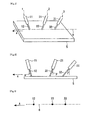
Fig. 1 is a perspective view schematically showing an example in which a steel plate is welded by applying a submerged welding method of the present invention, andFig. 2 is a side view schematically showing the example inFig. 1. Fig. 3 is a plan view showing a tip position of each wire on a surface of the steel plate shown inFig. 1 .Fig. 4 is a sectional view schematically showing an example of a groove shape to which the present invention is applied, andFig. 5 is a sectional view schematically showing an example of a steel plate weld joint having the groove shown inFig. 4 . - First, a submerged arc welding method of the present invention is described with reference to
Figs. 1 to 3. Figs. 1 to 3 show an example using three electrodes, but the present invention relates to a submerged arc welding method using three or more electrodes, and is not limited to use of three electrodes. - As shown in
Fig. 1 , when three electrodes are used, an electrode at the head in a welding direction shown by arrow A is referred to as a "first electrode 1", and a locus of a moving tip position of awire 12 of the first electrode 1 on a surface of asteel plate 5 is referred to as a "weld line 6". An electrode second in the welding direction A is referred to as a "second electrode 2" and located behind the first electrode 1, and further athird electrode 3 is disposed behind the second electrode 2 on a line.Torches wires - First, the first electrode is described.
- A current density can be increased by thinning the
wire 12 of the first electrode 1, and a deep penetration can be achieved even with low welding heat input. Therefore thewire 12 has a wire diameter of 3.2 mm or less. However, with the wire diameter of less than 2.0 mm, thewire 12 is excessively thin, and thus a wire feeding rate is forced to be increased for securing a necessary amount of a weld metal, resulting in unstable wire feed speed and unstable welding. Therefore, thewire 12 of the first electrode 1 has a wire diameter in a range of 2.0 to 3.2 mm. - As described above, the current density of a current supplied to the
wire 12 of the first electrode 1 can be increased by using thewire 12 having a small wire diameter, but a sufficient depth of penetration cannot be obtained with a current density of less than 145 A/mm2. Therefore, the current density of thewire 12 of the first electrode 1 is 145 A/mm2 or more. Also, with the excessively high current density of thewire 12 of the first electrode 1, a wire feeding rate is forced to be increased, resulting in unstable welding. Therefore, the current density is preferably 310 A/mm2 or less. - The current supplied to the
wire 12 of the first electrode 1 is preferably a direct current in order to further increase the depth of penetration. - Further, as shown in
Fig. 2 , thewire 12 of the first electrode 1 is preferably inclined so that the tip of thewire 12 is located behind (that is, the second electrode side) thetorch 11 in the welding direction A. An angle a (referred to as a "sweep-back angle" hereinafter) formed by thewire 12 and a vertical line is preferably 15° or less because the effect of increasing the depth of penetration is significantly exhibited. In addition, thewire 12 of the first electrode 1 may be disposed vertically (sweep-back angle α = 0°). - Next, the second electrode is described.
- As shown in
Fig. 3 , the second electrode 2 is disposed so that thetip position 23 of thewire 22 on a surface of a steel plate is arranged on thewelding line 6. When thewire 22 has an excessively small wire diameter, a weld reinforcement height tends to be increased, and thus the wire diameter of thewire 22 is preferably 3.2 mm or more. On the other hand, when thewire 22 has an excessively large wire diameter, slag inclusion easily occurs, and thus the wire diameter of thewire 22 is preferably 4.0 mm or less. - Also, a current to be supplied to the
wire 22 is preferably an alternating current in order to prevent the occurrence of arc interference with the other electrodes. - Further, as shown in
Fig. 2 , thewire 22 of the second electrode 2 is preferably inclined so that the tip of thewire 22 is located ahead of (that is, the first electrode side) thetorch 21 in the welding direction A. An angle P (referred to as an "angle of advance" hereinafter) formed by thewire 22 and a vertical line is preferably 5° or more because the effect of widening a bead width is significantly exhibited. With the excessively large angle of advance, the torch is forced to be significantly lengthened, and thus the angle of advance of the second electrode 2 is 25° or less in view of limitation of equipment. - Next, the third electrode is described.
- As shown in
Fig. 3 , thethird electrode 3 is disposed so that thetip position 33 of thewire 32 on a surface of a steel plate is arranged on thewelding line 6. When thewire 32 has an excessively small wire diameter, a weld reinforcement height tends to be increased, and thus the wire diameter of thewire 32 is preferably 3.2 mm or more. On the other hand, when thewire 32 has an excessively large wire diameter, an amount of deposit metal of the wire is decreased, and thus the wire diameter of thewire 32 is preferably 4.0 mm or less. - Also, a current to be supplied to the
wire 32 is preferably an alternating current in order to prevent the occurrence of arc interference with the other electrodes. - As shown in
Fig. 2 , thewire 32 of thethird electrode 3 is preferably inclined so that the tip of thewire 32 is located ahead of (that is, on the first electrode side) thetorch 31 in the welding direction A. An angle y of advance is preferably 20° or more because the effect of widening a bead width is significantly exhibited. With the excessively large angle of advance, the torch is forced to be significantly lengthened, and thus in welding with four or more electrodes, the angle of advance of thethird electrode 3 is 30° or less in view of limitation of equipment. - Although an example using the three electrodes is described above, the number of electrodes used in the present invention is not limited to 3, and the present invention can be applied to submerged arc welding using three or more electrodes. In particular, when 3 to 5 electrodes are used, a significant effect can be obtained. Use of 6 or more electrodes is undesired because of deterioration in toughness of a welded heat affected zone due to excessive welding heat input.
- When fourth and subsequent electrodes are arranged behind the
third electrode 3, the electrodes are disposed in a line so that the tip positions of wires on a surface of a steel plate are arranged on thewelding line 6. The wire diameters and angles of advance of the wires used are the same as those in the third electrode, and an alternating current is preferably supplied. Next, a groove shape to which the present invention is applied, and the shape of a weld joint produced by the groove shape are described with reference toFigs. 4 and 5 . - As shown in
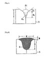
Fig. 4 , a groove shape to which the present invention is applied is a two-step groove shape including combination of two types of groove angles, and a groove angle on the bottom side (referred to as a "groove angle of a bottom layer" hereinafter) of asteel plate 5 is θB, and a groove angle on the surface side (referred to as a "groove angle of a surface layer" hereinafter) of thesteel plate 5 is θT. - With the groove angle θB of a bottom layer of less than 40°, slag inclusion easily occurs during welding, and the weld enforcement height is increased, while with the groove angle θB of a bottom layer over 70°, a groove sectional area is increased, and a required amount of deposit metal of the wire is increased, thereby causing the need to set the welding heat input high. Therefore, the groove angle θB of a bottom layer is preferably in a range of 40° to 70°.
- With the groove angle θT of a surface layer of less than 90°, the effect of widening a bead width is small, while with the groove angle θT of a surface layer over 120°, a groove width is excessively increased, and thus undercut easily occurs. Therefore, the groove angle θT of a surface layer is preferably in a range of 90° to 120°.
- In order to achieve a deep depth of penetration and a wide bead width and decrease a weld reinforcement height by applying the submerged arc welding method of the present invention to the two step groove including the combination of the groove angle θB of a bottom layer and the groove angle θT of a surface layer, it is necessary to satisfy that θB < θT.
- Also, as shown in
Fig. 4 , when HB < HT is satisfied, where HB is a depth of a portion at the groove angle θB of a bottom layer (hereinafter referred to as a "groove depth of a bottom layer"), and HT is a depth of a portion at the groove angle θT of a surface layer (hereinafter referred to as a "groove depth of a surface layer"), a groove sectional area is increased, and a required amount of deposit metal of the wire is increased, thereby causing the need to set the welding heat input high. Therefore, the groove depth HB of a bottom layer and the groove depth HT of a surface layer preferably satisfy HB ≥ HT. - As described above, according to the present invention, it is possible to decrease the welding heat input and secure depth of penetration D, decrease weld reinforcement height M, and achieve wide bead width W as shown in
Fig. 5 . - Also, the present invention can be applied to one-side welding and both-side welding. Particularly in application to welding of a plate having a thickness exceeding 30 mm, it is possible to achieve a deep depth of penetration and a wide bead width and decrease welding heat input, and thus the present invention is effective in improving toughness of a welded heat affected zone and preventing undercut.
- Further, a solid wire is generally used as a welding wire for submerged arc welding, but not only the solid wire but also a metal cored wire can be applied to the present invention.
- After a two-step groove was formed in the
steel plate 5 having a thickness T of 31.8 mm as shown inFig. 4 , a weld joint shown inFig. 5 was formed in one pass of submerged arc welding using 3 to 5 electrodes. Table 1 shows groove shapes, Table 2 shows welding conditions, Table 3 shows arrangements of electrodes, and Table 4 shows setting of welding currents.[Table 1] Number Thickness (mm) Bottom layer Surface layer Groove width (mm) Groove cross-sectional area (mm) Groove angle θB (°) Groove depth HB (mm) Groove angle θT (°) Groove depth HT (mm) 1 31.8 50 8.0 100 5.0 19.4 96.9 2 31.8 40 6.5 100 6.5 20.2 96.5 3 31.8 70 10.0 100 3.0 21.2 122.8 4 31.8 50 8.0 100 5.0 19.4 96.9 5 31.8 50 8.0 100 5.0 19.4 96.9 6 31.8 70 13.0 - - 18.2 118.3 7 31.8 36 6.5 100 6.5 19.7 91.5 8 31.8 80 8.0 100 5.0 25.3 150.6 9 31.8 70 10.0 130 3.0 26.9 131.3 10 31.8 50 5.0 100 8.0 23.7 125.2 11 31.8 50 8.0 100 5.0 19.4 96.9 12 31.8 50 8.0 100 5.0 19.4 96.9 13 31.8 50 8.0 100 5.0 19.4 96.9 14 31.8 50 8.0 100 5.0 19.4 96.9 [Table 2] Number #1* #2* #3* #4* #5* Welding speed (cm/min) Welding heat input (kJ/mm) Current (A) Voltage (V) Wire diameter (mm) Current (A) Voltage (V) Wire diameter (mm) Current (A) Voltage (V) Wire diameter (mm) Current (A) Voltage (V) Wire diameter (mm) Current (A) Voltage (V) Wire diameter (mm) 1 1200 34 2.4 1080 38 4.0 840 42 4.0 720 42 4.0 - - - 140 6.3 2 950 32 2.0 850 38 4.0 660 42 4.0 570 42 4.0 - - - 109 6.3 3 1280 35 3.2 860 36 3.2 850 44 4.0 750 44 4.0 - - - 110 8.0 4 800 32 1.6 720 40 3.2 560 45 3.2 480 45 3.2 - - - 97 6.3 5 1400 35 4.0 1100 36 4.0 950 42 4.0 800 42 4.0 - - - 155 6.3 6 1200 34 2.4 1080 38 4.0 840 42 4.0 720 42 4.0 - - - 140 6.3 7 1200 34 2.4 1080 38 4.0 760 48 4.0 650 48 4.0 - - - 150 6.0 8 1400 32 3.2 980 42 4.0 820 44 4.0 700 44 4.0 - - - 145 6.3 9 1250 35 2.4 1000 42 3.2 850 42 3.2 700 42 3.2 - - - 143 6.3 10 1300 33 2.4 1120 36 4.0 900 42 4.0 790 44 4.0 - - - 150 6.3 11 1200 34 2.4 1000 40 3.2 840 42 4.0 730 42 4.0 - - - 140 6.3 12 1200 35 2.4 850 45 2.4 750 45 3.2 700 40 3.2 - - - 135 6.3 13 1250 34 2.4 900 36 4.0 850 42 4.0 - - - - - - 105 6.3 14 1250 34 2.4 900 36 4.0 850 42 4.0 750 42 4.0 680 44 4.0 165 6.3 * #1 to #5 represent first electrode to fifth electrode, respectively. [Table 3] Number Distance between electrodes (mm) * Distance between base metal and tip (mm) Electrode angle (°) ** #1 to #2 #" to #3 #3 to #4 #4 to #5 #1 #2 #3 #4 #5 #1 #2 #3 #4 #5 1 16 12 12 - 30 30 30 30 - 0 13 25 40 - 2 22 14 12 - 30 30 35 35 - -5 12 24 36 - 3 18 13 13 - 25 25 30 30 - 0 15 30 45 - 4 30 16 16 - 30 30 32 32 - 0 13 25 36 - 5 17 13 15 - 25 30 32 32 - 0 12 24 36 - 6 16 12 12 - 30 30 30 30 - 0 13 25 40 - 7 20 14 14 - 30 30 35 35 - 0 12 24 36 - 8 15 10 10 - 30 32 35 35 - 0 12 24 36 - 9 25 15 15 - 30 30 35 35 - -5 5 30 45 - 10 20 14 14 - 28 30 32 32 - 0 12 24 36 - 11 27 18 10 - 30 30 35 35 - 0 12 24 36 - 12 30 20 10 - 30 35 36 36 - -5 5 24 44 - 13 20 15 - - 30 32 32 - - 0 12 24 - - 14 16 12 10 10 30 30 35 35 35 -8 0 8 25 45 * #1 to #5 represent first electrode to fifth electrode, respectively.
** A positive electrode angle represents an angle of advance, and a negative electrode angle represents a sweep-back angle.[Table 4] Number Current density of first electrode (A/mm2) Type of power supoly * #1 #2 #3 #4 #5 1 265 DC AC AC AC - 2 302 DC AC AC AC - 3 159 DC AC AC AC - 4 398 DC AC AC AC - 5 111 DC AC AC AC - 6 265 DC AC AC AC - 7 265 DC AC AC AC - 8 174 DC AC AC AC - 9 276 DC AC AC AC - 10 287 DC AC AC AC - 11 265 AC AC AC AC - 12 265 DC AC AC AC - 13 276 DC AC AC - - 14 276 DC AC AC AC AC * #1 to #5 represent first electrode to fifth electrode, respectively. - The bead appearances of the resultant weld joints were visually observed, and further cross-sections of bead constant regions were observed to measure depth of penetration D (mm), bead width W (mm), and weld reinforcement height M (mm). The results are shown in Table 5.
[Table 5] Number Depth of penetration (mm) Bead width (mm) Weld reinforcement height (mm) Defect Bead appearance Remarks 1 19.2 25.3 1.6 No Beautiful Invention Example 2 19.8 24.9 2.5 No Beautiful Invention Example 3 22.2 30.6 1.0 No Beautiful Invention Example 4 16.9 25.2 3.2 No Beautiful Comparative Example 5 16.4 28.3 1.1 No Beautiful Comparative Example 6 20.8 22.5 2.6 No Beautiful Comparative Example 7 18.4 24.3 3.5 Slag inclusion Beautiful Intention Example 8 21.5 25.0 2.1 No Undercut Invention Example 9 20.7 26.4 2.5 No Undercut Invention Example 10 18.8 24.6 1.8 No Undercut Invention Example 11 18.6 26.1 1.9 No Beautiful Invention Example 12 19.4 24.6 2.7 No Beautiful Invention Example 13 21.5 26.1 1.2 No Beautiful Invention Example 14 18.4 24.4 1.4 No Beautiful Invention Example - Table 5 indicates that in an invention example according to the present invention, a deep depth of penetration (18.4 to 22.2 mm) and a wide bead width (24.4 to 30.6 mm) can be achieved with low heat input.
- In particular, in Numbers 1 to 3, 13, and 14, the bead appearance is good without defects, and the weld reinforcement height is low (1.0 to 2.5 mm).
- On the other hand, in Number 4 of a comparative example, the depth of penetration and the bead width are satisfactory, but a large current cannot be supplied because of the first electrode having a wire diameter of 1.6 mm, thereby failing to achieve a deep depth of penetration. In
Number 5, a high current density cannot be supplied because of the first electrode having a wire diameter of 4.0 mm, thereby failing to achieve a deep depth of penetration. InNumber 6, a V-groove, not a two-step groove, is used, and thus a wide bead width cannot be achieved. -
- 1
- first electrode
- 11
- torch of first electrode
- 12
- wire of first electrode
- 13
- tip position of wire of first electrode
- 2
- second electrode
- 21
- torch of second electrode
- 22
- wire of second electrode
- 23
- tip position of wire of second electrode
- 3
- third electrode
- 31
- torch of third electrode
- 32
- wire of third electrode
- 33
- tip position of wire of third electrode
- 5
- steel plate
- 6
- welding line
Claims (6)
- A submerged arc welding method for a steel plate using three or more electrodes, wherein a first electrode at the head in a welding direction has a wire diameter of 2.0 to 3.2 mm and a current density of 145 A/mm2 or more, second and subsequent electrodes are arranged behind the first electrode in a line, and a groove formed in a steel plate to be welded has a two-step groove shape satisfying θB < θT where θB is a groove angle of a bottom layer, and θT is a groove angle of a surface layer.
- The submerged arc welding method according to Claim 1, wherein the groove angle θB of a bottom layer is 40 to 70°.
- The submerged arc welding method according to Claim 1 or 2, wherein the groove angle θT of a surface layer is 120° or less.
- The submerged arc welding method according to any one of Claims 1 to 3, wherein the groove satisfies HB ≥ HT, where HB is a depth of a portion at the groove angle θB of a bottom layer, and HT is a depth of a portion at the groove angle θT of a surface layer.
- The submerged arc welding according to any one of Claims 1 to 4, wherein a direct current is supplied to the first electrode, and an alternating current is supplied to the second and subsequent electrodes.
- The submerged arc welding method according to any one of Claims 1 to 5, wherein the second and subsequent electrodes have a wire diameter of 3.2 mm or more.
Applications Claiming Priority (2)
| Application Number | Priority Date | Filing Date | Title |
|---|---|---|---|
| JP2011260265 | 2011-11-29 | ||
| PCT/JP2012/007610 WO2013080523A1 (en) | 2011-11-29 | 2012-11-28 | Submerged arc welding method for steel sheets |
Publications (3)
| Publication Number | Publication Date |
|---|---|
| EP2786830A1 true EP2786830A1 (en) | 2014-10-08 |
| EP2786830A4 EP2786830A4 (en) | 2016-04-20 |
| EP2786830B1 EP2786830B1 (en) | 2018-03-28 |
Family
ID=48535017
Family Applications (1)
| Application Number | Title | Priority Date | Filing Date |
|---|---|---|---|
| EP12853275.1A Active EP2786830B1 (en) | 2011-11-29 | 2012-11-28 | Submerged arc welding method for steel sheets |
Country Status (7)
| Country | Link |
|---|---|
| US (1) | US20140346149A1 (en) |
| EP (1) | EP2786830B1 (en) |
| JP (1) | JP5772977B2 (en) |
| KR (3) | KR20170018972A (en) |
| CN (2) | CN108788409A (en) |
| RU (1) | RU2592335C2 (en) |
| WO (1) | WO2013080523A1 (en) |
Cited By (1)
| Publication number | Priority date | Publication date | Assignee | Title |
|---|---|---|---|---|
| CN105880952A (en) * | 2016-06-03 | 2016-08-24 | 合肥紫金钢管股份有限公司 | Production process of longitudinal submerged arc welded pipe for oil and gas transmission |
Families Citing this family (13)
| Publication number | Priority date | Publication date | Assignee | Title |
|---|---|---|---|---|
| JP6211431B2 (en) * | 2014-02-12 | 2017-10-11 | 株式会社神戸製鋼所 | Multi-electrode single-sided submerged arc welding method, welded product manufacturing method |
| JP2015150572A (en) * | 2014-02-12 | 2015-08-24 | 株式会社神戸製鋼所 | Method of welding multi-electrode single-sided submerged arc, method of manufacturing weldment |
| CN104475921B (en) * | 2014-12-10 | 2016-04-20 | 青岛北海船舶重工有限责任公司 | Expand welding layout structure and the process of three FCB method welding scopes |
| JP6383319B2 (en) * | 2015-03-31 | 2018-08-29 | 株式会社神戸製鋼所 | Multi-electrode single-sided single layer submerged arc welding method |
| US11453079B2 (en) * | 2016-02-19 | 2022-09-27 | Jfe Steel Corporation | Multi-electrode submerged arc welding method |
| CN107262883A (en) * | 2017-08-02 | 2017-10-20 | 中国石油天然气集团公司 | A kind of multi-wire submerged-arc welding process of X70 heavy walls steel pipes with straight |
| CN109079287B (en) * | 2018-09-14 | 2020-09-29 | 大连理工大学 | Three-wire gas-shielded indirect arc welding method and device and application thereof |
| CN113732552B (en) * | 2020-05-27 | 2022-09-16 | 宝山钢铁股份有限公司 | Low-carbon micro-alloy steel high-heat input weldability evaluation method based on multi-wire submerged arc welding |
| CN112296494B (en) * | 2020-10-23 | 2022-05-10 | 中船黄埔文冲船舶有限公司 | Welding flux copper gasket method submerged-arc welding method for jointed boards with different thicknesses |
| CN114762907B (en) * | 2021-01-13 | 2024-05-14 | 宝山钢铁股份有限公司 | Double-sided submerged arc welding method for thick-wall high-strength steel in dynamic load occasion |
| CN113579430B (en) * | 2021-07-22 | 2022-11-18 | 武汉钢铁有限公司 | Narrow-slit submerged arc welding method suitable for medium plate wear-resistant steel |
| JP7485250B1 (en) | 2023-02-24 | 2024-05-16 | Jfeスチール株式会社 | One-sided submerged arc welding method and method for manufacturing welded joint |
| WO2024176507A1 (en) * | 2023-02-24 | 2024-08-29 | Jfeスチール株式会社 | One-sided submerged arc welding method and weld joint |
Family Cites Families (19)
| Publication number | Priority date | Publication date | Assignee | Title |
|---|---|---|---|---|
| JPS5811313B2 (en) * | 1976-08-24 | 1983-03-02 | 新日本製鐵株式会社 | High efficiency multi-electrode submerged arc welding method |
| US5004884A (en) * | 1988-12-28 | 1991-04-02 | Kawasaki Steel Corporation | Method of submerged arc welding a thick steel plate with large heat input and submerged arc welding flux |
| JPH0673757B2 (en) * | 1988-12-28 | 1994-09-21 | 川崎製鉄株式会社 | Large heat input latent arc welding method for thick steel plate |
| US5140140A (en) * | 1990-11-15 | 1992-08-18 | Pollack Alex J | Method and apparatus of submerged arc welding with electrodes in tandem |
| RU2080224C1 (en) * | 1992-11-04 | 1997-05-27 | Институт Электросварки Им.Е.О.Патона | Four-arc welding method |
| JP3463333B2 (en) * | 1994-01-14 | 2003-11-05 | Jfeスチール株式会社 | Large heat input multilayer submerged arc welding method for thick steel plate |
| JP3503191B2 (en) * | 1994-06-14 | 2004-03-02 | Jfeスチール株式会社 | Large heat input multi-layer submerged arc welding method for thick steel plate |
| JPH10109171A (en) | 1996-10-02 | 1998-04-28 | Ishikawajima Harima Heavy Ind Co Ltd | High current density submerged arc welding method |
| JP3304815B2 (en) * | 1997-04-08 | 2002-07-22 | 住友金属工業株式会社 | Manufacturing method of thick wall large diameter welded steel pipe |
| JPH11138266A (en) | 1997-11-10 | 1999-05-25 | Ishikawajima Harima Heavy Ind Co Ltd | Tandem submerged arc welding method |
| JP3624727B2 (en) * | 1997-12-24 | 2005-03-02 | Jfeスチール株式会社 | Multi-layer submerged arc welding method for extra-thick steel plates |
| JP3801186B2 (en) * | 1997-12-24 | 2006-07-26 | Jfeスチール株式会社 | Ultra-thick welded material by multilayer submerged arc welding |
| JP2001121266A (en) * | 1999-10-27 | 2001-05-08 | Kawasaki Steel Corp | Method for submerged arc welding |
| JP5283306B2 (en) * | 2005-03-28 | 2013-09-04 | Jfeスチール株式会社 | Submerged arc welding method for steel |
| RU2293001C1 (en) * | 2005-05-11 | 2007-02-10 | ОАО "Челябинский трубопрокатный завод" | Method of submerged multiarc welding |
| KR100910495B1 (en) * | 2007-12-26 | 2009-07-31 | 주식회사 포스코 | Welding method of steel plate with excellent low temperature toughness of welded joint |
| JP5239900B2 (en) | 2009-01-27 | 2013-07-17 | Jfeスチール株式会社 | Multi-electrode submerged arc welding method for steel |
| EP2436472B1 (en) * | 2009-05-27 | 2023-02-01 | JFE Steel Corporation | Submerged arc welding method for steel plate |
| RU2410215C1 (en) * | 2010-01-19 | 2011-01-27 | Закрытое акционерное общество "ЭЛЕКТРИК-МИКС" | Procedure for automatic electric-arc hidden pad-weld of external or internal surfaces of rotary bodies |
-
2012
- 2012-11-28 WO PCT/JP2012/007610 patent/WO2013080523A1/en active Application Filing
- 2012-11-28 CN CN201810595184.9A patent/CN108788409A/en active Pending
- 2012-11-28 JP JP2013546994A patent/JP5772977B2/en active Active
- 2012-11-28 KR KR1020177003694A patent/KR20170018972A/en active Search and Examination
- 2012-11-28 RU RU2014125804/02A patent/RU2592335C2/en active
- 2012-11-28 KR KR1020197011018A patent/KR20190043638A/en not_active IP Right Cessation
- 2012-11-28 US US14/359,691 patent/US20140346149A1/en not_active Abandoned
- 2012-11-28 KR KR1020147014225A patent/KR20140094579A/en active Application Filing
- 2012-11-28 EP EP12853275.1A patent/EP2786830B1/en active Active
- 2012-11-28 CN CN201280058087.7A patent/CN103958109A/en active Pending
Cited By (1)
| Publication number | Priority date | Publication date | Assignee | Title |
|---|---|---|---|---|
| CN105880952A (en) * | 2016-06-03 | 2016-08-24 | 合肥紫金钢管股份有限公司 | Production process of longitudinal submerged arc welded pipe for oil and gas transmission |
Also Published As
| Publication number | Publication date |
|---|---|
| JPWO2013080523A1 (en) | 2015-04-27 |
| RU2592335C2 (en) | 2016-07-20 |
| US20140346149A1 (en) | 2014-11-27 |
| RU2014125804A (en) | 2015-12-27 |
| KR20190043638A (en) | 2019-04-26 |
| CN103958109A (en) | 2014-07-30 |
| KR20170018972A (en) | 2017-02-20 |
| WO2013080523A1 (en) | 2013-06-06 |
| JP5772977B2 (en) | 2015-09-02 |
| EP2786830A4 (en) | 2016-04-20 |
| CN108788409A (en) | 2018-11-13 |
| KR20140094579A (en) | 2014-07-30 |
| EP2786830B1 (en) | 2018-03-28 |
Similar Documents
| Publication | Publication Date | Title |
|---|---|---|
| EP2786830B1 (en) | Submerged arc welding method for steel sheets | |
| JP2015223605A (en) | Narrow groove gas-shield arc-welding method | |
| JP6119940B1 (en) | Vertical narrow groove gas shielded arc welding method | |
| EP2786829B1 (en) | Submerged arc welding method for steel sheets | |
| CN104708179B (en) | Application of Double TIG Welding Method in Implementing Thick Plate Welding | |
| JP5239900B2 (en) | Multi-electrode submerged arc welding method for steel | |
| CN103273177A (en) | Double-TIG (tungsten inert gas) welding system for thick plates and welding method implemented by double-TIG welding system | |
| EP3417979A1 (en) | Multi-electrode submerged arc welding method | |
| JP5895423B2 (en) | Multi-electrode submerged arc welding method for steel sheet | |
| KR102362487B1 (en) | Welding system | |
| CN107717230A (en) | A kind of lateral CMT complex welding methods of laser | |
| EP4501513A1 (en) | Narrow gap gas-shielded arc welding method and welding apparatus for narrow gap gas-shielded arc welding | |
| JP5895477B2 (en) | Multi-electrode submerged arc welding method for steel sheet | |
| JP6607677B2 (en) | Four-electrode single-sided single-layer submerged arc welding method | |
| JP7323781B2 (en) | Multi-electrode submerged arc welding method | |
| JP2017213569A (en) | Submerged arc welding method | |
| EP3132879B1 (en) | Tack welding method in production process for large-diameter welded steel pipe or tube | |
| WO2023189026A1 (en) | Narrow gap gas-shielded arc welding method and welding apparatus for narrow gap gas-shielded arc welding | |
| JP2023152736A (en) | Narrow groove gas-shield arc-welding method for thick steel plates | |
| JPWO2017094578A1 (en) | Vertical narrow groove gas shielded arc welding method | |
| JP2007038288A (en) | Gougingless complete penetration welding method using high current pulse mag |
Legal Events
| Date | Code | Title | Description |
|---|---|---|---|
| PUAI | Public reference made under article 153(3) epc to a published international application that has entered the european phase |
Free format text: ORIGINAL CODE: 0009012 |
|
| 17P | Request for examination filed |
Effective date: 20140623 |
|
| AK | Designated contracting states |
Kind code of ref document: A1 Designated state(s): AL AT BE BG CH CY CZ DE DK EE ES FI FR GB GR HR HU IE IS IT LI LT LU LV MC MK MT NL NO PL PT RO RS SE SI SK SM TR |
|
| DAX | Request for extension of the european patent (deleted) | ||
| RA4 | Supplementary search report drawn up and despatched (corrected) |
Effective date: 20160317 |
|
| RIC1 | Information provided on ipc code assigned before grant |
Ipc: B23K 33/00 20060101ALI20160311BHEP Ipc: B23K 9/18 20060101AFI20160311BHEP |
|
| STAA | Information on the status of an ep patent application or granted ep patent |
Free format text: STATUS: EXAMINATION IS IN PROGRESS |
|
| 17Q | First examination report despatched |
Effective date: 20161222 |
|
| REG | Reference to a national code |
Ref country code: DE Ref legal event code: R079 Ref document number: 602012044593 Country of ref document: DE Free format text: PREVIOUS MAIN CLASS: B23K0009180000 Ipc: B23K0101060000 |
|
| GRAP | Despatch of communication of intention to grant a patent |
Free format text: ORIGINAL CODE: EPIDOSNIGR1 |
|
| STAA | Information on the status of an ep patent application or granted ep patent |
Free format text: STATUS: GRANT OF PATENT IS INTENDED |
|
| RIC1 | Information provided on ipc code assigned before grant |
Ipc: B23K 101/06 20060101AFI20170918BHEP Ipc: B23K 33/00 20060101ALI20170918BHEP Ipc: B23K 103/04 20060101ALI20170918BHEP Ipc: B23K 9/18 20060101ALI20170918BHEP |
|
| INTG | Intention to grant announced |
Effective date: 20171013 |
|
| GRAS | Grant fee paid |
Free format text: ORIGINAL CODE: EPIDOSNIGR3 |
|
| GRAA | (expected) grant |
Free format text: ORIGINAL CODE: 0009210 |
|
| STAA | Information on the status of an ep patent application or granted ep patent |
Free format text: STATUS: THE PATENT HAS BEEN GRANTED |
|
| AK | Designated contracting states |
Kind code of ref document: B1 Designated state(s): AL AT BE BG CH CY CZ DE DK EE ES FI FR GB GR HR HU IE IS IT LI LT LU LV MC MK MT NL NO PL PT RO RS SE SI SK SM TR |
|
| REG | Reference to a national code |
Ref country code: GB Ref legal event code: FG4D |
|
| REG | Reference to a national code |
Ref country code: CH Ref legal event code: EP |
|
| REG | Reference to a national code |
Ref country code: AT Ref legal event code: REF Ref document number: 982965 Country of ref document: AT Kind code of ref document: T Effective date: 20180415 |
|
| REG | Reference to a national code |
Ref country code: IE Ref legal event code: FG4D |
|
| REG | Reference to a national code |
Ref country code: DE Ref legal event code: R096 Ref document number: 602012044593 Country of ref document: DE |
|
| PG25 | Lapsed in a contracting state [announced via postgrant information from national office to epo] |
Ref country code: FI Free format text: LAPSE BECAUSE OF FAILURE TO SUBMIT A TRANSLATION OF THE DESCRIPTION OR TO PAY THE FEE WITHIN THE PRESCRIBED TIME-LIMIT Effective date: 20180328 Ref country code: LT Free format text: LAPSE BECAUSE OF FAILURE TO SUBMIT A TRANSLATION OF THE DESCRIPTION OR TO PAY THE FEE WITHIN THE PRESCRIBED TIME-LIMIT Effective date: 20180328 Ref country code: HR Free format text: LAPSE BECAUSE OF FAILURE TO SUBMIT A TRANSLATION OF THE DESCRIPTION OR TO PAY THE FEE WITHIN THE PRESCRIBED TIME-LIMIT Effective date: 20180328 Ref country code: NO Free format text: LAPSE BECAUSE OF FAILURE TO SUBMIT A TRANSLATION OF THE DESCRIPTION OR TO PAY THE FEE WITHIN THE PRESCRIBED TIME-LIMIT Effective date: 20180628 |
|
| REG | Reference to a national code |
Ref country code: NL Ref legal event code: MP Effective date: 20180328 |
|
| REG | Reference to a national code |
Ref country code: LT Ref legal event code: MG4D |
|
| PG25 | Lapsed in a contracting state [announced via postgrant information from national office to epo] |
Ref country code: GR Free format text: LAPSE BECAUSE OF FAILURE TO SUBMIT A TRANSLATION OF THE DESCRIPTION OR TO PAY THE FEE WITHIN THE PRESCRIBED TIME-LIMIT Effective date: 20180629 Ref country code: BG Free format text: LAPSE BECAUSE OF FAILURE TO SUBMIT A TRANSLATION OF THE DESCRIPTION OR TO PAY THE FEE WITHIN THE PRESCRIBED TIME-LIMIT Effective date: 20180628 Ref country code: RS Free format text: LAPSE BECAUSE OF FAILURE TO SUBMIT A TRANSLATION OF THE DESCRIPTION OR TO PAY THE FEE WITHIN THE PRESCRIBED TIME-LIMIT Effective date: 20180328 Ref country code: SE Free format text: LAPSE BECAUSE OF FAILURE TO SUBMIT A TRANSLATION OF THE DESCRIPTION OR TO PAY THE FEE WITHIN THE PRESCRIBED TIME-LIMIT Effective date: 20180328 Ref country code: LV Free format text: LAPSE BECAUSE OF FAILURE TO SUBMIT A TRANSLATION OF THE DESCRIPTION OR TO PAY THE FEE WITHIN THE PRESCRIBED TIME-LIMIT Effective date: 20180328 |
|
| PG25 | Lapsed in a contracting state [announced via postgrant information from national office to epo] |
Ref country code: PL Free format text: LAPSE BECAUSE OF FAILURE TO SUBMIT A TRANSLATION OF THE DESCRIPTION OR TO PAY THE FEE WITHIN THE PRESCRIBED TIME-LIMIT Effective date: 20180328 Ref country code: NL Free format text: LAPSE BECAUSE OF FAILURE TO SUBMIT A TRANSLATION OF THE DESCRIPTION OR TO PAY THE FEE WITHIN THE PRESCRIBED TIME-LIMIT Effective date: 20180328 Ref country code: EE Free format text: LAPSE BECAUSE OF FAILURE TO SUBMIT A TRANSLATION OF THE DESCRIPTION OR TO PAY THE FEE WITHIN THE PRESCRIBED TIME-LIMIT Effective date: 20180328 Ref country code: ES Free format text: LAPSE BECAUSE OF FAILURE TO SUBMIT A TRANSLATION OF THE DESCRIPTION OR TO PAY THE FEE WITHIN THE PRESCRIBED TIME-LIMIT Effective date: 20180328 Ref country code: RO Free format text: LAPSE BECAUSE OF FAILURE TO SUBMIT A TRANSLATION OF THE DESCRIPTION OR TO PAY THE FEE WITHIN THE PRESCRIBED TIME-LIMIT Effective date: 20180328 Ref country code: AL Free format text: LAPSE BECAUSE OF FAILURE TO SUBMIT A TRANSLATION OF THE DESCRIPTION OR TO PAY THE FEE WITHIN THE PRESCRIBED TIME-LIMIT Effective date: 20180328 |
|
| PG25 | Lapsed in a contracting state [announced via postgrant information from national office to epo] |
Ref country code: CZ Free format text: LAPSE BECAUSE OF FAILURE TO SUBMIT A TRANSLATION OF THE DESCRIPTION OR TO PAY THE FEE WITHIN THE PRESCRIBED TIME-LIMIT Effective date: 20180328 Ref country code: SM Free format text: LAPSE BECAUSE OF FAILURE TO SUBMIT A TRANSLATION OF THE DESCRIPTION OR TO PAY THE FEE WITHIN THE PRESCRIBED TIME-LIMIT Effective date: 20180328 Ref country code: SK Free format text: LAPSE BECAUSE OF FAILURE TO SUBMIT A TRANSLATION OF THE DESCRIPTION OR TO PAY THE FEE WITHIN THE PRESCRIBED TIME-LIMIT Effective date: 20180328 |
|
| REG | Reference to a national code |
Ref country code: AT Ref legal event code: MK05 Ref document number: 982965 Country of ref document: AT Kind code of ref document: T Effective date: 20180328 |
|
| PG25 | Lapsed in a contracting state [announced via postgrant information from national office to epo] |
Ref country code: PT Free format text: LAPSE BECAUSE OF FAILURE TO SUBMIT A TRANSLATION OF THE DESCRIPTION OR TO PAY THE FEE WITHIN THE PRESCRIBED TIME-LIMIT Effective date: 20180730 |
|
| REG | Reference to a national code |
Ref country code: DE Ref legal event code: R097 Ref document number: 602012044593 Country of ref document: DE |
|
| PG25 | Lapsed in a contracting state [announced via postgrant information from national office to epo] |
Ref country code: DK Free format text: LAPSE BECAUSE OF FAILURE TO SUBMIT A TRANSLATION OF THE DESCRIPTION OR TO PAY THE FEE WITHIN THE PRESCRIBED TIME-LIMIT Effective date: 20180328 Ref country code: AT Free format text: LAPSE BECAUSE OF FAILURE TO SUBMIT A TRANSLATION OF THE DESCRIPTION OR TO PAY THE FEE WITHIN THE PRESCRIBED TIME-LIMIT Effective date: 20180328 |
|
| PLBE | No opposition filed within time limit |
Free format text: ORIGINAL CODE: 0009261 |
|
| STAA | Information on the status of an ep patent application or granted ep patent |
Free format text: STATUS: NO OPPOSITION FILED WITHIN TIME LIMIT |
|
| 26N | No opposition filed |
Effective date: 20190103 |
|
| PG25 | Lapsed in a contracting state [announced via postgrant information from national office to epo] |
Ref country code: SI Free format text: LAPSE BECAUSE OF FAILURE TO SUBMIT A TRANSLATION OF THE DESCRIPTION OR TO PAY THE FEE WITHIN THE PRESCRIBED TIME-LIMIT Effective date: 20180328 |
|
| REG | Reference to a national code |
Ref country code: CH Ref legal event code: PL |
|
| PG25 | Lapsed in a contracting state [announced via postgrant information from national office to epo] |
Ref country code: LU Free format text: LAPSE BECAUSE OF NON-PAYMENT OF DUE FEES Effective date: 20181128 Ref country code: MC Free format text: LAPSE BECAUSE OF FAILURE TO SUBMIT A TRANSLATION OF THE DESCRIPTION OR TO PAY THE FEE WITHIN THE PRESCRIBED TIME-LIMIT Effective date: 20180328 |
|
| REG | Reference to a national code |
Ref country code: BE Ref legal event code: MM Effective date: 20181130 |
|
| REG | Reference to a national code |
Ref country code: IE Ref legal event code: MM4A |
|
| PG25 | Lapsed in a contracting state [announced via postgrant information from national office to epo] |
Ref country code: LI Free format text: LAPSE BECAUSE OF NON-PAYMENT OF DUE FEES Effective date: 20181130 Ref country code: CH Free format text: LAPSE BECAUSE OF NON-PAYMENT OF DUE FEES Effective date: 20181130 |
|
| PG25 | Lapsed in a contracting state [announced via postgrant information from national office to epo] |
Ref country code: IE Free format text: LAPSE BECAUSE OF NON-PAYMENT OF DUE FEES Effective date: 20181128 |
|
| PG25 | Lapsed in a contracting state [announced via postgrant information from national office to epo] |
Ref country code: BE Free format text: LAPSE BECAUSE OF NON-PAYMENT OF DUE FEES Effective date: 20181130 |
|
| PG25 | Lapsed in a contracting state [announced via postgrant information from national office to epo] |
Ref country code: MT Free format text: LAPSE BECAUSE OF NON-PAYMENT OF DUE FEES Effective date: 20181128 |
|
| PG25 | Lapsed in a contracting state [announced via postgrant information from national office to epo] |
Ref country code: TR Free format text: LAPSE BECAUSE OF FAILURE TO SUBMIT A TRANSLATION OF THE DESCRIPTION OR TO PAY THE FEE WITHIN THE PRESCRIBED TIME-LIMIT Effective date: 20180328 |
|
| PG25 | Lapsed in a contracting state [announced via postgrant information from national office to epo] |
Ref country code: CY Free format text: LAPSE BECAUSE OF FAILURE TO SUBMIT A TRANSLATION OF THE DESCRIPTION OR TO PAY THE FEE WITHIN THE PRESCRIBED TIME-LIMIT Effective date: 20180328 Ref country code: HU Free format text: LAPSE BECAUSE OF FAILURE TO SUBMIT A TRANSLATION OF THE DESCRIPTION OR TO PAY THE FEE WITHIN THE PRESCRIBED TIME-LIMIT; INVALID AB INITIO Effective date: 20121128 Ref country code: MK Free format text: LAPSE BECAUSE OF NON-PAYMENT OF DUE FEES Effective date: 20180328 |
|
| PG25 | Lapsed in a contracting state [announced via postgrant information from national office to epo] |
Ref country code: IS Free format text: LAPSE BECAUSE OF FAILURE TO SUBMIT A TRANSLATION OF THE DESCRIPTION OR TO PAY THE FEE WITHIN THE PRESCRIBED TIME-LIMIT Effective date: 20180728 |
|
| REG | Reference to a national code |
Ref country code: DE Ref legal event code: R082 Ref document number: 602012044593 Country of ref document: DE Representative=s name: HL KEMPNER PATENTANWAELTE, SOLICITORS (ENGLAND, DE Ref country code: DE Ref legal event code: R082 Ref document number: 602012044593 Country of ref document: DE Representative=s name: HL KEMPNER PATENTANWALT, RECHTSANWALT, SOLICIT, DE |
|
| PGFP | Annual fee paid to national office [announced via postgrant information from national office to epo] |
Ref country code: DE Payment date: 20241001 Year of fee payment: 13 |
|
| PGFP | Annual fee paid to national office [announced via postgrant information from national office to epo] |
Ref country code: GB Payment date: 20241002 Year of fee payment: 13 |
|
| PGFP | Annual fee paid to national office [announced via postgrant information from national office to epo] |
Ref country code: FR Payment date: 20241001 Year of fee payment: 13 |
|
| PGFP | Annual fee paid to national office [announced via postgrant information from national office to epo] |
Ref country code: IT Payment date: 20241010 Year of fee payment: 13 |