EP2786217B1 - Coolant system for machine tools - Google Patents
Coolant system for machine tools Download PDFInfo
- Publication number
- EP2786217B1 EP2786217B1 EP12748040.8A EP12748040A EP2786217B1 EP 2786217 B1 EP2786217 B1 EP 2786217B1 EP 12748040 A EP12748040 A EP 12748040A EP 2786217 B1 EP2786217 B1 EP 2786217B1
- Authority
- EP
- European Patent Office
- Prior art keywords
- pressure
- coolant
- target pressure
- pump
- coolant system
- Prior art date
- Legal status (The legal status is an assumption and is not a legal conclusion. Google has not performed a legal analysis and makes no representation as to the accuracy of the status listed.)
- Active
Links
Images

Classifications
-
- F—MECHANICAL ENGINEERING; LIGHTING; HEATING; WEAPONS; BLASTING
- F28—HEAT EXCHANGE IN GENERAL
- F28F—DETAILS OF HEAT-EXCHANGE AND HEAT-TRANSFER APPARATUS, OF GENERAL APPLICATION
- F28F27/00—Control arrangements or safety devices specially adapted for heat-exchange or heat-transfer apparatus
-
- B—PERFORMING OPERATIONS; TRANSPORTING
- B23—MACHINE TOOLS; METAL-WORKING NOT OTHERWISE PROVIDED FOR
- B23Q—DETAILS, COMPONENTS, OR ACCESSORIES FOR MACHINE TOOLS, e.g. ARRANGEMENTS FOR COPYING OR CONTROLLING; MACHINE TOOLS IN GENERAL CHARACTERISED BY THE CONSTRUCTION OF PARTICULAR DETAILS OR COMPONENTS; COMBINATIONS OR ASSOCIATIONS OF METAL-WORKING MACHINES, NOT DIRECTED TO A PARTICULAR RESULT
- B23Q11/00—Accessories fitted to machine tools for keeping tools or parts of the machine in good working condition or for cooling work; Safety devices specially combined with or arranged in, or specially adapted for use in connection with, machine tools
- B23Q11/10—Arrangements for cooling or lubricating tools or work
- B23Q11/1038—Arrangements for cooling or lubricating tools or work using cutting liquids with special characteristics, e.g. flow rate, quality
-
- G—PHYSICS
- G05—CONTROLLING; REGULATING
- G05D—SYSTEMS FOR CONTROLLING OR REGULATING NON-ELECTRIC VARIABLES
- G05D16/00—Control of fluid pressure
- G05D16/20—Control of fluid pressure characterised by the use of electric means
- G05D16/2006—Control of fluid pressure characterised by the use of electric means with direct action of electric energy on controlling means
- G05D16/2066—Control of fluid pressure characterised by the use of electric means with direct action of electric energy on controlling means using controlling means acting on the pressure source
Definitions
- the invention relates to a coolant system for machine tools, comprising a pump for the coolant, at least one consumer, a pressure sensor for detecting an actual pressure in the coolant system, and a feedback control device acting upon the pump for regulating the pressure in the coolant system to a target pressure.
- the pressure in the system is detected by means of a sensor, and the pump and a pressure valve are regulated so as to maintain the prescribed target pressure.
- a limiting valve could be provided which serves as a safety valve and has a fixed opening pressure which is significantly larger than the highest possible target pressure.
- the pump may react upon changes of the demand for pressure only relatively slowly, so that, in specific cases, especially in cases where the demand for coolant decreases abruptly because, e.g., one of the consumers has been switched off, pressure surges may occur that are undesirable although they remain below the opening pressure of the safety valve.
- DE 10 2010 017 208 A1 describes a coolant system in which a regulating valve controls the coolant pressure in a primary feedback loop and the displacement of the pump is controlled in a secondary feedback loop.
- a limiting valve for limiting the pressure of the coolant supplied to the consumer, the limiting valve having a variable opening pressure, and the feedback control device is adapted to adjust the opening pressure in accordance with the target pressure in such a manner that the opening pressure is always a certain amount higher than the target pressure.
- the limiting valve serves not only as a mere safety valve but has also the function to suppress the undesired pressure surges when the demand for coolant decreases. In that case, it is accepted that, in order to suppress the pressure surges, a certain amount of coolant is drained via the limiting valve, so that the pump losses are slightly increased. Since, however, the phases in which the limiting valve opens are only very short and occur only sporadically, the increase in pumping losses is negligible.
- the opening pressure of the limiting valve is only slightly higher than the target pressure. If, however, the pressure difference is too small, it may happen that the limiting valve will open more frequently, just because of the normal control fluctuations of the controller, so that increased pumping losses may occur. For this reason, in practice, the distance between the opening pressure and the target pressure should be adapted to the control fluctuations of the control loop that is formed by the pump, the pressure sensor and the controller.
- the feedback control device may be configured such that it keeps the distance between the opening pressure and the target pressure constant. In another embodiment, this distance my be varied in proportion to the target pressure.
- a discharge line 14 of the pump 12 branches to the three consumers 10 so that they are all supplied with coolant from the same pump 12.
- Each consumer 10 is formed by a cooling arrangement for a specific tool of the machine tool.
- the tools differ in their sizes and constructions and consequently also in their demand for coolant.
- a control unit 16 of the machine tool controls the consumers 10 such that the cooling arrangement for a given tool is activated (e.g. by opening a valve that has not been shown here) at the very time when this tool is in use.
- a plurality of consumers may be activated simultaneously.
- the pump 12 is driven by a motor 18 the rotary speed of which is controlled by means of frequency converter 20.
- the frequency of the frequency converter 20 is determined by a feedback control device 22 that receives a signal indicating the actual pressure P i in the discharge line from a pressure sensor 24 and receives, from the control unit 16, a signal indicating a target pressure P s that depends upon the current activity of the consumers.
- the feedback control device 22 controls a pressure limiting valve 26 such that the pressure in the discharge line 14 is limited to value that depends upon the target pressure.
- the limiting valve 26 receives, from the feedback control device 22, a signal that indicates the opening pressure P lim of the limiting valve.
- the coolant that has been delivered to the tool by an active consumer is collected and, as has been symbolized by a recirculation line 28 in the drawing, is recirculated to a sump 30 from which the coolant may again be sucked-in by the pump 12 via a suction line 32.
- a branch line 34 leads from the discharge line 14 of the pump to a pressure chamber 36 of the limiting valve 26.
- the pressure chamber 36 is delimited by a piston 38 and, consequently, has a variable value.
- a relief opening 40 of the limiting valve 26 is kept closed or opened to a smaller or larger extent.
- An actuator 42 e.g. a electro-pneumatic actuator, biases the piston 38 in closing direction (rightwards in the drawing) with a certain closing force that is determined by the feedback control device 22.
- the feedback control device 22 controls the rotary speed of the motor 18 and hence the displacement of the pump 12 such that the pressure in the discharge line 14 is kept close to the target pressure P s which is always a little smaller than the opening pressure P lim of the limiting valve. Then, the displacement of the pump is just sufficient for supplying the consumer 10 that is currently active with the specified target pressure.
- control unit 16 issues a command to deactivate the consumer 10 that has heretofore been active and to activate instead the consumer that belongs to the new tool. If necessary, the control device 16 will simultaneously increase or decrease the target pressure P s . In this case, the feedback control device 22 commands the actuator 42 to adjust the opening pressure P lim accordingly.
- the feedback control device 22 causes a decrease of the rotary speed of the motor 18. Since, consequently, the displacement of the pump 12 decreases, the pressure in the pressure chamber 36 is reduced. This does however not cause the piston 38 to move rightwards, because, simultaneously, the opening pressure and hence the closing force is reduced as well. In this way, the actual pressure will rapidly decrease to the new target pressure. As the case may be, the closing force may even be reduced to such an extent that the piston 38 moves leftwards and preliminarily opens the relief opening 40 and accelerates the reduction of pressure.
- the feedback control device 22 commands the actuator 42 to increase the opening pressure and the closing force.
- the piston 38 is moved rightwards and the volume of the pressure chamber 36 is reduced. In this way, if the pressure chamber 36 has sufficiently large dimension, it can be achieved that the consumer 10 will be supplied with a sufficient amount of coolant even in a transition phase in which the displacement of the pump has not yet reached the required value.
- control unit 16 may issue the commands for switching the consumers 10 and for changing the target pressure with a certain time delay so that, for example, the feedback control device 22 is caused to "anticipate” a change of the displacement of the pump 12.
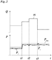
- Fig. 2 is a time diagram illustrating the function of the coolant system.
- a curve 46 in Fig. 2 indicates the time change of the coolant demand Q of the consumers 10 which results from the fact that, at times t1, t2 and t3, there is a switch from one consumer to another or a consumer is switched on or off.
- a thinner continuous line in the lower part Fig. 2 indicates the time dependency of the target pressure P s as determined by the control unit 16. At time t1, the target pressure increases. At the times t2 and t3, the target pressure remains constant although the coolant demand Q changes due to consumers being switched on and off, respectively.
- a curve that has been drawn in dashed lines indicates a corresponding change of the opening pressure P lim .
- the distance between the target pressure P s and the opening pressure P lim is always constant, independent of the absolute height of the target pressure. In a modified embodiment, this distance could also be proportional to the absolute height of the target pressure P s . Optionally, the distance might also be a more complex function of the target pressure.
- a curve drawn in bold lines in Fig. 2 indicates the time dependency of the actual pressure P i . It can be seen, that, due to the control properties of the system, the actual pressure P i always oscillates somewhat about the respective target pressure P s . However, the distance between P lim and P s has been selected such that the opening pressure P lim is not reached during these fluctuations.
- the actual pressure P i increases in accordance with an increase of the target pressure P s .
- there is a temporary drop in the actual pressure because another consumer is switched on. This drop is however counterbalanced immediately by a corresponding increase of the rotary speed of the pump.
- the demand for coolant decreases abruptly, because consumers have been switched off while the target pressure P s remains constant. Because the rotary speed of the motor 18 cannot decrease quickly enough, in this situation, the opening pressure P lim is exceeded for a short time interval, so that the pressure limiting valve 26 opens. In this way, the pressure surge is limited to the opening pressure P lim . While the rotary speed of the pump decreases further, the actual pressure decreases, so that the limiting valve closes again and the pressure settles again so as to oscillate about the target pressure P s .
Landscapes
- Physics & Mathematics (AREA)
- Engineering & Computer Science (AREA)
- Fluid Mechanics (AREA)
- Mechanical Engineering (AREA)
- General Physics & Mathematics (AREA)
- Automation & Control Theory (AREA)
- Thermal Sciences (AREA)
- General Engineering & Computer Science (AREA)
- Control Of Positive-Displacement Pumps (AREA)
- Control Of Fluid Pressure (AREA)
Description
- The invention relates to a coolant system for machine tools, comprising a pump for the coolant, at least one consumer, a pressure sensor for detecting an actual pressure in the coolant system, and a feedback control device acting upon the pump for regulating the pressure in the coolant system to a target pressure.
- A coolant system of this type has been described in
US 2012/015587 A1 . - In machine tools there are typically used a plurality of different tools in one processing cycle. Each tool needs to be cooled by supplying a liquid coolant as long as the tool is in use. Since the demand for coolant is different from tool to tool, manufactures of the tools specify for each tool a specific target pressure which the coolant system must provide.
- In a coolant system of the type that has been described above, the pressure in the system is detected by means of a sensor, and the pump and a pressure valve are regulated so as to maintain the prescribed target pressure.
- Theoretically, a limiting valve could be provided which serves as a safety valve and has a fixed opening pressure which is significantly larger than the highest possible target pressure.
- In the known system, the pump may react upon changes of the demand for pressure only relatively slowly, so that, in specific cases, especially in cases where the demand for coolant decreases abruptly because, e.g., one of the consumers has been switched off, pressure surges may occur that are undesirable although they remain below the opening pressure of the safety valve.
-
DE 10 2010 017 208 A1 describes a coolant system in which a regulating valve controls the coolant pressure in a primary feedback loop and the displacement of the pump is controlled in a secondary feedback loop. - It is an object of the invention to provide a coolant system which has little pumping losses and can nevertheless be quickly adapted to changes in the demand.
- In order to achieve this object, according to the invention, a limiting valve is provided for limiting the pressure of the coolant supplied to the consumer, the limiting valve having a variable opening pressure, and the feedback control device is adapted to adjust the opening pressure in accordance with the target pressure in such a manner that the opening pressure is always a certain amount higher than the target pressure.
- Thus, according to the invention, the limiting valve serves not only as a mere safety valve but has also the function to suppress the undesired pressure surges when the demand for coolant decreases. In that case, it is accepted that, in order to suppress the pressure surges, a certain amount of coolant is drained via the limiting valve, so that the pump losses are slightly increased. Since, however, the phases in which the limiting valve opens are only very short and occur only sporadically, the increase in pumping losses is negligible.
- In order to suppress the pressure surges as far as possible, it would be desirable, that the opening pressure of the limiting valve is only slightly higher than the target pressure. If, however, the pressure difference is too small, it may happen that the limiting valve will open more frequently, just because of the normal control fluctuations of the controller, so that increased pumping losses may occur. For this reason, in practice, the distance between the opening pressure and the target pressure should be adapted to the control fluctuations of the control loop that is formed by the pump, the pressure sensor and the controller.
- Useful optional features of the invention are indicated in the dependent claims.
- In one embodiment, the feedback control device may be configured such that it keeps the distance between the opening pressure and the target pressure constant. In another embodiment, this distance my be varied in proportion to the target pressure.
- An embodiment example will now be described in greater detail in conjunction with the drawings, wherein:
- Fig. 1
- shows a circuit diagram of a coolant system of a machine tool; and
- Fig. 2
- is a time diagram explaining the function of the coolant system.
- The coolant system that has been shown in the drawing comprises three
consumers 10 that are supplied with liquid coolant from apump 12. Adischarge line 14 of thepump 12 branches to the threeconsumers 10 so that they are all supplied with coolant from thesame pump 12. - Each
consumer 10 is formed by a cooling arrangement for a specific tool of the machine tool. The tools differ in their sizes and constructions and consequently also in their demand for coolant. Acontrol unit 16 of the machine tool controls theconsumers 10 such that the cooling arrangement for a given tool is activated (e.g. by opening a valve that has not been shown here) at the very time when this tool is in use. When the machine tool is configured for the simultaneous use of a plurality of tools, a plurality of consumers may be activated simultaneously. - The
pump 12 is driven by amotor 18 the rotary speed of which is controlled by means offrequency converter 20. The frequency of thefrequency converter 20 is determined by afeedback control device 22 that receives a signal indicating the actual pressure Pi in the discharge line from apressure sensor 24 and receives, from thecontrol unit 16, a signal indicating a target pressure Ps that depends upon the current activity of the consumers. - Moreover, the
feedback control device 22 controls apressure limiting valve 26 such that the pressure in thedischarge line 14 is limited to value that depends upon the target pressure. To that end, the limitingvalve 26 receives, from thefeedback control device 22, a signal that indicates the opening pressure Plim of the limiting valve. - The coolant that has been delivered to the tool by an active consumer is collected and, as has been symbolized by a
recirculation line 28 in the drawing, is recirculated to asump 30 from which the coolant may again be sucked-in by thepump 12 via asuction line 32. - A
branch line 34 leads from thedischarge line 14 of the pump to apressure chamber 36 of the limitingvalve 26. Thepressure chamber 36 is delimited by apiston 38 and, consequently, has a variable value. Depending upon the position of thepiston 38, a relief opening 40 of the limitingvalve 26 is kept closed or opened to a smaller or larger extent. Anactuator 42, e.g. a electro-pneumatic actuator, biases thepiston 38 in closing direction (rightwards in the drawing) with a certain closing force that is determined by thefeedback control device 22. When the pressure in thepressure chamber 36 exceeds the opening pressure Plim, the force which the coolant exerts upon thepiston 38 overcomes the closing force of theactuator 42, so that the piston moves leftwards and opens the relief opening 40 and, consequently, a portion of the coolant delivered by thepump 12 is returned to thesump 30 via the relief opening 40 and abypass line 44. In this way, the pressure in thepressure chamber 36 and thedischarge line 14 is limited. - The
feedback control device 22 controls the rotary speed of themotor 18 and hence the displacement of thepump 12 such that the pressure in thedischarge line 14 is kept close to the target pressure Ps which is always a little smaller than the opening pressure Plim of the limiting valve. Then, the displacement of the pump is just sufficient for supplying theconsumer 10 that is currently active with the specified target pressure. - In case of a tool change, the
control unit 16 issues a command to deactivate theconsumer 10 that has heretofore been active and to activate instead the consumer that belongs to the new tool. If necessary, thecontrol device 16 will simultaneously increase or decrease the target pressure Ps. In this case, thefeedback control device 22 commands theactuator 42 to adjust the opening pressure Plim accordingly. - When the new target pressure is smaller than the former target pressure, the
feedback control device 22 causes a decrease of the rotary speed of themotor 18. Since, consequently, the displacement of thepump 12 decreases, the pressure in thepressure chamber 36 is reduced. This does however not cause thepiston 38 to move rightwards, because, simultaneously, the opening pressure and hence the closing force is reduced as well. In this way, the actual pressure will rapidly decrease to the new target pressure. As the case may be, the closing force may even be reduced to such an extent that thepiston 38 moves leftwards and preliminarily opens the relief opening 40 and accelerates the reduction of pressure. - When a tool change implies the use of a tool that requires a higher target pressure, the
feedback control device 22 commands theactuator 42 to increase the opening pressure and the closing force. As a consequence, thepiston 38 is moved rightwards and the volume of thepressure chamber 36 is reduced. In this way, if thepressure chamber 36 has sufficiently large dimension, it can be achieved that theconsumer 10 will be supplied with a sufficient amount of coolant even in a transition phase in which the displacement of the pump has not yet reached the required value. - In a modified embodiment, the
control unit 16 may issue the commands for switching theconsumers 10 and for changing the target pressure with a certain time delay so that, for example, thefeedback control device 22 is caused to "anticipate" a change of the displacement of thepump 12. -
Fig. 2 is a time diagram illustrating the function of the coolant system. - A
curve 46 inFig. 2 indicates the time change of the coolant demand Q of theconsumers 10 which results from the fact that, at times t1, t2 and t3, there is a switch from one consumer to another or a consumer is switched on or off. A thinner continuous line in the lower partFig. 2 indicates the time dependency of the target pressure Ps as determined by thecontrol unit 16. At time t1, the target pressure increases. At the times t2 and t3, the target pressure remains constant although the coolant demand Q changes due to consumers being switched on and off, respectively. A curve that has been drawn in dashed lines indicates a corresponding change of the opening pressure Plim. In the example that has been shown here, the distance between the target pressure Ps and the opening pressure Plim is always constant, independent of the absolute height of the target pressure. In a modified embodiment, this distance could also be proportional to the absolute height of the target pressure Ps. Optionally, the distance might also be a more complex function of the target pressure. - A curve drawn in bold lines in
Fig. 2 indicates the time dependency of the actual pressure Pi. It can be seen, that, due to the control properties of the system, the actual pressure Pi always oscillates somewhat about the respective target pressure Ps. However, the distance between Plim and Ps has been selected such that the opening pressure Plim is not reached during these fluctuations. - At time t1, the actual pressure Pi increases in accordance with an increase of the target pressure Ps. At time t2, there is a temporary drop in the actual pressure because another consumer is switched on. This drop is however counterbalanced immediately by a corresponding increase of the rotary speed of the pump.
- At time t3, the demand for coolant decreases abruptly, because consumers have been switched off while the target pressure Ps remains constant. Because the rotary speed of the
motor 18 cannot decrease quickly enough, in this situation, the opening pressure Plim is exceeded for a short time interval, so that thepressure limiting valve 26 opens. In this way, the pressure surge is limited to the opening pressure Plim. While the rotary speed of the pump decreases further, the actual pressure decreases, so that the limiting valve closes again and the pressure settles again so as to oscillate about the target pressure Ps.
Claims (3)
- A coolant system for machine tools, comprising a pump (12) for the coolant, at least one consumer (10), a pressure sensor (24) for detecting an actual pressure (Pi) in the coolant system, and a feedback control device (22) acting upon the pump (12) for regulating the pressure in the coolant system to a target pressure (Ps), characterized in that a limiting valve (26) is provided for limiting the pressure of the coolant supplied to the consumer, the limiting valve (26) having a variable opening pressure (Plim), and the feedback control device (22) is adapted to adjust the opening pressure (Plim) in accordance with the target pressure (Ps) such that it is always a certain amount larger than the target pressure.
- The coolant system according to claim 1, wherein the feedback control device (22) is adapted to adjust the opening pressure (Plim) to a value that has a constant distance from the target pressure (Ps).
- The coolant system according to claim 1, wherein the feedback control device (26) is adapted to adjust the opening pressure (Plim) to a value that is proportional to the respective target pressure (Ps).
Applications Claiming Priority (2)
| Application Number | Priority Date | Filing Date | Title |
|---|---|---|---|
| DE202011052170U DE202011052170U1 (en) | 2011-12-02 | 2011-12-02 | Coolant system for machine tools |
| PCT/EP2012/066271 WO2013079229A1 (en) | 2011-12-02 | 2012-08-21 | Coolant system for machine tools |
Publications (2)
| Publication Number | Publication Date |
|---|---|
| EP2786217A1 EP2786217A1 (en) | 2014-10-08 |
| EP2786217B1 true EP2786217B1 (en) | 2018-08-01 |
Family
ID=46682850
Family Applications (1)
| Application Number | Title | Priority Date | Filing Date |
|---|---|---|---|
| EP12748040.8A Active EP2786217B1 (en) | 2011-12-02 | 2012-08-21 | Coolant system for machine tools |
Country Status (7)
| Country | Link |
|---|---|
| US (1) | US9488421B2 (en) |
| EP (1) | EP2786217B1 (en) |
| JP (1) | JP2015501733A (en) |
| CN (1) | CN103946759B (en) |
| DE (1) | DE202011052170U1 (en) |
| TW (1) | TWI477345B (en) |
| WO (1) | WO2013079229A1 (en) |
Families Citing this family (7)
| Publication number | Priority date | Publication date | Assignee | Title |
|---|---|---|---|---|
| EP2756920B1 (en) * | 2011-09-16 | 2019-03-27 | Makino Milling Machine Co. Ltd. | Coolant supply device |
| US20180104750A1 (en) * | 2016-10-18 | 2018-04-19 | United Technologies Corporation | Feedback-controlled system for cyrogenically cooling machining tools |
| DE102017209822B4 (en) * | 2017-06-09 | 2020-04-16 | Mag Ias Gmbh | Method for operating a machine tool and machine tool |
| DE102017129840B4 (en) * | 2017-12-13 | 2020-07-09 | Fritz Studer Ag | Nozzle arrangement and machine tool with a nozzle arrangement |
| CN108202271B (en) * | 2018-03-14 | 2024-04-19 | 广东技术师范大学 | Low-temperature micro-lubrication device based on supercritical carbon dioxide |
| CN111055162A (en) * | 2019-12-31 | 2020-04-24 | 成都理工大学 | An automatic control-based minimal quantity lubrication device |
| DE102022116629A1 (en) * | 2022-07-04 | 2024-01-04 | Jungheinrich Aktiengesellschaft | Method for operating an industrial truck with a mast lift and a hydraulic unit |
Family Cites Families (25)
| Publication number | Priority date | Publication date | Assignee | Title |
|---|---|---|---|---|
| US4791958A (en) * | 1983-12-21 | 1988-12-20 | Brundage Robert W | Solenoid controlled fluid valve |
| DD252144A1 (en) * | 1986-09-01 | 1987-12-09 | Werkzeugmasch Forschzent | DEVICE FOR APPLYING LUBRICANTS TO WORKSPIECES OR TOOLS |
| DE9112716U1 (en) * | 1991-07-09 | 1992-02-13 | Allweiler Ag, 7760 Radolfzell | Device for pumping liquids with a pump |
| US5297657A (en) * | 1991-07-25 | 1994-03-29 | Brittani-7, Inc. | High pressure coolant system for machine tools |
| WO1994027041A1 (en) * | 1993-05-06 | 1994-11-24 | Cummins Engine Company, Inc. | Compact high performance fuel system with accumulator |
| US5522707A (en) * | 1994-11-16 | 1996-06-04 | Metropolitan Industries, Inc. | Variable frequency drive system for fluid delivery system |
| DE19725345C2 (en) * | 1997-06-16 | 2002-11-07 | Bielomatik Leuze & Co | lubricator |
| US5951216A (en) * | 1997-09-19 | 1999-09-14 | Antoun; Gregory S. | Programmable, variable volume and pressure, coolant system |
| US6241432B1 (en) * | 1998-10-23 | 2001-06-05 | Brookdale Associates | Machine tool accessory high pressure fluid distribution system |
| US6874977B2 (en) * | 2002-02-04 | 2005-04-05 | Morrell Incorporated | High pressure coolant system |
| JP2004074331A (en) * | 2002-08-13 | 2004-03-11 | Shin Caterpillar Mitsubishi Ltd | Operating fluid feed control system for breaker, and feed control method |
| JP4250999B2 (en) * | 2003-04-10 | 2009-04-08 | ダイキン工業株式会社 | Coolant pump device and drill device |
| DE102004061559A1 (en) * | 2004-12-21 | 2006-06-29 | Brueninghaus Hydromatik Gmbh | Hydraulic drive |
| DE102006052602B4 (en) * | 2006-10-06 | 2010-05-12 | Walter Mauch | Method and device for supplying coolant to cutting tools |
| CN201288657Y (en) * | 2008-09-28 | 2009-08-12 | 海特克液压有限公司 | Electro-hydraulic integration dual chamber power variant control apparatus |
| US20100206882A1 (en) * | 2009-02-13 | 2010-08-19 | Wessels Timothy J | Multi chamber coolant tank |
| JP2010223371A (en) * | 2009-03-24 | 2010-10-07 | Komatsu Ltd | Hydraulic drive |
| DE102010032599A1 (en) * | 2009-08-05 | 2011-02-10 | Robert Bosch Gmbh | Device for cooling lubricant supply for tool, comprises quantity-controlled variable pump, where constant volumetric flow of cooling lubricant is dispersed over tool |
| US8359941B2 (en) * | 2009-09-29 | 2013-01-29 | GM Global Technology Operations LLC | Hydraulic control systems for dual clutch transmissions |
| CN101695765A (en) * | 2009-10-15 | 2010-04-21 | 浙江大学 | Hydraulic power chuck controlled by electro-hydraulic proportional pressure valve |
| DE102010017208B4 (en) * | 2010-06-02 | 2014-05-15 | Brinkmann Pumpen K.H. Brinkmann Gmbh & Co. Kg | Coolant system for machine tools |
| US8568198B2 (en) * | 2010-07-16 | 2013-10-29 | Pratt & Whitney Canada Corp. | Active coolant flow control for machining processes |
| FR2972952B1 (en) * | 2011-03-23 | 2013-05-10 | Messier Bugatti | METHOD FOR CONTROLLING A WATERING DEVICE FOR MACHINING MACHINE |
| CN202021343U (en) * | 2011-03-30 | 2011-11-02 | 成都四星液压制造有限公司 | Hydraulic system variable control device for automatic wet press for magnetic materials |
| EP2756920B1 (en) * | 2011-09-16 | 2019-03-27 | Makino Milling Machine Co. Ltd. | Coolant supply device |
-
2011
- 2011-12-02 DE DE202011052170U patent/DE202011052170U1/en not_active Expired - Lifetime
-
2012
- 2012-08-21 CN CN201280057480.4A patent/CN103946759B/en not_active Expired - Fee Related
- 2012-08-21 JP JP2014543810A patent/JP2015501733A/en active Pending
- 2012-08-21 WO PCT/EP2012/066271 patent/WO2013079229A1/en not_active Ceased
- 2012-08-21 US US14/358,522 patent/US9488421B2/en not_active Expired - Fee Related
- 2012-08-21 EP EP12748040.8A patent/EP2786217B1/en active Active
- 2012-10-17 TW TW101138239A patent/TWI477345B/en not_active IP Right Cessation
Also Published As
| Publication number | Publication date |
|---|---|
| US9488421B2 (en) | 2016-11-08 |
| TW201323141A (en) | 2013-06-16 |
| EP2786217A1 (en) | 2014-10-08 |
| CN103946759B (en) | 2016-06-29 |
| WO2013079229A1 (en) | 2013-06-06 |
| DE202011052170U1 (en) | 2013-03-04 |
| TWI477345B (en) | 2015-03-21 |
| JP2015501733A (en) | 2015-01-19 |
| US20140262197A1 (en) | 2014-09-18 |
| CN103946759A (en) | 2014-07-23 |
Similar Documents
| Publication | Publication Date | Title |
|---|---|---|
| US9488421B2 (en) | Coolant system for machine tools | |
| EP1813362B1 (en) | Die cushion device of pressing machine | |
| JP5651196B2 (en) | Positive displacement pump operation control device, pump system, and operating method thereof | |
| KR20040049277A (en) | Method and device for attenuating the motion of hydraulic cylinders of mobile work machinery | |
| KR101045721B1 (en) | Pump Torque Control Device Of Hydraulic Work Machine | |
| JP4629168B2 (en) | Positive flow control device | |
| EP3099861A1 (en) | Engine and pump control device and working machine | |
| US10221870B2 (en) | Felling saw recovery control | |
| KR101582689B1 (en) | Swing control apparatus and swing control method for construction machinery | |
| KR101143022B1 (en) | Confluent control system | |
| EP3670763B1 (en) | Hydraulic system | |
| EP2801724B1 (en) | Pressure overshooting prevention system for electronic hydraulic pump in hydraulic system | |
| JP2011021694A (en) | Revolution hydraulic control device for working machine | |
| US20170037600A1 (en) | Drive control device for construction equipment and control method therefor | |
| KR101740925B1 (en) | Hydraulic assembly comprising a variable displacement pump and a relief valve | |
| KR101164669B1 (en) | Method of and apparatus for controlling swing operation of an excavator | |
| JP2003120605A (en) | Hydraulic driving device for hydraulic machine | |
| CN114787520A (en) | Hydraulic pump system and control device | |
| EP4435272A1 (en) | Open centre hydraulic distributor and power transmission system for transmitting to users of an operating machine | |
| JP6750366B2 (en) | Merge control system |
Legal Events
| Date | Code | Title | Description |
|---|---|---|---|
| PUAI | Public reference made under article 153(3) epc to a published international application that has entered the european phase |
Free format text: ORIGINAL CODE: 0009012 |
|
| 17P | Request for examination filed |
Effective date: 20140430 |
|
| AK | Designated contracting states |
Kind code of ref document: A1 Designated state(s): AL AT BE BG CH CY CZ DE DK EE ES FI FR GB GR HR HU IE IS IT LI LT LU LV MC MK MT NL NO PL PT RO RS SE SI SK SM TR |
|
| DAX | Request for extension of the european patent (deleted) | ||
| REG | Reference to a national code |
Ref country code: DE Ref legal event code: R079 Ref document number: 602012049145 Country of ref document: DE Free format text: PREVIOUS MAIN CLASS: G05D0016200000 Ipc: F28F0027000000 |
|
| RIC1 | Information provided on ipc code assigned before grant |
Ipc: F28F 27/00 20060101AFI20171220BHEP |
|
| GRAP | Despatch of communication of intention to grant a patent |
Free format text: ORIGINAL CODE: EPIDOSNIGR1 |
|
| INTG | Intention to grant announced |
Effective date: 20180221 |
|
| GRAS | Grant fee paid |
Free format text: ORIGINAL CODE: EPIDOSNIGR3 |
|
| GRAA | (expected) grant |
Free format text: ORIGINAL CODE: 0009210 |
|
| AK | Designated contracting states |
Kind code of ref document: B1 Designated state(s): AL AT BE BG CH CY CZ DE DK EE ES FI FR GB GR HR HU IE IS IT LI LT LU LV MC MK MT NL NO PL PT RO RS SE SI SK SM TR |
|
| REG | Reference to a national code |
Ref country code: GB Ref legal event code: FG4D |
|
| REG | Reference to a national code |
Ref country code: CH Ref legal event code: EP Ref country code: AT Ref legal event code: REF Ref document number: 1024806 Country of ref document: AT Kind code of ref document: T Effective date: 20180815 |
|
| REG | Reference to a national code |
Ref country code: IE Ref legal event code: FG4D |
|
| REG | Reference to a national code |
Ref country code: DE Ref legal event code: R096 Ref document number: 602012049145 Country of ref document: DE |
|
| REG | Reference to a national code |
Ref country code: NL Ref legal event code: MP Effective date: 20180801 |
|
| REG | Reference to a national code |
Ref country code: LT Ref legal event code: MG4D |
|
| REG | Reference to a national code |
Ref country code: AT Ref legal event code: MK05 Ref document number: 1024806 Country of ref document: AT Kind code of ref document: T Effective date: 20180801 |
|
| PG25 | Lapsed in a contracting state [announced via postgrant information from national office to epo] |
Ref country code: BG Free format text: LAPSE BECAUSE OF FAILURE TO SUBMIT A TRANSLATION OF THE DESCRIPTION OR TO PAY THE FEE WITHIN THE PRESCRIBED TIME-LIMIT Effective date: 20181101 Ref country code: NO Free format text: LAPSE BECAUSE OF FAILURE TO SUBMIT A TRANSLATION OF THE DESCRIPTION OR TO PAY THE FEE WITHIN THE PRESCRIBED TIME-LIMIT Effective date: 20181101 Ref country code: SE Free format text: LAPSE BECAUSE OF FAILURE TO SUBMIT A TRANSLATION OF THE DESCRIPTION OR TO PAY THE FEE WITHIN THE PRESCRIBED TIME-LIMIT Effective date: 20180801 Ref country code: GR Free format text: LAPSE BECAUSE OF FAILURE TO SUBMIT A TRANSLATION OF THE DESCRIPTION OR TO PAY THE FEE WITHIN THE PRESCRIBED TIME-LIMIT Effective date: 20181102 Ref country code: IS Free format text: LAPSE BECAUSE OF FAILURE TO SUBMIT A TRANSLATION OF THE DESCRIPTION OR TO PAY THE FEE WITHIN THE PRESCRIBED TIME-LIMIT Effective date: 20181201 Ref country code: AT Free format text: LAPSE BECAUSE OF FAILURE TO SUBMIT A TRANSLATION OF THE DESCRIPTION OR TO PAY THE FEE WITHIN THE PRESCRIBED TIME-LIMIT Effective date: 20180801 Ref country code: RS Free format text: LAPSE BECAUSE OF FAILURE TO SUBMIT A TRANSLATION OF THE DESCRIPTION OR TO PAY THE FEE WITHIN THE PRESCRIBED TIME-LIMIT Effective date: 20180801 Ref country code: FI Free format text: LAPSE BECAUSE OF FAILURE TO SUBMIT A TRANSLATION OF THE DESCRIPTION OR TO PAY THE FEE WITHIN THE PRESCRIBED TIME-LIMIT Effective date: 20180801 Ref country code: LT Free format text: LAPSE BECAUSE OF FAILURE TO SUBMIT A TRANSLATION OF THE DESCRIPTION OR TO PAY THE FEE WITHIN THE PRESCRIBED TIME-LIMIT Effective date: 20180801 Ref country code: PL Free format text: LAPSE BECAUSE OF FAILURE TO SUBMIT A TRANSLATION OF THE DESCRIPTION OR TO PAY THE FEE WITHIN THE PRESCRIBED TIME-LIMIT Effective date: 20180801 Ref country code: NL Free format text: LAPSE BECAUSE OF FAILURE TO SUBMIT A TRANSLATION OF THE DESCRIPTION OR TO PAY THE FEE WITHIN THE PRESCRIBED TIME-LIMIT Effective date: 20180801 |
|
| PG25 | Lapsed in a contracting state [announced via postgrant information from national office to epo] |
Ref country code: HR Free format text: LAPSE BECAUSE OF FAILURE TO SUBMIT A TRANSLATION OF THE DESCRIPTION OR TO PAY THE FEE WITHIN THE PRESCRIBED TIME-LIMIT Effective date: 20180801 Ref country code: AL Free format text: LAPSE BECAUSE OF FAILURE TO SUBMIT A TRANSLATION OF THE DESCRIPTION OR TO PAY THE FEE WITHIN THE PRESCRIBED TIME-LIMIT Effective date: 20180801 Ref country code: LV Free format text: LAPSE BECAUSE OF FAILURE TO SUBMIT A TRANSLATION OF THE DESCRIPTION OR TO PAY THE FEE WITHIN THE PRESCRIBED TIME-LIMIT Effective date: 20180801 |
|
| PG25 | Lapsed in a contracting state [announced via postgrant information from national office to epo] |
Ref country code: EE Free format text: LAPSE BECAUSE OF FAILURE TO SUBMIT A TRANSLATION OF THE DESCRIPTION OR TO PAY THE FEE WITHIN THE PRESCRIBED TIME-LIMIT Effective date: 20180801 Ref country code: CZ Free format text: LAPSE BECAUSE OF FAILURE TO SUBMIT A TRANSLATION OF THE DESCRIPTION OR TO PAY THE FEE WITHIN THE PRESCRIBED TIME-LIMIT Effective date: 20180801 Ref country code: RO Free format text: LAPSE BECAUSE OF FAILURE TO SUBMIT A TRANSLATION OF THE DESCRIPTION OR TO PAY THE FEE WITHIN THE PRESCRIBED TIME-LIMIT Effective date: 20180801 Ref country code: ES Free format text: LAPSE BECAUSE OF FAILURE TO SUBMIT A TRANSLATION OF THE DESCRIPTION OR TO PAY THE FEE WITHIN THE PRESCRIBED TIME-LIMIT Effective date: 20180801 Ref country code: MC Free format text: LAPSE BECAUSE OF FAILURE TO SUBMIT A TRANSLATION OF THE DESCRIPTION OR TO PAY THE FEE WITHIN THE PRESCRIBED TIME-LIMIT Effective date: 20180801 Ref country code: LU Free format text: LAPSE BECAUSE OF NON-PAYMENT OF DUE FEES Effective date: 20180821 |
|
| REG | Reference to a national code |
Ref country code: DE Ref legal event code: R097 Ref document number: 602012049145 Country of ref document: DE |
|
| REG | Reference to a national code |
Ref country code: BE Ref legal event code: MM Effective date: 20180831 |
|
| PG25 | Lapsed in a contracting state [announced via postgrant information from national office to epo] |
Ref country code: SK Free format text: LAPSE BECAUSE OF FAILURE TO SUBMIT A TRANSLATION OF THE DESCRIPTION OR TO PAY THE FEE WITHIN THE PRESCRIBED TIME-LIMIT Effective date: 20180801 Ref country code: DK Free format text: LAPSE BECAUSE OF FAILURE TO SUBMIT A TRANSLATION OF THE DESCRIPTION OR TO PAY THE FEE WITHIN THE PRESCRIBED TIME-LIMIT Effective date: 20180801 Ref country code: SM Free format text: LAPSE BECAUSE OF FAILURE TO SUBMIT A TRANSLATION OF THE DESCRIPTION OR TO PAY THE FEE WITHIN THE PRESCRIBED TIME-LIMIT Effective date: 20180801 |
|
| PLBE | No opposition filed within time limit |
Free format text: ORIGINAL CODE: 0009261 |
|
| STAA | Information on the status of an ep patent application or granted ep patent |
Free format text: STATUS: NO OPPOSITION FILED WITHIN TIME LIMIT |
|
| 26N | No opposition filed |
Effective date: 20190503 |
|
| GBPC | Gb: european patent ceased through non-payment of renewal fee |
Effective date: 20181101 |
|
| PG25 | Lapsed in a contracting state [announced via postgrant information from national office to epo] |
Ref country code: SI Free format text: LAPSE BECAUSE OF FAILURE TO SUBMIT A TRANSLATION OF THE DESCRIPTION OR TO PAY THE FEE WITHIN THE PRESCRIBED TIME-LIMIT Effective date: 20180801 Ref country code: FR Free format text: LAPSE BECAUSE OF NON-PAYMENT OF DUE FEES Effective date: 20181001 Ref country code: BE Free format text: LAPSE BECAUSE OF NON-PAYMENT OF DUE FEES Effective date: 20180831 |
|
| PG25 | Lapsed in a contracting state [announced via postgrant information from national office to epo] |
Ref country code: GB Free format text: LAPSE BECAUSE OF NON-PAYMENT OF DUE FEES Effective date: 20181101 |
|
| PG25 | Lapsed in a contracting state [announced via postgrant information from national office to epo] |
Ref country code: MT Free format text: LAPSE BECAUSE OF NON-PAYMENT OF DUE FEES Effective date: 20180821 |
|
| PG25 | Lapsed in a contracting state [announced via postgrant information from national office to epo] |
Ref country code: TR Free format text: LAPSE BECAUSE OF FAILURE TO SUBMIT A TRANSLATION OF THE DESCRIPTION OR TO PAY THE FEE WITHIN THE PRESCRIBED TIME-LIMIT Effective date: 20180801 |
|
| PG25 | Lapsed in a contracting state [announced via postgrant information from national office to epo] |
Ref country code: HU Free format text: LAPSE BECAUSE OF FAILURE TO SUBMIT A TRANSLATION OF THE DESCRIPTION OR TO PAY THE FEE WITHIN THE PRESCRIBED TIME-LIMIT; INVALID AB INITIO Effective date: 20120821 Ref country code: PT Free format text: LAPSE BECAUSE OF FAILURE TO SUBMIT A TRANSLATION OF THE DESCRIPTION OR TO PAY THE FEE WITHIN THE PRESCRIBED TIME-LIMIT Effective date: 20180801 |
|
| PG25 | Lapsed in a contracting state [announced via postgrant information from national office to epo] |
Ref country code: CY Free format text: LAPSE BECAUSE OF FAILURE TO SUBMIT A TRANSLATION OF THE DESCRIPTION OR TO PAY THE FEE WITHIN THE PRESCRIBED TIME-LIMIT Effective date: 20180801 Ref country code: IE Free format text: LAPSE BECAUSE OF NON-PAYMENT OF DUE FEES Effective date: 20180821 Ref country code: MK Free format text: LAPSE BECAUSE OF NON-PAYMENT OF DUE FEES Effective date: 20180801 |
|
| PGFP | Annual fee paid to national office [announced via postgrant information from national office to epo] |
Ref country code: DE Payment date: 20250827 Year of fee payment: 14 |
|
| PGFP | Annual fee paid to national office [announced via postgrant information from national office to epo] |
Ref country code: IT Payment date: 20250829 Year of fee payment: 14 |
|
| PGFP | Annual fee paid to national office [announced via postgrant information from national office to epo] |
Ref country code: CH Payment date: 20250901 Year of fee payment: 14 |