EP2786087B1 - Silencer for a firearm - Google Patents
Silencer for a firearm Download PDFInfo
- Publication number
- EP2786087B1 EP2786087B1 EP12809133.7A EP12809133A EP2786087B1 EP 2786087 B1 EP2786087 B1 EP 2786087B1 EP 12809133 A EP12809133 A EP 12809133A EP 2786087 B1 EP2786087 B1 EP 2786087B1
- Authority
- EP
- European Patent Office
- Prior art keywords
- silencer
- cut
- attachment part
- attachment
- circumference
- Prior art date
- Legal status (The legal status is an assumption and is not a legal conclusion. Google has not performed a legal analysis and makes no representation as to the accuracy of the status listed.)
- Active
Links
Images



Classifications
-
- F—MECHANICAL ENGINEERING; LIGHTING; HEATING; WEAPONS; BLASTING
- F41—WEAPONS
- F41A—FUNCTIONAL FEATURES OR DETAILS COMMON TO BOTH SMALLARMS AND ORDNANCE, e.g. CANNONS; MOUNTINGS FOR SMALLARMS OR ORDNANCE
- F41A21/00—Barrels; Gun tubes; Muzzle attachments; Barrel mounting means
- F41A21/30—Silencers
-
- F—MECHANICAL ENGINEERING; LIGHTING; HEATING; WEAPONS; BLASTING
- F41—WEAPONS
- F41A—FUNCTIONAL FEATURES OR DETAILS COMMON TO BOTH SMALLARMS AND ORDNANCE, e.g. CANNONS; MOUNTINGS FOR SMALLARMS OR ORDNANCE
- F41A21/00—Barrels; Gun tubes; Muzzle attachments; Barrel mounting means
- F41A21/32—Muzzle attachments or glands
- F41A21/325—Mountings for muzzle attachments
Definitions
- the present invention relates to a silencer for a firearm, such as a rifle or a pistol, where the silencer comprises a substantially cylindrical casing and where the silencer is intended to be releasably connected to an attachment element which is mounted on the barrel of the firearm.
- the present invention also relates to an attachment element which is intended to be releasably connected to a silencer according to the present invention.
- Silencers are used with high-pressure firearms in particular, since in many situations the report when the weapon is fired will be too loud. By means of its construction the silencer will be able to reduce the report and the recoil when shots are fired, thereby avoiding damage to hearing as well as making the marksman feel safer when firing a shot as the recoil is reduced.
- the above silencers are designed to be able to be releasably connected to the barrel of the firearm.
- the silencer will then be provided with an internally threaded portion, where this threaded portion may either be arranged in the cylindrical casing or also arranged at an end of the silencer, which end will therefore form the silencer's attachment part.
- the firearm's barrel will then be provided with a corresponding and externally threaded portion over a part of its length, where this threaded portion may be provided at the end of the barrel or a distance into the barrel.
- the silencer will then be able to be screwed off and on to the firearm's barrel as required.
- GB 24.766 relates to a device for lessening the report of a firearm, in which the energy with which the gases of combustion travel is destroyed by guiding said gases through a certain number of chambers so that the gases are deviated from the trajectory and made to expand in said chambers.
- the device has a sleeve which fits on to the barrel of the firearm.
- An angular slot at the free end of the sleeve serves to fix the device to the barrel, said slot being pushed over the sight.
- US 5.559.302 A relates to a bayonet coupling for removably mounting accessories on an end of a gun barrel, wherein the gun barrel includes at least one lug spaced from the barrel end.
- a coupling adapter receives the gun barrel end and lugs and includes lug retaining recesses which receive the lugs upon relative rotation between the gun barrel and adapter occurring.
- a compressible spring located within the adapter biases an annular lug engaging sleeve wherein lug retention within the adapter recesses is maintained by the spring and only an axial movement of the adapter on the gun barrel is required to disengage the lug and its retaining recess to permit rotation of the adapter for quick adapter mounting and removal.
- the object of the present invention is to provide a silencer which can be connected to and removed from a firearm's barrel in a simple and safe manner, and which consists of a small number of parts.
- the present invention relates to a silencer for a firearm and an associated attachment element, where the silencer is designed to be able to be releasably connected to the attachment element which is mounted on the barrel of the firearm.
- a first embodiment of the silencer according to the present invention comprises a substantially cylindrical housing which is provided with an attachment part, an intermediate part and an outer muzzle part, where in the intermediate part a number of elements are arranged which will be capable of suppressing the sound of a report resulting from the firing of the weapon.
- the silencer is further designed to be releasably connected with an attachment element mounted on the barrel of a firearm, in which case the silencer's attachment part, i.e.
- the part of the silencer which has to be connected to the attachment element is provided with a number of cut-outs round its circumference, where each cut-out is composed of a portion extending a distance in the silencer's longitudinal direction and a portion extending a distance over the circumference of the attachment part, which two portions are connected with an intermediate portion.
- at least one of the cut-outs is provided with at least one bead, in order thereby to create a narrowing of the portion of the cut-out extending a distance over the circumference of the attachment part, where adjacent to this portion at least one additional slot is provided extending over the circumference of the attachment part.
- the cut-outs will be provided passing through the material of the attachment part.
- the at least one slot which is arranged adjacent to the portion of the cut-out provided with at least one bead will be designed to have the same length as the adjacent portion, in which case the slot will have a width or height which is less than the width of the adjacent portion with the bead. It should be understood, however, that the slot may be designed to have other lengths and/or widths.
- the slot moreover, is preferably arranged between the silencer's intermediate part and the portion with the bead, but may also be arranged on an opposite side of the portion with the bead, or on both sides of the portion with the bead.
- the slot may furthermore extend parallel to the portion with the bead, and the slot may also be composed of several smaller holes, partial slots etc. arranged one behind the other, where these will have the same function as the slot.
- the slot will act as a spring element, as the slot and the portion with the bead will be separated by a distance element with relatively little width or height in accordance with the design of the cut-out and the slot, where this distance element will then be permitted to be moved in the silencer's longitudinal direction when by means of the attachment part the silencer has to be connected to an attachment element which is mounted on the firearm's barrel, since the attachment element is provided with a number of locking pins corresponding to the cut-outs with which the silencer's attachment part is provided.
- the intermediate portion connecting the portion of the cut-out which extends a distance in the silencer's longitudinal direction and the portion of the cut-out which extends a distance over the circumference of the attachment part, in order thereby to form the cut-out may be provided at least over a part of its length with a straight piece, where this straight piece is arranged so as to form an angle with both the portion of the cut-out which extends a distance in the silencer's longitudinal direction and the portion of the cut-out which extends a distance over the circumference of the attachment part.
- This design of the cut-out will provide a force which will help to separate the silencer and the attachment element when the silencer has to be released from the attachment element, since on account of the design of the intermediate portion, the locking pins in the attachment element will be forced out of engagement with the portion of the cut-out which extends a distance over the circumference of the attachment part when the silencer is screwed about its longitudinal direction, with the result that the locking pins are inserted in the portion which extends a distance in the silencer's longitudinal direction.
- the intermediate portion's design will force the locking pins into engagement with the portion of the cut-out which extends a distance over the circumference of the attachment part when the silencer has to be connected to the attachment element which is mounted on the barrel of the firearm.
- the silencer's attachment part is provided with four cut-outs which are arranged at an equal distance apart, for example located at 90 degrees apart from one another, and where two of these cut-outs are provided with a bead. Adjacent to each of these cut-outs with bead there is also provided a slot extending over the circumference of the attachment part.
- the attachment part may also be provided with a greater or smaller number of cut-outs, for example three, where the cut-outs may be arranged at an equal or unequal distance relative to one another, and where fewer or all the cut-outs may be provided with a bead.
- several beads may also be provided in this portion.
- the two other cut-outs will then be provided with an intermediate portion which is provided over at least a part of its length with a straight piece, with the result that these two cut-outs will produce a force which will provide help when silencer and attachment element have to be connected or released.
- the silencer's attachment part is provided with three cut-outs which are arranged at 120 degrees relative to one another.
- a cut-out may, for example, be provided with at least one bead, and where adjacent to this cut-out a slot is provided extending over the circumference of the attachment part, while two cut-outs will then be provided with an intermediate portion which is provided over at least a part of its length with a straight piece, with the result that these two cut-outs will produce a force which will provide help when silencer and attachment element have to be connected or released.
- the cut-outs have a J or L-shape, but may also have other geometrical shapes which will enable a releasable locking to be achieved between the silencer and the attachment element.
- the at least one bead which is provided in the portion of the cut-out extending a distance over the circumference of the attachment part is arranged located outside the portion extending a distance in the silencer's longitudinal direction.
- the at least one bead will furthermore extend into the portion of the cut-out which extends a distance over the circumference of the attachment part, with the result that the at least one bead will create a narrowing of this portion.
- portion of the cut-out which extends a distance over the circumference of the attachment part may be provided with several beads arranged behind one another, where the bead or beads may have a geometry which results in the need to apply an extra force in order to move the attachment element's locking pins past the bead or beads.
- the beads may have the same or different geometry and/or dimensions.
- the silencer When the silencer according to the present invention has to be connected to the attachment element mounted on the firearm's barrel, the silencer will be inserted towards the attachment element's locking pins, so that the locking pins are inserted into the portions of the cut-outs which extend a distance in the silencer's longitudinal direction.
- the silencer When the locking pins have come into contact with the intermediate portion of the cut-out, the silencer will begin to be rotated about its longitudinal axis, whereby this rotation will cause the straight piece in the intermediate portion of the cut-out to force the locking pins into engagement with the portion of the cut-out extending a distance over the circumference of the attachment part.
- the locking pins After the locking pins have been inserted a distance into the portion of the cut-out extending a distance in the circumference of the attachment part, at least one of the locking pins will be brought into contact with the at least one bead.
- the locking pin By means of a further rotation of the silencer, the locking pin will be brought past the bead, since by means of this rotation the distance element will be deflected in towards the adjacent slot, thereby enabling the locking pin to be moved past the bead.
- the distance element When the locking pin has been moved past the bead, the distance element will assume its original position again, thereby locking the locking pin in the cut-out.
- the distance element will be able to flex in the silencer's longitudinal direction when a locking pin is moved past the bead(s), whereupon the distance element will assume its original position when the locking pin has been moved past the bead(s).
- the distance element is designed to be able to flex in the silencer's radial direction.
- the silencer's attachment part will then be provided in a similar manner to that indicated above with a number of cut-outs, slots, etc., but in this case the cut-outs will not be designed to pass through the material of the attachment part.
- At least two slots will be provided adjacent to the portion of the non-through-going cut-out which extends a distance over the circumference of the attachment part, where one of the slots is arranged between the silencer's intermediate part and the portion extending a distance over the circumference of the attachment part, and where the second slot is arranged between the portion extending a distance over the circumference of the attachment part and the attachment part's end termination, with the result that the slots are arranged on each side of the portion extending a distance over the circumference of the attachment part. Near one of the ends of the slots an additional slot is further provided, where this slot will extend over both the slots.
- the three slots will therefore form a distance element, which distance element will be flexible in the silencer's radial direction.
- This distance element will then be provided with at least one bead, where this bead is arranged on the inside of the distance element, extending radially into the silencer, in order thereby to create a radial narrowing of the portion of the cut-out which extends a distance over the circumference of the attachment part.
- this embodiment of the silencer could otherwise be designed in a similar manner to that indicated with regard to the first embodiment of the silencer.
- the assembly of the silencer and the attachment element will also be accomplished as explained above with regard to the first embodiment of the silencer, except for the fact that the distance element will now be radially flexible.
- the present invention also relates to an attachment element for a silencer, where the attachment element is designed to be able to be mounted on the barrel of a firearm.
- the attachment element comprises a casing element with a flange part which is provided with an outer and inner flange, where the outer flange is arranged to interact with an abutment shoulder in a silencer's attachment part, while the inner flange is arranged to interact with an outer abutment surface in the barrel of a firearm.
- the outer flange will then be provided with a diameter which is approximately equal to the attachment part's internal diameter, while the inner flange has a diameter which at least is approximately equal to a diameter of the barrel of the firearm, at least over a part of the barrel's length.
- the attachment element is further provided with a number of locking pins over its circumference, which locking pins are designed to interact with a corresponding number of cut-outs in the silencer's attachment part.
- the locking pins are designed to have a length which will be flush with an outer diameter of the silencer's attachment part when the silencer is connected with the attachment element. It should be understood, however, that the locking pins may be designed to have other lengths, where the locking pins furthermore may have the same or different length, thickness etc.
- the attachment element according to the present invention could be an independent element which is designed to be mounted in a suitable manner on a firearm's barrel, for example by being provided with threads, thereby enabling the attachment element to be screwed on to the firearm's barrel, or the attachment element may be designed to be able to be mounted between the firearm's barrel and a flash eliminator, muzzle brake or the like.
- the attachment element may also be integrated in the firearm's barrel, flash eliminator, muzzle brake or the like.
- FIG 1 a first embodiment is illustrated of a silencer 1 and an attachment element 2 according to the present invention depicted connected to each other, where the silencer 1 comprises an attachment part 3, an intermediate part 4 and an outer muzzle part 5.
- a number of elements E are mounted which will be capable of suppressing the sound of a report produced during firing of a weapon (not shown).
- a person skilled in the art will know what constitutes the elements E and how they should be constructed, and therefore this will not be discussed further here.
- the silencer's (1) attachment part 3 is provided with four cut-outs 6, the cut-outs 6 being arranged in twos diametrically above one another.
- the cut-outs 6 are composed of a portion 6A which extends a distance in the silencer's 1 longitudinal direction and a portion 6B which extends a distance over the circumference of the attachment part 3.
- the portions 6A, 6B are further connected by an intermediate portion 6C, in order thereby to provide a J-shaped cut-out.
- At least one cut-out 6 in the attachment part 3, see the lower part of figure 1 will be designed to achieve a releasable locking with a locking pin 7 in the attachment element 2.
- This cut-out 6 will then be provided with a portion 6B which extends a longer distance over the circumference of the attachment part 3 than the other cut-outs 6, see also figure 3 .
- a bead 8 is provided, where this bead 8 is arranged in an area of the portion 6B located outside the intermediate portion 6C and the portion 6A of the cut-out 6.
- the bead 8 will furthermore extend into the portion 6B, so that the bead 8 creates a narrowing of the portion 6B.
- a slot 9 is provided, where the slot 9 extends parallel to the intermediate portion 6C and the portion 6B of the cut-out 6.
- the slot 9 and the portions 6B, 6C will then be separated by a distance element 10, which is provided with the bead 8, where the portion 6B, the distance element 10 and the slot 9 will interact in order to achieve a releasable connection between the silencer 1 and the attachment element 2. This will be explained in more detail below.
- the other cut-outs 6 in the silencer's 1 attachment part 3 will then be designed like the cut-out 6 as illustrated in the upper part of figure 1 ; in a similar manner, the cut-out 6 shown here will comprise a portion 6A extending a distance in the silencer's 1 longitudinal direction and a portion 6B extending a distance over the circumference of the attachment part 3, where the portions 6A, 6B are connected by an intermediate portion 6C, in order thereby to form a J-shaped cut-out. Over a part of its length the intermediate portion 6C is provided with a straight piece 6C 1 , where this straight piece 6C 1 then forms an angle with both the portions 6A, 6B.
- This design of the portion 6C 1 will provide a force which will help to separate silencer 1 and attachment element 2 when the silencer 1 has to be separated from the attachment element 2, since, on account of the straight piece 6C 1 , the locking pins 7 in the attachment element 2 will be forced out of engagement with the portion 6B when the silencer 1 is rotated about its longitudinal direction, with the result that the locking pins 7 are guided into the portion 6A in the cut-out 6.
- the straight portion 6C 1 will force the locking pins 7 into engagement with the portion 6B when the silencer 1 has to be connected to the attachment element 2 mounted on the barrel L of a firearm.
- the silencer 1 illustrated in figure 1 is provided with four cut-outs 6, where two of the cut-outs 6 are provided with a bead 8 and an adjacent slot 9 (shown in the lower part of figure 1 ), while the two remaining cut-outs 6 are provided with the straight piece 6C 1 in the intermediate portion 6C (shown in the upper part of figure 1 ).
- the attachment element 2 is designed to be able to be mounted and/or connected to the barrel L of a firearm, for example by being provided with a threaded portion, or by being designed to be mounted a distance into the barrel's longitudinal direction, between an abutment shoulder on the barrel and a muzzle brake.
- the attachment element 2 comprises a casing element 21 with a flange part 22 which is provided with an outer flange 22A and an inner flange 22B, where the outer flange 22A is arranged to interact with an abutment shoulder 11 provided internally in the silencer's 1 attachment part 3, while the inner flange 22B is arranged to interact with an outer abutment surface (not shown) in the barrel L of a firearm.
- the outer flange 22A will then be provided with a diameter which is approximately equal to the attachment part's 3 internal diameter, while the inner flange 22B has a diameter which is at least approximately equal to a diameter of the barrel L of the firearm, at least over a part of the barrel's L length.
- the attachment element 2 is further provided with a number of locking pins 7 over its circumference, which locking pins 7 are designed to interact with a corresponding number of cut-outs 6 in the silencer's 1 attachment part 3.
- the silencer 1 When the silencer 1 according to the present invention has to be connected to the attachment element 2 according to the present invention, where the attachment element 2 is mounted on the barrel L of the firearm, the silencer's 1 attachment part 3 will be inserted in towards the attachment element's 2 locking pins 7, so that the locking pins 7 are inserted in portions 6A of the cut-outs 6.
- the silencer 1 When the locking pins 7 have come into contact with the intermediate portion 6C of the cut-outs 6, the silencer 1 will begin to be rotated about its longitudinal axis, whereby this rotation will cause the straight piece 6C 1 in the intermediate portion 6C of the cut-out 6 to force the locking pins 7 into engagement with the portion 6B of the cut-outs 6.
- the distance element 10 will be able to flex in the silencer's 1 longitudinal direction when a locking pin 7 is moved past the bead(s) 8, whereupon the distance element 10 will assume its original position when the locking pins 7 are moved past the bead(s) 8.
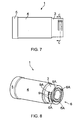
- FIGS 7 and 8 a second embodiment is illustrated of a silencer 1 and an attachment element 2 according to the present invention, where the silencer 1 and the attachment element 2 are interconnected.
- the silencer 1 comprises an attachment part 3, an intermediate part 4 and an outer muzzle part 5.
- the attachment part 3 comprises four cut-outs 6, where the cut-outs 6 are arranged in twos diametrically above one another.
- the cut-outs 6 furthermore do not pass through the material of the attachment part 3.
- the cut-outs 6 are composed of a portion 6A extending a distance in the silencer's 1 longitudinal direction and a portion 6B extending a distance over the inner circumference of the attachment part 3.
- the portions 6A, 6B are further connected by an intermediate part 6C, in order thereby to provide a J-shaped cut-out.
- At least one of the cut-outs 6 in the attachment part 3 will then be designed to achieve a releasable locking with a locking pin 7 in the attachment element 2.
- a slot 9 is provided which is designed to pass through the material of the attachment part 3.
- an additional slot 9 is provided above the cut-out 6, i.e. between the cut-out 6 and the attachment part's 3 end termination, where this slot 9 too is designed to pass through the material of the attachment part 3.
- the slots 9 are furthermore arranged adjacent to the portion 6B and extending parallel thereto.
- Yet another slot 9A is provided passing through the material of the attachment part 3, near one of the ends of the slots 9, where this slot 9A will extend from one slot 9 to the other slot 9.
- the slots 9, 9A will thus define a distance element 10, which distance element 10 will be flexible in the silencer's 1 radial direction.
- the distance element 10 will furthermore be provided with at least one bead 8, see also figure 9 , where this bead 8 is arranged on the inside of the distance element 10, extending radially into the silencer's 1 attachment part 3.
- the placing of the at least one bead 8 in the distance element 10 will create a radial narrowing of the portion 6B of the cut-out 6 which extends a distance over the inner circumference of the attachment part 3.
- FIG 9 an attachment element 2 according to the present invention is illustrated, where the attachment element 2 is intended to be capable of being releasably connected to a silencer 1 according to the present invention.
- Figure 9 illustrates a cross section (viewed from above) of figure 1 , where the cross section of the attachment part 3 is depicted with and without the attachment element 2.
- the attachment part 3 is provided with four cut-outs 6, where only the portion 6B of the cut-outs 6 extending a distance over the inner circumference of the attachment part 3 is shown.
- a slot 9A is provided, where these two portions 6B are located arranged diametrically above each other.
- the distance element 10 will be provided with a bead 8, where this bead 8 is arranged near the slot 9A.
- an attachment element 2, which in the illustrated embodiment comprises four locking pins 7, has to be connected to the silencer's 1 attachment part 3, the attachment element 2 will be arranged as illustrated on the left side of the figure (the locking pins 7 will then be mounted on the far right in the cut-outs 6).
- the silencer 1 will then be rotated clockwise, thereby bringing two of the locking pins 7 into contact with the beads 8 provided in the distance element 10.
- the beads 8 extend inwards in the radial direction of the attachment part 3, they will create a narrowing of the portion 6B of the cut-out 6, and an extra force must be exerted in order to rotate the silencer 1 past the locking pins 7. This extra force will cause the distance element 10 to be deflected slightly away and outwards from the silencer's 1 attachment part 3, thereby enabling the locking pins 7 to be moved past the beads 8. After the locking pins 7 have been moved past the beads 8, the distance element 10 will assume its original position, whereby the locking pins are locked in the portion 6B.
- the distance element 10 will be able to flex in the attachment part's 3 radial direction when a locking pin 7 is moved past the bead 8, whereupon the distance element 10 will be able to assume its original position when the locking pin 7 is moved past the bead 8.
- An opposite procedure is employed when the silencer 1 has to be released from the attachment element 2.
- the attachment element 2 according to the present invention is illustrated, where the attachment element 2 is designed to be capable of being mounted and/or connected to the barrel L of a firearm, for example by being provided with a threaded portion, or by being designed to be mounted a distance into the barrel's longitudinal direction, between an abutment shoulder on the barrel and a muzzle brake.
- the attachment element 2 comprises a casing element 21 with a flange part 22 which is provided with an outer flange 22A and an inner flange 22B, where the outer flange 22A is arranged to interact with an abutment shoulder 11 provided internally in the silencer's 1 attachment part 3, while the inner flange 22B is arranged to interact with an outer abutment surface (not shown) in the barrel L of a firearm.
- the outer flange 22A will then be provided with a diameter which is approximately equal to the attachment part's 3 internal diameter, while the inner flange 22B has a diameter which at least is approximately equal to a diameter of the barrel L of the firearm, at least over a part of the barrel's L length.
- the attachment element 2 is further provided with a number of locking pins 7 over its circumference, which locking pins 7 are designed to interact with a corresponding number of cut-outs 6 in the silencer's 1 attachment part 3.
Landscapes
- Engineering & Computer Science (AREA)
- General Engineering & Computer Science (AREA)
- Exhaust Silencers (AREA)
Description
- The present invention relates to a silencer for a firearm, such as a rifle or a pistol, where the silencer comprises a substantially cylindrical casing and where the silencer is intended to be releasably connected to an attachment element which is mounted on the barrel of the firearm.
- The present invention also relates to an attachment element which is intended to be releasably connected to a silencer according to the present invention.
- Silencers are used with high-pressure firearms in particular, since in many situations the report when the weapon is fired will be too loud. By means of its construction the silencer will be able to reduce the report and the recoil when shots are fired, thereby avoiding damage to hearing as well as making the marksman feel safer when firing a shot as the recoil is reduced.
- Known silencers are of a tubular design and may employ various principles in order to achieve a reduction of the report. We refer here, for example, to the American patents
US 5.029.512 andUS 4.907.488 . - In
US 5.029.512 the principle is employed of setting exhaust gases following the bullet in a rotating motion, thereby lowering the velocity of the exhaust gases before they leave the silencer. In this case, therefore, a number of elements will be arranged one behind the other internally in the cylindrical casing, where the elements interact in order to set the exhaust gases in rotation internally in the casing. - In
US 4.907.488 elements are also employed internally in a casing in order to change the direction of flow of the exhaust gases and thereby achieve a sound suppression. - The above silencers are designed to be able to be releasably connected to the barrel of the firearm. The silencer will then be provided with an internally threaded portion, where this threaded portion may either be arranged in the cylindrical casing or also arranged at an end of the silencer, which end will therefore form the silencer's attachment part. The firearm's barrel will then be provided with a corresponding and externally threaded portion over a part of its length, where this threaded portion may be provided at the end of the barrel or a distance into the barrel. The silencer will then be able to be screwed off and on to the firearm's barrel as required.
-
GB 24.766 -
US 5.559.302 A relates to a bayonet coupling for removably mounting accessories on an end of a gun barrel, wherein the gun barrel includes at least one lug spaced from the barrel end. A coupling adapter receives the gun barrel end and lugs and includes lug retaining recesses which receive the lugs upon relative rotation between the gun barrel and adapter occurring. A compressible spring located within the adapter biases an annular lug engaging sleeve wherein lug retention within the adapter recesses is maintained by the spring and only an axial movement of the adapter on the gun barrel is required to disengage the lug and its retaining recess to permit rotation of the adapter for quick adapter mounting and removal. - By means of the prior art, however, there will be a possibility that the silencer may be wrongly screwed on to the barrel of the firearm, whereby threads on the silencer and/or the barrel of the firearm could be destroyed. Furthermore, when handling the firearm under extreme conditions, sand, dirt etc. may infiltrate the threaded portion, with the result that it may be impossible to fit a silencer correctly or properly on to the barrel of the firearm. Finally, a problem could also arise with unscrewing the silencer when it has been mounted on the barrel of the firearm for a lengthy period.
- The object of the present invention is to provide a silencer which can be connected to and removed from a firearm's barrel in a simple and safe manner, and which consists of a small number of parts.
- This object is achieved according to the invention by means of the features indicated in the following independent claims, where further features of the invention will become apparent from the dependent claims and the description below.
- The present invention relates to a silencer for a firearm and an associated attachment element, where the silencer is designed to be able to be releasably connected to the attachment element which is mounted on the barrel of the firearm.
- A first embodiment of the silencer according to the present invention comprises a substantially cylindrical housing which is provided with an attachment part, an intermediate part and an outer muzzle part, where in the intermediate part a number of elements are arranged which will be capable of suppressing the sound of a report resulting from the firing of the weapon. The silencer is further designed to be releasably connected with an attachment element mounted on the barrel of a firearm, in which case the silencer's attachment part, i.e. the part of the silencer which has to be connected to the attachment element, is provided with a number of cut-outs round its circumference, where each cut-out is composed of a portion extending a distance in the silencer's longitudinal direction and a portion extending a distance over the circumference of the attachment part, which two portions are connected with an intermediate portion. In the portion which extends a distance over the circumference of the attachment part, at least one of the cut-outs is provided with at least one bead, in order thereby to create a narrowing of the portion of the cut-out extending a distance over the circumference of the attachment part, where adjacent to this portion at least one additional slot is provided extending over the circumference of the attachment part.
- In this embodiment of the silencer, therefore, the cut-outs will be provided passing through the material of the attachment part.
- In an embodiment of the invention the at least one slot which is arranged adjacent to the portion of the cut-out provided with at least one bead will be designed to have the same length as the adjacent portion, in which case the slot will have a width or height which is less than the width of the adjacent portion with the bead. It should be understood, however, that the slot may be designed to have other lengths and/or widths. The slot, moreover, is preferably arranged between the silencer's intermediate part and the portion with the bead, but may also be arranged on an opposite side of the portion with the bead, or on both sides of the portion with the bead.
- The slot may furthermore extend parallel to the portion with the bead, and the slot may also be composed of several smaller holes, partial slots etc. arranged one behind the other, where these will have the same function as the slot.
- Together with the portion of the cut-out which is provided with at least one bead according to the present invention, the slot will act as a spring element, as the slot and the portion with the bead will be separated by a distance element with relatively little width or height in accordance with the design of the cut-out and the slot, where this distance element will then be permitted to be moved in the silencer's longitudinal direction when by means of the attachment part the silencer has to be connected to an attachment element which is mounted on the firearm's barrel, since the attachment element is provided with a number of locking pins corresponding to the cut-outs with which the silencer's attachment part is provided.
- The assembly of the silencer and the attachment element and the function of the distance element will be explained in greater detail below.
- The intermediate portion connecting the portion of the cut-out which extends a distance in the silencer's longitudinal direction and the portion of the cut-out which extends a distance over the circumference of the attachment part, in order thereby to form the cut-out, may be provided at least over a part of its length with a straight piece, where this straight piece is arranged so as to form an angle with both the portion of the cut-out which extends a distance in the silencer's longitudinal direction and the portion of the cut-out which extends a distance over the circumference of the attachment part. This design of the cut-out will provide a force which will help to separate the silencer and the attachment element when the silencer has to be released from the attachment element, since on account of the design of the intermediate portion, the locking pins in the attachment element will be forced out of engagement with the portion of the cut-out which extends a distance over the circumference of the attachment part when the silencer is screwed about its longitudinal direction, with the result that the locking pins are inserted in the portion which extends a distance in the silencer's longitudinal direction. In a similar manner the intermediate portion's design will force the locking pins into engagement with the portion of the cut-out which extends a distance over the circumference of the attachment part when the silencer has to be connected to the attachment element which is mounted on the barrel of the firearm.
- In an embodiment of the present invention the silencer's attachment part is provided with four cut-outs which are arranged at an equal distance apart, for example located at 90 degrees apart from one another, and where two of these cut-outs are provided with a bead. Adjacent to each of these cut-outs with bead there is also provided a slot extending over the circumference of the attachment part. It should be understood, however, that the attachment part may also be provided with a greater or smaller number of cut-outs, for example three, where the cut-outs may be arranged at an equal or unequal distance relative to one another, and where fewer or all the cut-outs may be provided with a bead. Furthermore it should be understood that several beads may also be provided in this portion. In this embodiment the two other cut-outs will then be provided with an intermediate portion which is provided over at least a part of its length with a straight piece, with the result that these two cut-outs will produce a force which will provide help when silencer and attachment element have to be connected or released.
- In an alternative embodiment of the silencer according to the present invention the silencer's attachment part is provided with three cut-outs which are arranged at 120 degrees relative to one another. In this embodiment a cut-out may, for example, be provided with at least one bead, and where adjacent to this cut-out a slot is provided extending over the circumference of the attachment part, while two cut-outs will then be provided with an intermediate portion which is provided over at least a part of its length with a straight piece, with the result that these two cut-outs will produce a force which will provide help when silencer and attachment element have to be connected or released.
- The cut-outs have a J or L-shape, but may also have other geometrical shapes which will enable a releasable locking to be achieved between the silencer and the attachment element.
- The at least one bead which is provided in the portion of the cut-out extending a distance over the circumference of the attachment part is arranged located outside the portion extending a distance in the silencer's longitudinal direction. The at least one bead will furthermore extend into the portion of the cut-out which extends a distance over the circumference of the attachment part, with the result that the at least one bead will create a narrowing of this portion.
- It should be understood that the portion of the cut-out which extends a distance over the circumference of the attachment part may be provided with several beads arranged behind one another, where the bead or beads may have a geometry which results in the need to apply an extra force in order to move the attachment element's locking pins past the bead or beads.
- If several beads are provided in the portion of the cut-out which extends a distance over the circumference of the attachment part, the beads may have the same or different geometry and/or dimensions.
- When the silencer according to the present invention has to be connected to the attachment element mounted on the firearm's barrel, the silencer will be inserted towards the attachment element's locking pins, so that the locking pins are inserted into the portions of the cut-outs which extend a distance in the silencer's longitudinal direction. When the locking pins have come into contact with the intermediate portion of the cut-out, the silencer will begin to be rotated about its longitudinal axis, whereby this rotation will cause the straight piece in the intermediate portion of the cut-out to force the locking pins into engagement with the portion of the cut-out extending a distance over the circumference of the attachment part. After the locking pins have been inserted a distance into the portion of the cut-out extending a distance in the circumference of the attachment part, at least one of the locking pins will be brought into contact with the at least one bead. By means of a further rotation of the silencer, the locking pin will be brought past the bead, since by means of this rotation the distance element will be deflected in towards the adjacent slot, thereby enabling the locking pin to be moved past the bead. When the locking pin has been moved past the bead, the distance element will assume its original position again, thereby locking the locking pin in the cut-out. By means of this design of the cut-out(s) and slot(s) the distance element will be able to flex in the silencer's longitudinal direction when a locking pin is moved past the bead(s), whereupon the distance element will assume its original position when the locking pin has been moved past the bead(s).
- In an alternative embodiment of the silencer according to the present invention the distance element is designed to be able to flex in the silencer's radial direction. The silencer's attachment part will then be provided in a similar manner to that indicated above with a number of cut-outs, slots, etc., but in this case the cut-outs will not be designed to pass through the material of the attachment part. In this alternative embodiment, moreover, at least two slots will be provided adjacent to the portion of the non-through-going cut-out which extends a distance over the circumference of the attachment part, where one of the slots is arranged between the silencer's intermediate part and the portion extending a distance over the circumference of the attachment part, and where the second slot is arranged between the portion extending a distance over the circumference of the attachment part and the attachment part's end termination, with the result that the slots are arranged on each side of the portion extending a distance over the circumference of the attachment part. Near one of the ends of the slots an additional slot is further provided, where this slot will extend over both the slots. Between them, the three slots will therefore form a distance element, which distance element will be flexible in the silencer's radial direction. This distance element will then be provided with at least one bead, where this bead is arranged on the inside of the distance element, extending radially into the silencer, in order thereby to create a radial narrowing of the portion of the cut-out which extends a distance over the circumference of the attachment part.
- It will be appreciated that, with the exception of the cut-outs, which are designed not to pass through the material of the attachment part, and the distance element which is designed to provide a radial flexibility, this embodiment of the silencer could otherwise be designed in a similar manner to that indicated with regard to the first embodiment of the silencer.
- The assembly of the silencer and the attachment element will also be accomplished as explained above with regard to the first embodiment of the silencer, except for the fact that the distance element will now be radially flexible.
- The present invention also relates to an attachment element for a silencer, where the attachment element is designed to be able to be mounted on the barrel of a firearm. The attachment element comprises a casing element with a flange part which is provided with an outer and inner flange, where the outer flange is arranged to interact with an abutment shoulder in a silencer's attachment part, while the inner flange is arranged to interact with an outer abutment surface in the barrel of a firearm. The outer flange will then be provided with a diameter which is approximately equal to the attachment part's internal diameter, while the inner flange has a diameter which at least is approximately equal to a diameter of the barrel of the firearm, at least over a part of the barrel's length. The attachment element is further provided with a number of locking pins over its circumference, which locking pins are designed to interact with a corresponding number of cut-outs in the silencer's attachment part.
- In an embodiment of the attachment element the locking pins are designed to have a length which will be flush with an outer diameter of the silencer's attachment part when the silencer is connected with the attachment element. It should be understood, however, that the locking pins may be designed to have other lengths, where the locking pins furthermore may have the same or different length, thickness etc.
- The attachment element according to the present invention could be an independent element which is designed to be mounted in a suitable manner on a firearm's barrel, for example by being provided with threads, thereby enabling the attachment element to be screwed on to the firearm's barrel, or the attachment element may be designed to be able to be mounted between the firearm's barrel and a flash eliminator, muzzle brake or the like. The attachment element may also be integrated in the firearm's barrel, flash eliminator, muzzle brake or the like.
- Further objects, structural embodiments and advantages of the present invention will be clearly shown in the following detailed description, the attached drawings and the following claims.
- The invention will now be explained with reference to the attached figures in which;
-
Figure 1 illustrates an embodiment of a silencer connected to an attachment element according to the present invention, -
Figure 2 illustrates the silencer and the attachment element infigure 1 partially viewed from the side, -
Figure 3 illustrates in greater detail the design of the silencer's attachment part, -
Figure 4 illustrates a longitudinal cross section of the silencer and the attachment element infigure 1 , -
Figure 5 illustrates the silencer and the attachment element viewed from above, -
Figure 6 illustrates the attachment element according to the present invention viewed from above, from the side and partially viewed from the side, -
Figure 7 illustrates a second embodiment of a silencer connected with an attachment element according to the present invention, -
Figure 8 illustrates the silencer and the attachment element infigure 7 partially viewed from the side, -
Figure 9 illustrates a cross section from above, where the cross section is shown both with and without the attachment element, -
Figure 10 illustrates a longitudinal cross section of the silencer and the attachment element infigure 7 , and -
Figure 11 illustrates the attachment element according to the present invention viewed from above, from the side and partially viewed from the side. - In
figure 1 a first embodiment is illustrated of asilencer 1 and anattachment element 2 according to the present invention depicted connected to each other, where thesilencer 1 comprises anattachment part 3, anintermediate part 4 and anouter muzzle part 5. - In the
intermediate part 4 of the silencer (1) a number of elements E are mounted which will be capable of suppressing the sound of a report produced during firing of a weapon (not shown). A person skilled in the art will know what constitutes the elements E and how they should be constructed, and therefore this will not be discussed further here. - In the illustrated embodiment the silencer's (1)
attachment part 3 is provided with four cut-outs 6, the cut-outs 6 being arranged in twos diametrically above one another. The cut-outs 6 are composed of aportion 6A which extends a distance in the silencer's 1 longitudinal direction and aportion 6B which extends a distance over the circumference of theattachment part 3. Theportions intermediate portion 6C, in order thereby to provide a J-shaped cut-out. At least one cut-out 6 in theattachment part 3, see the lower part offigure 1 , will be designed to achieve a releasable locking with alocking pin 7 in theattachment element 2. This cut-out 6 will then be provided with aportion 6B which extends a longer distance over the circumference of theattachment part 3 than the other cut-outs 6, see alsofigure 3 . In theportion 6B, moreover, abead 8 is provided, where thisbead 8 is arranged in an area of theportion 6B located outside theintermediate portion 6C and theportion 6A of the cut-out 6. Thebead 8 will furthermore extend into theportion 6B, so that thebead 8 creates a narrowing of theportion 6B. Below theportion 6B of this cut-out 6, i.e. between the cut-out 6 and the silencer's 1intermediate part 4, aslot 9 is provided, where theslot 9 extends parallel to theintermediate portion 6C and theportion 6B of the cut-out 6. Theslot 9 and theportions distance element 10, which is provided with thebead 8, where theportion 6B, thedistance element 10 and theslot 9 will interact in order to achieve a releasable connection between thesilencer 1 and theattachment element 2. This will be explained in more detail below. - The other cut-
outs 6 in the silencer's 1attachment part 3 will then be designed like the cut-out 6 as illustrated in the upper part offigure 1 ; in a similar manner, the cut-out 6 shown here will comprise aportion 6A extending a distance in the silencer's 1 longitudinal direction and aportion 6B extending a distance over the circumference of theattachment part 3, where theportions intermediate portion 6C, in order thereby to form a J-shaped cut-out. Over a part of its length theintermediate portion 6C is provided with astraight piece 6C1, where thisstraight piece 6C1 then forms an angle with both theportions portion 6C1 will provide a force which will help to separatesilencer 1 andattachment element 2 when thesilencer 1 has to be separated from theattachment element 2, since, on account of thestraight piece 6C1, the locking pins 7 in theattachment element 2 will be forced out of engagement with theportion 6B when thesilencer 1 is rotated about its longitudinal direction, with the result that the locking pins 7 are guided into theportion 6A in the cut-out 6. Correspondingly, thestraight portion 6C1 will force the locking pins 7 into engagement with theportion 6B when thesilencer 1 has to be connected to theattachment element 2 mounted on the barrel L of a firearm. - As indicated above the
silencer 1 illustrated infigure 1 is provided with four cut-outs 6, where two of the cut-outs 6 are provided with abead 8 and an adjacent slot 9 (shown in the lower part offigure 1 ), while the two remaining cut-outs 6 are provided with thestraight piece 6C1 in theintermediate portion 6C (shown in the upper part offigure 1 ). - The
attachment element 2, see alsofigure 6 , according to the present invention is designed to be able to be mounted and/or connected to the barrel L of a firearm, for example by being provided with a threaded portion, or by being designed to be mounted a distance into the barrel's longitudinal direction, between an abutment shoulder on the barrel and a muzzle brake. Theattachment element 2 comprises acasing element 21 with aflange part 22 which is provided with anouter flange 22A and aninner flange 22B, where theouter flange 22A is arranged to interact with anabutment shoulder 11 provided internally in the silencer's 1attachment part 3, while theinner flange 22B is arranged to interact with an outer abutment surface (not shown) in the barrel L of a firearm. Theouter flange 22A will then be provided with a diameter which is approximately equal to the attachment part's 3 internal diameter, while theinner flange 22B has a diameter which is at least approximately equal to a diameter of the barrel L of the firearm, at least over a part of the barrel's L length. Theattachment element 2 is further provided with a number oflocking pins 7 over its circumference, which locking pins 7 are designed to interact with a corresponding number of cut-outs 6 in the silencer's 1attachment part 3. - When the
silencer 1 according to the present invention has to be connected to theattachment element 2 according to the present invention, where theattachment element 2 is mounted on the barrel L of the firearm, the silencer's 1attachment part 3 will be inserted in towards the attachment element's 2 locking pins 7, so that the locking pins 7 are inserted inportions 6A of the cut-outs 6. When the locking pins 7 have come into contact with theintermediate portion 6C of the cut-outs 6, thesilencer 1 will begin to be rotated about its longitudinal axis, whereby this rotation will cause thestraight piece 6C1 in theintermediate portion 6C of the cut-out 6 to force the locking pins 7 into engagement with theportion 6B of the cut-outs 6. After the locking pins 7 have been inserted a distance into theportions 6B of the cut-outs 6, two of the locking pins 7 will be brought into contact with thebeads 8 which are provided in theseportions 6B. On further rotation of thesilencer 1, the locking pins 7 will be brought past thebeads 8, since by means of this rotation thedistance elements 10 will be deflected in towards theadjacent slots 9, thereby enabling the locking pins 7 to be moved past thebeads 8. When the locking pins 7 have been moved past thebeads 8, thedistance elements 10 will assume their original position again, whereby the locking pins 7 are locked in the cut-outs 6. By means of this design of the cut-out(s) 6 and slot(s) 9, thedistance element 10 will be able to flex in the silencer's 1 longitudinal direction when alocking pin 7 is moved past the bead(s) 8, whereupon thedistance element 10 will assume its original position when the locking pins 7 are moved past the bead(s) 8. - In
figures 7 and 8 a second embodiment is illustrated of asilencer 1 and anattachment element 2 according to the present invention, where thesilencer 1 and theattachment element 2 are interconnected. Thesilencer 1 comprises anattachment part 3, anintermediate part 4 and anouter muzzle part 5. - The
attachment part 3 comprises four cut-outs 6, where the cut-outs 6 are arranged in twos diametrically above one another. The cut-outs 6 furthermore do not pass through the material of theattachment part 3. The cut-outs 6 are composed of aportion 6A extending a distance in the silencer's 1 longitudinal direction and aportion 6B extending a distance over the inner circumference of theattachment part 3. Theportions intermediate part 6C, in order thereby to provide a J-shaped cut-out. At least one of the cut-outs 6 in theattachment part 3 will then be designed to achieve a releasable locking with alocking pin 7 in theattachment element 2. In connection with this cut-out 6, below the cut-out 6, i.e. between the cut-out 6 and the silencer's 1intermediate part 4, aslot 9 is provided which is designed to pass through the material of theattachment part 3. In a similar manner anadditional slot 9 is provided above the cut-out 6, i.e. between the cut-out 6 and the attachment part's 3 end termination, where thisslot 9 too is designed to pass through the material of theattachment part 3. Theslots 9 are furthermore arranged adjacent to theportion 6B and extending parallel thereto. - Yet another
slot 9A is provided passing through the material of theattachment part 3, near one of the ends of theslots 9, where thisslot 9A will extend from oneslot 9 to theother slot 9. Theslots distance element 10, whichdistance element 10 will be flexible in the silencer's 1 radial direction. Thedistance element 10 will furthermore be provided with at least onebead 8, see alsofigure 9 , where thisbead 8 is arranged on the inside of thedistance element 10, extending radially into the silencer's 1attachment part 3. The placing of the at least onebead 8 in thedistance element 10 will create a radial narrowing of theportion 6B of the cut-out 6 which extends a distance over the inner circumference of theattachment part 3. - The other cut-
outs 6 will then be provided without theslots bead 8. - The releasable connection of the
silencer 1 and theattachment element 2, and the function of thedistance element 10 will be explained in more detail below. - In
figure 9 anattachment element 2 according to the present invention is illustrated, where theattachment element 2 is intended to be capable of being releasably connected to asilencer 1 according to the present invention.Figure 9 illustrates a cross section (viewed from above) offigure 1 , where the cross section of theattachment part 3 is depicted with and without theattachment element 2. Here it can be seen that theattachment part 3 is provided with four cut-outs 6, where only theportion 6B of the cut-outs 6 extending a distance over the inner circumference of theattachment part 3 is shown. It is further illustrated in the figure that in connection with two of theportions 6B aslot 9A is provided, where these twoportions 6B are located arranged diametrically above each other. Thedistance element 10 will be provided with abead 8, where thisbead 8 is arranged near theslot 9A. When anattachment element 2, which in the illustrated embodiment comprises four lockingpins 7, has to be connected to the silencer's 1attachment part 3, theattachment element 2 will be arranged as illustrated on the left side of the figure (the locking pins 7 will then be mounted on the far right in the cut-outs 6). Thesilencer 1 will then be rotated clockwise, thereby bringing two of the locking pins 7 into contact with thebeads 8 provided in thedistance element 10. Since thebeads 8 extend inwards in the radial direction of theattachment part 3, they will create a narrowing of theportion 6B of the cut-out 6, and an extra force must be exerted in order to rotate thesilencer 1 past the locking pins 7. This extra force will cause thedistance element 10 to be deflected slightly away and outwards from the silencer's 1attachment part 3, thereby enabling the locking pins 7 to be moved past thebeads 8. After the locking pins 7 have been moved past thebeads 8, thedistance element 10 will assume its original position, whereby the locking pins are locked in theportion 6B. By means of this design of the cut-outs 6, theslots beads 8, thedistance element 10 will be able to flex in the attachment part's 3 radial direction when alocking pin 7 is moved past thebead 8, whereupon thedistance element 10 will be able to assume its original position when thelocking pin 7 is moved past thebead 8. An opposite procedure is employed when thesilencer 1 has to be released from theattachment element 2. - In
figure 10 theattachment element 2 according to the present invention is illustrated, where theattachment element 2 is designed to be capable of being mounted and/or connected to the barrel L of a firearm, for example by being provided with a threaded portion, or by being designed to be mounted a distance into the barrel's longitudinal direction, between an abutment shoulder on the barrel and a muzzle brake. Theattachment element 2 comprises acasing element 21 with aflange part 22 which is provided with anouter flange 22A and aninner flange 22B, where theouter flange 22A is arranged to interact with anabutment shoulder 11 provided internally in the silencer's 1attachment part 3, while theinner flange 22B is arranged to interact with an outer abutment surface (not shown) in the barrel L of a firearm. Theouter flange 22A will then be provided with a diameter which is approximately equal to the attachment part's 3 internal diameter, while theinner flange 22B has a diameter which at least is approximately equal to a diameter of the barrel L of the firearm, at least over a part of the barrel's L length. Theattachment element 2 is further provided with a number oflocking pins 7 over its circumference, which locking pins 7 are designed to interact with a corresponding number of cut-outs 6 in the silencer's 1attachment part 3. - The present invention has now been explained with reference to embodiments, but a person skilled in the art will appreciate that changes and modifications will be able to be made to these embodiments which lie within the scope of the invention as defined in the following claims.
Claims (13)
- A silencer (1) for a firearm comprising a substantially cylindrical external housing comprising an attachment part (3), an intermediate part (4) comprising a number of elements and an outer muzzle part (5), which silencer (1) can be releasably connected to a firearm's barrel, where the attachment part (4) is provided with a number of cut-outs (6) round its circumference, which cut-outs (6) are composed of a portion (6A) extending a distance in the silencer's (1) longitudinal direction and a portion (6B) extending a distance over the circumference of the attachment part (3), which two portions (6A, 6B) are connected with an intermediate portion (6C), where at least one cut-out (6) in the portion (6B) extending a distance over the circumference of the attachment part (3) is narrowed by at least one bead (8), and where adjacent to this portion (6B) at least one slot (9) is provided extending over the circumference of the attachment part (3).
- A silencer according to claim 1,
characterised in that at least one slot (9) and the adjacent portion (6B) with the bead (8) have the same length. - A silencer according to claim 2,
characterised in that the at least one slot (9) has a width which is less than the width of the adjacent portion (6B) with the bead (8). - A silencer according to any of the preceding claims,
characterised in that in at least one of the cut-outs (6) the intermediate portion (6C) is at least over a part of its length provided with a straight piece (6C1), forming an angle with both the portion (6A) which extends a distance in the silencer's (1) longitudinal direction and the portion (6B) which extends a distance over the circumference of the attachment part (3). - A silencer according to claim 1 or 2,
characterised in that the bead (8) in the portion (6B) which extends a distance over the circumference of the attachment part (3) is arranged in an area located outside the portion (6A) which extends a distance in the silencer's (1) longitudinal direction. - A silencer according to claim 1,
characterised in that the attachment part (3) is provided on an inside with an abutment shoulder (11), which abutment shoulder (11) is arranged below the at least one slot (9). - A silencer according to claim 1,
characterised in that the portion (6B) which extends a distance over the circumference of the attachment part (3) at an end opposite the intermediate portion (6C) is in the form of a semicircle. - A silencer according to claim 1,
characterised in that the attachment part (3) is provided on the inside with a number of slots, which slots are arranged adjacent to and on each side of the portion (6B) which extends a distance over the circumference of the attachment part (3). - A silencer according to claim 1 or 2,
characterised in that the at least one bead (8) faces into the portion (6B) of the cut-out which extends a distance over the circumference of the attachment part (3), thereby creating a narrowing in this portion (6B) of the cut-out (6). - A silencer according to claim 1, 2 or 9,
characterised in that the portion (6B) of the cut-out which extends a distance over the circumference of the attachment part (3) is provided with a plurality of beads (8) with the same or different dimensions. - An attachment element (2) for a silencer according to any of the preceding claims 1-10, the attachment element (2) comprising a casing element (21) comprising a flange part (22) provided with an outer and inner flange (22A, 22B), which outer flange (22A) is arranged to interact with an internal abutment shoulder (11) in the silencer's (1) attachment part (3), and which inner flange (22B) is arranged to interact with an external abutment surface in a firearm's barrel, where the outer flange (22A) has a diameter approximately equal to the attachment part's (3) internal diameter and where the inner flange (22B) has a diameter at least approximately equal to a part of the barrel's outer diameter where the attachment element (2) is further provided with a number of locking pins (7) over its circumference, which locking pins (7) are designed to interact with a corresponding number of cut-outs (6) in the silencer's (1) attachment part (3).
- An attachment element according to claim 11,
characterised in that the locking pins (7) will be level with an external diameter of the silencer's (1) attachment part (3) when a silencer (1) is connected to the attachment element (2). - An attachment element according to claim 11,
characterised in that on a rotation of a silencer (1), the locking pins (7) are arranged to be brought into contact with a number of cut-outs provided on the inside of an attachment part (3).
Applications Claiming Priority (2)
| Application Number | Priority Date | Filing Date | Title |
|---|---|---|---|
| NO20111648A NO333615B1 (en) | 2011-11-29 | 2011-11-29 | Muffler for weapons |
| PCT/EP2012/073733 WO2013079483A1 (en) | 2011-11-29 | 2012-11-27 | Silencer for a firearm |
Publications (2)
| Publication Number | Publication Date |
|---|---|
| EP2786087A1 EP2786087A1 (en) | 2014-10-08 |
| EP2786087B1 true EP2786087B1 (en) | 2016-09-14 |
Family
ID=47471701
Family Applications (1)
| Application Number | Title | Priority Date | Filing Date |
|---|---|---|---|
| EP12809133.7A Active EP2786087B1 (en) | 2011-11-29 | 2012-11-27 | Silencer for a firearm |
Country Status (6)
| Country | Link |
|---|---|
| US (1) | US8714300B2 (en) |
| EP (1) | EP2786087B1 (en) |
| KR (1) | KR20140116855A (en) |
| CA (1) | CA2855268C (en) |
| NO (1) | NO333615B1 (en) |
| WO (1) | WO2013079483A1 (en) |
Cited By (1)
| Publication number | Priority date | Publication date | Assignee | Title |
|---|---|---|---|---|
| EP4400799A1 (en) * | 2023-01-11 | 2024-07-17 | Shadow Systems, LLC | Quick-connect muzzle accessory |
Families Citing this family (38)
| Publication number | Priority date | Publication date | Assignee | Title |
|---|---|---|---|---|
| US20160161203A1 (en) | 2012-12-21 | 2016-06-09 | Bert John WILSON | Suppressors and their methods of manufacture |
| US9658019B2 (en) | 2014-09-19 | 2017-05-23 | Ra Brands, L.L.C. | Silencer and mounting system |
| US10184744B2 (en) | 2014-10-08 | 2019-01-22 | Smith & Wesson Corp. | Quick connect for pistol suppressor |
| US10088261B1 (en) * | 2015-11-30 | 2018-10-02 | Paul A. Oglesby | Blast mitigation device |
| US9921021B1 (en) * | 2015-12-29 | 2018-03-20 | Rugged Design, Inc. | Firearm attachment locking systems and methods |
| US10753700B2 (en) * | 2016-01-15 | 2020-08-25 | ZEV Technologies, Inc. | Firearm accessory mounting system |
| US11441867B2 (en) * | 2016-03-25 | 2022-09-13 | Sound Moderation Techoologies. LLC | Silencer mount |
| US9513078B1 (en) * | 2016-05-17 | 2016-12-06 | Precision Tooling Products, LLC | Quick mount firearm barrel accessory |
| US10619964B2 (en) * | 2017-01-11 | 2020-04-14 | Palmetto State Armory, LLC | Modified pistol upper |
| US10641573B2 (en) * | 2017-02-27 | 2020-05-05 | Strike Industries, Inc. | Lock mechanism for muzzle shroud and blast diffuser using the same |
| US10156411B2 (en) * | 2017-04-06 | 2018-12-18 | Daniel Defense, Inc. | Systems and methods for coupling suppressors or other muzzle end barrel devices to firearms |
| US10119779B1 (en) | 2017-06-27 | 2018-11-06 | Smith & Wesson Corp. | Suppressor for firearm and baffle cup therefor |
| US11255624B2 (en) * | 2017-10-12 | 2022-02-22 | Jason McRorey | Muzzle adaptation system |
| US10488139B1 (en) | 2018-01-19 | 2019-11-26 | Rugged Design, Inc. | Method and apparatuses for attaching devices to firearm |
| US10890402B2 (en) * | 2018-01-23 | 2021-01-12 | American Defense Manufacturing, Llc | Firearm suppressor system and associated quick release mount and lock |
| DK3514475T3 (en) * | 2018-01-23 | 2021-07-26 | A Tec Holding As | CONNECTION ELEMENT |
| US11054208B2 (en) | 2018-01-23 | 2021-07-06 | A-Tec Holding As | Apparatus for fastening a device onto a barrel of a firearm |
| US20200224989A1 (en) * | 2018-10-05 | 2020-07-16 | Maxim Defense Industries, LLC | Apparatus and method for resonance modulation of firearm discharge gases |
| US11530890B2 (en) | 2018-12-10 | 2022-12-20 | Maxim Defense Industries, LLC | Apparatus and method for regulating firearm discharge gases and mounting a component to a firearm |
| US10845149B2 (en) * | 2019-03-08 | 2020-11-24 | John Anthony Doerr | Silencer for gun |
| NO344916B1 (en) * | 2019-03-22 | 2020-06-29 | A Tec Holding As | Silencer |
| EP3835706B1 (en) * | 2019-12-13 | 2023-10-18 | Glock Technology GmbH | Adapter for mounting an accessory to a firearm |
| US11486670B1 (en) * | 2020-04-23 | 2022-11-01 | Seraph Enterprises, Inc. | Quick disconnect system for muzzle devices |
| US20210404760A1 (en) * | 2020-06-02 | 2021-12-30 | Aaron Hipp | Adjustable tuning device |
| US12253329B2 (en) * | 2020-12-17 | 2025-03-18 | James Matthew Underwood | Handguard |
| CN113251853B (en) * | 2021-06-11 | 2023-01-06 | 青岛哈船海厚机电技术有限责任公司 | Rifle bore locking device for preventing misoperation and special wrench |
| US12449219B2 (en) | 2021-08-30 | 2025-10-21 | Maxim Defense Industries, LLC | Firearm suppressor and self-torquing feature |
| USD1069018S1 (en) | 2021-10-25 | 2025-04-01 | Maxim Defense Industries, LLC | Firearm suppressor core |
| USD1020965S1 (en) | 2021-10-25 | 2024-04-02 | Maxim Defense Industries, LLC | Combined firearm suppressor core and tube |
| US12320605B2 (en) | 2021-11-02 | 2025-06-03 | Bert John WILSON | Connector for a firearm accessory |
| USD1057070S1 (en) | 2022-01-14 | 2025-01-07 | Maxim Defense Industries, LLC | Firearm suppressor core |
| USD1035816S1 (en) | 2022-01-14 | 2024-07-16 | Maxim Defense Industries, LLC | Combined firearm suppressor core, mount body, tube, and spring |
| USD1050337S1 (en) | 2022-01-14 | 2024-11-05 | Maxim Defense Industries, LLC | Combined firearm suppressor core, mount body, tube, and spring |
| US12298096B2 (en) | 2022-01-14 | 2025-05-13 | Maxim Defense Industries, LLC | Firearm suppressor assembly, and apparatus and method for audible signature reduction of a firearm |
| USD1080791S1 (en) | 2022-01-14 | 2025-06-24 | Maxim Defense Industries, LLC | Firearm suppressor core |
| USD1036611S1 (en) | 2022-01-14 | 2024-07-23 | Maxim Defense Industries, LLC | Combined firearm suppressor core, mount body, and tube |
| WO2023137242A1 (en) | 2022-01-16 | 2023-07-20 | Shadow Systems, LLC | Firearm muzzle accessory |
| US12546551B2 (en) * | 2024-03-26 | 2026-02-10 | Killer Innovations, Inc. | Muzzle assembly for a firearm |
Family Cites Families (18)
| Publication number | Priority date | Publication date | Assignee | Title |
|---|---|---|---|---|
| US968583A (en) | 1909-08-12 | 1910-08-30 | Onesime E Michaud | Attachment for shotguns. |
| CH48989A (en) * | 1910-10-25 | 1910-12-16 | Eugene Thurler | Apparatus for suppressing the detonation of firearms |
| GB191124766A (en) | 1911-11-07 | 1912-04-18 | George Albert Williams | Improvements in or relating to Closures for Bottles and Caps therefor. |
| US1354416A (en) | 1919-10-21 | 1920-09-28 | Oliver Stacy | Silencer-coupling |
| US4907488A (en) | 1988-03-29 | 1990-03-13 | Seberger Oswald P | Device for silencing firearms and cannon |
| US4893426A (en) * | 1988-10-07 | 1990-01-16 | South Central Research Corp. | Lugged coupling apparatus |
| US5029512A (en) | 1990-04-16 | 1991-07-09 | Latka Gregory S | Firearm muzzle silencer |
| FI91918C (en) | 1992-03-23 | 1994-08-25 | Sampo Karppinen | Quick attachment piece for bayonet attachment of a silencer for a weapon |
| US5433133A (en) | 1994-03-07 | 1995-07-18 | La France; Timothy F. | Quick detachable gun barrel coupling member |
| US5559302A (en) * | 1995-08-31 | 1996-09-24 | Gsl Technology, Inc. | Bayonet type coupling for firearms |
| DE10001374C1 (en) * | 2000-01-14 | 2001-06-21 | Heckler & Koch Gmbh | Retainer for fixture of silencer on barrel of hand gun has part rotatable relatively to barrel around bore axis and non-rotatable part |
| US7676976B2 (en) * | 2003-11-06 | 2010-03-16 | Surefire, Llc | Systems for attaching a noise suppressor to a firearm |
| US7516690B2 (en) * | 2006-12-22 | 2009-04-14 | Mcclellan W Thomas | Firearm suppressor, mounting system and mounting method |
| US7789009B1 (en) * | 2007-02-08 | 2010-09-07 | Advanced Armament Corp., Llc | Omni indexing mount primarily for attaching a noise suppressor or other auxiliary device to a firearm |
| US7743693B1 (en) * | 2007-02-28 | 2010-06-29 | Advanced Armament Corp., Llc | Redundant latch suppressor mount |
| US7905170B1 (en) * | 2007-07-18 | 2011-03-15 | Advanced Armament Corp., Llc | Flash suppressor |
| US20090193963A1 (en) * | 2007-09-11 | 2009-08-06 | Poulsen Peter Ostergaard | Joint between a sound suppressor and a barrel of a firearm |
| US7891282B1 (en) * | 2008-07-23 | 2011-02-22 | Advanced Armament Corp. | Booster for handgun silencers |
-
2011
- 2011-11-29 NO NO20111648A patent/NO333615B1/en unknown
-
2012
- 2012-11-27 EP EP12809133.7A patent/EP2786087B1/en active Active
- 2012-11-27 KR KR1020147018184A patent/KR20140116855A/en not_active Withdrawn
- 2012-11-27 WO PCT/EP2012/073733 patent/WO2013079483A1/en not_active Ceased
- 2012-11-27 CA CA2855268A patent/CA2855268C/en active Active
- 2012-11-29 US US13/689,333 patent/US8714300B2/en active Active
Cited By (1)
| Publication number | Priority date | Publication date | Assignee | Title |
|---|---|---|---|---|
| EP4400799A1 (en) * | 2023-01-11 | 2024-07-17 | Shadow Systems, LLC | Quick-connect muzzle accessory |
Also Published As
| Publication number | Publication date |
|---|---|
| KR20140116855A (en) | 2014-10-06 |
| NO20111648A1 (en) | 2013-05-30 |
| CA2855268C (en) | 2017-04-18 |
| US20130133976A1 (en) | 2013-05-30 |
| US8714300B2 (en) | 2014-05-06 |
| WO2013079483A1 (en) | 2013-06-06 |
| NO333615B1 (en) | 2013-07-22 |
| EP2786087A1 (en) | 2014-10-08 |
| CA2855268A1 (en) | 2013-06-06 |
Similar Documents
| Publication | Publication Date | Title |
|---|---|---|
| CA2855268C (en) | Silencer for a firearm | |
| EP3705835B1 (en) | A coupling | |
| US9464857B2 (en) | Sound suppressor for a firearm | |
| US7353740B1 (en) | Rapid adjust muzzle system | |
| EP2805125B1 (en) | Firearm noise suppressor system | |
| JP4234462B2 (en) | Gun barrel with muzzle control | |
| US10234229B2 (en) | Muzzle end accessory mount for a firearm | |
| US8439155B2 (en) | Firearm sound suppressor | |
| US9921019B2 (en) | Gas vent for firearm | |
| US20180106569A1 (en) | Silencer mount system for firearms | |
| US9541344B2 (en) | Firearm compensator assembly | |
| US11054208B2 (en) | Apparatus for fastening a device onto a barrel of a firearm | |
| US20180340749A1 (en) | Noise Suppressor for Firearm and Blank Firing Adapter for Firearm | |
| US9921020B2 (en) | Sound suppressor with replaceable components | |
| US9297600B1 (en) | Firearm choke tube | |
| WO2019113591A1 (en) | Concentric rifle barrel assembly | |
| US20230296344A1 (en) | Firearm suppressor with secondary retention system | |
| EP3514475B1 (en) | A coupling member | |
| US20160349000A1 (en) | Multi-barrel system and apparatus | |
| RU2302602C1 (en) | Subbarrel grenade launcher | |
| RU2851876C1 (en) | Device for fastening mating auxiliary devices with afterburner function | |
| NO343967B1 (en) | Apparatus for fastening a device onto a barrel of a firearm | |
| US20180010874A1 (en) | Firearm flash hider | |
| US20190204039A1 (en) | Muzzle brake-suppressor assembly for firearms and method of assembling a muzzle brake-suppressor assembly for firearms | |
| HK1078641B (en) | Arrangement for supporting a mortar shell into barrel of weapon and a method for attaching a support member to a mortar shell |
Legal Events
| Date | Code | Title | Description |
|---|---|---|---|
| PUAI | Public reference made under article 153(3) epc to a published international application that has entered the european phase |
Free format text: ORIGINAL CODE: 0009012 |
|
| 17P | Request for examination filed |
Effective date: 20140625 |
|
| AK | Designated contracting states |
Kind code of ref document: A1 Designated state(s): AL AT BE BG CH CY CZ DE DK EE ES FI FR GB GR HR HU IE IS IT LI LT LU LV MC MK MT NL NO PL PT RO RS SE SI SK SM TR |
|
| DAX | Request for extension of the european patent (deleted) | ||
| 17Q | First examination report despatched |
Effective date: 20150818 |
|
| GRAP | Despatch of communication of intention to grant a patent |
Free format text: ORIGINAL CODE: EPIDOSNIGR1 |
|
| INTG | Intention to grant announced |
Effective date: 20160329 |
|
| GRAS | Grant fee paid |
Free format text: ORIGINAL CODE: EPIDOSNIGR3 |
|
| GRAA | (expected) grant |
Free format text: ORIGINAL CODE: 0009210 |
|
| AK | Designated contracting states |
Kind code of ref document: B1 Designated state(s): AL AT BE BG CH CY CZ DE DK EE ES FI FR GB GR HR HU IE IS IT LI LT LU LV MC MK MT NL NO PL PT RO RS SE SI SK SM TR |
|
| REG | Reference to a national code |
Ref country code: GB Ref legal event code: FG4D |
|
| REG | Reference to a national code |
Ref country code: CH Ref legal event code: EP |
|
| REG | Reference to a national code |
Ref country code: IE Ref legal event code: FG4D |
|
| REG | Reference to a national code |
Ref country code: AT Ref legal event code: REF Ref document number: 829477 Country of ref document: AT Kind code of ref document: T Effective date: 20161015 |
|
| REG | Reference to a national code |
Ref country code: DE Ref legal event code: R096 Ref document number: 602012023043 Country of ref document: DE |
|
| REG | Reference to a national code |
Ref country code: LT Ref legal event code: MG4D |
|
| REG | Reference to a national code |
Ref country code: NL Ref legal event code: MP Effective date: 20160914 |
|
| PG25 | Lapsed in a contracting state [announced via postgrant information from national office to epo] |
Ref country code: FI Free format text: LAPSE BECAUSE OF FAILURE TO SUBMIT A TRANSLATION OF THE DESCRIPTION OR TO PAY THE FEE WITHIN THE PRESCRIBED TIME-LIMIT Effective date: 20160914 Ref country code: LT Free format text: LAPSE BECAUSE OF FAILURE TO SUBMIT A TRANSLATION OF THE DESCRIPTION OR TO PAY THE FEE WITHIN THE PRESCRIBED TIME-LIMIT Effective date: 20160914 Ref country code: HR Free format text: LAPSE BECAUSE OF FAILURE TO SUBMIT A TRANSLATION OF THE DESCRIPTION OR TO PAY THE FEE WITHIN THE PRESCRIBED TIME-LIMIT Effective date: 20160914 Ref country code: RS Free format text: LAPSE BECAUSE OF FAILURE TO SUBMIT A TRANSLATION OF THE DESCRIPTION OR TO PAY THE FEE WITHIN THE PRESCRIBED TIME-LIMIT Effective date: 20160914 Ref country code: NO Free format text: LAPSE BECAUSE OF FAILURE TO SUBMIT A TRANSLATION OF THE DESCRIPTION OR TO PAY THE FEE WITHIN THE PRESCRIBED TIME-LIMIT Effective date: 20161214 |
|
| REG | Reference to a national code |
Ref country code: FR Ref legal event code: PLFP Year of fee payment: 5 |
|
| REG | Reference to a national code |
Ref country code: AT Ref legal event code: MK05 Ref document number: 829477 Country of ref document: AT Kind code of ref document: T Effective date: 20160914 |
|
| PG25 | Lapsed in a contracting state [announced via postgrant information from national office to epo] |
Ref country code: SE Free format text: LAPSE BECAUSE OF FAILURE TO SUBMIT A TRANSLATION OF THE DESCRIPTION OR TO PAY THE FEE WITHIN THE PRESCRIBED TIME-LIMIT Effective date: 20160914 Ref country code: LV Free format text: LAPSE BECAUSE OF FAILURE TO SUBMIT A TRANSLATION OF THE DESCRIPTION OR TO PAY THE FEE WITHIN THE PRESCRIBED TIME-LIMIT Effective date: 20160914 Ref country code: GR Free format text: LAPSE BECAUSE OF FAILURE TO SUBMIT A TRANSLATION OF THE DESCRIPTION OR TO PAY THE FEE WITHIN THE PRESCRIBED TIME-LIMIT Effective date: 20161215 Ref country code: BE Free format text: LAPSE BECAUSE OF NON-PAYMENT OF DUE FEES Effective date: 20161130 Ref country code: NL Free format text: LAPSE BECAUSE OF FAILURE TO SUBMIT A TRANSLATION OF THE DESCRIPTION OR TO PAY THE FEE WITHIN THE PRESCRIBED TIME-LIMIT Effective date: 20160914 |
|
| PG25 | Lapsed in a contracting state [announced via postgrant information from national office to epo] |
Ref country code: EE Free format text: LAPSE BECAUSE OF FAILURE TO SUBMIT A TRANSLATION OF THE DESCRIPTION OR TO PAY THE FEE WITHIN THE PRESCRIBED TIME-LIMIT Effective date: 20160914 Ref country code: RO Free format text: LAPSE BECAUSE OF FAILURE TO SUBMIT A TRANSLATION OF THE DESCRIPTION OR TO PAY THE FEE WITHIN THE PRESCRIBED TIME-LIMIT Effective date: 20160914 |
|
| PG25 | Lapsed in a contracting state [announced via postgrant information from national office to epo] |
Ref country code: IS Free format text: LAPSE BECAUSE OF FAILURE TO SUBMIT A TRANSLATION OF THE DESCRIPTION OR TO PAY THE FEE WITHIN THE PRESCRIBED TIME-LIMIT Effective date: 20170114 Ref country code: BE Free format text: LAPSE BECAUSE OF FAILURE TO SUBMIT A TRANSLATION OF THE DESCRIPTION OR TO PAY THE FEE WITHIN THE PRESCRIBED TIME-LIMIT Effective date: 20160914 Ref country code: AT Free format text: LAPSE BECAUSE OF FAILURE TO SUBMIT A TRANSLATION OF THE DESCRIPTION OR TO PAY THE FEE WITHIN THE PRESCRIBED TIME-LIMIT Effective date: 20160914 Ref country code: SK Free format text: LAPSE BECAUSE OF FAILURE TO SUBMIT A TRANSLATION OF THE DESCRIPTION OR TO PAY THE FEE WITHIN THE PRESCRIBED TIME-LIMIT Effective date: 20160914 Ref country code: PT Free format text: LAPSE BECAUSE OF FAILURE TO SUBMIT A TRANSLATION OF THE DESCRIPTION OR TO PAY THE FEE WITHIN THE PRESCRIBED TIME-LIMIT Effective date: 20170116 Ref country code: PL Free format text: LAPSE BECAUSE OF FAILURE TO SUBMIT A TRANSLATION OF THE DESCRIPTION OR TO PAY THE FEE WITHIN THE PRESCRIBED TIME-LIMIT Effective date: 20160914 Ref country code: ES Free format text: LAPSE BECAUSE OF FAILURE TO SUBMIT A TRANSLATION OF THE DESCRIPTION OR TO PAY THE FEE WITHIN THE PRESCRIBED TIME-LIMIT Effective date: 20160914 Ref country code: SM Free format text: LAPSE BECAUSE OF FAILURE TO SUBMIT A TRANSLATION OF THE DESCRIPTION OR TO PAY THE FEE WITHIN THE PRESCRIBED TIME-LIMIT Effective date: 20160914 Ref country code: BG Free format text: LAPSE BECAUSE OF FAILURE TO SUBMIT A TRANSLATION OF THE DESCRIPTION OR TO PAY THE FEE WITHIN THE PRESCRIBED TIME-LIMIT Effective date: 20161214 Ref country code: CZ Free format text: LAPSE BECAUSE OF FAILURE TO SUBMIT A TRANSLATION OF THE DESCRIPTION OR TO PAY THE FEE WITHIN THE PRESCRIBED TIME-LIMIT Effective date: 20160914 |
|
| REG | Reference to a national code |
Ref country code: DE Ref legal event code: R097 Ref document number: 602012023043 Country of ref document: DE |
|
| PG25 | Lapsed in a contracting state [announced via postgrant information from national office to epo] |
Ref country code: IT Free format text: LAPSE BECAUSE OF FAILURE TO SUBMIT A TRANSLATION OF THE DESCRIPTION OR TO PAY THE FEE WITHIN THE PRESCRIBED TIME-LIMIT Effective date: 20160914 |
|
| PLBE | No opposition filed within time limit |
Free format text: ORIGINAL CODE: 0009261 |
|
| STAA | Information on the status of an ep patent application or granted ep patent |
Free format text: STATUS: NO OPPOSITION FILED WITHIN TIME LIMIT |
|
| PG25 | Lapsed in a contracting state [announced via postgrant information from national office to epo] |
Ref country code: DK Free format text: LAPSE BECAUSE OF FAILURE TO SUBMIT A TRANSLATION OF THE DESCRIPTION OR TO PAY THE FEE WITHIN THE PRESCRIBED TIME-LIMIT Effective date: 20160914 |
|
| 26N | No opposition filed |
Effective date: 20170615 |
|
| REG | Reference to a national code |
Ref country code: IE Ref legal event code: MM4A |
|
| PG25 | Lapsed in a contracting state [announced via postgrant information from national office to epo] |
Ref country code: LU Free format text: LAPSE BECAUSE OF NON-PAYMENT OF DUE FEES Effective date: 20161130 |
|
| REG | Reference to a national code |
Ref country code: FR Ref legal event code: PLFP Year of fee payment: 6 |
|
| PG25 | Lapsed in a contracting state [announced via postgrant information from national office to epo] |
Ref country code: IE Free format text: LAPSE BECAUSE OF NON-PAYMENT OF DUE FEES Effective date: 20161127 Ref country code: SI Free format text: LAPSE BECAUSE OF FAILURE TO SUBMIT A TRANSLATION OF THE DESCRIPTION OR TO PAY THE FEE WITHIN THE PRESCRIBED TIME-LIMIT Effective date: 20160914 |
|
| PG25 | Lapsed in a contracting state [announced via postgrant information from national office to epo] |
Ref country code: HU Free format text: LAPSE BECAUSE OF FAILURE TO SUBMIT A TRANSLATION OF THE DESCRIPTION OR TO PAY THE FEE WITHIN THE PRESCRIBED TIME-LIMIT; INVALID AB INITIO Effective date: 20121127 |
|
| PG25 | Lapsed in a contracting state [announced via postgrant information from national office to epo] |
Ref country code: MK Free format text: LAPSE BECAUSE OF FAILURE TO SUBMIT A TRANSLATION OF THE DESCRIPTION OR TO PAY THE FEE WITHIN THE PRESCRIBED TIME-LIMIT Effective date: 20160914 Ref country code: CY Free format text: LAPSE BECAUSE OF FAILURE TO SUBMIT A TRANSLATION OF THE DESCRIPTION OR TO PAY THE FEE WITHIN THE PRESCRIBED TIME-LIMIT Effective date: 20160914 Ref country code: MC Free format text: LAPSE BECAUSE OF FAILURE TO SUBMIT A TRANSLATION OF THE DESCRIPTION OR TO PAY THE FEE WITHIN THE PRESCRIBED TIME-LIMIT Effective date: 20160914 |
|
| PG25 | Lapsed in a contracting state [announced via postgrant information from national office to epo] |
Ref country code: MT Free format text: LAPSE BECAUSE OF NON-PAYMENT OF DUE FEES Effective date: 20161127 |
|
| PG25 | Lapsed in a contracting state [announced via postgrant information from national office to epo] |
Ref country code: TR Free format text: LAPSE BECAUSE OF FAILURE TO SUBMIT A TRANSLATION OF THE DESCRIPTION OR TO PAY THE FEE WITHIN THE PRESCRIBED TIME-LIMIT Effective date: 20160914 Ref country code: AL Free format text: LAPSE BECAUSE OF FAILURE TO SUBMIT A TRANSLATION OF THE DESCRIPTION OR TO PAY THE FEE WITHIN THE PRESCRIBED TIME-LIMIT Effective date: 20160914 |
|
| P01 | Opt-out of the competence of the unified patent court (upc) registered |
Effective date: 20230524 |
|
| REG | Reference to a national code |
Ref country code: CH Ref legal event code: U11 Free format text: ST27 STATUS EVENT CODE: U-0-0-U10-U11 (AS PROVIDED BY THE NATIONAL OFFICE) Effective date: 20251201 |
|
| PGFP | Annual fee paid to national office [announced via postgrant information from national office to epo] |
Ref country code: DE Payment date: 20251021 Year of fee payment: 14 |
|
| PGFP | Annual fee paid to national office [announced via postgrant information from national office to epo] |
Ref country code: GB Payment date: 20251114 Year of fee payment: 14 |
|
| PGFP | Annual fee paid to national office [announced via postgrant information from national office to epo] |
Ref country code: FR Payment date: 20251112 Year of fee payment: 14 |
|
| PGFP | Annual fee paid to national office [announced via postgrant information from national office to epo] |
Ref country code: CH Payment date: 20251201 Year of fee payment: 14 |