EP2785087A1 - Cell identifier allocation method, base station, maintenance server, and mobile communication system - Google Patents
Cell identifier allocation method, base station, maintenance server, and mobile communication system Download PDFInfo
- Publication number
- EP2785087A1 EP2785087A1 EP12851863.6A EP12851863A EP2785087A1 EP 2785087 A1 EP2785087 A1 EP 2785087A1 EP 12851863 A EP12851863 A EP 12851863A EP 2785087 A1 EP2785087 A1 EP 2785087A1
- Authority
- EP
- European Patent Office
- Prior art keywords
- cell
- target
- cells
- base station
- base stations
- Prior art date
- Legal status (The legal status is an assumption and is not a legal conclusion. Google has not performed a legal analysis and makes no representation as to the accuracy of the status listed.)
- Granted
Links
- 238000000034 method Methods 0.000 title claims abstract description 14
- 238000012423 maintenance Methods 0.000 title claims description 65
- 238000010295 mobile communication Methods 0.000 title claims description 21
- 238000005259 measurement Methods 0.000 claims abstract description 21
- 230000001174 ascending effect Effects 0.000 claims 1
- 201000003042 peeling skin syndrome Diseases 0.000 description 7
- 229920001467 poly(styrenesulfonates) Polymers 0.000 description 7
- 230000000694 effects Effects 0.000 description 6
- 230000005540 biological transmission Effects 0.000 description 5
- 238000010586 diagram Methods 0.000 description 4
- 238000013146 percutaneous coronary intervention Methods 0.000 description 4
- 230000015556 catabolic process Effects 0.000 description 3
- 238000006731 degradation reaction Methods 0.000 description 3
- 230000001151 other effect Effects 0.000 description 2
- 238000005516 engineering process Methods 0.000 description 1
- 239000000284 extract Substances 0.000 description 1
- PCHJSUWPFVWCPO-UHFFFAOYSA-N gold Chemical group [Au] PCHJSUWPFVWCPO-UHFFFAOYSA-N 0.000 description 1
- 239000010931 gold Substances 0.000 description 1
- 229910052737 gold Inorganic materials 0.000 description 1
- 230000007774 longterm Effects 0.000 description 1
- 238000012986 modification Methods 0.000 description 1
- 230000004048 modification Effects 0.000 description 1
Images



Classifications
-
- H—ELECTRICITY
- H04—ELECTRIC COMMUNICATION TECHNIQUE
- H04W—WIRELESS COMMUNICATION NETWORKS
- H04W8/00—Network data management
- H04W8/26—Network addressing or numbering for mobility support
-
- H—ELECTRICITY
- H04—ELECTRIC COMMUNICATION TECHNIQUE
- H04W—WIRELESS COMMUNICATION NETWORKS
- H04W72/00—Local resource management
- H04W72/50—Allocation or scheduling criteria for wireless resources
- H04W72/54—Allocation or scheduling criteria for wireless resources based on quality criteria
- H04W72/542—Allocation or scheduling criteria for wireless resources based on quality criteria using measured or perceived quality
-
- H—ELECTRICITY
- H04—ELECTRIC COMMUNICATION TECHNIQUE
- H04W—WIRELESS COMMUNICATION NETWORKS
- H04W24/00—Supervisory, monitoring or testing arrangements
- H04W24/02—Arrangements for optimising operational condition
-
- H—ELECTRICITY
- H04—ELECTRIC COMMUNICATION TECHNIQUE
- H04W—WIRELESS COMMUNICATION NETWORKS
- H04W24/00—Supervisory, monitoring or testing arrangements
- H04W24/08—Testing, supervising or monitoring using real traffic
Definitions
- the present invention relates to a technology for allocating a cell identifier to the cell of a base station.
- PCI Physical Cell Identifier
- PCIs in LTE include 504 unique physical-layer cell identifiers.
- the physical-layer cell identities are grouped into 168 unique physical-layer cell identity groups, each group including three unique identifiers.
- N ID 1 ranges from 0 to 167, corresponding to the physical-layer cell identity group.
- N ID 2 ranges from 0 to 2, corresponding to the physical-layer cell identity in a certain physical-layer cell identity group.
- N ID 2 three different physical-layer cell identities in the physical-layer cell identity group, i.e., N ID 2 is used as a PSS (Primary Synchronization Signal) code sequence number (e.g., Zadoff-chu sequence used in LTE).
- PSS Primary Synchronization Signal
- the LTE mobile communication system is provided with a database for each base station in which PCIs and the like of the cells of the adjacent base stations in the neighborhood of the concerned base station have been registered.
- This database is arranged in, for example, a maintenance server.
- PCI When PCI is allocated to the target cell of the target base station, a PCI, that has not been allocated as the PCI of any of the cells of adjacent base stations in the neighborhood of the target base station, is allocated to the target cell.
- the base station is transmitting, within its own cell, notification signals included with the PCI that has been allocated to the cell, to mobile stations residing in the cell.
- the mobile station determines the timing of transmission at which the pilot signal is transmitted from the cell.
- the mobile station in accordance with the determined timing of transmission, receives the pilot signal and measures the reception power of the received pilot signal.
- the mobile station searches the cell that has the greatest reception power from among the cells whose reception power has been measured.
- the mobile station acquires setup information for connection to the cell, from among the notification signal that is transmitted from the cell thus searched.
- Non-Patent Document 1 3GPP TS36.211 V9. 1.0, Section 6.11 (2010-03 )
- a PCI that has not been allocated as the PCI of any of the cells of adjacent base stations in the neighborhood of the target base station, is allocated to the target cell.
- PCI has a structure that uses three different physical-layer cell identities in the physical-layer cell identity group as the PSS code sequence number.
- the target cell may be allocated with the same PSS code sequence number despite the fact that a different PCI from those for the cells of the adjacent base stations is allocated.
- the orthogonality between PSSs is lowered between the cells that are allocated with the same PSS code sequence number, so that if the timings of transmissions of the two PSSs overlap, strong interference occurs between PSSs.
- the mobile station receives strong interference from the PSS of the adjacent cell, posing a problem that the cell search performance will degrade.
- a first cell identifier allocation method of the present invention is a cell identifier allocation method for allocating a cell identifier to a target cell of a target base station among a plurality of base stations, comprising:
- a second cell identifier allocation method of the present invention is a cell identifier allocation method for allocating a cell identifier to a target cell of a target base station among a plurality of base stations, comprising:
- a base station of the present invention is a base station that allocates a cell identifier to a target cell thereof, comprising: a a measuring unit that measures the reception power or propagation loss of the signal received inside the target cell from among the cells of the adjacent base stations in the neighborhood of its own station; and, an allocator that identifies the first cell that has the greatest reception power or the lowest propagation loss, from the cells of the adjacent base stations, and allocates a cell identifier in which the code sequence number of the synchronization signal is different from that of the first cell and that has not been allocated to any of the cells of the adjacent base stations, to the target cell.
- a maintenance server of the present invention is a maintenance server that allocates a cell identifier to a target cell of a target base station among a plurality of base stations, comprising:
- a mobile communication system of the present invention is a mobile communication system including a plurality of base stations and allocates a cell identifier to a target cell of a target base station among the plural base stations, comprising:
- the first cell that has the greatest reception power or the lowest propagation loss is identified from among the cells of adjacent base stations in the neighborhood of the target base station, and a PCI, in which the code sequence number of the synchronization signal is different from that of the first cell and that has not been allocated to any of the cells of the adjacent base stations, is allocated to the target cell.
- the target cell shows high orthogonality between the synchronization signals of itself and that of the adjacent cell that is estimated to produce the strongest interference, and hence it receives less interfered from adjacent cell, so that it is possible to obtain the effect that degradation of the mobile station's cell search characteristic can be avoided.
- the mobile communication system of the present exemplary embodiment includes n (n is an integer equal to or greater than 2) base stations (eNB) (#1 ⁇ #n) 10-1 ⁇ 10-n (which will be called hereinbelow base station 10 if not otherwise specified), maintenance terminal 20 and maintenance server 30.
- n is an integer equal to or greater than 2
- base stations eNB
- #1 ⁇ #n 10-1 ⁇ 10-n
- maintenance terminal 20 which will be called hereinbelow base station 10 if not otherwise specified
- maintenance terminal 20 which will be called hereinbelow base station 10 if not otherwise specified
- maintenance terminal 20 maintenance server 30.
- FIG. 1 only the components characterizing the present invention are shown whereas the other components are omitted.
- Base stations 10-1 ⁇ 10-n form cells and exchange signals with mobile stations (not shown) residing in the cells.
- maintenance terminal 20 When PCI is allocated to the target cell of target base station 10, maintenance terminal 20 is moved to the target cell by the maintainer, and measures the reception power or propagation loss of the signals (e.g., pilot signals, notification signals, etc.) received inside the target cell from each cell of adjacent base stations 10 in the neighborhood of target base station 10.
- signals e.g., pilot signals, notification signals, etc.
- target base station 10 When PCI is allocated to the target cell of target base station 10, maintenance server 30, based on the result of maintenance terminal 20's measurement of the reception power or propagation loss of adjacent base stations 10, allocates PCI to the target cell. In this case, target base station 10 sets the target cell with the PCI that is allocated by maintenance server 30 and transmits the PCI to mobile stations residing inside the target cell.
- maintenance server 30 may be connected to base stations 10-1 ⁇ 10-n and maintenance terminal 20 in either a wired or a wireless manner, the mode of connection being not limited.
- Base station 10-1 includes antenna 11, transmitter 12, and controller 13.
- Antenna 11 is provided for each cell formed by base station 10-1.
- base station 10-1 forms a single cell (omni-cell).
- Transmitter 12 transmits signals (e.g., pilot signals, notification signals, etc.) to mobile stations residing inside each cell of base station 10-1 via the antenna 11 corresponding to the cell.
- signals e.g., pilot signals, notification signals, etc.
- Controller 13 performs control for transmitting signals from transmitter 12. For example, controller 13 sets the PCI allocated to each cell of base station 10-1 by maintenance server 30 to the cell and perform s control so as to transmit a notification signal included with the PCI to the cell.
- the configurations of other base stations 10-2 ⁇ 10-n are the same as that of base station 10-1.
- Maintenance terminal 20 includes base station DB (Data Base) 21, antenna 22, mobile station receiver 23, and measuring unit 24.
- Base station DB 21 is a data base in which, for each of base stations 10-1 ⁇ 10-n, the base station ID, cell number (different from PCI) and PCI of each cell of adjacent base stations 10 in the neighborhood of the base station 10 are registered.
- maintenance terminal 20 is moved to the target cell by the maintainer when PCI is allocated to the target cell of target base station 10, as state above.
- maintenance terminal 20 behaves similarly to the mobile stations residing inside the target cell and receives signals (e.g., pilot signals, notification signals, etc.) transmitted from each cell of target base station 10 and adjacent base stations 10 in the neighborhood of target base station 10, at mobile station receiver 23.
- signals e.g., pilot signals, notification signals, etc.
- measuring unit 24, in measuring propagation loss extracts the transmission power included in the notification signal first, then measures the reception power of the received signal, and determines the difference between the transmission power and the reception power as the propagation loss.
- Maintenance server 30 includes base station DB 31 and allocator 32.
- Base station DB 31 is a data base similar to base station DB 21.
- allocator 32 When allocating PCI to the target cell of target base station 10, allocator 32 identifies the cell that has the greatest reception power or the lowest propagation loss (the first cell, estimated as the cell producing the strongest interference) from among the cells of adjacent base stations 10 in the neighborhood of target base station 10, based on the maintenance terminal 20's result of measurement of reception power or propagation loss.
- allocator 32 allocates a PCI in which the PSS code sequence number is different from that of the cell identified above and has not been allocated to any of the cells of adjacent base stations 10, to the target cell.
- maintenance terminal 20 First, the operation of maintenance terminal 20 will be described with reference to FIG. 2 .
- Step A11 when PCI is allocated to the target cell of target base station 10, maintenance terminal 20 is moved to the target cell by the maintainer, and the base station ID of target base station 10 and the cell number of the target cell are set in measuring unit 24 by the maintainer (Step A11).
- measuring unit 24 refers to base station DB 21 to confirm each cell of adjacent base stations 10 in the neighborhood of target base station 10 and measures the reception power of the signals received from the cells of adjacent base stations 10, among the signals received by mobile station receiver 23 (Step A12).
- measuring unit 24 outputs the base station ID of target base station 10, the cell number of the target cell, and the cell number and result of measurement of the reception power of each cell of adjacent base stations 10 as the measurement information of reception power, to maintenance server 30 (Step A13).
- maintenance server 30 Next, the operation of maintenance server 30 will be described with reference to FIG. 3 .
- the base station ID of target base station 10 and the cell number of the target cell are set in allocator 32 of maintenance server 30 by the maintainer (Step A21).
- allocator 32 refers to base station DB 31 to confirm the cells of adjacent base stations 10 in the neighborhood of target base station 10. Next, allocator 32 identifies the cell that has the greatest reception power (the first cell, estimated as the cell producing the strongest interference) from among the cells of adjacent base stations 10, based on the measurement information of reception power (Step A23).
- allocator 32 refers to base station DB 31 to confirm the PSS code sequence number allocated to the cell that has been identified at Step A23, and also to confirm the PCI allocated to each cell of adjacent base stations 10.
- allocator 32 allocates a PCI in which the PSS code sequence number is different from that of the cell identified at Step A23 and has not been allocated to any of the cells of adjacent base stations 10, to the target cell (Step A24).
- allocator 32 outputs the PCI allocated to the target cell at Step A24 and the cell number of the target cell, to target base station 10 (Step A25).
- registration of the PCI allocated to the target cell at Step A24 into base station DB 31 and base station DB 21 may be performed at any timing after Step A24.
- base station 10 Next, the operation of base station 10 will be described with reference to FIG. 4 .
- controller 13 when receiving the PCI allocated to its own station from maintenance server 30 (Step A31), controller 13 sets the PCI to the target cell (Step A32).
- transmitter 12 transmits a notification signal included with the PCI to mobile stations residing inside the target cell of its own station via antenna 11 corresponding to the target cell (Step A33).
- the cell that has the greatest reception power or the lowest propagation loss is identified from among the cells of adjacent base stations 10 in the neighborhood of target base station 10, and a PCI, in which the PSS code sequence number is different from that of the identified cell and has not been allocated to any of the cells of adjacent base stations 10, is allocated to the target cell.
- the target cell shows high orthogonality between the PSSs of itself and the adjacent cell that is estimated to produce the strongest interference and hence it receives less interfered from adjacent cell, so that it is possible to obtain the effect that degradation of the mobile station's cell search characteristic can be avoided.
- the PCI allocating operation in the first exemplary embodiment is specified to the operation in case that base stations 10-1 ⁇ 10-n have a three-cell structure consisting of three cells.
- the overall configuration of the mobile communication system, the operations of base stations 10-1 ⁇ 10-n and the operation of maintenance terminal 20 are the same as those of the first exemplary embodiment.
- Step B1 when PCI is allocated to the target cell of target base station 10, the base station ID of target base station 10 and the cell number of the target cell are set in allocator 32 of maintenance server 30 by the maintainer (Step B1).
- allocator 32 refers to base station DB 31 to confirm the cells of adjacent base stations 10 in the neighborhood of target base station 10.
- allocator 32 identifies the cell that has the greatest reception power (the first cell, estimated as the cell producing the strongest interference) from among the cells of adjacent base stations 10, based on the measurement information of reception power, and also identifies the adjacent base station 10 that forms the identified cell (estimated as the nearest adjacent base station) (Step B3).
- allocator 32 identifies the cell that has the lowest reception power (the second cell, estimated as the cell having a directivity that produces the weakest interference) from among the cells formed by the adjacent base station 10 identified at Step B3, based on the measurement information of reception power (Step B4).
- allocator 32 refers to base station DB 31 to confirm the PSS code sequence number allocated to the cell that has been identified at Step B4 and also to confirm the PCI allocated to each cell of adjacent base stations 10.
- allocator 32 allocates a PCI in which the PSS code sequence number is the same as that of the cell identified at Step B4 and that has not been allocated to any of the cells of adjacent base stations 10, to the target cell (Step B5).
- allocator 32 outputs the PCI allocated to the target cell at Step B5 and the cell number of the target cell, to target base station 10 (Step B6).
- base stations (#2 ⁇ #5) 10-2-10-5 are located adjacent to base station (#1) 10-1.
- the text strings in the regular hexagon representing a cell denote "base station ID (written as eNB#)", “cell number (written as Cell#)” and "PCI" (the same notation is used in FIG. 8 below).
- PCI is allocated to cell #1 of base station(#1) 10-1.
- Step b1
- measuring unit 24 of maintenance terminal 20 measures the reception power of the signal received from each of the cells of base stations (#2 ⁇ #5) 10-2 ⁇ 10-5, inside cell #1 of base station(#1) 10-1. Herein, it is assumed that the following measurement result is obtained.
- Step b2
- allocator 32 of maintenance server 30 identifies base station (#2) 10-2 that forms cell #5 that has the greatest reception power (-79dBm), from among base stations (#2 ⁇ #5) 10-2 ⁇ 10-5.
- Step b3
- allocator 32 of maintenance server 30 identifies cell #4 of the lowest reception power (-110dBm, PCI#3(mod3 (code sequence number) is 0), from among the cells of base station (#2) 10-2.
- Step b4
- allocator 32 of maintenance server 30 allocates PCI#0, which has mod3 equal to 0 and which has not been allocated to any of the cells of base stations (#2 ⁇ #5) 10-2 ⁇ 10-5, to cell #1 of base station (#1) 10-1.
- adjacent base station 10 (estimated as the nearest adjacent base station 10) that forms the cell that has the greatest reception power or the lowest propagation loss (estimated as the cell producing the strongest interference) is identified from among adjacent base stations 10 in the neighborhood of target base station 10, the cell that has the lowest reception power or the greatest propagation loss (estimated as the cell having a directivity that produces the weakest interference) is identified from among the cells formed by the identified adjacent base station 10, and a PCI, in which the PSS code sequence number is the same as that of the identified cell and that has not been allocated to any of the cells of adjacent base stations 10, is allocated to the target cell.
- the target cell shows high orthogonality the PSSs of itself and the adjacent cell that is estimated to produce the strongest interference and hence it receives less interfered from adjacent cell, so that it is possible to obtain the effect in which degradation of the mobile station's cell search characteristic can be avoided.
- the same PSS code sequence number is allocated to the cells formed by the identical base station 10.
- the PSSs of the cells formed by the identical base station 10 will greatly interfere with each other.
- the cell whose reception power is greater or whose propagation loss is smaller is given priority to be allocated with PCI so that no overlap of the PSS code sequence numbers will occur between the cells.
- the PCI allocating operation in the first exemplary embodiment is specified to the operation in case that base stations 10-1 ⁇ 10-n have a three-cell structure.
- the overall configuration of the mobile communication system is the same as that of the first exemplary embodiment.
- maintenance terminal 20 is the same as that of the first exemplary embodiment. However, in the case of the present exemplary embodiment, maintenance terminal 20 is successively moved to the three target cells formed by target base station 10, and sequentially outputs the measurement information of the reception power or propagation loss of each target cell to maintenance server 30.
- base stations 10-1 ⁇ 10-n operate in the same manner as in the first exemplary embodiment. However, in the present exemplary embodiment, when base stations 10-1 ⁇ 10-n play a role of target base station 10, the base station receives input of the PCIs of the three target cells formed by its own station from maintenance server 30 and sets up the PCIs to the target cells and transmits each PCI to mobile stations residing inside the associated target cell.
- the base station ID of target base station 10 is set in allocator 32 of maintenance server 30 by the maintainer (Step C1).
- allocator 32 refers to base station DB 31 to confirm the target cells of target base station 10, also to confirm the cells of adjacent base stations 10 in the neighborhood of target base station 10, and selects the target cells whose measurement information has been input, from among the target cells of target base station 10 (Step C3).
- allocator 32 for the target cells selected at Step C3, identifies the cell that has the greatest reception power (the first cell, estimated as the cell producing the strongest interference) based on the measurement information of reception power, from among the cells of adjacent base stations 10 (Step C4).
- allocator 32 executes Step C4 for all the target cells of target base station 10 so as to determine whether the cell that has the greatest reception power has been identified (Step C5).
- Step C5 if there is a target cell that has not undergone Step C4, the control waits for a new input of measurement information of an untreated target cell at Step C2 (Step C6), whereas if all the target cells have undergone Step C4, the control goes to Step C7.
- allocator 32 gives priority to the target cells of target base station 10, in descending order of the reception power of the cell identified at Step C4.
- allocator 32 selects the target cell that has the highest priority from among the target cells of target base station 10 (Step C8), and identifies the adjacent base station 10 that forms the cell identified at Step C4 (estimated as the nearest adjacent base station 10), for the selected target cell (Step C9).
- allocator 32 identifies the cell that has the lowest reception power (the second cell, estimated as the cell having a directivity that produces the weakest interference) based on the measurement information of reception power, from among the cells in which the PSS code sequence number is different from the other target cells, and which are formed by the adjacent base station 10 identified at Step C9 (Step C10).
- Step C10 when the cell is the target cell that has the highest priority, no PCI will have been allocated at this time, so that the cell that has the lowest reception power is identified from among the cells formed by adjacent base station 10 without taking PSS into account.
- allocator 32 refers to base station DB 31 to confirm the PSS code sequence number allocated to the cell identified at Step C10 and also to confirm PCI allocated to each cell of adjacent base stations 10. Then, allocator 32 allocates a PCI in which the PSS code sequence number is the same as that of the cell identified at Step C10 and that has not been allocated to any of the cells of adjacent base stations 10, to the target cell (Step C11).
- allocator 32 executes Step C11 for all the target cells of target base station 10 so as to determine whether PCI has been allocated (Step C12).
- Step C12 if there is a target cell that has not undergone Step C11, the target cell that has been untreated and that has the next high priority is selected (Step C6), and the control returns to Step C9, whereas if all the target cells have undergone Step C11, the control goes to Step C14.
- allocator 32 outputs the PCI allocated to each target cell of target base station 10 at Step C11 and the cell number of each target cell to target base station 10, at Step C14.
- PCI will be allocated to each of cells #1 ⁇ #3 of base station (#1) 10-1.
- Step c1
- measuring unit 24 of maintenance terminal 20 measures the reception power of the signal received from each of the cells of base stations (#2 ⁇ #5) 10-2 ⁇ 10-5, inside respective cells #1, #2 and #3 of base station (#1) 10-1.
- Step c2
- allocator 32 of maintenance server 30 identifies the cell that has the greatest reception power for each of cells #1, #2 and #3.
- identification was done as follows:
- Cell #1 cell #5(PCI#4) of base station (#2) 10-2: -79 dBm
- Step c3
- allocator 32 of maintenance server 30 gives priority to cells #1, #2 and #3, in descending order of the reception power of the cell identified at Step c2. It is assumed herein that priority was given in the following order.
- Step c4
- allocator 32 of maintenance server 30 allocates PCI to each of cells #1, #2 and #3 in the order of priority.
- allocator 32 identifies the cell that has the lowest reception power, from among the cells of base station (#2) 10-2 that forms cell #5 identified at Step c2.
- the identification is done, as follows.
- allocator 32 allocates PCI#0, which has mod3 equal to 0 and which has not been allocated to any of the cells of base stations (#2 ⁇ #5) 10-2 ⁇ 10-5, to cell #1 of base station (#1) 10-1.
- allocator 32 identifies the cell that has the lowest reception power, from among the cells which have been allocated with other than 0 for mod3, and which are formed by base station (#5) 10-5 that forms cell #13 identified at Step c2.
- the identification is done, as follows.
- allocator 32 allocates PCI#15, which has mod3 equal to 1 and which has not been allocated to any of the cells of base stations (#2 ⁇ #5) 10-2 ⁇ 10-5, to cell #3 of base station (#1) 10-1.
- allocator 32 identifies the cell that has the lowest reception power, from among the cells which have been allocated with other than 0 and 1 (i.e., 2) for mod3, and which are formed by base station (#4) 10-4 that forms cell #10 identified at Step c2.
- the identification is done, as follows.
- allocator 32 allocates PCI#16, which has mod3 equal to 2 and which has not been allocated to any of the cells of base stations (#2 ⁇ #5) 10-2 ⁇ 10-5, to cell #2 of base station (#1) 10-1.
- PCI when PCI is allocated to a plurality of target cells formed by target base station 10, PCI is allocated by giving priority to the cell that has a greater reception power or lower propagation loss so as to avoid overlapping of the PSS code sequence number between cells.
- the mobile communication system of this exemplary embodiment is different from the first to third exemplary embodiments in that the functions of maintenance terminal 20 and maintenance server 30 are provided in base stations 10-1 ⁇ 10-n and in that maintenance terminal 20 and maintenance server 30 are omitted.
- base station 10-1 additionally includes antenna 15, mobile station receiver 16 and measuring unit 17 corresponding to antenna 22, mobile station receiver 23 and measuring unit 24 provided in maintenance terminal 20.
- Base station 10-1 further includes base station DB 14 corresponding to base station DB 21 provided in maintenance terminal 20 and base station DB 31 provided in maintenance server 30.
- allocator 18 Further added to inside controller 13 of base station 10-1 is allocator 18 corresponding to allocator 32 provided in maintenance server 30.
- the configuration of other base stations 10-2 ⁇ 10-n are the same as that of base station 10-1.
- the present exemplary embodiment is different only in that the functions of maintenance terminal 20 and maintenance server 30 are provided in base stations 10-1 ⁇ 10-n whereas the basic operation is unchanged, so that description of the operation is omitted.
- base stations 10-1 ⁇ 10-n measure the reception power or propagation loss from each of the cells of adjacent base stations 10 in the neighborhood of its own station and allocate PCI to each of its own station. As a result, it is possible to obtain such an effect as to make base stations 10-1 ⁇ 10-n to operate as SON (Self Organizing Network).
- SON Self Organizing Network
- the code sequence number e.g., a Gold sequence
- SSS Secondary Synchronization Signal
- the second and third exemplary embodiments were described by giving examples in which base stations 10-1 ⁇ 10-n have a three-cell structure, but the number of cells formed by base stations 10-1 ⁇ 10-n is not limited to this.
Landscapes
- Engineering & Computer Science (AREA)
- Computer Networks & Wireless Communication (AREA)
- Signal Processing (AREA)
- Quality & Reliability (AREA)
- Databases & Information Systems (AREA)
- Mobile Radio Communication Systems (AREA)
Abstract
Description
- The present invention relates to a technology for allocating a cell identifier to the cell of a base station.
- In the mobile communication system in LTE (Long Term Evolution), a cell identifier called PCI (Physical Cell Identifier) is allocated to the cell of a base station (eNB: evolved Node B).
- Here, description will be started with PCI (see Non-Patent Document 1).
- PCIs in LTE include 504 unique physical-layer cell identifiers. The physical-layer cell identities are grouped into 168 unique physical-layer cell identity groups, each group including three unique identifiers. The physical-layer identity is uniquely defined as follows:

- Herein,
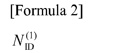
ranges from 0 to 167, corresponding to the physical-layer cell identity group. - Further,

ranges from 0 to 2, corresponding to the physical-layer cell identity in a certain physical-layer cell identity group. - Herein, three different physical-layer cell identities in the physical-layer cell identity group, i.e.,

is used as a PSS (Primary Synchronization Signal) code sequence number (e.g., Zadoff-chu sequence used in LTE). - Next, the method of allocating PCI will be described.
- The LTE mobile communication system is provided with a database for each base station in which PCIs and the like of the cells of the adjacent base stations in the neighborhood of the concerned base station have been registered. This database is arranged in, for example, a maintenance server.
- When PCI is allocated to the target cell of the target base station, a PCI, that has not been allocated as the PCI of any of the cells of adjacent base stations in the neighborhood of the target base station, is allocated to the target cell.
- Next description will be made on a cell search that is carried out by the mobile station.
- The base station is transmitting, within its own cell, notification signals included with the PCI that has been allocated to the cell, to mobile stations residing in the cell.
- The mobile station, based on PSS included in the PCI received from the cell, determines the timing of transmission at which the pilot signal is transmitted from the cell.
- Then, the mobile station, in accordance with the determined timing of transmission, receives the pilot signal and measures the reception power of the received pilot signal.
- Subsequently, the mobile station searches the cell that has the greatest reception power from among the cells whose reception power has been measured.
- Thereafter, the mobile station acquires setup information for connection to the cell, from among the notification signal that is transmitted from the cell thus searched.
- Non-Patent Document 1: 3GPP TS36.211 V9. 1.0, Section 6.11 (2010-03)
- As described above, in the LTE mobile communication system, when PCI is allocated to the target cell of the target base station, a PCI, that has not been allocated as the PCI of any of the cells of adjacent base stations in the neighborhood of the target base station, is allocated to the target cell.
- However, as stated above, PCI has a structure that uses three different physical-layer cell identities in the physical-layer cell identity group as the PSS code sequence number.
- As a result, the target cell may be allocated with the same PSS code sequence number despite the fact that a different PCI from those for the cells of the adjacent base stations is allocated.
- In such a case, the orthogonality between PSSs is lowered between the cells that are allocated with the same PSS code sequence number, so that if the timings of transmissions of the two PSSs overlap, strong interference occurs between PSSs.
- As a result, the mobile station receives strong interference from the PSS of the adjacent cell, posing a problem that the cell search performance will degrade.
- It is therefore an object of the present invention to provide a cell identifier allocation method, base station, maintenance server, and mobile communication system that can solve the above problem.
- A first cell identifier allocation method of the present invention is a cell identifier allocation method for allocating a cell identifier to a target cell of a target base station among a plurality of base stations, comprising:
- a measurement step of measuring the reception power or propagation loss of the signal received inside the target cell from each of the cells of adjacent base stations in the neighborhood of the target base station;
- an identification step of identifying the first cell that has the greatest reception power or the lowest propagation loss, from among the cells of the adjacent base stations; and,
- an allocation step of allocating a cell identifier in which the code sequence number of the synchronization signal is different from that of the first cell and that has not been allocated to any of the cells of the adjacent base stations, to the target cell.
- A second cell identifier allocation method of the present invention is a cell identifier allocation method for allocating a cell identifier to a target cell of a target base station among a plurality of base stations, comprising:
- an identification step of identifying the first cell that produces the greatest interference against the target cell, from among the cells of the adjacent base stations in the neighborhood of the target base station; and,
- an allocation step of allocating a cell identifier in which the code sequence number of the synchronization signal is different from that of the first cell and that has not been allocated to any of the cells of the adjacent base stations, to the target cell.
- A base station of the present invention is a base station that allocates a cell identifier to a target cell thereof, comprising: a
a measuring unit that measures the reception power or propagation loss of the signal received inside the target cell from among the cells of the adjacent base stations in the neighborhood of its own station; and,
an allocator that identifies the first cell that has the greatest reception power or the lowest propagation loss, from the cells of the adjacent base stations, and allocates a cell identifier in which the code sequence number of the synchronization signal is different from that of the first cell and that has not been allocated to any of the cells of the adjacent base stations, to the target cell. - A maintenance server of the present invention is a maintenance server that allocates a cell identifier to a target cell of a target base station among a plurality of base stations, comprising:
- an allocator that identifies, from among the cells of the adjacent base stations in the neighborhood of the target base station, the first cell whose reception power of the signal received inside the target cell is the greatest or whose propagation loss of the signal received inside the target cell is the lowest, and allocates a cell identifier in which the code sequence number of the synchronization signal is different from that of the first cell and that has not been allocated to any of the cells of the adjacent base stations, to the target cell.
- A mobile communication system of the present invention is a mobile communication system including a plurality of base stations and allocates a cell identifier to a target cell of a target base station among the plural base stations, comprising:
- a measuring unit that measures the reception power or propagation loss of the signal received inside the target cell from each of the cells of the adjacent base stations in the neighborhood of the target base station; and,
- an allocator that identifies the first cell that has the greatest reception power or the lowest propagation loss, from among the cells of the adjacent base stations, and allocates a cell identifier in which the code sequence number of the synchronization signal is different from that of the first cell and that has not been allocated to any of the cells of the adjacent base stations, to the target cell.
- According to the present invention, the first cell that has the greatest reception power or the lowest propagation loss is identified from among the cells of adjacent base stations in the neighborhood of the target base station, and a PCI, in which the code sequence number of the synchronization signal is different from that of the first cell and that has not been allocated to any of the cells of the adjacent base stations, is allocated to the target cell.
- Accordingly, the target cell shows high orthogonality between the synchronization signals of itself and that of the adjacent cell that is estimated to produce the strongest interference, and hence it receives less interfered from adjacent cell, so that it is possible to obtain the effect that degradation of the mobile station's cell search characteristic can be avoided.
-
- [
FIG. 1 ] A block diagram showing the configuration of a mobile communication system for the first to third exemplary embodiments of the present invention. - [
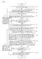
FIG. 2 ] A flow chart for explaining the operation of the maintenance terminal in the first to third exemplary embodiments of the present invention. - [
FIG. 3 ] A flow chart for explaining the operation of the maintenance server of the first exemplary embodiment of the present invention. - [
FIG. 4 ] A flow chart for explaining the operation of the base station in the first to third exemplary embodiments of the present invention. - [
FIG. 5 ] A flow chart for explaining the operation of the maintenance server of the second exemplary embodiment of the present invention. - [
FIG. 6 ] A diagram for explaining a specific example of the operation of the mobile communication system of the second exemplary embodiment of the present invention. - [
FIG. 7 ] A flow chart for explaining the operation of the maintenance server of the third exemplary embodiment of the present invention. - [
FIG. 8 ] A diagram for explaining a specific example of the operation of the mobile communication system of the third exemplary embodiment of the present invention. - [
FIG. 9 ] A block diagram showing the configuration of a mobile communication system of the fourth exemplary embodiment of the present invention. - The mode for carrying out the present invention will be described hereinbelow with reference to the drawings.
- Here, description below will be given by taking an example in which the mobile communication system of the present invention is applied to the LTE mobile communication system.
- As shown in
FIG. 1 , the mobile communication system of the present exemplary embodiment includes n (n is an integer equal to or greater than 2) base stations (eNB) (#1∼#n) 10-1∼10-n (which will be calledhereinbelow base station 10 if not otherwise specified),maintenance terminal 20 andmaintenance server 30. InFIG. 1 , only the components characterizing the present invention are shown whereas the other components are omitted. - Base stations 10-1∼10-n form cells and exchange signals with mobile stations (not shown) residing in the cells.
- When PCI is allocated to the target cell of
target base station 10,maintenance terminal 20 is moved to the target cell by the maintainer, and measures the reception power or propagation loss of the signals (e.g., pilot signals, notification signals, etc.) received inside the target cell from each cell ofadjacent base stations 10 in the neighborhood oftarget base station 10. - When PCI is allocated to the target cell of
target base station 10,maintenance server 30, based on the result ofmaintenance terminal 20's measurement of the reception power or propagation loss ofadjacent base stations 10, allocates PCI to the target cell. In this case,target base station 10 sets the target cell with the PCI that is allocated bymaintenance server 30 and transmits the PCI to mobile stations residing inside the target cell. - Here,
maintenance server 30 may be connected to base stations 10-1∼10-n andmaintenance terminal 20 in either a wired or a wireless manner, the mode of connection being not limited. - Now, the internal configurations of base stations 10-1∼10-n,
maintenance terminal 20 andmaintenance server 30 will be described. - Base station 10-1 includes
antenna 11,transmitter 12, andcontroller 13. -
Antenna 11 is provided for each cell formed by base station 10-1. Here, inFIG. 1 a plurality ofantennas 11 are shown, but the number ofantennas 11 may be one. In this case, base station 10-1 forms a single cell (omni-cell). -
Transmitter 12 transmits signals (e.g., pilot signals, notification signals, etc.) to mobile stations residing inside each cell of base station 10-1 via theantenna 11 corresponding to the cell. -
Controller 13 performs control for transmitting signals fromtransmitter 12. For example,controller 13 sets the PCI allocated to each cell of base station 10-1 bymaintenance server 30 to the cell and perform s control so as to transmit a notification signal included with the PCI to the cell. - The configurations of other base stations 10-2∼10-n are the same as that of base station 10-1.
-
Maintenance terminal 20 includes base station DB (Data Base) 21,antenna 22,mobile station receiver 23, and measuringunit 24. -
Base station DB 21 is a data base in which, for each of base stations 10-1∼10-n, the base station ID, cell number (different from PCI) and PCI of each cell ofadjacent base stations 10 in the neighborhood of thebase station 10 are registered. - Herein,
maintenance terminal 20 is moved to the target cell by the maintainer when PCI is allocated to the target cell oftarget base station 10, as state above. - In this case,
maintenance terminal 20 behaves similarly to the mobile stations residing inside the target cell and receives signals (e.g., pilot signals, notification signals, etc.) transmitted from each cell oftarget base station 10 andadjacent base stations 10 in the neighborhood oftarget base station 10, atmobile station receiver 23. - Measuring
unit 24, among the signals received atmobile station receiver 23, measures the reception power or propagation loss of the signals received fromadjacent base stations 10 in the neighborhood oftarget base station 10. Here, measuringunit 24, in measuring propagation loss, extracts the transmission power included in the notification signal first, then measures the reception power of the received signal, and determines the difference between the transmission power and the reception power as the propagation loss. -
Maintenance server 30 includesbase station DB 31 andallocator 32. -
Base station DB 31 is a data base similar tobase station DB 21. - When allocating PCI to the target cell of
target base station 10,allocator 32 identifies the cell that has the greatest reception power or the lowest propagation loss (the first cell, estimated as the cell producing the strongest interference) from among the cells ofadjacent base stations 10 in the neighborhood oftarget base station 10, based on themaintenance terminal 20's result of measurement of reception power or propagation loss. - Then,
allocator 32 allocates a PCI in which the PSS code sequence number is different from that of the cell identified above and has not been allocated to any of the cells ofadjacent base stations 10, to the target cell. - Next, the operation in the mobile communication system of the present exemplary embodiment when PCI is allocated to the target cell of
target base station 10 will be described. It is assumed hereinbelow thatmaintenance terminal 20 measures reception power. - First, the operation of
maintenance terminal 20 will be described with reference toFIG. 2 . - As shown in
FIG. 2 , when PCI is allocated to the target cell oftarget base station 10,maintenance terminal 20 is moved to the target cell by the maintainer, and the base station ID oftarget base station 10 and the cell number of the target cell are set in measuringunit 24 by the maintainer (Step A11). - Then, measuring
unit 24 refers tobase station DB 21 to confirm each cell ofadjacent base stations 10 in the neighborhood oftarget base station 10 and measures the reception power of the signals received from the cells ofadjacent base stations 10, among the signals received by mobile station receiver 23 (Step A12). - Thereafter, measuring
unit 24 outputs the base station ID oftarget base station 10, the cell number of the target cell, and the cell number and result of measurement of the reception power of each cell ofadjacent base stations 10 as the measurement information of reception power, to maintenance server 30 (Step A13). - Next, the operation of
maintenance server 30 will be described with reference toFIG. 3 . - As shown in
FIG. 3 , when PCI is allocated to the target cell oftarget base station 10, the base station ID oftarget base station 10 and the cell number of the target cell are set inallocator 32 ofmaintenance server 30 by the maintainer (Step A21). - When, in this state, the measurement information of reception power is input from maintenance terminal 20 (Step A22),
allocator 32 refers tobase station DB 31 to confirm the cells ofadjacent base stations 10 in the neighborhood oftarget base station 10. Next,allocator 32 identifies the cell that has the greatest reception power (the first cell, estimated as the cell producing the strongest interference) from among the cells ofadjacent base stations 10, based on the measurement information of reception power (Step A23). - Next,
allocator 32 refers tobase station DB 31 to confirm the PSS code sequence number allocated to the cell that has been identified at Step A23, and also to confirm the PCI allocated to each cell ofadjacent base stations 10. Next,allocator 32 allocates a PCI in which the PSS code sequence number is different from that of the cell identified at Step A23 and has not been allocated to any of the cells ofadjacent base stations 10, to the target cell (Step A24). - Thereafter,
allocator 32 outputs the PCI allocated to the target cell at Step A24 and the cell number of the target cell, to target base station 10 (Step A25). - Here, registration of the PCI allocated to the target cell at Step A24 into
base station DB 31 andbase station DB 21 may be performed at any timing after Step A24. - Next, the operation of
base station 10 will be described with reference toFIG. 4 . - As shown in
FIG. 4 , when receiving the PCI allocated to its own station from maintenance server 30 (Step A31),controller 13 sets the PCI to the target cell (Step A32). - Then,
transmitter 12 transmits a notification signal included with the PCI to mobile stations residing inside the target cell of its own station viaantenna 11 corresponding to the target cell (Step A33). - As described, in this exemplary embodiment, the cell that has the greatest reception power or the lowest propagation loss (estimated as the cell producing the strongest interference) is identified from among the cells of
adjacent base stations 10 in the neighborhood oftarget base station 10, and a PCI, in which the PSS code sequence number is different from that of the identified cell and has not been allocated to any of the cells ofadjacent base stations 10, is allocated to the target cell. - Accordingly, the target cell shows high orthogonality between the PSSs of itself and the adjacent cell that is estimated to produce the strongest interference and hence it receives less interfered from adjacent cell, so that it is possible to obtain the effect that degradation of the mobile station's cell search characteristic can be avoided.
- In this exemplary embodiment, the PCI allocating operation in the first exemplary embodiment is specified to the operation in case that base stations 10-1∼10-n have a three-cell structure consisting of three cells. In this exemplary embodiment, the overall configuration of the mobile communication system, the operations of base stations 10-1∼10-n and the operation of
maintenance terminal 20 are the same as those of the first exemplary embodiment. - Accordingly, the following description will focus on the operation of
maintenance server 30. Also, it is assumed thatmaintenance terminal 20 measures reception power. - As shown in
FIG. 5 , when PCI is allocated to the target cell oftarget base station 10, the base station ID oftarget base station 10 and the cell number of the target cell are set inallocator 32 ofmaintenance server 30 by the maintainer (Step B1). - When, in this state, the measurement information of reception power is input from maintenance terminal 20 (Step B2),
allocator 32 refers tobase station DB 31 to confirm the cells ofadjacent base stations 10 in the neighborhood oftarget base station 10. Next,allocator 32 identifies the cell that has the greatest reception power (the first cell, estimated as the cell producing the strongest interference) from among the cells ofadjacent base stations 10, based on the measurement information of reception power, and also identifies theadjacent base station 10 that forms the identified cell (estimated as the nearest adjacent base station) (Step B3). - Then,
allocator 32 identifies the cell that has the lowest reception power (the second cell, estimated as the cell having a directivity that produces the weakest interference) from among the cells formed by theadjacent base station 10 identified at Step B3, based on the measurement information of reception power (Step B4). - Next,
allocator 32 refers tobase station DB 31 to confirm the PSS code sequence number allocated to the cell that has been identified at Step B4 and also to confirm the PCI allocated to each cell ofadjacent base stations 10. Next,allocator 32 allocates a PCI in which the PSS code sequence number is the same as that of the cell identified at Step B4 and that has not been allocated to any of the cells ofadjacent base stations 10, to the target cell (Step B5). - Thereafter,
allocator 32 outputs the PCI allocated to the target cell at Step B5 and the cell number of the target cell, to target base station 10 (Step B6). - Subsequently, a specific example of the operation of the mobile communication system of the present exemplary embodiment will be described with reference to
FIG. 6 . Here, it is assumed inFIG. 6 that base stations (#2∼#5) 10-2-10-5 are located adjacent to base station (#1) 10-1. The text strings in the regular hexagon representing a cell denote "base station ID (written as eNB#)", "cell number (written as Cell#)" and "PCI" (the same notation is used inFIG. 8 below). - It is assumed hereinbelow that PCI is allocated to
cell # 1 of base station(#1) 10-1. - First, measuring
unit 24 ofmaintenance terminal 20 measures the reception power of the signal received from each of the cells of base stations (#2∼#5) 10-2∼10-5, insidecell # 1 of base station(#1) 10-1. Herein, it is assumed that the following measurement result is obtained. -
Cell # 4 of base station (#2) 10-2: -110 dBm
Cell # 5 of base station (#2) 10-2: -79 dBm
Cell # 6 of base station (#2) 10-2: -80 dBm
Cell # 7 of base station (#3) 10-3: -80 dBm
Cell # 8 of base station (#3) 10-3: -90 dBm
Cell # 9 of base station (#3) 10-3: -100 dBm
Cell # 10 of base station (#4) 10-4: -90 dBm
Cell # 11 of base station (#4) 10-4: -100 dBm
Cell # 12 of base station (#4) 10-4: -100 dBm
Cell # 13 of base station (#5) 10-5: -110 dBm
Cell # 14 of base station (#5) 10-5: -120 dBm
Cell # 15 of base station (#5) 10-5: -120 dBm - Next,
allocator 32 ofmaintenance server 30 identifies base station (#2) 10-2 that formscell # 5 that has the greatest reception power (-79dBm), from among base stations (#2∼#5) 10-2∼10-5. - Then, allocator 32 of
maintenance server 30 identifiescell # 4 of the lowest reception power (-110dBm, PCI#3(mod3 (code sequence number) is 0), from among the cells of base station (#2) 10-2. - Thereafter,
allocator 32 ofmaintenance server 30 allocates PCI#0, which has mod3 equal to 0 and which has not been allocated to any of the cells of base stations (#2∼#5) 10-2∼10-5, tocell # 1 of base station (#1) 10-1. - As described, in the exemplary embodiment, when PCI is allocated to the target cell of
target base station 10, adjacent base station 10 (estimated as the nearest adjacent base station 10) that forms the cell that has the greatest reception power or the lowest propagation loss (estimated as the cell producing the strongest interference) is identified from amongadjacent base stations 10 in the neighborhood oftarget base station 10, the cell that has the lowest reception power or the greatest propagation loss (estimated as the cell having a directivity that produces the weakest interference) is identified from among the cells formed by the identifiedadjacent base station 10, and a PCI, in which the PSS code sequence number is the same as that of the identified cell and that has not been allocated to any of the cells ofadjacent base stations 10, is allocated to the target cell. - Accordingly, the target cell shows high orthogonality the PSSs of itself and the adjacent cell that is estimated to produce the strongest interference and hence it receives less interfered from adjacent cell, so that it is possible to obtain the effect in which degradation of the mobile station's cell search characteristic can be avoided.
- In the second exemplary embodiment, there is a possibility that the same PSS code sequence number is allocated to the cells formed by the
identical base station 10. In this case, the PSSs of the cells formed by theidentical base station 10 will greatly interfere with each other. - To deal with this, in the present exemplary embodiment, when PCI is allocated to plural cells formed by
identical base station 10, the cell whose reception power is greater or whose propagation loss is smaller is given priority to be allocated with PCI so that no overlap of the PSS code sequence numbers will occur between the cells. - In this exemplary embodiment, the PCI allocating operation in the first exemplary embodiment is specified to the operation in case that base stations 10-1∼10-n have a three-cell structure. In this exemplary embodiment, the overall configuration of the mobile communication system is the same as that of the first exemplary embodiment.
- Further, the operation of
maintenance terminal 20 is the same as that of the first exemplary embodiment. However, in the case of the present exemplary embodiment,maintenance terminal 20 is successively moved to the three target cells formed bytarget base station 10, and sequentially outputs the measurement information of the reception power or propagation loss of each target cell tomaintenance server 30. - Also, base stations 10-1∼10-n operate in the same manner as in the first exemplary embodiment. However, in the present exemplary embodiment, when base stations 10-1∼10-n play a role of
target base station 10, the base station receives input of the PCIs of the three target cells formed by its own station frommaintenance server 30 and sets up the PCIs to the target cells and transmits each PCI to mobile stations residing inside the associated target cell. - Accordingly, the following description will focus on the operation of
maintenance server 30. Also, it is assumed thatmaintenance terminal 20 measures reception power. - As shown in
FIG. 7 , when it is assumed that the three cells formed bytarget base station 10 are the target cells to which PCI is allocated, the base station ID oftarget base station 10 is set inallocator 32 ofmaintenance server 30 by the maintainer (Step C1). - When, in this state, the measurement information of reception power is input from maintenance terminal 20 (Step C2),
allocator 32 refers tobase station DB 31 to confirm the target cells oftarget base station 10, also to confirm the cells ofadjacent base stations 10 in the neighborhood oftarget base station 10, and selects the target cells whose measurement information has been input, from among the target cells of target base station 10 (Step C3). - Next,
allocator 32, for the target cells selected at Step C3, identifies the cell that has the greatest reception power (the first cell, estimated as the cell producing the strongest interference) based on the measurement information of reception power, from among the cells of adjacent base stations 10 (Step C4). - Then,
allocator 32 executes Step C4 for all the target cells oftarget base station 10 so as to determine whether the cell that has the greatest reception power has been identified (Step C5). - At Step C5, if there is a target cell that has not undergone Step C4, the control waits for a new input of measurement information of an untreated target cell at Step C2 (Step C6), whereas if all the target cells have undergone Step C4, the control goes to Step C7.
- At Step C7,
allocator 32 gives priority to the target cells oftarget base station 10, in descending order of the reception power of the cell identified at Step C4. - Next,
allocator 32 selects the target cell that has the highest priority from among the target cells of target base station 10 (Step C8), and identifies theadjacent base station 10 that forms the cell identified at Step C4 (estimated as the nearest adjacent base station 10), for the selected target cell (Step C9). - Next,
allocator 32 identifies the cell that has the lowest reception power (the second cell, estimated as the cell having a directivity that produces the weakest interference) based on the measurement information of reception power, from among the cells in which the PSS code sequence number is different from the other target cells, and which are formed by theadjacent base station 10 identified at Step C9 (Step C10). Here, at Step C10 when the cell is the target cell that has the highest priority, no PCI will have been allocated at this time, so that the cell that has the lowest reception power is identified from among the cells formed byadjacent base station 10 without taking PSS into account. - Next,
allocator 32 refers tobase station DB 31 to confirm the PSS code sequence number allocated to the cell identified at Step C10 and also to confirm PCI allocated to each cell ofadjacent base stations 10. Then,allocator 32 allocates a PCI in which the PSS code sequence number is the same as that of the cell identified at Step C10 and that has not been allocated to any of the cells ofadjacent base stations 10, to the target cell (Step C11). - Next,
allocator 32 executes Step C11 for all the target cells oftarget base station 10 so as to determine whether PCI has been allocated (Step C12). - At Step C12, if there is a target cell that has not undergone Step C11, the target cell that has been untreated and that has the next high priority is selected (Step C6), and the control returns to Step C9, whereas if all the target cells have undergone Step C11, the control goes to Step C14.
- Thereafter,
allocator 32 outputs the PCI allocated to each target cell oftarget base station 10 at Step C11 and the cell number of each target cell to targetbase station 10, at Step C14. - Subsequently, a specific example of the operation of the mobile communication system of the present exemplary embodiment will be described with reference to
FIG. 8 . - Hereinbelow, PCI will be allocated to each of
cells # 1∼#3 of base station (#1) 10-1. - First, measuring
unit 24 ofmaintenance terminal 20 measures the reception power of the signal received from each of the cells of base stations (#2∼#5) 10-2∼10-5, insiderespective cells # 1, #2 and #3 of base station (#1) 10-1. - Next,
allocator 32 ofmaintenance server 30 identifies the cell that has the greatest reception power for each ofcells # 1, #2 and #3. Herein, it is assumed that identification was done as follows: - Cell #1: cell #5(PCI#4) of base station (#2) 10-2: -79 dBm
Cell #2: Cell #10(PCI#9) of base station (#4) 10-4: -90 dBm
Cell #3: Cell #13(PCI#12) of base station (#5) 10-5: -85 dBm - Next,
allocator 32 ofmaintenance server 30 gives priority tocells # 1, #2 and #3, in descending order of the reception power of the cell identified at Step c2. It is assumed herein that priority was given in the following order. -
Cell # 1, >Cell # 3 >Cell # 2 - Thereafter,
allocator 32 ofmaintenance server 30 allocates PCI to each ofcells # 1, #2 and #3 in the order of priority. - First, for
cell # 1,allocator 32 identifies the cell that has the lowest reception power, from among the cells of base station (#2) 10-2 that formscell # 5 identified at Step c2. Herein, it is assumed that the identification is done, as follows. -
Cell # 4 of base station (#2) 10-2, -110 dBm, PCI#3(mod is 3). - Accordingly,
allocator 32 allocates PCI#0, which has mod3 equal to 0 and which has not been allocated to any of the cells of base stations (#2∼#5) 10-2∼10-5, tocell # 1 of base station (#1) 10-1. - Next, for
cell # 3,allocator 32 identifies the cell that has the lowest reception power, from among the cells which have been allocated with other than 0 for mod3, and which are formed by base station (#5) 10-5 that formscell # 13 identified at Step c2. Herein, it is assumed that the identification is done, as follows. -
Cell # 14 of base station (#5) 10-5, -120 dBm, PCI#13(mod is 1). - Accordingly,
allocator 32 allocatesPCI# 15, which has mod3 equal to 1 and which has not been allocated to any of the cells of base stations (#2∼#5) 10-2∼10-5, tocell # 3 of base station (#1) 10-1. - Next, for
cell # 2,allocator 32 identifies the cell that has the lowest reception power, from among the cells which have been allocated with other than 0 and 1 (i.e., 2) for mod3, and which are formed by base station (#4) 10-4 that formscell # 10 identified at Step c2. Herein, it is assumed that the identification is done, as follows. -
Cell # 11 of base station (#4) 10-4, -124 dBm, PCI#10(mod is 2). - Accordingly,
allocator 32 allocatesPCI# 16, which has mod3 equal to 2 and which has not been allocated to any of the cells of base stations (#2∼#5) 10-2∼10-5, tocell # 2 of base station (#1) 10-1. - As described above, in the present exemplary embodiment, when PCI is allocated to a plurality of target cells formed by
target base station 10, PCI is allocated by giving priority to the cell that has a greater reception power or lower propagation loss so as to avoid overlapping of the PSS code sequence number between cells. - As a result, it is possible to obtain such an effect as to avoid interference between PSSs from increasing due to overlap of the PSS code sequence number, between the cells formed by the
same base station 10. - The other effects are the same as those in the first and second exemplary embodiments.
- As shown in
FIG. 9 , the mobile communication system of this exemplary embodiment is different from the first to third exemplary embodiments in that the functions ofmaintenance terminal 20 andmaintenance server 30 are provided in base stations 10-1∼10-n and in thatmaintenance terminal 20 andmaintenance server 30 are omitted. - That is, base station 10-1 additionally includes
antenna 15,mobile station receiver 16 and measuringunit 17 corresponding toantenna 22,mobile station receiver 23 and measuringunit 24 provided inmaintenance terminal 20. Base station 10-1 further includesbase station DB 14 corresponding tobase station DB 21 provided inmaintenance terminal 20 andbase station DB 31 provided inmaintenance server 30. Further added toinside controller 13 of base station 10-1 is allocator 18 corresponding to allocator 32 provided inmaintenance server 30. - The configuration of other base stations 10-2∼10-n are the same as that of base station 10-1.
- The present exemplary embodiment is different only in that the functions of
maintenance terminal 20 andmaintenance server 30 are provided in base stations 10-1∼10-n whereas the basic operation is unchanged, so that description of the operation is omitted. - As described above, in the present embodiment, base stations 10-1∼10-n measure the reception power or propagation loss from each of the cells of
adjacent base stations 10 in the neighborhood of its own station and allocate PCI to each of its own station. As a result, it is possible to obtain such an effect as to make base stations 10-1∼10-n to operate as SON (Self Organizing Network). - The other effects are the same as those of the first to third exemplary embodiments.
- Although the present invention has been explained with reference to the exemplary embodiments, the present invention should not be limited to the above exemplary embodiments. Various modifications that can be understood by those skilled in the art may be made to the structures and details of the present invention within the scope of the present invention.
- For example, the above embodiments were described by giving examples using PSS as the synchronization signal. However, other synchronization signals than PSS may be used.
- Specifically, for the adjacent cell that is estimated to produce the greatest interference with the target cell, the code sequence number (e.g., a Gold sequence) of SSS (Secondary Synchronization Signal) may be made different so as to enhance the orthogonality between SSSs of the target cell and the adjacent cell, whereby it is possible to adequately reduce the interference from the adjacent cell.
- Also, the second and third exemplary embodiments were described by giving examples in which base stations 10-1∼10-n have a three-cell structure, but the number of cells formed by base stations 10-1∼10-n is not limited to this.
- This application claims priority based on Japanese Patent Application No.
2011-257614, filed on November 25, 2011
Claims (9)
- A cell identifier allocation method for allocating a cell identifier to a target cell of a target base station among a plurality of base stations, comprising:a measurement step of measuring the reception power or propagation loss of the signal received inside the target cell from each of the cells of adjacent base stations in the neighborhood of the target cell;an identification step of identifying the first cell that has the greatest reception power or the lowest propagation loss, from among the cells of the adjacent base stations; and,an allocation step of allocating a cell identifier in which the code sequence number of the synchronization signal is different from that of the first cell and that has not been allocated to any of the cells of the adjacent base stations, to the target cell.
- The cell identifier allocation method according to Claim 1, wherein each of the plural base stations forms a plurality of cells, and
the allocation step includes:identifying the second cell that has the lowest reception power or the greatest propagation loss, from among the plural cells of the adjacent base station that forms the first cell; and,allocating a cell identifier in which code sequence number of the synchronization signal is the same as that of the second cell and that has not been allocated to any of the cells of the adjacent base stations, to the target cell. - The cell identifier allocation method according to Claim 1, wherein each of the plural base stations forms a plurality of cells, and
the identification step includes:when plural cells of the target base station are handled as the target cells,identifying the first cell for each of the target cells;the allocation step includes:when plural cells of the target base station are handled as the target cells,giving priority to the each of target cells, in descending order of the reception power of the first cell, or in ascending order of the propagation loss of the first cell;for each of the target cells, in the order of the highest priority, identifying the second cell that has the lowest reception power or the greatest propagation loss, from among the cells in which the code sequence number of the synchronization signal is different from that of the other target cells, and which are formed by the adjacent base station that forms the first cell; and,for each of the target cells, in the order of the highest priority, allocating a cell identifier in which code sequence number of the synchronization signal is the same as that of the second cell and that has not been allocated to any of the cells of the adjacent base stations, to each of the target cells. - The cell identifier allocation method according to any of Claims 1 to 3, wherein, in the measurement step,
a separate device from the target base station receives signals inside the target cell from each of the cells of the adjacent base stations and measures the reception power or propagation loss of the received signal. - The cell identifier allocation method according to any one of Claims 1 to 3, wherein, in the measurement step,
the target base station receives signals inside the target cell from each of the cells of the adjacent base stations and measures the reception power or propagation loss of the received signal. - A cell identifier allocation method for allocating a cell identifier to a target cell of a target base station among a plurality of base stations, comprising:an identification step of identifying the first cell that produces the greatest interference against the target cell, from among the cells of the adjacent base stations in the neighborhood of the target base station; and,an allocation step of allocating a cell identifier in which the code sequence number of the synchronization signal is different from that of the first cell and that has not been allocated to any of the cells of the adjacent base stations, to the target cell.
- A base station that allocates a cell identifier to a target cell thereof, comprising: a a measuring unit that measures the reception power or propagation loss of the signal received inside the target cell from among the cells of the adjacent base stations in the neighborhood of its own station; and,
an allocator that identifies the first cell that has the greatest reception power or the lowest propagation loss, from among the cells of the adjacent base stations, and allocates a cell identifier in which the code sequence number of the synchronization signal is different from that of the first cell and that has not been allocated to any of the cells of the adjacent base stations, to the target cell. - A maintenance server that allocates a cell identifier to a target cell of a target base station among a plurality of base stations, comprising:an allocator that identifies, from among the cells of the adjacent base stations in the neighborhood of the target base station, the first cell whose reception power of the signal received inside the target cell is the greatest or whose propagation loss of the signal received inside the target cell is the lowest, and allocates a cell identifier in which the code sequence number of the synchronization signal is different from that of the first cell and that has not been allocated to any of the cells of the adjacent base stations, to the target cell.
- A mobile communication system including a plurality of base stations and that allocates a cell identifier to a target cell of a target base station among the plural base stations, comprising:a measuring unit that measures the reception power or propagation loss of the signal received inside the target cell from each of the cells of the adjacent base stations in the neighborhood of the target base station; and,an allocator that identifies the first cell that has the greatest reception power or the lowest propagation loss, from among the cells of the adjacent base stations, and allocates a cell identifier in which the code sequence number of the synchronization signal is different from that of the first cell and that has not been allocated to any of the cells of the adjacent base stations, to the target cell.
Applications Claiming Priority (2)
| Application Number | Priority Date | Filing Date | Title |
|---|---|---|---|
| JP2011257614 | 2011-11-25 | ||
| PCT/JP2012/072911 WO2013077059A1 (en) | 2011-11-25 | 2012-09-07 | Cell identifier allocation method, base station, maintenance server, and mobile communication system |
Publications (3)
| Publication Number | Publication Date |
|---|---|
| EP2785087A1 true EP2785087A1 (en) | 2014-10-01 |
| EP2785087A4 EP2785087A4 (en) | 2015-09-09 |
| EP2785087B1 EP2785087B1 (en) | 2019-09-04 |
Family
ID=48469518
Family Applications (1)
| Application Number | Title | Priority Date | Filing Date |
|---|---|---|---|
| EP12851863.6A Active EP2785087B1 (en) | 2011-11-25 | 2012-09-07 | Cell identifier allocation method, base station, maintenance server, and mobile communication system |
Country Status (6)
| Country | Link |
|---|---|
| US (1) | US9392612B2 (en) |
| EP (1) | EP2785087B1 (en) |
| JP (1) | JP5783264B2 (en) |
| KR (1) | KR101607793B1 (en) |
| CN (1) | CN103947236A (en) |
| WO (1) | WO2013077059A1 (en) |
Cited By (1)
| Publication number | Priority date | Publication date | Assignee | Title |
|---|---|---|---|---|
| EP3101933A4 (en) * | 2014-01-27 | 2016-12-07 | Shanghai datang mobile communications equipment co ltd | METHOD AND APPARATUS FOR ASSIGNING IDENTIFIERS OF PHYSICAL CELLS |
Families Citing this family (11)
| Publication number | Priority date | Publication date | Assignee | Title |
|---|---|---|---|---|
| US9660748B2 (en) | 2012-12-04 | 2017-05-23 | Nokia Solutions And Networks Oy | Algorithm for physical cell identifier allocation |
| JP2015002494A (en) * | 2013-06-18 | 2015-01-05 | 株式会社日立製作所 | Communication device, wireless communication system, wireless communication method, and terminal |
| EP3105960B1 (en) * | 2014-02-14 | 2019-06-05 | Telefonaktiebolaget LM Ericsson (publ) | Wireless device and method for managing measurement of reference signals |
| JOP20150179B1 (en) | 2014-08-01 | 2021-08-17 | Janssen Pharmaceutica Nv | Compounds of 6, 7-dihydropyrazolo[1,5alpha]pyrazine-4(5H)-en and their use as negative Wisteria regulators of Melgor II receptors |
| JOP20150177B1 (en) | 2014-08-01 | 2021-08-17 | Janssen Pharmaceutica Nv | Compounds of 6, 7-dihydropyrazolo[1,5alpha]pyrazine-4(5H)-en and their use as negative Wisteria regulators of Melgor II receptors |
| CN105636063B (en) * | 2014-10-29 | 2018-12-07 | 中国移动通信集团江苏有限公司 | The method and Nanocell of Nanocell are configured in LTE |
| KR102190122B1 (en) * | 2015-01-15 | 2020-12-11 | 주식회사 케이티 | Method and apparatus for allocating physical cell identity |
| JP2018520601A (en) * | 2015-07-10 | 2018-07-26 | エルジー エレクトロニクス インコーポレイティド | Method and apparatus for transmitting discovery reference signal in wireless connection system supporting unlicensed band |
| CN106612502B (en) * | 2015-10-22 | 2019-11-12 | 普天信息技术有限公司 | Method and system for acquiring physical cell identity PCI |
| EP3592103B1 (en) * | 2017-03-24 | 2020-10-21 | Huawei Technologies Co., Ltd. | Method for transmitting system information |
| KR102874403B1 (en) * | 2020-10-30 | 2025-10-22 | 에스케이텔레콤 주식회사 | Cell apparatus, and method thereof |
Family Cites Families (13)
| Publication number | Priority date | Publication date | Assignee | Title |
|---|---|---|---|---|
| JPH0955974A (en) | 1995-08-11 | 1997-02-25 | Matsushita Electric Ind Co Ltd | Mobile communication device |
| WO2008007775A1 (en) * | 2006-07-13 | 2008-01-17 | Nec Corporation | Cellular system, its carrier allocation method, base station, and mobile station |
| KR20090085504A (en) * | 2008-02-04 | 2009-08-07 | 한국전자통신연구원 | Interference Mitigation Method in Orthogonal Frequency Division Multiple Access-based Cellular Systems |
| US8391158B2 (en) * | 2008-07-25 | 2013-03-05 | Qualcomm Incorporated | Cell identifier assignment and selection |
| US8731573B2 (en) * | 2009-05-08 | 2014-05-20 | Telefonaktiebolaget L M Ericsson (Publ) | Allocation of primary and secondary synchronization code sequences to cells in a wireless communication system |
| CN101888622B (en) | 2009-05-14 | 2015-06-10 | 株式会社Ntt都科摩 | Method and device for distributing physical layer cell identifiers |
| CN101965057B (en) * | 2009-07-23 | 2014-07-09 | 华为技术有限公司 | Method, equipment and system for distributing physical cell ID |
| EP2326127B1 (en) | 2009-11-18 | 2017-11-15 | Mitsubishi Electric R&D Centre Europe B.V. | Method and a device for controlling signals transferred by a wireless telecommunication device |
| JP5282725B2 (en) | 2009-12-10 | 2013-09-04 | 富士通株式会社 | Radio base station and cell identifier specifying method |
| JP5523867B2 (en) * | 2010-02-23 | 2014-06-18 | 京セラ株式会社 | COMMUNICATION SYSTEM, CONTROL DEVICE, AND BASE STATION DEVICE |
| JP5516164B2 (en) * | 2010-07-09 | 2014-06-11 | 富士通株式会社 | Cell identifier determination method, radio base station, and radio communication system |
| CN102075945B (en) * | 2010-12-22 | 2013-07-03 | 北京邮电大学 | Method for distributing distributed physical cell identity in LTE wireless access network |
| WO2012107986A1 (en) * | 2011-02-10 | 2012-08-16 | パナソニック株式会社 | Wireless communication terminal, wireless communication device and wireless communication system, as well as measuring method |
-
2012
- 2012-09-07 EP EP12851863.6A patent/EP2785087B1/en active Active
- 2012-09-07 KR KR1020147017408A patent/KR101607793B1/en not_active Expired - Fee Related
- 2012-09-07 CN CN201280057815.2A patent/CN103947236A/en active Pending
- 2012-09-07 WO PCT/JP2012/072911 patent/WO2013077059A1/en not_active Ceased
- 2012-09-07 JP JP2013545822A patent/JP5783264B2/en active Active
- 2012-09-07 US US14/352,997 patent/US9392612B2/en active Active
Cited By (2)
| Publication number | Priority date | Publication date | Assignee | Title |
|---|---|---|---|---|
| EP3101933A4 (en) * | 2014-01-27 | 2016-12-07 | Shanghai datang mobile communications equipment co ltd | METHOD AND APPARATUS FOR ASSIGNING IDENTIFIERS OF PHYSICAL CELLS |
| US10075842B2 (en) | 2014-01-27 | 2018-09-11 | Shanghai Datang Mobile Communications Equipment Co., Ltd. | Physical cell identifier allocation method and apparatus |
Also Published As
| Publication number | Publication date |
|---|---|
| EP2785087A4 (en) | 2015-09-09 |
| WO2013077059A1 (en) | 2013-05-30 |
| US20140248896A1 (en) | 2014-09-04 |
| JP5783264B2 (en) | 2015-09-24 |
| KR20140095104A (en) | 2014-07-31 |
| EP2785087B1 (en) | 2019-09-04 |
| CN103947236A (en) | 2014-07-23 |
| US9392612B2 (en) | 2016-07-12 |
| JPWO2013077059A1 (en) | 2015-04-27 |
| KR101607793B1 (en) | 2016-03-30 |
Similar Documents
| Publication | Publication Date | Title |
|---|---|---|
| EP2785087B1 (en) | Cell identifier allocation method, base station, maintenance server, and mobile communication system | |
| US11153890B2 (en) | Method and system for managing UE-to-UE interference in a mobile telecommunication network | |
| CN111988098B (en) | Base station, terminal, integrated circuit and communication method | |
| US9794948B2 (en) | Communication control device, communication control method, and base station | |
| WO2017014600A1 (en) | Method and device for operating machine type device in wireless communication system | |
| KR101909968B1 (en) | Resource scheduling method and apparatus | |
| EP2547009A1 (en) | Method and device for stations to share and determine cell identity of stations during cooperative communication | |
| RU2015120802A (en) | FLEXIBLE SPECTRUM SUPPORT IN CELLULAR WIRELESS COMMUNICATION | |
| EP3445105B1 (en) | Mobile station, base station, wireless communication system, and wireless communication method | |
| CN112237039B (en) | Resource allocation for cross-link interference measurement | |
| US20170367032A1 (en) | Method and Apparatus for Reporting and Processing Proximity Service Capability Information | |
| WO2016142776A2 (en) | Method and apparatus of implementing otdoa in an indoor communication system | |
| CN111373770B (en) | Electronic devices, user equipment, methods and computer-readable storage media | |
| US20250071719A1 (en) | Positioning reference signal configuration and measurement update | |
| US10560922B2 (en) | Channel transmission method, base station, and terminal device | |
| US10334630B2 (en) | System and method for user-over-control plane messaging in a wireless network | |
| JP2025532154A (en) | Repeaters, terminal devices, and network devices | |
| US20120135770A1 (en) | Method for adjusting channels in cognitive wireless communication, and cognitive wireless communication system capable of implementing the method | |
| US9374820B2 (en) | Dynamic temporary block flow scheduling | |
| EP2996433A1 (en) | Method, apparatus and user equipment for network coverage-free neighbor discovery | |
| CN104244316A (en) | Discovery signal detecting method and equipment thereof | |
| WO2015123204A1 (en) | Method and apparatus for cell identification and reporting using pss/sss together with a discovery signal | |
| KR20250102955A (en) | Method and apparatus for configuration of resource pattern for sidelink positioning in wireless communication system | |
| JP5745166B2 (en) | Resource multiplexing method and apparatus, and handover method and apparatus | |
| KR20250102956A (en) | Method and apparatus for pssch transmission for sidelink positioning in wireless communication system |
Legal Events
| Date | Code | Title | Description |
|---|---|---|---|
| PUAI | Public reference made under article 153(3) epc to a published international application that has entered the european phase |
Free format text: ORIGINAL CODE: 0009012 |
|
| 17P | Request for examination filed |
Effective date: 20140321 |
|
| AK | Designated contracting states |
Kind code of ref document: A1 Designated state(s): AL AT BE BG CH CY CZ DE DK EE ES FI FR GB GR HR HU IE IS IT LI LT LU LV MC MK MT NL NO PL PT RO RS SE SI SK SM TR |
|
| DAX | Request for extension of the european patent (deleted) | ||
| RIC1 | Information provided on ipc code assigned before grant |
Ipc: H04W 24/08 20090101ALN20150727BHEP Ipc: H04W 72/08 20090101AFI20150727BHEP Ipc: H04W 24/02 20090101ALN20150727BHEP |
|
| RA4 | Supplementary search report drawn up and despatched (corrected) |
Effective date: 20150807 |
|
| RIC1 | Information provided on ipc code assigned before grant |
Ipc: H04W 24/02 20090101ALN20150731BHEP Ipc: H04W 24/08 20090101ALN20150731BHEP Ipc: H04W 72/08 20090101AFI20150731BHEP |
|
| STAA | Information on the status of an ep patent application or granted ep patent |
Free format text: STATUS: EXAMINATION IS IN PROGRESS |
|
| 17Q | First examination report despatched |
Effective date: 20180725 |
|
| REG | Reference to a national code |
Ref country code: DE Ref legal event code: R079 Ref document number: 602012063741 Country of ref document: DE Free format text: PREVIOUS MAIN CLASS: H04W0008260000 Ipc: H04W0072040000 |
|
| GRAP | Despatch of communication of intention to grant a patent |
Free format text: ORIGINAL CODE: EPIDOSNIGR1 |
|
| STAA | Information on the status of an ep patent application or granted ep patent |
Free format text: STATUS: GRANT OF PATENT IS INTENDED |
|
| RIC1 | Information provided on ipc code assigned before grant |
Ipc: H04W 72/04 20090101AFI20190306BHEP Ipc: H04W 24/02 20090101ALN20190306BHEP |
|
| INTG | Intention to grant announced |
Effective date: 20190401 |
|
| GRAS | Grant fee paid |
Free format text: ORIGINAL CODE: EPIDOSNIGR3 |
|
| GRAA | (expected) grant |
Free format text: ORIGINAL CODE: 0009210 |
|
| STAA | Information on the status of an ep patent application or granted ep patent |
Free format text: STATUS: THE PATENT HAS BEEN GRANTED |
|
| AK | Designated contracting states |
Kind code of ref document: B1 Designated state(s): AL AT BE BG CH CY CZ DE DK EE ES FI FR GB GR HR HU IE IS IT LI LT LU LV MC MK MT NL NO PL PT RO RS SE SI SK SM TR |
|
| REG | Reference to a national code |
Ref country code: GB Ref legal event code: FG4D |
|
| REG | Reference to a national code |
Ref country code: CH Ref legal event code: EP |
|
| REG | Reference to a national code |
Ref country code: AT Ref legal event code: REF Ref document number: 1177201 Country of ref document: AT Kind code of ref document: T Effective date: 20190915 |
|
| REG | Reference to a national code |
Ref country code: DE Ref legal event code: R096 Ref document number: 602012063741 Country of ref document: DE |
|
| REG | Reference to a national code |
Ref country code: IE Ref legal event code: FG4D |
|
| REG | Reference to a national code |
Ref country code: NL Ref legal event code: MP Effective date: 20190904 |
|
| REG | Reference to a national code |
Ref country code: LT Ref legal event code: MG4D |
|
| PG25 | Lapsed in a contracting state [announced via postgrant information from national office to epo] |
Ref country code: FI Free format text: LAPSE BECAUSE OF FAILURE TO SUBMIT A TRANSLATION OF THE DESCRIPTION OR TO PAY THE FEE WITHIN THE PRESCRIBED TIME-LIMIT Effective date: 20190904 Ref country code: HR Free format text: LAPSE BECAUSE OF FAILURE TO SUBMIT A TRANSLATION OF THE DESCRIPTION OR TO PAY THE FEE WITHIN THE PRESCRIBED TIME-LIMIT Effective date: 20190904 Ref country code: SE Free format text: LAPSE BECAUSE OF FAILURE TO SUBMIT A TRANSLATION OF THE DESCRIPTION OR TO PAY THE FEE WITHIN THE PRESCRIBED TIME-LIMIT Effective date: 20190904 Ref country code: NO Free format text: LAPSE BECAUSE OF FAILURE TO SUBMIT A TRANSLATION OF THE DESCRIPTION OR TO PAY THE FEE WITHIN THE PRESCRIBED TIME-LIMIT Effective date: 20191204 Ref country code: LT Free format text: LAPSE BECAUSE OF FAILURE TO SUBMIT A TRANSLATION OF THE DESCRIPTION OR TO PAY THE FEE WITHIN THE PRESCRIBED TIME-LIMIT Effective date: 20190904 Ref country code: BG Free format text: LAPSE BECAUSE OF FAILURE TO SUBMIT A TRANSLATION OF THE DESCRIPTION OR TO PAY THE FEE WITHIN THE PRESCRIBED TIME-LIMIT Effective date: 20191204 |
|
| PG25 | Lapsed in a contracting state [announced via postgrant information from national office to epo] |
Ref country code: LV Free format text: LAPSE BECAUSE OF FAILURE TO SUBMIT A TRANSLATION OF THE DESCRIPTION OR TO PAY THE FEE WITHIN THE PRESCRIBED TIME-LIMIT Effective date: 20190904 Ref country code: AL Free format text: LAPSE BECAUSE OF FAILURE TO SUBMIT A TRANSLATION OF THE DESCRIPTION OR TO PAY THE FEE WITHIN THE PRESCRIBED TIME-LIMIT Effective date: 20190904 Ref country code: ES Free format text: LAPSE BECAUSE OF FAILURE TO SUBMIT A TRANSLATION OF THE DESCRIPTION OR TO PAY THE FEE WITHIN THE PRESCRIBED TIME-LIMIT Effective date: 20190904 Ref country code: GR Free format text: LAPSE BECAUSE OF FAILURE TO SUBMIT A TRANSLATION OF THE DESCRIPTION OR TO PAY THE FEE WITHIN THE PRESCRIBED TIME-LIMIT Effective date: 20191205 Ref country code: RS Free format text: LAPSE BECAUSE OF FAILURE TO SUBMIT A TRANSLATION OF THE DESCRIPTION OR TO PAY THE FEE WITHIN THE PRESCRIBED TIME-LIMIT Effective date: 20190904 |
|
| REG | Reference to a national code |
Ref country code: AT Ref legal event code: MK05 Ref document number: 1177201 Country of ref document: AT Kind code of ref document: T Effective date: 20190904 |
|
| PG25 | Lapsed in a contracting state [announced via postgrant information from national office to epo] |
Ref country code: EE Free format text: LAPSE BECAUSE OF FAILURE TO SUBMIT A TRANSLATION OF THE DESCRIPTION OR TO PAY THE FEE WITHIN THE PRESCRIBED TIME-LIMIT Effective date: 20190904 Ref country code: PL Free format text: LAPSE BECAUSE OF FAILURE TO SUBMIT A TRANSLATION OF THE DESCRIPTION OR TO PAY THE FEE WITHIN THE PRESCRIBED TIME-LIMIT Effective date: 20190904 Ref country code: RO Free format text: LAPSE BECAUSE OF FAILURE TO SUBMIT A TRANSLATION OF THE DESCRIPTION OR TO PAY THE FEE WITHIN THE PRESCRIBED TIME-LIMIT Effective date: 20190904 Ref country code: NL Free format text: LAPSE BECAUSE OF FAILURE TO SUBMIT A TRANSLATION OF THE DESCRIPTION OR TO PAY THE FEE WITHIN THE PRESCRIBED TIME-LIMIT Effective date: 20190904 Ref country code: PT Free format text: LAPSE BECAUSE OF FAILURE TO SUBMIT A TRANSLATION OF THE DESCRIPTION OR TO PAY THE FEE WITHIN THE PRESCRIBED TIME-LIMIT Effective date: 20200106 Ref country code: IT Free format text: LAPSE BECAUSE OF FAILURE TO SUBMIT A TRANSLATION OF THE DESCRIPTION OR TO PAY THE FEE WITHIN THE PRESCRIBED TIME-LIMIT Effective date: 20190904 Ref country code: AT Free format text: LAPSE BECAUSE OF FAILURE TO SUBMIT A TRANSLATION OF THE DESCRIPTION OR TO PAY THE FEE WITHIN THE PRESCRIBED TIME-LIMIT Effective date: 20190904 |
|
| PG25 | Lapsed in a contracting state [announced via postgrant information from national office to epo] |
Ref country code: SK Free format text: LAPSE BECAUSE OF FAILURE TO SUBMIT A TRANSLATION OF THE DESCRIPTION OR TO PAY THE FEE WITHIN THE PRESCRIBED TIME-LIMIT Effective date: 20190904 Ref country code: CZ Free format text: LAPSE BECAUSE OF FAILURE TO SUBMIT A TRANSLATION OF THE DESCRIPTION OR TO PAY THE FEE WITHIN THE PRESCRIBED TIME-LIMIT Effective date: 20190904 Ref country code: SM Free format text: LAPSE BECAUSE OF FAILURE TO SUBMIT A TRANSLATION OF THE DESCRIPTION OR TO PAY THE FEE WITHIN THE PRESCRIBED TIME-LIMIT Effective date: 20190904 Ref country code: IS Free format text: LAPSE BECAUSE OF FAILURE TO SUBMIT A TRANSLATION OF THE DESCRIPTION OR TO PAY THE FEE WITHIN THE PRESCRIBED TIME-LIMIT Effective date: 20200224 |
|
| REG | Reference to a national code |
Ref country code: CH Ref legal event code: PL |
|
| REG | Reference to a national code |
Ref country code: DE Ref legal event code: R097 Ref document number: 602012063741 Country of ref document: DE |
|
| PLBE | No opposition filed within time limit |
Free format text: ORIGINAL CODE: 0009261 |
|
| STAA | Information on the status of an ep patent application or granted ep patent |
Free format text: STATUS: NO OPPOSITION FILED WITHIN TIME LIMIT |
|
| PG2D | Information on lapse in contracting state deleted |
Ref country code: IS |
|
| PG25 | Lapsed in a contracting state [announced via postgrant information from national office to epo] |
Ref country code: LI Free format text: LAPSE BECAUSE OF NON-PAYMENT OF DUE FEES Effective date: 20190930 Ref country code: CH Free format text: LAPSE BECAUSE OF NON-PAYMENT OF DUE FEES Effective date: 20190930 Ref country code: DK Free format text: LAPSE BECAUSE OF FAILURE TO SUBMIT A TRANSLATION OF THE DESCRIPTION OR TO PAY THE FEE WITHIN THE PRESCRIBED TIME-LIMIT Effective date: 20190904 Ref country code: LU Free format text: LAPSE BECAUSE OF NON-PAYMENT OF DUE FEES Effective date: 20190907 Ref country code: IE Free format text: LAPSE BECAUSE OF NON-PAYMENT OF DUE FEES Effective date: 20190907 Ref country code: IS Free format text: LAPSE BECAUSE OF FAILURE TO SUBMIT A TRANSLATION OF THE DESCRIPTION OR TO PAY THE FEE WITHIN THE PRESCRIBED TIME-LIMIT Effective date: 20200105 |
|
| REG | Reference to a national code |
Ref country code: BE Ref legal event code: MM Effective date: 20190930 |
|
| 26N | No opposition filed |
Effective date: 20200605 |
|
| PG25 | Lapsed in a contracting state [announced via postgrant information from national office to epo] |
Ref country code: SI Free format text: LAPSE BECAUSE OF FAILURE TO SUBMIT A TRANSLATION OF THE DESCRIPTION OR TO PAY THE FEE WITHIN THE PRESCRIBED TIME-LIMIT Effective date: 20190904 Ref country code: MC Free format text: LAPSE BECAUSE OF FAILURE TO SUBMIT A TRANSLATION OF THE DESCRIPTION OR TO PAY THE FEE WITHIN THE PRESCRIBED TIME-LIMIT Effective date: 20190904 Ref country code: BE Free format text: LAPSE BECAUSE OF NON-PAYMENT OF DUE FEES Effective date: 20190930 |
|
| PG25 | Lapsed in a contracting state [announced via postgrant information from national office to epo] |
Ref country code: FR Free format text: LAPSE BECAUSE OF NON-PAYMENT OF DUE FEES Effective date: 20191104 |
|
| PG25 | Lapsed in a contracting state [announced via postgrant information from national office to epo] |
Ref country code: CY Free format text: LAPSE BECAUSE OF FAILURE TO SUBMIT A TRANSLATION OF THE DESCRIPTION OR TO PAY THE FEE WITHIN THE PRESCRIBED TIME-LIMIT Effective date: 20190904 |
|
| PG25 | Lapsed in a contracting state [announced via postgrant information from national office to epo] |
Ref country code: MT Free format text: LAPSE BECAUSE OF FAILURE TO SUBMIT A TRANSLATION OF THE DESCRIPTION OR TO PAY THE FEE WITHIN THE PRESCRIBED TIME-LIMIT Effective date: 20190904 Ref country code: HU Free format text: LAPSE BECAUSE OF FAILURE TO SUBMIT A TRANSLATION OF THE DESCRIPTION OR TO PAY THE FEE WITHIN THE PRESCRIBED TIME-LIMIT; INVALID AB INITIO Effective date: 20120907 |
|
| PG25 | Lapsed in a contracting state [announced via postgrant information from national office to epo] |
Ref country code: TR Free format text: LAPSE BECAUSE OF FAILURE TO SUBMIT A TRANSLATION OF THE DESCRIPTION OR TO PAY THE FEE WITHIN THE PRESCRIBED TIME-LIMIT Effective date: 20190904 |
|
| PG25 | Lapsed in a contracting state [announced via postgrant information from national office to epo] |
Ref country code: MK Free format text: LAPSE BECAUSE OF FAILURE TO SUBMIT A TRANSLATION OF THE DESCRIPTION OR TO PAY THE FEE WITHIN THE PRESCRIBED TIME-LIMIT Effective date: 20190904 |
|
| PGFP | Annual fee paid to national office [announced via postgrant information from national office to epo] |
Ref country code: DE Payment date: 20240918 Year of fee payment: 13 |
|
| PGFP | Annual fee paid to national office [announced via postgrant information from national office to epo] |
Ref country code: GB Payment date: 20240919 Year of fee payment: 13 |