EP2784917A2 - Machine for generating electrical energy - Google Patents
Machine for generating electrical energy Download PDFInfo
- Publication number
- EP2784917A2 EP2784917A2 EP20140156147 EP14156147A EP2784917A2 EP 2784917 A2 EP2784917 A2 EP 2784917A2 EP 20140156147 EP20140156147 EP 20140156147 EP 14156147 A EP14156147 A EP 14156147A EP 2784917 A2 EP2784917 A2 EP 2784917A2
- Authority
- EP
- European Patent Office
- Prior art keywords
- shaft
- chute
- direct current
- machine according
- housing
- Prior art date
- Legal status (The legal status is an assumption and is not a legal conclusion. Google has not performed a legal analysis and makes no representation as to the accuracy of the status listed.)
- Withdrawn
Links
- 239000000463 material Substances 0.000 claims abstract description 39
- 238000004804 winding Methods 0.000 claims abstract description 28
- 235000013339 cereals Nutrition 0.000 claims description 7
- 239000012773 agricultural material Substances 0.000 claims description 4
- 238000004146 energy storage Methods 0.000 claims description 4
- 238000003306 harvesting Methods 0.000 claims description 4
- 244000068988 Glycine max Species 0.000 claims description 2
- 235000010469 Glycine max Nutrition 0.000 claims description 2
- 240000005979 Hordeum vulgare Species 0.000 claims description 2
- 235000007340 Hordeum vulgare Nutrition 0.000 claims description 2
- 241000209140 Triticum Species 0.000 claims description 2
- 235000021307 Triticum Nutrition 0.000 claims description 2
- 240000008042 Zea mays Species 0.000 claims description 2
- 235000005824 Zea mays ssp. parviglumis Nutrition 0.000 claims description 2
- 235000002017 Zea mays subsp mays Nutrition 0.000 claims description 2
- 235000005822 corn Nutrition 0.000 claims description 2
- 230000005484 gravity Effects 0.000 claims description 2
- 238000001914 filtration Methods 0.000 claims 2
- 239000003990 capacitor Substances 0.000 description 8
- 238000010586 diagram Methods 0.000 description 4
- 241000196324 Embryophyta Species 0.000 description 3
- 230000001419 dependent effect Effects 0.000 description 3
- 235000007319 Avena orientalis Nutrition 0.000 description 1
- 244000075850 Avena orientalis Species 0.000 description 1
- 229920000742 Cotton Polymers 0.000 description 1
- 241000219146 Gossypium Species 0.000 description 1
- 240000007594 Oryza sativa Species 0.000 description 1
- 235000007164 Oryza sativa Nutrition 0.000 description 1
- 239000000835 fiber Substances 0.000 description 1
- 239000004459 forage Substances 0.000 description 1
- 238000012986 modification Methods 0.000 description 1
- 230000004048 modification Effects 0.000 description 1
- 235000009566 rice Nutrition 0.000 description 1
- 239000010907 stover Substances 0.000 description 1
Images

Classifications
-
- F—MECHANICAL ENGINEERING; LIGHTING; HEATING; WEAPONS; BLASTING
- F04—POSITIVE - DISPLACEMENT MACHINES FOR LIQUIDS; PUMPS FOR LIQUIDS OR ELASTIC FLUIDS
- F04D—NON-POSITIVE-DISPLACEMENT PUMPS
- F04D13/00—Pumping installations or systems
- F04D13/02—Units comprising pumps and their driving means
-
- A—HUMAN NECESSITIES
- A01—AGRICULTURE; FORESTRY; ANIMAL HUSBANDRY; HUNTING; TRAPPING; FISHING
- A01D—HARVESTING; MOWING
- A01D41/00—Combines, i.e. harvesters or mowers combined with threshing devices
- A01D41/12—Details of combines
- A01D41/1208—Tanks for grain or chaff
- A01D41/1217—Unloading mechanisms
-
- A—HUMAN NECESSITIES
- A01—AGRICULTURE; FORESTRY; ANIMAL HUSBANDRY; HUNTING; TRAPPING; FISHING
- A01D—HARVESTING; MOWING
- A01D69/00—Driving mechanisms or parts thereof for harvesters or mowers
- A01D69/02—Driving mechanisms or parts thereof for harvesters or mowers electric
-
- F—MECHANICAL ENGINEERING; LIGHTING; HEATING; WEAPONS; BLASTING
- F03—MACHINES OR ENGINES FOR LIQUIDS; WIND, SPRING, OR WEIGHT MOTORS; PRODUCING MECHANICAL POWER OR A REACTIVE PROPULSIVE THRUST, NOT OTHERWISE PROVIDED FOR
- F03G—SPRING, WEIGHT, INERTIA OR LIKE MOTORS; MECHANICAL-POWER PRODUCING DEVICES OR MECHANISMS, NOT OTHERWISE PROVIDED FOR OR USING ENERGY SOURCES NOT OTHERWISE PROVIDED FOR
- F03G3/00—Other motors, e.g. gravity or inertia motors
- F03G3/04—Other motors, e.g. gravity or inertia motors driven by sand or like fluent solid material
-
- G—PHYSICS
- G01—MEASURING; TESTING
- G01F—MEASURING VOLUME, VOLUME FLOW, MASS FLOW OR LIQUID LEVEL; METERING BY VOLUME
- G01F1/00—Measuring the volume flow or mass flow of fluid or fluent solid material wherein the fluid passes through a meter in a continuous flow
- G01F1/05—Measuring the volume flow or mass flow of fluid or fluent solid material wherein the fluid passes through a meter in a continuous flow by using mechanical effects
- G01F1/10—Measuring the volume flow or mass flow of fluid or fluent solid material wherein the fluid passes through a meter in a continuous flow by using mechanical effects using rotating vanes with axial admission
-
- H—ELECTRICITY
- H02—GENERATION; CONVERSION OR DISTRIBUTION OF ELECTRIC POWER
- H02K—DYNAMO-ELECTRIC MACHINES
- H02K7/00—Arrangements for handling mechanical energy structurally associated with dynamo-electric machines, e.g. structural association with mechanical driving motors or auxiliary dynamo-electric machines
- H02K7/18—Structural association of electric generators with mechanical driving motors, e.g. with turbines
- H02K7/1807—Rotary generators
- H02K7/1823—Rotary generators structurally associated with turbines or similar engines
-
- H—ELECTRICITY
- H02—GENERATION; CONVERSION OR DISTRIBUTION OF ELECTRIC POWER
- H02K—DYNAMO-ELECTRIC MACHINES
- H02K16/00—Machines with more than one rotor or stator
-
- H—ELECTRICITY
- H02—GENERATION; CONVERSION OR DISTRIBUTION OF ELECTRIC POWER
- H02M—APPARATUS FOR CONVERSION BETWEEN AC AND AC, BETWEEN AC AND DC, OR BETWEEN DC AND DC, AND FOR USE WITH MAINS OR SIMILAR POWER SUPPLY SYSTEMS; CONVERSION OF DC OR AC INPUT POWER INTO SURGE OUTPUT POWER; CONTROL OR REGULATION THEREOF
- H02M7/00—Conversion of AC power input into DC power output; Conversion of DC power input into AC power output
Definitions
- This disclosure relates to a machine for generating electrical energy, such as a machine that is capable of generating electrical energy from the motion of harvested material.
- a harvester e.g., combine
- harvests crops, plants, or other materials to yield harvested material In some prior art, the harvested material is discharged from a chute of a harvester (e.g., combine) to transfer the harvested material to a storage container, cart or other place.
- a harvester e.g., combine
- Various sensors or other electrical loads on the harvester require electrical energy for operation. Thus, there is a need or opportunity to provide a machine for generating electrical energy from the motion of harvested material.
- a machine for generating electrical energy
- a machine for generating electrical energy
- a housing and a shaft rotatable with respect to the housing.
- An impeller has blades for rotation with the shaft in response to the receipt of material from a chute.
- a first generator assembly comprises first stator windings associated with the housing and a first magnet affixed to the shaft, such that if the impeller rotates an electromagnetic signal energizes the first stator windings based on the flow of material through the chute.
- FIG. 1 and FIG. 2 show an alternator, generator or a machine 11 for generating electrical energy.
- the machine 11 comprises a housing 13 and a shaft 17 rotatable about an axis 15 with respect to the housing 13.
- One or more outer bearings 12 and one or more inner bearings 26 are secured to the housing 13 and are associated with the shaft 17 to support the shaft 17 and allow rotation of the shaft 17 with respect to the housing 13.
- four bearings (12, 26) are illustrated in the embodiment of FIG. 2 , two or more bearings spaced apart can be used in alternate embodiments, and such alternate embodiments fall within the scope of the claims.
- An impeller 20 has blades 22 for rotation with the shaft 17 about the axis 15 in response to receipt of material (e.g., harvested material) from a chute 24.
- a first end 14 of the shaft 17 is associated with a first generator assembly 10, whereas a second end 114 of the shaft 17 is associated with a second generator assembly 110.
- FIG. 1 is shown as a cross-section from the perspective of facing the second end 114 of the shaft 17.
- a first generator assembly 10 comprises first stator windings 28 associated with the housing 13 and a first magnet 16 (e.g., first magnet assembly) affixed to the shaft 17, such that if the impeller 20 rotates an electromagnetic signal energizes the first stator windings 28 in response to the flow of material through the chute 24.
- the electromagnetic signal is induced by the rotating magnetic field of the first magnet 16.
- the shaft 17 has a shaft axis 15 that is generally perpendicular to a direction of flow of the material through the chute 24.
- the first stator windings 28 may be inserted between one or more interior protrusions 18 of the housing 13.
- the first stator windings 28 may be secured to the housing 13 via one or more protrusions 18, or otherwise attached to the housing 13 and electrically insulated from the housing 13.
- the first magnet 16 comprises a first magnet assembly with a set of magnets attached to the shaft 17 and spaced apart at differential radial angles with respect to the shaft 17.
- the first magnet 16 may comprise a first magnet assembly with sets of magnets spaced apart on the shaft 17 at different axial positions and at different radial positions, as illustrated in FIG. 2 .
- a second generator assembly 110 comprises second stator windings 128 associated with the housing 13 and a second magnet 116 (e.g., second magnet assembly) affixed to the shaft 17, such that if the impeller 20 rotates an electromagnetic signal energizes the second stator windings 128 based on the flow of material through the chute 24.
- the rotating magnetic field of the second magnet 116 induces the electromagnetic signal.
- the second stator windings 128 may be inserted between one or more interior protrusions 18 of the housing.
- the second stator windings 128 may be secured to the housing 13 via one or more protrusions 18, or otherwise attached to the housing 13 and electrically insulated from the housing 13.
- the second magnet 116 comprises a second magnet assembly with a set of magnets attached to the shaft 17 and spaced apart at differential radial angles with respect to the shaft 17.
- the second magnet 116 may comprise a first magnet assembly with sets of magnets spaced apart on the shaft 17 at different axial positions and at different radial positions, as illustrated in FIG. 2 .
- FIG. 2 shows a cross section of the machine 11 taken along reference line 2-2 of FIG. 1 , where the impeller 20 and blades 22 are shown in perspective view, and where associated circuitry is shown in a block diagram.
- the impeller 20 may be configured as a paddle wheel where the impeller blades 22 are tilted at an angular offset ⁇ with respect to a rotational axis 15 of the shaft 17.
- the blades 22 of the impeller 20 are arranged in a paddle wheel configuration with sloped blades 22, where each of the sloped blades 22 has a slope angle ⁇ with respect to a rotational axis of the shaft 17 to facilitate passage or drainage of the material through the chute 24 by gravity and/or a motive force provided by an auger (e.g., 55 in FIG. 3 ).
- an auger e.g. 55 in FIG. 3
- the housing 13 around the impeller 20 has an inlet 66 and an outlet 62 for attachment to the chute 24, where arrow 51 illustrates the direction of flow of the material through the chute 24 around the blades 22.
- the housing section (e.g., 13) around the impeller 20 has a larger cross-sectional area than the remainder of the chute 24, although the impeller 20 can be made more compact with a cross-sectional area that is approximately equal to the remainder of the chute 24 in alternate configurations.
- FIG. 2 illustrates circuitry associated with the alternator, generator or machine 11 for generating electrical energy in a block diagram.
- the block diagram portion shows a first rectifier 30 coupled to the first stator windings 28 for converting the electromagnetic signal (e.g., alternating current signal) into a direct current signal.
- the first stator windings 28 may comprise one or more coils or inductors that are connected in series or in parallel, for example.
- An optional first filter 32 is coupled to the first rectifier 30.
- the optional filter is shown as dashed lines to indicate that it is optional and may be deleted in alternate embodiments.
- the first filter 32 (or first rectifier 30) is coupled to a first power management module 34.
- the optional first filter 32 (if present) is adapted to filter the direct current signal.
- the first power management module 34 is configured for storing, processing, switching, load matching, impedance adjusting, voltage setting, current setting, or otherwise managing the direct current signal.
- a first output of a direct current output signal from the first power management module 34 may be coupled to an optional load 59.
- the optional load 59 may comprise one or more of the following: a battery, an energy storage device, a sensor, an electrical circuit, or an accessory.
- the first rectifier 30 comprises a bridge rectifier, a full-wave rectifier, a half-wave rectifier, or a circuit of one or more diodes.
- a half-wave rectifier comprises a diode that is placed in series with one of the terminals from the first stator windings 28 such that a positive or negative portion (e.g., positive sine wave portion) of the electromagnetic signal can be provided to the first power management module 34, the power management module 234, or an optional load 59 (e.g., battery), for example.
- the first filter 32 comprises one or more of the following: a capacitor, an electrolytic capacitor, a low pass filter that rejects electromagnetic signals in a band above direct current or zero Hertz, or a tuned network of capacitors and inductors.
- the first filter 32 e.g., capacitor
- the first filter 32 is optional as indicated by the dashed lines in FIG. 2 .
- a second rectifier 130 is coupled to the second stator windings 128 for converting the electromagnetic signal (e.g., alternating current signal) into a direct current signal.
- the second stator windings 128 may comprise one or more coils or inductors connected in series or parallel, for example.
- An optional second filter 132 is coupled to the second rectifier 130.
- the second filter 132 is shown in dashed lines because it is optional and can be deleted.
- the optional second filter 132 (or second rectifier 130) is coupled to a second power management module 134.
- the second filter 132 is adapted to filter the direct current signal.
- the second power management module 134 is configured for storing or managing the direct current signal.
- the second rectifier 130 comprises a bridge rectifier, a full-wave rectifier, a half-wave rectifier, or a circuit of one or more diodes.
- a half-wave rectifier comprises a diode that is placed in series with one of the terminals from the second stator windings such that a positive or negative portion (e.g., positive sine wave portion) of the electromagnetic signal can be provided to the power management module or a load (e.g., battery), for example.
- the second filter 132 comprises one or more of the following: a capacitor, an electrolytic capacitor, a low pass filter that rejects electromagnetic signals in a band above direct current or zero Hertz, or a tuned network of capacitors and inductors.
- the second filter 132 e.g., capacitor
- the second filter 132 is optional as indicated by the dashed lines in FIG. 2 .
- the first power management module 134 is configured for storing, processing, switching, load matching, impedance adjusting, voltage setting, current setting, or otherwise managing the direct current signal.
- a second output of a direct current output signal from second first power management module 134 may be coupled to an optional load 59 (e.g., battery or energy storage device).
- the power manager 234 or the power management module comprises the first power management module 34, the second power management module 134, or both.
- the power manager 234 may comprise one or more switches that connects or disconnects both output terminals of the first filter 32, the second filter 132, or both to an electrical load 59 or circuit (e.g., battery, sensor or accessory).
- the switches may be configured as a single pole, single throw switch or a double pole, single throw switch to manage the output from either the first filter 30, or the second filter 132.
- the power manager 234 or the power management module may select alternately the output of the first rectifier 30 and the second rectifier 132, where each is a half-wave rectifier of opposite polarity output, to output a full-wave rectified output signal to an electrical load.
- the power manager 234 or its switches may be configured to place or configure the generator output terminals of the first generator assembly 10 and the second generator assembly 110 in parallel or in series with each other; particularly, where each of the first rectifier 30 and the second rectifier 130 comprise full-wave or bridge rectifiers.
- the generator output terminals refer to the output terminals of the first rectifier 30, the second rectifier 130, with or without filters (32, 132).
- the power manager 234 may place the first generator output terminal of the first generator assembly 10 in parallel with the second generator output terminal of the second generator assembly 110 to produce greater current or maximum generated current at the output for application to an electrical load.
- the power manager 234 may place the first generator output terminal of the first generator assembly 10 in series with the second generator output terminal of the second generator assembly 110 to produce a greater voltage or a maximum generated voltage at the output for application to an electrical load 59. From time-to-time based on fluctuations in the load 59 or the nature of the load 59, the power manager 234 may switch between the above series and parallel configurations to match the voltage or current requirements of the electrical load to the corresponding electrical characteristics of the generated electrical energy.
- the electrical load 59 is a battery with a nominal voltage of X volts direct current
- the power manager 234 may need to place the generator output terminals of the first generator assembly 10 and the second generator assembly 110 in series to generate a voltage equal to or greater than X to charge the battery, assuming the current output is adequate, for instance.
- the direct current signal at the output of the power manager 234 is coupled to an optional load 59 an electrical energy storage device.
- the direct current signal or the power management module can be coupled to a sensor as an optional load to provide electrical energy for the sensor as an electrical load 59.
- the optional load 59 is optional as is indicated by the dashed lines.
- the optional load may be deleted.
- the outputted direct current signal (from the power manager 234) has a voltage or current that is indicative of a rate of flow of material through the chute 24 such that the machine for generating electrical energy functions as a material flow sensor, a material flow rate sensor, a grain flow sensor, or a grain flow rate sensor.
- the higher the output voltage (from output terminal(s) of the power manager 234) the greater is the flow of harvested material through the machine 11 via the inlet and outlet.
- a combine 60 or harvester harvests a crop, plant or other material.
- the combine 60 or harvester transfers the harvested material from the combine 60 or harvester to a receiving vehicle 61, such as a cart 58 (e.g., grain cart), via the chute 24.
- the combine 60 or harvester has an auger 55 for conveying material 63 from a bin 82 (e.g., grain tank) to the receiving vehicle 61 via the chute 24.
- the harvested material comprises an agricultural material selected from the group consisting of corn, grain, soybeans, oilseed, wheat, barley, oats, rice, cotton, fiber, stover, forage or other plant material.
- the material height 63 or cross-sectional profile of the material is illustrated by the alternating dotted-and-dashed line.
- a propulsion unit 53 is capable of rotating the auger 55 to convey the material from the bin 82 in the direction shown by the arrows 51.
- the auger 55 is mounted in and can rotate with respect to channel 57.
- the chute 24 makes an angle ⁇ with respect to a vertical axis 67 or the side of the combine 60.
- the combine 60 or harvester and the grain cart 61 may have wheels 81, such that the combine 60 or harvester may both harvest and transfer harvested material to the receiving vehicle 61 while both the combine 60 (or harvester) and the receiving vehicle 61 are moving along similar coordinated or parallel paths in substantially the same direction of travel.
- the material height 56 or cross-sectional profile of the material is illustrated by the alternating dotted-and-dashed line.
- the machine (11) may be embodied as a combination of any independent claim and one or more features of any dependent claim thereon, where any features from one or more dependent claims may be incorporated cumulatively or separately into any independent claim upon which the dependent claims or its features depend or are otherwise supported by the disclosure.
Landscapes
- Engineering & Computer Science (AREA)
- Chemical & Material Sciences (AREA)
- Combustion & Propulsion (AREA)
- Life Sciences & Earth Sciences (AREA)
- Environmental Sciences (AREA)
- Mechanical Engineering (AREA)
- General Engineering & Computer Science (AREA)
- Power Engineering (AREA)
- Physics & Mathematics (AREA)
- Fluid Mechanics (AREA)
- General Physics & Mathematics (AREA)
- Connection Of Motors, Electrical Generators, Mechanical Devices, And The Like (AREA)
Abstract
Description
- This disclosure relates to a machine for generating electrical energy, such as a machine that is capable of generating electrical energy from the motion of harvested material.
- A harvester (e.g., combine) harvests crops, plants, or other materials to yield harvested material. In some prior art, the harvested material is discharged from a chute of a harvester (e.g., combine) to transfer the harvested material to a storage container, cart or other place. Various sensors or other electrical loads on the harvester require electrical energy for operation. Thus, there is a need or opportunity to provide a machine for generating electrical energy from the motion of harvested material.
- In accordance with one embodiment, a machine (e.g., alternator) for generating electrical energy comprises a housing and a shaft rotatable with respect to the housing. An impeller has blades for rotation with the shaft in response to the receipt of material from a chute. A first generator assembly comprises first stator windings associated with the housing and a first magnet affixed to the shaft, such that if the impeller rotates an electromagnetic signal energizes the first stator windings based on the flow of material through the chute.
-
-
FIG. 1 is a cross section of a machine for generating electrical energy in accordance with the disclosure. -
FIG. 2 shows a cross section of the machine taken along reference line 2-2 ofFIG. 1 , where the impeller and blades are shown in perspective view, and where associated circuitry is shown in a block diagram. -
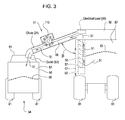
FIG. 3 shows the machine for generating electrical energy installed on the chute of a combine or harvester. - In accordance with one embodiment,
FIG. 1 and FIG. 2 show an alternator, generator or amachine 11 for generating electrical energy. Themachine 11 comprises ahousing 13 and ashaft 17 rotatable about anaxis 15 with respect to thehousing 13. One or moreouter bearings 12 and one or moreinner bearings 26 are secured to thehousing 13 and are associated with theshaft 17 to support theshaft 17 and allow rotation of theshaft 17 with respect to thehousing 13. Although four bearings (12, 26) are illustrated in the embodiment ofFIG. 2 , two or more bearings spaced apart can be used in alternate embodiments, and such alternate embodiments fall within the scope of the claims. - An
impeller 20 hasblades 22 for rotation with theshaft 17 about theaxis 15 in response to receipt of material (e.g., harvested material) from achute 24. Afirst end 14 of theshaft 17 is associated with afirst generator assembly 10, whereas asecond end 114 of theshaft 17 is associated with asecond generator assembly 110.FIG. 1 is shown as a cross-section from the perspective of facing thesecond end 114 of theshaft 17. - A
first generator assembly 10 comprisesfirst stator windings 28 associated with thehousing 13 and a first magnet 16 (e.g., first magnet assembly) affixed to theshaft 17, such that if theimpeller 20 rotates an electromagnetic signal energizes thefirst stator windings 28 in response to the flow of material through thechute 24. In thefirst stator windings 28, the electromagnetic signal is induced by the rotating magnetic field of the first magnet 16. Theshaft 17 has ashaft axis 15 that is generally perpendicular to a direction of flow of the material through thechute 24. - In one embodiment, the
first stator windings 28 may be inserted between one or moreinterior protrusions 18 of thehousing 13. Thefirst stator windings 28 may be secured to thehousing 13 via one ormore protrusions 18, or otherwise attached to thehousing 13 and electrically insulated from thehousing 13. - In one configuration, the first magnet 16 comprises a first magnet assembly with a set of magnets attached to the
shaft 17 and spaced apart at differential radial angles with respect to theshaft 17. For instance, the first magnet 16 may comprise a first magnet assembly with sets of magnets spaced apart on theshaft 17 at different axial positions and at different radial positions, as illustrated inFIG. 2 . - Referring to
FIG. 2 , asecond generator assembly 110 comprisessecond stator windings 128 associated with thehousing 13 and a second magnet 116 (e.g., second magnet assembly) affixed to theshaft 17, such that if theimpeller 20 rotates an electromagnetic signal energizes thesecond stator windings 128 based on the flow of material through thechute 24. In thesecond stator windings 128, the rotating magnetic field of thesecond magnet 116 induces the electromagnetic signal. - In one embodiment, the
second stator windings 128 may be inserted between one or moreinterior protrusions 18 of the housing. Thesecond stator windings 128 may be secured to thehousing 13 via one ormore protrusions 18, or otherwise attached to thehousing 13 and electrically insulated from thehousing 13. - In one configuration, the
second magnet 116 comprises a second magnet assembly with a set of magnets attached to theshaft 17 and spaced apart at differential radial angles with respect to theshaft 17. For instance, thesecond magnet 116 may comprise a first magnet assembly with sets of magnets spaced apart on theshaft 17 at different axial positions and at different radial positions, as illustrated inFIG. 2 . -
FIG. 2 shows a cross section of themachine 11 taken along reference line 2-2 ofFIG. 1 , where theimpeller 20 andblades 22 are shown in perspective view, and where associated circuitry is shown in a block diagram. - With respect to the
impeller 20 and itsblades 22, theimpeller 20 may be configured as a paddle wheel where theimpeller blades 22 are tilted at an angular offset α with respect to arotational axis 15 of theshaft 17. For example, theblades 22 of theimpeller 20 are arranged in a paddle wheel configuration with slopedblades 22, where each of the slopedblades 22 has a slope angle α with respect to a rotational axis of theshaft 17 to facilitate passage or drainage of the material through thechute 24 by gravity and/or a motive force provided by an auger (e.g., 55 inFIG. 3 ). As best illustrated inFIG. 1 , thehousing 13 around theimpeller 20 has aninlet 66 and anoutlet 62 for attachment to thechute 24, wherearrow 51 illustrates the direction of flow of the material through thechute 24 around theblades 22. As illustrated the housing section (e.g., 13) around theimpeller 20 has a larger cross-sectional area than the remainder of thechute 24, although theimpeller 20 can be made more compact with a cross-sectional area that is approximately equal to the remainder of thechute 24 in alternate configurations. -
FIG. 2 illustrates circuitry associated with the alternator, generator ormachine 11 for generating electrical energy in a block diagram. InFIG. 2 , the block diagram portion shows afirst rectifier 30 coupled to thefirst stator windings 28 for converting the electromagnetic signal (e.g., alternating current signal) into a direct current signal. Thefirst stator windings 28 may comprise one or more coils or inductors that are connected in series or in parallel, for example. - An optional
first filter 32 is coupled to thefirst rectifier 30. The optional filter is shown as dashed lines to indicate that it is optional and may be deleted in alternate embodiments. In turn, the first filter 32 (or first rectifier 30) is coupled to a firstpower management module 34. The optional first filter 32 (if present) is adapted to filter the direct current signal. - The first
power management module 34 is configured for storing, processing, switching, load matching, impedance adjusting, voltage setting, current setting, or otherwise managing the direct current signal. In one embodiment, a first output of a direct current output signal from the firstpower management module 34 may be coupled to anoptional load 59. Theoptional load 59 may comprise one or more of the following: a battery, an energy storage device, a sensor, an electrical circuit, or an accessory. - In one embodiment, the
first rectifier 30 comprises a bridge rectifier, a full-wave rectifier, a half-wave rectifier, or a circuit of one or more diodes. A half-wave rectifier comprises a diode that is placed in series with one of the terminals from thefirst stator windings 28 such that a positive or negative portion (e.g., positive sine wave portion) of the electromagnetic signal can be provided to the firstpower management module 34, thepower management module 234, or an optional load 59 (e.g., battery), for example. - In one configuration, the
first filter 32 comprises one or more of the following: a capacitor, an electrolytic capacitor, a low pass filter that rejects electromagnetic signals in a band above direct current or zero Hertz, or a tuned network of capacitors and inductors. For instance, the first filter 32 (e.g., capacitor) is placed in parallel across the output of thefirst rectifier 30 or one output terminal of thefirst rectifier 30 and a terminal of thefirst stator windings 28. Thefirst filter 32 is optional as indicated by the dashed lines inFIG. 2 . - A
second rectifier 130 is coupled to thesecond stator windings 128 for converting the electromagnetic signal (e.g., alternating current signal) into a direct current signal. Thesecond stator windings 128 may comprise one or more coils or inductors connected in series or parallel, for example. An optionalsecond filter 132 is coupled to thesecond rectifier 130. Thesecond filter 132 is shown in dashed lines because it is optional and can be deleted. In turn, the optional second filter 132 (or second rectifier 130) is coupled to a secondpower management module 134. Thesecond filter 132 is adapted to filter the direct current signal. The secondpower management module 134 is configured for storing or managing the direct current signal. - In one embodiment, the
second rectifier 130 comprises a bridge rectifier, a full-wave rectifier, a half-wave rectifier, or a circuit of one or more diodes. A half-wave rectifier comprises a diode that is placed in series with one of the terminals from the second stator windings such that a positive or negative portion (e.g., positive sine wave portion) of the electromagnetic signal can be provided to the power management module or a load (e.g., battery), for example. - In one configuration, the
second filter 132 comprises one or more of the following: a capacitor, an electrolytic capacitor, a low pass filter that rejects electromagnetic signals in a band above direct current or zero Hertz, or a tuned network of capacitors and inductors. For instance, the second filter 132 (e.g., capacitor) is placed in parallel across the output of the rectifier or one output terminal of thesecond rectifier 130 and a terminal of thesecond stator windings 128. Thesecond filter 132 is optional as indicated by the dashed lines inFIG. 2 . - The first
power management module 134 is configured for storing, processing, switching, load matching, impedance adjusting, voltage setting, current setting, or otherwise managing the direct current signal. In one embodiment, a second output of a direct current output signal from second firstpower management module 134 may be coupled to an optional load 59 (e.g., battery or energy storage device). - In one embodiment, the
power manager 234 or the power management module comprises the firstpower management module 34, the secondpower management module 134, or both. In one illustrative configuration, thepower manager 234 may comprise one or more switches that connects or disconnects both output terminals of thefirst filter 32, thesecond filter 132, or both to anelectrical load 59 or circuit (e.g., battery, sensor or accessory). For example, the switches may be configured as a single pole, single throw switch or a double pole, single throw switch to manage the output from either thefirst filter 30, or thesecond filter 132. In one configuration, thepower manager 234 or the power management module may select alternately the output of thefirst rectifier 30 and thesecond rectifier 132, where each is a half-wave rectifier of opposite polarity output, to output a full-wave rectified output signal to an electrical load. - Alternatively, the
power manager 234 or its switches may be configured to place or configure the generator output terminals of thefirst generator assembly 10 and thesecond generator assembly 110 in parallel or in series with each other; particularly, where each of thefirst rectifier 30 and thesecond rectifier 130 comprise full-wave or bridge rectifiers. The generator output terminals refer to the output terminals of thefirst rectifier 30, thesecond rectifier 130, with or without filters (32, 132). - Where the rectifiers (30, 130) are full-wave rectifiers, the
power manager 234 may place the first generator output terminal of thefirst generator assembly 10 in parallel with the second generator output terminal of thesecond generator assembly 110 to produce greater current or maximum generated current at the output for application to an electrical load. Alternatively, thepower manager 234 may place the first generator output terminal of thefirst generator assembly 10 in series with the second generator output terminal of thesecond generator assembly 110 to produce a greater voltage or a maximum generated voltage at the output for application to anelectrical load 59. From time-to-time based on fluctuations in theload 59 or the nature of theload 59, thepower manager 234 may switch between the above series and parallel configurations to match the voltage or current requirements of the electrical load to the corresponding electrical characteristics of the generated electrical energy. For example, theelectrical load 59 is a battery with a nominal voltage of X volts direct current, thepower manager 234 may need to place the generator output terminals of thefirst generator assembly 10 and thesecond generator assembly 110 in series to generate a voltage equal to or greater than X to charge the battery, assuming the current output is adequate, for instance. - In one embodiment, the direct current signal at the output of the
power manager 234 is coupled to anoptional load 59 an electrical energy storage device. In another embodiment, the direct current signal or the power management module can be coupled to a sensor as an optional load to provide electrical energy for the sensor as anelectrical load 59. - The
optional load 59 is optional as is indicated by the dashed lines. In an alternate embodiment, the optional load may be deleted. For example, if theoptional load 59 is deleted, the outputted direct current signal (from the power manager 234) has a voltage or current that is indicative of a rate of flow of material through thechute 24 such that the machine for generating electrical energy functions as a material flow sensor, a material flow rate sensor, a grain flow sensor, or a grain flow rate sensor. For example, the higher the output voltage (from output terminal(s) of the power manager 234), the greater is the flow of harvested material through themachine 11 via the inlet and outlet. - In
FIG. 3 , acombine 60 or harvester harvests a crop, plant or other material. Thecombine 60 or harvester transfers the harvested material from thecombine 60 or harvester to a receivingvehicle 61, such as a cart 58 (e.g., grain cart), via thechute 24. In one embodiment, thecombine 60 or harvester has anauger 55 for conveyingmaterial 63 from a bin 82 (e.g., grain tank) to the receivingvehicle 61 via thechute 24. For example, the harvested material comprises an agricultural material selected from the group consisting of corn, grain, soybeans, oilseed, wheat, barley, oats, rice, cotton, fiber, stover, forage or other plant material. In thecombine 60, thematerial height 63 or cross-sectional profile of the material is illustrated by the alternating dotted-and-dashed line. Apropulsion unit 53 is capable of rotating theauger 55 to convey the material from thebin 82 in the direction shown by thearrows 51. Theauger 55 is mounted in and can rotate with respect tochannel 57. As shown thechute 24 makes an angle β with respect to avertical axis 67 or the side of thecombine 60. Thecombine 60 or harvester and thegrain cart 61 may havewheels 81, such that thecombine 60 or harvester may both harvest and transfer harvested material to the receivingvehicle 61 while both the combine 60 (or harvester) and the receivingvehicle 61 are moving along similar coordinated or parallel paths in substantially the same direction of travel. In the interior 83 of thecart 58, thematerial height 56 or cross-sectional profile of the material is illustrated by the alternating dotted-and-dashed line. - In alternate embodiments, the machine (11) may be embodied as a combination of any independent claim and one or more features of any dependent claim thereon, where any features from one or more dependent claims may be incorporated cumulatively or separately into any independent claim upon which the dependent claims or its features depend or are otherwise supported by the disclosure.
- Having described the preferred embodiment, it will become apparent that various modifications can be made without departing from the scope of the invention as defined in the accompanying claims.
Claims (12)
- A machine for generating electrical energy, the machine comprising:a housing;a shaft rotatable with respect to the housing;an impeller with blades for rotation with the shaft in response to receipt of material from a chute;a first generator assembly comprising first stator windings associated with the housing and a first magnet affixed to the shaft, such that if the impeller rotates an electromagnetic signal energizes the first stator windings based on the flow of material through the chute.
- The machine according to claim 1 further comprising:a first rectifier coupled to the first stator windings for converting the electromagnetic signal into a direct current signal;a first filter for filtering the direct current signal; anda first power management module for storing or managing the direct current signal.
- The machine according to claim 2 wherein the direct current signal is coupled to an electrical energy storage device.
- The machine according to claim 2 wherein the direct current signal has a voltage or current that is indicative of a rate of flow of material through the chute.
- The machine according to claim 2 wherein the direct current signal or the power management module is coupled to a sensor.
- The machine according to claim 1 further comprising:a second generator assembly comprising second stator windings associated with the housing and a second magnet affixed to the shaft, such that if the impeller rotates an electromagnetic signal energizes the second stator windings based on the flow of material through the chute.
- The machine according to claim 6 further comprising:a second rectifier coupled to the second stator windings for converting the electromagnetic signal into a direct current signal;a second filter for filtering the direct current signal;a second power management module for storing or managing the direct current signal.
- The machine according to claim 1 wherein the material comprises an agricultural material selected from the group consisting of corn, grain, soybeans, oilseed, wheat, and barley.
- The machine according to claim 1 wherein the shaft has a shaft axis that is generally perpendicular to a direction of flow of the material through the chute.
- The machine according to claim 1 wherein the blades of the impeller are arranged in a paddle wheel configuration with sloped blades, where each of the sloped blades has a slope angle with respect to a rotational axis of the shaft to facilitate passage or drainage of the material through the chute by gravity.
- The machine according to claim 1 wherein a plurality of bearings support the shaft in the housing for rotation of the shaft with respect to the housing.
- A harvester for harvesting an agricultural material, the harvester comprising a chute for unloading or transferring the agricultural material from the harvester and a machine for generating electrical energy associated with the chute.
Applications Claiming Priority (1)
| Application Number | Priority Date | Filing Date | Title |
|---|---|---|---|
| US13/849,759 US9810221B2 (en) | 2013-03-25 | 2013-03-25 | Machine for generating electrical energy |
Publications (2)
| Publication Number | Publication Date |
|---|---|
| EP2784917A2 true EP2784917A2 (en) | 2014-10-01 |
| EP2784917A3 EP2784917A3 (en) | 2015-07-29 |
Family
ID=50179478
Family Applications (1)
| Application Number | Title | Priority Date | Filing Date |
|---|---|---|---|
| EP14156147.2A Withdrawn EP2784917A3 (en) | 2013-03-25 | 2014-02-21 | Machine for generating electrical energy |
Country Status (2)
| Country | Link |
|---|---|
| US (1) | US9810221B2 (en) |
| EP (1) | EP2784917A3 (en) |
Cited By (1)
| Publication number | Priority date | Publication date | Assignee | Title |
|---|---|---|---|---|
| CN105781896A (en) * | 2016-04-20 | 2016-07-20 | 陶原 | A mast-type wind power generation device |
Families Citing this family (4)
| Publication number | Priority date | Publication date | Assignee | Title |
|---|---|---|---|---|
| NL2019028B1 (en) | 2017-05-31 | 2018-12-11 | Kinetron Bv | Turbine flow meter, assembly, and method for measuring at least one flow characteristic |
| WO2018222040A1 (en) * | 2017-05-31 | 2018-12-06 | Kinetron B.V. | Turbine flow meter, assembly, and method for measuring at least one flow characteristic |
| US20240198810A1 (en) * | 2018-04-26 | 2024-06-20 | Positec Power Tools (Suhou)Co., Ltd | Autonomous gardening apparatus |
| CN110925152B (en) * | 2019-12-06 | 2021-08-17 | 珠海阔朗科技有限公司 | Mixing building power generation facility for energy recuperation |
Family Cites Families (7)
| Publication number | Priority date | Publication date | Assignee | Title |
|---|---|---|---|---|
| US3771531A (en) * | 1972-07-17 | 1973-11-13 | Fmc Corp | Legume harvester with automatic dump hopper |
| DE2501321A1 (en) | 1975-01-15 | 1976-07-22 | Claas Maschf Gmbh Geb | Flow rate measurement for EG grain - loose goods tipped down chute to turn wheel attached to tachogenerator |
| AU2004100026A4 (en) | 2003-01-20 | 2004-02-26 | Brian Investments Pty Ltd | Granular flow deflector and power regenerator |
| JP2005083195A (en) * | 2003-09-04 | 2005-03-31 | Honda Motor Co Ltd | Power supply |
| MX2007009324A (en) | 2005-02-02 | 2007-11-14 | Magnetic Applic Inc | Pulse generator for a controlled rectifier. |
| US20100237626A1 (en) | 2009-03-23 | 2010-09-23 | Hydrovolts, Inc. | Hinged-blade cross-axis turbine for hydroelectric power generation |
| JP2010252742A (en) | 2009-04-28 | 2010-11-11 | Iseki & Co Ltd | Hybrid combine |
-
2013
- 2013-03-25 US US13/849,759 patent/US9810221B2/en active Active
-
2014
- 2014-02-21 EP EP14156147.2A patent/EP2784917A3/en not_active Withdrawn
Non-Patent Citations (1)
| Title |
|---|
| None |
Cited By (1)
| Publication number | Priority date | Publication date | Assignee | Title |
|---|---|---|---|---|
| CN105781896A (en) * | 2016-04-20 | 2016-07-20 | 陶原 | A mast-type wind power generation device |
Also Published As
| Publication number | Publication date |
|---|---|
| US9810221B2 (en) | 2017-11-07 |
| EP2784917A3 (en) | 2015-07-29 |
| US20140286802A1 (en) | 2014-09-25 |
Similar Documents
| Publication | Publication Date | Title |
|---|---|---|
| US9810221B2 (en) | Machine for generating electrical energy | |
| US11351360B2 (en) | Transcutaneous energy transfer systems | |
| US10881773B2 (en) | Transcutaneous energy transfer systems | |
| US10547182B2 (en) | Electric operating machine | |
| US8957631B2 (en) | Self-powered wireless induction sensor | |
| ES2410179T3 (en) | Protection system for an electric generator, a wind turbine and its use | |
| CN101331503B (en) | Systems and methods for receiving and managing power in wireless devices | |
| EP2784916B1 (en) | Device for generating electrical energy or sensing material flow | |
| EP2266183A2 (en) | Passive over/under voltage control and protection for energy storage devices associated with energy harvesting | |
| US20160254725A1 (en) | Generator assembly and bearing equipped with the same | |
| GB2536183A (en) | Device for separately transmitting multiple electric powers on a turbine engine rotor | |
| WO2010042052A1 (en) | Method and apparatus for supplying energy to an implant | |
| US10312797B1 (en) | Zero power startup circuit for vibrational energy harvesting | |
| US8213201B2 (en) | Motion activated amplifier | |
| CN113614367A (en) | Energy supply for sensors in wind turbines | |
| Hendry et al. | Piezoelectric-based Battery Charging on Multirotor Drone for Modern Farming: A Concept Model | |
| CN120691558A (en) | Self-powered system for sensors on rotating shafts under variable temperature and variable speed coupling conditions | |
| US8324753B2 (en) | Method and apparatus for powering a device | |
| Mleczko | RF-Energy Harvesting helps to Power IoT | |
| CN107934699A (en) | A kind of agricultural chemical spraying machine jet pipe electric retractable system | |
| HK1221823B (en) | Energy harvesting device |
Legal Events
| Date | Code | Title | Description |
|---|---|---|---|
| 17P | Request for examination filed |
Effective date: 20140221 |
|
| AK | Designated contracting states |
Kind code of ref document: A2 Designated state(s): AL AT BE BG CH CY CZ DE DK EE ES FI FR GB GR HR HU IE IS IT LI LT LU LV MC MK MT NL NO PL PT RO RS SE SI SK SM TR |
|
| AX | Request for extension of the european patent |
Extension state: BA ME |
|
| PUAI | Public reference made under article 153(3) epc to a published international application that has entered the european phase |
Free format text: ORIGINAL CODE: 0009012 |
|
| PUAL | Search report despatched |
Free format text: ORIGINAL CODE: 0009013 |
|
| AK | Designated contracting states |
Kind code of ref document: A3 Designated state(s): AL AT BE BG CH CY CZ DE DK EE ES FI FR GB GR HR HU IE IS IT LI LT LU LV MC MK MT NL NO PL PT RO RS SE SI SK SM TR |
|
| AX | Request for extension of the european patent |
Extension state: BA ME |
|
| RIC1 | Information provided on ipc code assigned before grant |
Ipc: G01F 1/10 20060101ALI20150619BHEP Ipc: F03G 3/04 20060101ALI20150619BHEP Ipc: H02K 11/04 20060101ALN20150619BHEP Ipc: H02K 7/18 20060101AFI20150619BHEP |
|
| STAA | Information on the status of an ep patent application or granted ep patent |
Free format text: STATUS: THE APPLICATION IS DEEMED TO BE WITHDRAWN |
|
| 18D | Application deemed to be withdrawn |
Effective date: 20160130 |