EP2784912A1 - Wiper motor - Google Patents
Wiper motor Download PDFInfo
- Publication number
- EP2784912A1 EP2784912A1 EP11876134.5A EP11876134A EP2784912A1 EP 2784912 A1 EP2784912 A1 EP 2784912A1 EP 11876134 A EP11876134 A EP 11876134A EP 2784912 A1 EP2784912 A1 EP 2784912A1
- Authority
- EP
- European Patent Office
- Prior art keywords
- armature
- gear housing
- magnet
- disposed
- armature shaft
- Prior art date
- Legal status (The legal status is an assumption and is not a legal conclusion. Google has not performed a legal analysis and makes no representation as to the accuracy of the status listed.)
- Withdrawn
Links
- 230000007246 mechanism Effects 0.000 claims abstract description 39
- 230000009467 reduction Effects 0.000 claims abstract description 39
- 230000002093 peripheral effect Effects 0.000 claims description 16
- 238000004804 winding Methods 0.000 claims description 8
- 238000001514 detection method Methods 0.000 description 6
- 210000000078 claw Anatomy 0.000 description 4
- 239000011810 insulating material Substances 0.000 description 3
- RYGMFSIKBFXOCR-UHFFFAOYSA-N Copper Chemical compound [Cu] RYGMFSIKBFXOCR-UHFFFAOYSA-N 0.000 description 2
- XEEYBQQBJWHFJM-UHFFFAOYSA-N Iron Chemical compound [Fe] XEEYBQQBJWHFJM-UHFFFAOYSA-N 0.000 description 2
- 230000008859 change Effects 0.000 description 2
- 230000003247 decreasing effect Effects 0.000 description 2
- 239000000463 material Substances 0.000 description 2
- 239000007769 metal material Substances 0.000 description 2
- 239000011347 resin Substances 0.000 description 2
- 229920005989 resin Polymers 0.000 description 2
- 229910001369 Brass Inorganic materials 0.000 description 1
- 229930182556 Polyacetal Natural products 0.000 description 1
- 239000000853 adhesive Substances 0.000 description 1
- 230000001070 adhesive effect Effects 0.000 description 1
- 229910052782 aluminium Inorganic materials 0.000 description 1
- XAGFODPZIPBFFR-UHFFFAOYSA-N aluminium Chemical compound [Al] XAGFODPZIPBFFR-UHFFFAOYSA-N 0.000 description 1
- 239000010951 brass Substances 0.000 description 1
- 239000004020 conductor Substances 0.000 description 1
- 229910052802 copper Inorganic materials 0.000 description 1
- 239000010949 copper Substances 0.000 description 1
- 230000002542 deteriorative effect Effects 0.000 description 1
- 230000000694 effects Effects 0.000 description 1
- 230000004907 flux Effects 0.000 description 1
- 239000004519 grease Substances 0.000 description 1
- 238000010438 heat treatment Methods 0.000 description 1
- 229910052742 iron Inorganic materials 0.000 description 1
- 238000000034 method Methods 0.000 description 1
- 238000000465 moulding Methods 0.000 description 1
- 230000000149 penetrating effect Effects 0.000 description 1
- 229920006324 polyoxymethylene Polymers 0.000 description 1
- 230000003449 preventive effect Effects 0.000 description 1
- 230000008569 process Effects 0.000 description 1
- 230000004043 responsiveness Effects 0.000 description 1
- 238000005096 rolling process Methods 0.000 description 1
- 239000000758 substrate Substances 0.000 description 1
- 229920001187 thermosetting polymer Polymers 0.000 description 1
Images






Classifications
-
- H—ELECTRICITY
- H02—GENERATION; CONVERSION OR DISTRIBUTION OF ELECTRIC POWER
- H02K—DYNAMO-ELECTRIC MACHINES
- H02K7/00—Arrangements for handling mechanical energy structurally associated with dynamo-electric machines, e.g. structural association with mechanical driving motors or auxiliary dynamo-electric machines
- H02K7/10—Structural association with clutches, brakes, gears, pulleys or mechanical starters
- H02K7/116—Structural association with clutches, brakes, gears, pulleys or mechanical starters with gears
-
- H—ELECTRICITY
- H02—GENERATION; CONVERSION OR DISTRIBUTION OF ELECTRIC POWER
- H02K—DYNAMO-ELECTRIC MACHINES
- H02K11/00—Structural association of dynamo-electric machines with electric components or with devices for shielding, monitoring or protection
- H02K11/20—Structural association of dynamo-electric machines with electric components or with devices for shielding, monitoring or protection for measuring, monitoring, testing, protecting or switching
- H02K11/21—Devices for sensing speed or position, or actuated thereby
-
- H—ELECTRICITY
- H02—GENERATION; CONVERSION OR DISTRIBUTION OF ELECTRIC POWER
- H02K—DYNAMO-ELECTRIC MACHINES
- H02K11/00—Structural association of dynamo-electric machines with electric components or with devices for shielding, monitoring or protection
- H02K11/20—Structural association of dynamo-electric machines with electric components or with devices for shielding, monitoring or protection for measuring, monitoring, testing, protecting or switching
- H02K11/21—Devices for sensing speed or position, or actuated thereby
- H02K11/215—Magnetic effect devices, e.g. Hall-effect or magneto-resistive elements
-
- H—ELECTRICITY
- H02—GENERATION; CONVERSION OR DISTRIBUTION OF ELECTRIC POWER
- H02K—DYNAMO-ELECTRIC MACHINES
- H02K11/00—Structural association of dynamo-electric machines with electric components or with devices for shielding, monitoring or protection
- H02K11/30—Structural association with control circuits or drive circuits
- H02K11/38—Control circuits or drive circuits associated with geared commutator motors of the worm-and-wheel type
-
- H—ELECTRICITY
- H02—GENERATION; CONVERSION OR DISTRIBUTION OF ELECTRIC POWER
- H02K—DYNAMO-ELECTRIC MACHINES
- H02K23/00—DC commutator motors or generators having mechanical commutator; Universal AC/DC commutator motors
- H02K23/66—Structural association with auxiliary electric devices influencing the characteristic of, or controlling, the machine, e.g. with impedances or switches
-
- H—ELECTRICITY
- H02—GENERATION; CONVERSION OR DISTRIBUTION OF ELECTRIC POWER
- H02K—DYNAMO-ELECTRIC MACHINES
- H02K7/00—Arrangements for handling mechanical energy structurally associated with dynamo-electric machines, e.g. structural association with mechanical driving motors or auxiliary dynamo-electric machines
- H02K7/10—Structural association with clutches, brakes, gears, pulleys or mechanical starters
- H02K7/116—Structural association with clutches, brakes, gears, pulleys or mechanical starters with gears
- H02K7/1163—Structural association with clutches, brakes, gears, pulleys or mechanical starters with gears where at least two gears have non-parallel axes without having orbital motion
- H02K7/1166—Structural association with clutches, brakes, gears, pulleys or mechanical starters with gears where at least two gears have non-parallel axes without having orbital motion comprising worm and worm-wheel
Definitions
- the present invention relates to a motor with speed reduction mechanism.
- a wiper motor is used as a driving source for periodically swinging a wiper arm (see for example Patent Document 1).
- This wiper motor has: a motor unit having brushes and an armature; and a speed reduction mechanism unit for reducing the speed of rotation of the armature of the motor unit.
- the speed reduction mechanism unit is provided with a control device for controlling the rotation of the armature, thereby controlling a position and a speed of the wiper arm.
- Patent Document 1 Japanese Patent Application Laid-Open Publication No. 2009-189093
- the present invention has been made in order to solve the above-mentioned problems, and an object of the present invention is to provide a wiper motor improved in weight and size, and improved in wiping accuracy.
- a wiper motor comprises : a yoke; a magnet formed with at least four poles in which different magnetic poles are alternately disposed on an inner peripheral surface of the yoke; an armature including an armature shaft which has one end rotatably supported by a bottom portion of the yoke, a commutator which is fixed to the armature shaft, and a core which is fixed to the armature shaft and around which a winding wire is wound, wherein the armature is rotatably disposed on an inner side of the magnet; two brushes slidably contacting with the commutator, the brushes being disposed so as to be spaced apart from each other at intervals of 90 degrees; a speed reduction mechanism unit having an output shaft for transmitting the rotation of the armature shaft by meshing with a worm formed on the armature shaft; a gear housing connected to the yoke, the gear housing being formed with a speed reduction mechanism
- a wiper motor comprises : a case; a magnet formed with at least four poles in which different magnetic poles are alternately disposed on an inner peripheral surface of the case; an armature including an armature shaft which is rotatably supported by the case, a commutator which is fixed to the armature shaft, and a core which is fixed to the armature shaft and around which a winding wire is wound, wherein the armature is rotatably disposed on an inner side of the magnet; two brushes slidably contacting with the commutator, the brushes being disposed so as to be spaced apart from each other at intervals of 90 degrees; a speed reduction mechanism unit accommodated in the case, the speed reduction mechanism unit having an output shaft meshing with a worm formed on the armature shaft to transmit the rotation of the armature shaft; a magnet attached to the output shaft; an absolute position detecting sensor disposed so as to face the magnet; and a control board having the absolute position detecting sensor attached thereto, the
- the output shaft is formed with a fixing part to which a swinging member is directly or indirectly fixed.
- the wiper motor which can rotate its armature in a forward direction and a reverse direction by using a four-pole magnet and two brushes, is provided with an angle sensor, it is possible to provide a wiper motor improved in weight and size, and improved in wiping accuracy.
- a wiper motor 1 as a motor with speed reduction mechanism includes: as shown in FIGS. 1 and 2A , a motor unit 10 for performing a rotating operation with electric current; and a speed reduction mechanism unit 25 for reducing the speed of rotation of the motor unit 10 and transmitting the speed reduced rotation to an output shaft 24.
- the motor unit 10 includes a yoke (first case) 13 which is formed into a bottomed cylindrical shape, at least four magnets 11 are fixed to an inner circumferential surface thereof, a gear housing 26 is fixed to one end surface thereof, and a shaft bearing part 12 is fixed to the other end surface thereof.
- a yoke (first case) 13 which is formed into a bottomed cylindrical shape, at least four magnets 11 are fixed to an inner circumferential surface thereof, a gear housing 26 is fixed to one end surface thereof, and a shaft bearing part 12 is fixed to the other end surface thereof.
- the motor unit 10 includes an armature shaft 14 having one end rotatably supported by the bearing part 12 and having a worm part 14a formed at its tip, a commutator 15 fixed to the armature shaft 14, an armature core 16 adjacent to the commutator 15 and fixed to the armature shaft 14, and a winging wire part 17 wound around the armature core 16, wherein an armature 18 is rotatably disposed on the inner side of the plurality of magnets 11.
- the motor unit 10 has a brush holder unit 19 including a plurality of brushes 20 and 20 slidably supporting the commutator 15 with the rotation of the armature 18, and brush holders 21 and 21 holding the respective brushes 20 and 20.
- the speed reduction mechanism unit 25 includes a worm wheel part 25a for reducing the speed of rotation of the motor unit 10, and the gear housing (second case) 26 having a bottomed speed reduction mechanism accommodating part 26f in which the worm wheel part 25a is accommodated. Furthermore, the speed reduction mechanism unit 25 further includes a gear housing cover 29 covering an opening of the speed reduction mechanism accommodating part 26f, and a brush holder accommodating part 26d in which the brush holder unit 19 is accommodated.
- the worm wheel part 25a includes the output shaft 24 for reducing the speed of rotation of the armature 18 of the motor unit 10 and transmitting the speed reduced rotation, and the brush holder accommodating part 26d is cylindrically formed and is integrally molded with the gear housing 26.
- the gear housing 26 and the gear housing cover (third case) 29 are fixed to each other by a plurality of screws 40.
- the wiper motor having an integrated case is constructed by mechanically connecting the yoke (first case) 13, the gear housing (second case) 26, and the gear housing cover (third case) 29 to each other.
- the worm wheel part 25a included in the speed reduction mechanism unit 25 is made of resin such as polyacetal, into a disk shape, and has an outer peripheral surface formed with an engaging part 25b engaged with the worm part 14a of the armature shaft 14.
- the output shaft 24 is integrally mounted at the center of rotation of the worm wheel part 25a.
- a cylindrical (button-shaped) magnet 25c is attached so that its rotation center is axially aligned with the rotation center of the output shaft 24. Furthermore, the magnet 25c is polarized so as to have: an N pole in a range of 180 degrees in one circumferential direction defined around its rotation center as a center; and an S pole in a range of 180 degrees in the other circumferential direction.
- a Hall IC for absolute position detection 29d is provided on a control board 29c which will be further described below.
- the Hall IC for absolute position detection 29d is configured to detect the change of magnetic field generated by the magnet 25c with the rotation of the output shaft 24, and to convert it into angle data. And on the basis of a signal generated by the Hall IC for absolute position detection 29d so as to correspond to the change of magnetic field generated by the magnet 25c, an angle of a current position of a wiper arm on a windshield (not shown) from its specific position such as lower reversing position or stop position of the wiper device attached to the top of the output shaft 24 of the motor with speed reduction mechanism is calculated.
- the magnet 25c is integrally fixed to the base end of the output shaft, a swinging member 43 such as wiper arm or motor crank is directly fixed to one end of the output shaft by a fixing member 44 such as nut so as not to move around it, and an intermediate portion of the output shaft 24 is supported by an output shaft support part 26g formed as part of the gear housing 26 (second case) so as to extend in an axial direction.
- the wiper motor 1 Since the output shaft 24 is prevented from being moved in the axial direction by this part, the movement of the wiper arm or the motor crank can be detected with accuracy by the Hall IC for absolute position detection 29d. Also, since the wiper motor 1 is made up of a four-pole wiper motor, the wiper motor 1 can be reduced in size, and inertia of the wiper motor 1 can be reduced. Therefore, since the loss of the wiper motor 1, such as balance in rotation of the armature 18, is reduced, and responsiveness of control and accuracy of wiping control can be enhanced.
- the armature shaft 14 can be reduced in length, and the wiper motor 1 can be reduced in size.
- the yoke 13 is integrally molded by press working from a plate material into a bottomed cylindrical shape, and a magnet fixing part 13a in which the plurality of magnets 11 are fixed onto its inner peripheral surface and a yoke connecting part 13d integrally connected to the magnet fixing part 13a are formed in the yoke 13. And in the yoke connecting part 13d, paired curved parts 13b and paired flat surface parts 13c alternately connected so as to be formed into an elliptical shape seen from an axial direction. On the end face of the yoke 13, a flange shaped fixing part 13e is formed, and the gear housing 26, which will be described further below, is fixed to the flange shaped fixing part 13e.
- the yoke connecting part 13d is formed so that an arc diameter is gradually widened from the magnet fixing part 13a toward the yoke end face.
- four magnets 11 are fixed with an adhesive or the like so that two N poles and two S poles, which are different magnetic poles, are alternately disposed, that is, the same poles face each other.
- the armature shaft 14 has one end rotatably supported by the bearing part 12 of the yoke 13, and the armature shaft 14 is disposed on the inner side of the four magnets 11.
- the armature shaft 14 has the other end formed with the worm part 14a formed into a spiral shape by component rolling.
- the commutator 15 includes an insulating cylindrical part 15a formed into a cylindrical shape and made of insulating material such as thermosetting resin, and a plurality of segment parts 15b spaced at predetermined intervals in a circumferential direction on an outer peripheral surface of the insulating cylindrical part 15a and made of electrical conducting material such as copper.
- the commutator 15 is fixed to the armature shaft 14 so that the inner peripheral surface of the insulating cylindrical part 15a is engaged with the outer peripheral surface of the armature shaft 14.
- a coil connecting part 15c is formed, and each coil connecting part 15c is connected to a coil 17a.
- the armature core 16 is formed into a cylindrical shape by stacking in layers predetermined numbers of core substrates which are stamped out by press working, and the armature core 16 includes a shaft fixing part to which the armature shaft 14 is fixed, and eighteen teeth parts radially extending from the shaft fixing part.
- a coil 17a made of copper wire is wound around the armature core 16.
- One end of the coil 17a is fixed to the coil connecting part 15c of one of the segment parts 15b, and the coil 17a is wound by lap winding between predetermined teeth parts a plurality of times.
- the other end of the coil 17a is fixed to the coil connecting part 15c of another segment part 15b.
- a connecting line (electric current supply line) 17b is connected to one segment part 15b facing another segment part 15b.
- the coil 17a is wound around the armature core 16 by repeating a process of winding the coil 17a about each teeth part.
- the brush holder unit 19 includes a base part 19c in which paired curved parts 19a and paired flat surface parts 19b are alternately connected so as to be formed into an elliptical shape.
- the base part 19c is formed with an opening portion 19c1 through which the armature shaft 14 is penetrated, and a fixing opening portion 19c2 through which a screw 41 is penetrated, thereby fixing the brush holder unit 19 and the gear housing 26.
- the brush holders 21 and 21 made of metal material such as brass are fixed to the base part 19c, and two brushes 20 and 20 are disposed in the brush holders 21 and 21 so as to be able to get close to and away from the commutator 15.
- two brushes 20 and 20 are located around the rotation center O of the armature 18 at intervals of approximately 90 degrees.
- the brush holders 21 are disposed in the vicinity of one of the paired flat surface parts 19b of the base part 19c. Fixing claws 21a of the brush holders 21 are inserted in a brush holder fixing part 19c3 formed in the base part 19c, and the fixing claws 21a are folded on the back surface side of the base part 19c, so that the brush holder 21 is fixed to the base part 19c.
- the brush holder unit 19 includes a brush holder guide wall 19d and a brush terminal connecting part 19e, and the brush holder guide wall 19d is formed into a shape approximately the same as the outer shape (elliptical shape) of the base part 19c and disposed so as to extend at the right angle from the base part 19c.
- the brush terminal connecting part 19e protrudes from the base part 19c in a direction opposite to the brush holder guide wall 19d and at the right angle with respect to the base part 19c.
- the brush terminal connecting part 19e is disposed at a position facing the brushes 20, that is, on the other flat surface part 19b away from the one flat surface part 19b where the brushes 20 and 20 are disposed. With this, it is hard to transmit heat generated from the brushes 20 to the brush terminal connecting part 19e and the control board 29c electrically connected to the brush terminal connecting part 19e.
- choke coils 22, 22 as noise preventive elements are mounted, and one end of each of the choke coils 22, 22, and a corresponding one of the brushes 20 and 20 are electrically connected via a corresponding one of pigtails 20a, 20a.
- a female type brush terminal 23 is electrically connected, and the female type brush terminal 23 is electrically connected to a male type terminal 29g provided to the gear housing cover 29.
- the female type brush terminal 23 has a tip thereof accommodated in the brush terminal connecting part 19e, and is exposed from the brush terminal connecting part 19e so as to be able to electrically connect to the male type terminal 29g of the gear housing cover 29.
- the brush holder guide wall 19d abuts on an inner wall 26d1 of the brush holder accommodating part 26d, and the brush holder unit 19 is guided to a bottom portion 26d2 of the brush holder accommodating part 26d. Then, the brush holder unit 19 and the gear housing 26 are fixed with the screw 41 penetrating through the fixing opening portion 19c2 formed in the base part 19c.
- the gear housing 26 is formed by die cast molding by using metal material such as aluminum. And the gear housing 26 is formed with a yoke fixing part 26a, and the yoke fixing part 26a and the flange shaped fixing part 13e of the yoke 13 abut on each other, and the yoke 13 is mounted on the gear housing 26 with a plurality of screws 42.
- the yoke fixing part 26a is formed into an elliptical shape with paired curved parts 26b and paired flat surface parts 26c being alternately connected so as to match the shape of the flange shaped fixing part 13e.
- the brush holder accommodating part 26d is integrally formed with the yoke fixing part 26a, and the brush holder unit 19 is accommodated in the brush holder accommodating part 26d.
- brush holder abutting parts 26e each abutting on the fixing claw 21a of the brush holder 21 are formed so as to protrude from the bottom portion 26d2. Heat generated from the brushes 20 and 20 is transmitted from the fixing claws 21a of the brush holders 21 via the brush holder abutting parts 26e to the gear housing 26, and is dissipated from the gear housing 26 to the outside.
- the speed reduction mechanism accommodating part 26f in which the worm wheel part 25a is accommodated is formed so as to be adjacent to the brush holder accommodating part 26d.
- the output shaft supporting part 26g for directly or indirectly supporting the output shaft 24 is formed in a direction opposite to an opening of the speed reduction mechanism accommodating part 26f.
- a cover connecting part 26h opens.
- two male type terminals 29g which are provided so as to protrude from the bottom surface of the gear housing cover 29 toward the speed reduction mechanism accommodating part 26f penetrate through the cover connecting part 26h to be electrically connected to the female type brush terminals 23 of the brush holder unit 19 disposed in the speed reduction mechanism accommodating part 26f.
- the output shaft 24 protruding from the output shaft supporting part 26g is fixed by an output shaft fixing part (a teeth washer) 27, and to the tip of the output shaft 24, a wiper device fixing part 24a to which a swinging member 43 such as wiper arm or motor crank is directly or indirectly fixed by a fixing member 44 such as nut is formed, thereby mechanically connecting components forming the wiper device (not shown).
- a swinging member 43 such as wiper arm or motor crank
- a fixing member 44 such as nut
- first heat sinks 26i as first heat dissipating members for dissipating Joule heat generated by electrical factor, that is, contact resistance between the brushes 20 and 20 and the commutator 15, and frictional heat generated by mechanical factor, that is, sliding movement between the brushes 20 and 20 and the commutator 15, a second heat sink 26j as a second heat dissipating member for dissipating heat generated from FETs 29e mounted on the control board, which will be further described below, and a third heat sink 26k as a third heat dissipating member are formed on an outer peripheral surface of the gear housing 26 positioned at a back surface of the speed reduction mechanism accommodating part 26f.
- the brushes 20 and 20 are disposed in the vicinity of an outer peripheral surface of one of the paired flat surface parts 26c of the brush holder accommodating part 26d, and the first heat sinks 26i protrude from this surface, and are spaced from each other at predetermined intervals in parallel.
- the first heat sinks 26i are formed so as to be parallel to a longitudinal direction of the armature shaft 14.
- a gel type heat conducting member 28 is disposed between the base part 19c and the brush holder abutting part 26e of the gear housing 26. Heat generated from the brushes 20 and 20 is easily transmitted via the heat conducting member 28 to the first heat sinks 26i.
- the gear housing cover 29 formed into a bottomed shape and formed of insulating material is provided. An open end face of the gear housing 26 and the gear housing cover 29 abut on each other, and the gear housing cover 29 is fixed to the gear housing 26 with the plurality of screws 40.
- the gear housing cover 29 includes a coupler part 29a, and the coupler part 29a is provided with a plurality of terminals 29f.
- One end of each of the plurality of terminals 29f is electrically connected to a connector part (not shown) provided to a vehicle, and the other end of each of the plurality of terminals 29f is electrically connected to the control board 29c.
- the terminals 29f have intermediate portions thereof which are buried in the gear housing cover 29.
- two male type terminals 29g protrude, and are electrically connected to the female type brush terminals 23 disposed in the brush holder unit 19.
- electric power supplied from a power supply of the vehicle is supplied to the motor unit 10 through the plurality of terminals 29f, the control board 29c, the male type terminals 29g, the female type brush terminals 23, the pigtails 20a, and the brushes 20 and 20.
- control board 29c is mounted on the bottom portion 29h of the gear housing cover 29 with a plurality of screws, and is accommodated in the speed reduction mechanism accommodating part 26f of the gear housing 26.
- the Hall IC for absolute position detection 29d is provided on a surface of the control board 29c facing the bottom portion 29h of the gear housing cover.
- the Hall IC for absolute position detection 29d is disposed so as to face the magnet 25c provided to the base end of the output shaft of the worm wheel part 25a, and configured to detect the rotating state of the output shaft 24 of the wiper motor 1.
- control board 29c is configured to control the rotation of the armature 18 of the motor unit 10.
- the control board 29c is provided with the plurality of FETs 29e to control electric current flowing through the motor unit 10 with an ON/OFF operation of the FETs 29e, and to control the rotation of the armature 18 of the motor unit 10 in a forward direction and a reverse direction. Furthermore, on the control board 29c, a temperature detecting part not shown in the drawing is disposed, thereby detecting the temperature of the control board 29c.
- the control board 29c When load is applied to the wiper motor 1 and the temperature of the control board 29c detected by the temperature detecting part becomes equal to or higher than a predetermined temperature, based on a signal from the temperature detecting part indicating that the temperature becomes equal to or higher than the predetermined temperature, the control board 29c causes the rotation numbers to be decreased, and even further, causes the rotation of the armature 18 to stop, thereby achieving protection of the control board 29c of the wiper motor 1 by the temperature detecting part.
- a FET heat dissipating part 26m is formed on a surface near the FETs 29e of the speed reduction mechanism accommodating part 26f.
- the FET heat dissipating part 26m protrudes from the bottom surface of the speed reduction mechanism accommodating part 26f toward an opening direction, and is formed near a back surface of the control board 29c to which the FETs 29e are fixed.
- a FET heat dissipating member 30 of a gel type and formed of a material with a high heat conductivity is mounted so as to fill a gap between the control board 29c and the FET heat dissipating part 26m.
- Heat generated from the FETs 29e is transmitted via the control board 29c and the FET heat dissipating member 30 to the FET heat dissipating part 26m, and is dissipated from the second heat sink 26j and the third heat sink 26k, formed on the outer peripheral surface of the gear housing 26 to the outside of the gear housing.
- an increase in temperature of the control board 29c due to heating of the FETs 29e can be suppressed.
- the wiper motor 1 can be actuated for a longer time.
- a control board cover 31 made of insulating material is mounted on the gear housing cover 29.
- the control board cover 31 is disposed between the worm wheel part 25a and the control board 29c, and is fixed so that grease applied to the speed reduction mechanism unit 25 is not adhered to the control board 29c.
- the second heat sink 26j and the third heat sink 26k are further formed near the first heat sinks 26i on the outer peripheral surface of the gear housing 26 so as to extend outward (on a side opposite to the gear housing cover 29).
- the plurality of FETs 29e are disposed near the second heat sink 26j and the third heat sink 26k across the control board 29c. With this, heat generated from the FETs 29e is dissipated via the control board 29c from the second heat sink 26j and the third heat sink 26k to the outside of the gear housing 26.
- the present invention is not meant to be restricted to this embodiment, and can be applied to a wiper motor in general, the motor having a brush accommodated in a gear housing formed into an elliptical shape, and a structure in which a heat sink is disposed on an outer peripheral surface of the gear housing in the vicinity of the brush.
- the wiper motor may be provided with a magnet larger in number of poles than the four-pole magnet, or a cylindrical magnet (ring magnet) polarized so as to have four or more poles.
- wiper motor having wiper component parts such as armature and speed reduction mechanism
- wiper component parts such as armature and speed reduction mechanism
- cases in which wiper component parts such as armature and speed reduction mechanism are accommodated may be formed of iron plate in advance, and after the wiper component parts are incorporated in one case, the other case may be mounted on it.
- the wiper motor is used as a driving source of a wiper device mounted on a vehicle such as an automobile, and used to wipe out rainwater and others attached onto a windshield by swing the wiper arm.
Landscapes
- Engineering & Computer Science (AREA)
- Power Engineering (AREA)
- Microelectronics & Electronic Packaging (AREA)
- Connection Of Motors, Electrical Generators, Mechanical Devices, And The Like (AREA)
Abstract
Description
- The present invention relates to a motor with speed reduction mechanism.
- In general, in a wiper device to be mounted on a vehicle, a wiper motor is used as a driving source for periodically swinging a wiper arm (see for example Patent Document 1). This wiper motor has: a motor unit having brushes and an armature; and a speed reduction mechanism unit for reducing the speed of rotation of the armature of the motor unit. The speed reduction mechanism unit is provided with a control device for controlling the rotation of the armature, thereby controlling a position and a speed of the wiper arm. In a wiper motor which can rotate its armature in a forward direction and a reverse direction by using a two-pole magnet and two brushes, since it is necessary to increase the thickness of the yoke on the basis of magnetic flux of the motor unit, there is a possibility of increasing the weight of the wiper motor. For this reason, its inertia is increased. Therefore, there is a possibility of deteriorating the control accuracy of the wiper.
- Patent Document 1: Japanese Patent Application Laid-Open Publication No.
2009-189093 - Therefore, the present invention has been made in order to solve the above-mentioned problems, and an object of the present invention is to provide a wiper motor improved in weight and size, and improved in wiping accuracy.
- In order to solve the above-mentioned problem, a wiper motor according to the present invention comprises : a yoke; a magnet formed with at least four poles in which different magnetic poles are alternately disposed on an inner peripheral surface of the yoke; an armature including an armature shaft which has one end rotatably supported by a bottom portion of the yoke, a commutator which is fixed to the armature shaft, and a core which is fixed to the armature shaft and around which a winding wire is wound, wherein the armature is rotatably disposed on an inner side of the magnet; two brushes slidably contacting with the commutator, the brushes being disposed so as to be spaced apart from each other at intervals of 90 degrees; a speed reduction mechanism unit having an output shaft for transmitting the rotation of the armature shaft by meshing with a worm formed on the armature shaft; a gear housing connected to the yoke, the gear housing being formed with a speed reduction mechanism accommodating part having accommodated therein the speed reduction mechanism unit, and formed into a bottomed open shape; a gear housing cover covering an opening of the gear housing; a magnet attached to the output shaft; an absolute position detecting sensor disposed so as to face the magnet; and a control board having the absolute position detecting sensor attached thereto, the control board being disposed between the gear housing and the gear housing cover, and configured to control the rotation of the armature shaft.
- Furthermore, a wiper motor according to the present invention comprises : a case; a magnet formed with at least four poles in which different magnetic poles are alternately disposed on an inner peripheral surface of the case; an armature including an armature shaft which is rotatably supported by the case, a commutator which is fixed to the armature shaft, and a core which is fixed to the armature shaft and around which a winding wire is wound, wherein the armature is rotatably disposed on an inner side of the magnet; two brushes slidably contacting with the commutator, the brushes being disposed so as to be spaced apart from each other at intervals of 90 degrees; a speed reduction mechanism unit accommodated in the case, the speed reduction mechanism unit having an output shaft meshing with a worm formed on the armature shaft to transmit the rotation of the armature shaft; a magnet attached to the output shaft; an absolute position detecting sensor disposed so as to face the magnet; and a control board having the absolute position detecting sensor attached thereto, the control board being accommodated in the case, and configured to control the rotation of the armature shaft.
- Furthermore, in the present invention, the output shaft is formed with a fixing part to which a swinging member is directly or indirectly fixed.
- According to the present invention, since the wiper motor, which can rotate its armature in a forward direction and a reverse direction by using a four-pole magnet and two brushes, is provided with an angle sensor, it is possible to provide a wiper motor improved in weight and size, and improved in wiping accuracy.
-
-
FIG. 1 is a view of a motor with speed reduction mechanism according to one embodiment of the present invention seen from a gear housing cover side; -
FIG. 2A is a view of a state in which a gear housing cover is removed from it shown inFIG. 1 ; -
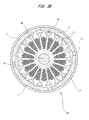
FIG. 2B is a view of a state in which an armature is removed from a yoke in a sectional view of the yoke along a line A-A inFIG. 2A ; -
FIG. 3A is a fragmentary sectional and development view of the wiper motor shown inFIG. 1 ; -
FIG. 3B is a perspective view of a gear housing cover; -
FIG. 3C is a development view of windings of an armature; -
FIG. 4A is a view of a state in which a motor unit is removed from the wiper motor; -
FIG. 4B is a view of a state in which ; -
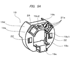
FIG. 5A is a perspective view of a brush holder part seen from a brush terminal connecting part side; -
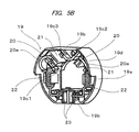
FIG. 5B is a perspective view of the brush holder part seen from a brush holder side; -
FIG. 6 is a view of the wiper motor according to the embodiment of the present invention seen from an output shaft side; -
FIG. 7 is a perspective view of a state in which a motor unit is removed from the wiper motor according to the embodiment of the present invention; -
FIG. 8 is a view of a state in which a control board is mounted on it shown inFIG. 2A ; and -
FIG. 9 is a sectional view of a speed reduction mechanism unit of the motor with speed reduction mechanism shown inFIG. 1 . - A
wiper motor 1 as a motor with speed reduction mechanism according to the present invention includes: as shown inFIGS. 1 and2A , amotor unit 10 for performing a rotating operation with electric current; and a speedreduction mechanism unit 25 for reducing the speed of rotation of themotor unit 10 and transmitting the speed reduced rotation to anoutput shaft 24. - As shown in
FIGS. 1 ,2A , and2B , themotor unit 10 includes a yoke (first case) 13 which is formed into a bottomed cylindrical shape, at least fourmagnets 11 are fixed to an inner circumferential surface thereof, agear housing 26 is fixed to one end surface thereof, and ashaft bearing part 12 is fixed to the other end surface thereof. - Furthermore, as shown in
FIGS. 2A and3A , themotor unit 10 includes anarmature shaft 14 having one end rotatably supported by thebearing part 12 and having aworm part 14a formed at its tip, acommutator 15 fixed to thearmature shaft 14, anarmature core 16 adjacent to thecommutator 15 and fixed to thearmature shaft 14, and awinging wire part 17 wound around thearmature core 16, wherein anarmature 18 is rotatably disposed on the inner side of the plurality ofmagnets 11. Furthermore, as shown inFIGS. 5A and5B , themotor unit 10 has abrush holder unit 19 including a plurality ofbrushes commutator 15 with the rotation of thearmature 18, andbrush holders respective brushes - The speed
reduction mechanism unit 25 includes aworm wheel part 25a for reducing the speed of rotation of themotor unit 10, and the gear housing (second case) 26 having a bottomed speed reduction mechanism accommodatingpart 26f in which theworm wheel part 25a is accommodated. Furthermore, the speedreduction mechanism unit 25 further includes agear housing cover 29 covering an opening of the speed reduction mechanism accommodatingpart 26f, and a brushholder accommodating part 26d in which thebrush holder unit 19 is accommodated. Theworm wheel part 25a includes theoutput shaft 24 for reducing the speed of rotation of thearmature 18 of themotor unit 10 and transmitting the speed reduced rotation, and the brushholder accommodating part 26d is cylindrically formed and is integrally molded with thegear housing 26. Thegear housing 26 and the gear housing cover (third case) 29 are fixed to each other by a plurality ofscrews 40. The wiper motor having an integrated case is constructed by mechanically connecting the yoke (first case) 13, the gear housing (second case) 26, and the gear housing cover (third case) 29 to each other. - The
worm wheel part 25a included in the speedreduction mechanism unit 25 is made of resin such as polyacetal, into a disk shape, and has an outer peripheral surface formed with anengaging part 25b engaged with theworm part 14a of thearmature shaft 14. Theoutput shaft 24 is integrally mounted at the center of rotation of theworm wheel part 25a. With this, when thearmature 18 rotates, with the rotation of theworm part 14a, theworm wheel part 25a engaged with theworm part 14a rotates with the reduced speed of rotation, thereby reducing the speed of rotation of thearmature 18 and transmitting the reduced speed of rotation to theoutput shaft 24. - To a base end of the
output shaft 24 of theworm wheel part 25a, a cylindrical (button-shaped)magnet 25c is attached so that its rotation center is axially aligned with the rotation center of theoutput shaft 24. Furthermore, themagnet 25c is polarized so as to have: an N pole in a range of 180 degrees in one circumferential direction defined around its rotation center as a center; and an S pole in a range of 180 degrees in the other circumferential direction. In the vicinity of theannular magnet 25c, a Hall IC forabsolute position detection 29d is provided on acontrol board 29c which will be further described below. - As shown in
FIG. 9 , the Hall IC forabsolute position detection 29d is configured to detect the change of magnetic field generated by themagnet 25c with the rotation of theoutput shaft 24, and to convert it into angle data. And on the basis of a signal generated by the Hall IC forabsolute position detection 29d so as to correspond to the change of magnetic field generated by themagnet 25c, an angle of a current position of a wiper arm on a windshield (not shown) from its specific position such as lower reversing position or stop position of the wiper device attached to the top of theoutput shaft 24 of the motor with speed reduction mechanism is calculated. Themagnet 25c is integrally fixed to the base end of the output shaft, a swingingmember 43 such as wiper arm or motor crank is directly fixed to one end of the output shaft by a fixingmember 44 such as nut so as not to move around it, and an intermediate portion of theoutput shaft 24 is supported by an outputshaft support part 26g formed as part of the gear housing 26 (second case) so as to extend in an axial direction. - Since the
output shaft 24 is prevented from being moved in the axial direction by this part, the movement of the wiper arm or the motor crank can be detected with accuracy by the Hall IC forabsolute position detection 29d. Also, since thewiper motor 1 is made up of a four-pole wiper motor, thewiper motor 1 can be reduced in size, and inertia of thewiper motor 1 can be reduced. Therefore, since the loss of thewiper motor 1, such as balance in rotation of thearmature 18, is reduced, and responsiveness of control and accuracy of wiping control can be enhanced. Furthermore, since it is not necessary to provide, to thewiper motor 1, a magnet for detecting the rotation of thearmature shaft 14 and a sensor for detecting the pole of the magnet, thearmature shaft 14 can be reduced in length, and thewiper motor 1 can be reduced in size. - Then, a heat dissipating structure of the
gear housing 26 will be described as features of the present invention on the basis ofFIGS. 2A ,3A ,6 and7 . - The
yoke 13 is integrally molded by press working from a plate material into a bottomed cylindrical shape, and amagnet fixing part 13a in which the plurality ofmagnets 11 are fixed onto its inner peripheral surface and ayoke connecting part 13d integrally connected to themagnet fixing part 13a are formed in theyoke 13. And in theyoke connecting part 13d, pairedcurved parts 13b and pairedflat surface parts 13c alternately connected so as to be formed into an elliptical shape seen from an axial direction. On the end face of theyoke 13, a flange shaped fixingpart 13e is formed, and thegear housing 26, which will be described further below, is fixed to the flange shaped fixingpart 13e. Theyoke connecting part 13d is formed so that an arc diameter is gradually widened from themagnet fixing part 13a toward the yoke end face. On the inner peripheral surface of themagnet fixing part 13a, fourmagnets 11 are fixed with an adhesive or the like so that two N poles and two S poles, which are different magnetic poles, are alternately disposed, that is, the same poles face each other. - The
armature shaft 14 has one end rotatably supported by the bearingpart 12 of theyoke 13, and thearmature shaft 14 is disposed on the inner side of the fourmagnets 11. Thearmature shaft 14 has the other end formed with theworm part 14a formed into a spiral shape by component rolling. - As shown in
FIG. 3A andFIG. 4A , thecommutator 15 includes an insulatingcylindrical part 15a formed into a cylindrical shape and made of insulating material such as thermosetting resin, and a plurality ofsegment parts 15b spaced at predetermined intervals in a circumferential direction on an outer peripheral surface of the insulatingcylindrical part 15a and made of electrical conducting material such as copper. Thecommutator 15 is fixed to thearmature shaft 14 so that the inner peripheral surface of the insulatingcylindrical part 15a is engaged with the outer peripheral surface of thearmature shaft 14. At one end on the outer peripheral surface of eachsegment part 15b, acoil connecting part 15c is formed, and eachcoil connecting part 15c is connected to acoil 17a. - The
armature core 16 is formed into a cylindrical shape by stacking in layers predetermined numbers of core substrates which are stamped out by press working, and thearmature core 16 includes a shaft fixing part to which thearmature shaft 14 is fixed, and eighteen teeth parts radially extending from the shaft fixing part. - As shown in
FIGS. 3A and3C , acoil 17a made of copper wire is wound around thearmature core 16. One end of thecoil 17a is fixed to thecoil connecting part 15c of one of thesegment parts 15b, and thecoil 17a is wound by lap winding between predetermined teeth parts a plurality of times. Furthermore, after thecoil 17a is wound by lap winding between the predetermined teeth parts the plurality of times, the other end of thecoil 17a is fixed to thecoil connecting part 15c of anothersegment part 15b. Then, a connecting line (electric current supply line) 17b is connected to onesegment part 15b facing anothersegment part 15b. In this manner, thecoil 17a is wound around thearmature core 16 by repeating a process of winding thecoil 17a about each teeth part. With this, when electric power is supplied to thebrushes coil 17a, and thearmature 18 is rotated, thereby driving thewiper motor 1. - When the four pole magnet is used, four brushes are normally required. However, in this invention, by connecting facing segments to each other through the connecting line (electric current supply line) 17b, the electric current flowing through a segment part from one
brush 20 flows also through a facing segment part via the connectingline 17b. With this, the number of brushes can be decreased from four to two. - As shown in
FIGS. 5A and5B , thebrush holder unit 19 includes abase part 19c in which pairedcurved parts 19a and pairedflat surface parts 19b are alternately connected so as to be formed into an elliptical shape. - The
base part 19c is formed with an opening portion 19c1 through which thearmature shaft 14 is penetrated, and a fixing opening portion 19c2 through which ascrew 41 is penetrated, thereby fixing thebrush holder unit 19 and thegear housing 26. And thebrush holders base part 19c, and twobrushes brush holders commutator 15. As shown inFIGS. 4A and5B , in this invention, twobrushes armature 18 at intervals of approximately 90 degrees. - The
brush holders 21 are disposed in the vicinity of one of the pairedflat surface parts 19b of thebase part 19c. Fixingclaws 21a of thebrush holders 21 are inserted in a brush holder fixing part 19c3 formed in thebase part 19c, and the fixingclaws 21a are folded on the back surface side of thebase part 19c, so that thebrush holder 21 is fixed to thebase part 19c. - Furthermore, the
brush holder unit 19 includes a brushholder guide wall 19d and a brushterminal connecting part 19e, and the brushholder guide wall 19d is formed into a shape approximately the same as the outer shape (elliptical shape) of thebase part 19c and disposed so as to extend at the right angle from thebase part 19c. And the brushterminal connecting part 19e protrudes from thebase part 19c in a direction opposite to the brushholder guide wall 19d and at the right angle with respect to thebase part 19c. Furthermore, the brushterminal connecting part 19e is disposed at a position facing thebrushes 20, that is, on the otherflat surface part 19b away from the oneflat surface part 19b where thebrushes brushes 20 to the brushterminal connecting part 19e and thecontrol board 29c electrically connected to the brushterminal connecting part 19e. - On the
base part 19c, choke coils 22, 22 as noise preventive elements are mounted, and one end of each of the choke coils 22, 22, and a corresponding one of thebrushes pigtails choke coil 22, a femaletype brush terminal 23 is electrically connected, and the femaletype brush terminal 23 is electrically connected to amale type terminal 29g provided to thegear housing cover 29. The femaletype brush terminal 23 has a tip thereof accommodated in the brushterminal connecting part 19e, and is exposed from the brushterminal connecting part 19e so as to be able to electrically connect to themale type terminal 29g of thegear housing cover 29. When thebrush holder unit 19 is mounted on the brushholder accommodating part 26d, the brushholder guide wall 19d abuts on an inner wall 26d1 of the brushholder accommodating part 26d, and thebrush holder unit 19 is guided to a bottom portion 26d2 of the brushholder accommodating part 26d. Then, thebrush holder unit 19 and thegear housing 26 are fixed with thescrew 41 penetrating through the fixing opening portion 19c2 formed in thebase part 19c. - As shown in
FIGS. 2A ,3A , and4B , thegear housing 26 is formed by die cast molding by using metal material such as aluminum. And thegear housing 26 is formed with ayoke fixing part 26a, and theyoke fixing part 26a and the flange shaped fixingpart 13e of theyoke 13 abut on each other, and theyoke 13 is mounted on thegear housing 26 with a plurality ofscrews 42. - The
yoke fixing part 26a is formed into an elliptical shape with pairedcurved parts 26b and pairedflat surface parts 26c being alternately connected so as to match the shape of the flange shaped fixingpart 13e. In thegear housing 26, the brushholder accommodating part 26d is integrally formed with theyoke fixing part 26a, and thebrush holder unit 19 is accommodated in the brushholder accommodating part 26d. On the bottom portion 26d2 of the brushholder accommodating part 26d, brushholder abutting parts 26e each abutting on the fixingclaw 21a of thebrush holder 21 are formed so as to protrude from the bottom portion 26d2. Heat generated from thebrushes claws 21a of thebrush holders 21 via the brushholder abutting parts 26e to thegear housing 26, and is dissipated from thegear housing 26 to the outside. - Furthermore, in the
gear housing 26, the speed reduction mechanismaccommodating part 26f in which theworm wheel part 25a is accommodated is formed so as to be adjacent to the brushholder accommodating part 26d. In thegear housing 26, the outputshaft supporting part 26g for directly or indirectly supporting theoutput shaft 24 is formed in a direction opposite to an opening of the speed reduction mechanismaccommodating part 26f. - Furthermore, in the speed reduction mechanism
accommodating part 26f, acover connecting part 26h opens. After thebrush holder unit 19 described above is accommodated in the brushholder accommodating part 26d, twomale type terminals 29g which are provided so as to protrude from the bottom surface of thegear housing cover 29 toward the speed reduction mechanismaccommodating part 26f penetrate through thecover connecting part 26h to be electrically connected to the femaletype brush terminals 23 of thebrush holder unit 19 disposed in the speed reduction mechanismaccommodating part 26f. - The
output shaft 24 protruding from the outputshaft supporting part 26g is fixed by an output shaft fixing part (a teeth washer) 27, and to the tip of theoutput shaft 24, a wiperdevice fixing part 24a to which a swingingmember 43 such as wiper arm or motor crank is directly or indirectly fixed by a fixingmember 44 such as nut is formed, thereby mechanically connecting components forming the wiper device (not shown). - As shown in
FIGS. 6 and7 ,first heat sinks 26i as first heat dissipating members for dissipating Joule heat generated by electrical factor, that is, contact resistance between thebrushes commutator 15, and frictional heat generated by mechanical factor, that is, sliding movement between thebrushes commutator 15, asecond heat sink 26j as a second heat dissipating member for dissipating heat generated fromFETs 29e mounted on the control board, which will be further described below, and athird heat sink 26k as a third heat dissipating member are formed on an outer peripheral surface of thegear housing 26 positioned at a back surface of the speed reduction mechanismaccommodating part 26f. - The
brushes flat surface parts 26c of the brushholder accommodating part 26d, and thefirst heat sinks 26i protrude from this surface, and are spaced from each other at predetermined intervals in parallel. Thefirst heat sinks 26i are formed so as to be parallel to a longitudinal direction of thearmature shaft 14. - As shown in
FIG. 7 , in this invention, since twobrushes first heat sinks 26i, heat generated from thebrushes first heat sinks 26i and dissipated to the outside. And, since thebrushes control board 29c with respect to thefirst heat sinks 26i, it is easy to transmit heat generated from the brushes to thefirst heat sinks 26i, and it is hard to transmit it to thecontrol board 29c. - Furthermore, as shown in
FIG. 5A , between thebase part 19c and the brushholder abutting part 26e of thegear housing 26, a gel typeheat conducting member 28 is disposed. Heat generated from thebrushes heat conducting member 28 to thefirst heat sinks 26i. - To an opening of the
gear housing 26, thegear housing cover 29 formed into a bottomed shape and formed of insulating material is provided. An open end face of thegear housing 26 and thegear housing cover 29 abut on each other, and thegear housing cover 29 is fixed to thegear housing 26 with the plurality ofscrews 40. - As shown in
FIGS. 3A ,3B , and4A , thegear housing cover 29 includes acoupler part 29a, and thecoupler part 29a is provided with a plurality ofterminals 29f. One end of each of the plurality ofterminals 29f is electrically connected to a connector part (not shown) provided to a vehicle, and the other end of each of the plurality ofterminals 29f is electrically connected to thecontrol board 29c. And theterminals 29f have intermediate portions thereof which are buried in thegear housing cover 29. - Furthermore, from a
bottom portion 29h of thegear housing cover 29, twomale type terminals 29g protrude, and are electrically connected to the femaletype brush terminals 23 disposed in thebrush holder unit 19. With this configuration, electric power supplied from a power supply of the vehicle is supplied to themotor unit 10 through the plurality ofterminals 29f, thecontrol board 29c, themale type terminals 29g, the femaletype brush terminals 23, thepigtails 20a, and thebrushes - As shown in
FIG. 8 , thecontrol board 29c is mounted on thebottom portion 29h of thegear housing cover 29 with a plurality of screws, and is accommodated in the speed reduction mechanismaccommodating part 26f of thegear housing 26. - On a surface of the
control board 29c facing thebottom portion 29h of the gear housing cover, the Hall IC forabsolute position detection 29d is provided. The Hall IC forabsolute position detection 29d is disposed so as to face themagnet 25c provided to the base end of the output shaft of theworm wheel part 25a, and configured to detect the rotating state of theoutput shaft 24 of thewiper motor 1. - And, based on the rotating state of the
output shaft 24 of thewiper motor 1, thecontrol board 29c is configured to control the rotation of thearmature 18 of themotor unit 10. - The
control board 29c is provided with the plurality ofFETs 29e to control electric current flowing through themotor unit 10 with an ON/OFF operation of theFETs 29e, and to control the rotation of thearmature 18 of themotor unit 10 in a forward direction and a reverse direction. Furthermore, on thecontrol board 29c, a temperature detecting part not shown in the drawing is disposed, thereby detecting the temperature of thecontrol board 29c. - When load is applied to the
wiper motor 1 and the temperature of thecontrol board 29c detected by the temperature detecting part becomes equal to or higher than a predetermined temperature, based on a signal from the temperature detecting part indicating that the temperature becomes equal to or higher than the predetermined temperature, thecontrol board 29c causes the rotation numbers to be decreased, and even further, causes the rotation of thearmature 18 to stop, thereby achieving protection of thecontrol board 29c of thewiper motor 1 by the temperature detecting part. - Also, on a surface near the FETs 29e of the speed reduction mechanism
accommodating part 26f, a FETheat dissipating part 26m is formed. The FETheat dissipating part 26m protrudes from the bottom surface of the speed reduction mechanismaccommodating part 26f toward an opening direction, and is formed near a back surface of thecontrol board 29c to which theFETs 29e are fixed. On the FETheat dissipating part 26m, a FETheat dissipating member 30 of a gel type and formed of a material with a high heat conductivity is mounted so as to fill a gap between thecontrol board 29c and the FETheat dissipating part 26m. Heat generated from theFETs 29e is transmitted via thecontrol board 29c and the FETheat dissipating member 30 to the FETheat dissipating part 26m, and is dissipated from thesecond heat sink 26j and thethird heat sink 26k, formed on the outer peripheral surface of thegear housing 26 to the outside of the gear housing. With this, an increase in temperature of thecontrol board 29c due to heating of theFETs 29e can be suppressed. For this reason, thewiper motor 1 can be actuated for a longer time. - Furthermore, between the
worm wheel part 25a accommodated in the speed reduction mechanismaccommodating part 26f and thecontrol board 29c, acontrol board cover 31 made of insulating material is mounted on thegear housing cover 29. Thecontrol board cover 31 is disposed between theworm wheel part 25a and thecontrol board 29c, and is fixed so that grease applied to the speedreduction mechanism unit 25 is not adhered to thecontrol board 29c. - When the wiper device is actuated for a long period of time, the
brushes motor unit 10, and theFETs 29e generate heat, thereby possibly preventing continuous actuation of the wiper device. For this reason, in the present invention, thesecond heat sink 26j and thethird heat sink 26k are further formed near thefirst heat sinks 26i on the outer peripheral surface of thegear housing 26 so as to extend outward (on a side opposite to the gear housing cover 29). The plurality ofFETs 29e are disposed near thesecond heat sink 26j and thethird heat sink 26k across thecontrol board 29c. With this, heat generated from theFETs 29e is dissipated via thecontrol board 29c from thesecond heat sink 26j and thethird heat sink 26k to the outside of thegear housing 26. - As described above, in the above embodiment, a case where the present invention is applied to a wiper motor having connecting lines has been described. However, the present invention is not meant to be restricted to this embodiment, and can be applied to a wiper motor in general, the motor having a brush accommodated in a gear housing formed into an elliptical shape, and a structure in which a heat sink is disposed on an outer peripheral surface of the gear housing in the vicinity of the brush.
- Furthermore, although the four-pole wiper motor provided with a four-pole magnet is described as one embodiment of the present invention, the wiper motor may be provided with a magnet larger in number of poles than the four-pole magnet, or a cylindrical magnet (ring magnet) polarized so as to have four or more poles.
- Furthermore, although the wiper motor having wiper component parts, such as armature and speed reduction mechanism, accommodated in the yoke and gear housing connected to the yoke are disclosed as one embodiment of the present invention, cases in which wiper component parts such as armature and speed reduction mechanism are accommodated may be formed of iron plate in advance, and after the wiper component parts are incorporated in one case, the other case may be mounted on it.
- The wiper motor is used as a driving source of a wiper device mounted on a vehicle such as an automobile, and used to wipe out rainwater and others attached onto a windshield by swing the wiper arm.
Claims (4)
- A wiper motor, comprising:a yoke;a magnet formed with at least four poles in which different magnetic poles are alternately disposed on an inner peripheral surface of the yoke;an armature including an armature shaft which has one end rotatably supported by a bottom portion of the yoke, a commutator which is fixed to the armature shaft, and a core which is fixed to the armature shaft and around which a winding wire is wound, wherein the armature is rotatably disposed on an inner side of the magnet;two brushes slidably contacting with the commutator, the brushes being disposed so as to be spaced apart from each other at intervals of 90 degrees;a speed reduction mechanism unit having an output shaft for transmitting the rotation of the armature shaft by meshing with a worm formed on the armature shaft;a gear housing connected to the yoke, the gear housing being formed with a speed reduction mechanism accommodating part having accommodated therein the speed reduction mechanism unit, and formed into a bottomed open shape;a gear housing cover covering an opening of the gear housing;a magnet attached to the output shaft;an absolute position detecting sensor disposed so as to face the magnet; anda control board having the absolute position detecting sensor attached thereto, the control board being disposed between the gear housing and the gear housing cover, and configured to control the rotation of the armature shaft.
- The wiper motor according to claim 1, wherein the output shaft is formed with a fixing part to which a swinging member is directly or indirectly fixed.
- A wiper motor, comprising:a case;a magnet formed with at least four poles in which different magnetic poles are alternately disposed on an inner peripheral surface of the case;an armature including an armature shaft which is rotatably supported by the case, a commutator which is fixed to the armature shaft, and a core which is fixed to the armature shaft and around which a winding wire is wound, wherein the armature is rotatably disposed on an inner side of the magnet;two brushes slidably contacting with the commutator, the brushes being disposed so as to be spaced apart from each other at intervals of 90 degrees;a speed reduction mechanism unit accommodated in the case, the speed reduction mechanism unit having an output shaft meshing with a worm formed on the armature shaft to transmit the rotation of the armature shaft;a magnet attached to the output shaft;an absolute position detecting sensor disposed so as to face the magnet; anda control board having the absolute position detecting sensor attached thereto, the control board being accommodated in the case, and configured to control the rotation of the armature shaft.
- The wiper motor according to claim 3, wherein the output shaft is formed with a fixing part to which a swinging member is directly or indirectly fixed.
Applications Claiming Priority (1)
| Application Number | Priority Date | Filing Date | Title |
|---|---|---|---|
| PCT/JP2011/076927 WO2013076815A1 (en) | 2011-11-22 | 2011-11-22 | Wiper motor |
Publications (2)
| Publication Number | Publication Date |
|---|---|
| EP2784912A1 true EP2784912A1 (en) | 2014-10-01 |
| EP2784912A4 EP2784912A4 (en) | 2015-08-12 |
Family
ID=48469295
Family Applications (1)
| Application Number | Title | Priority Date | Filing Date |
|---|---|---|---|
| EP11876134.5A Withdrawn EP2784912A4 (en) | 2011-11-22 | 2011-11-22 | Wiper motor |
Country Status (4)
| Country | Link |
|---|---|
| US (1) | US9525322B2 (en) |
| EP (1) | EP2784912A4 (en) |
| CN (3) | CN103947087B (en) |
| WO (1) | WO2013076815A1 (en) |
Families Citing this family (15)
| Publication number | Priority date | Publication date | Assignee | Title |
|---|---|---|---|---|
| RU2510561C2 (en) | 2009-07-30 | 2014-03-27 | Мицуба Корпорейшн | Gearmotor |
| US10320265B2 (en) * | 2009-07-30 | 2019-06-11 | Mitsuba Corporation | Wiper motor |
| JP6026972B2 (en) * | 2013-08-07 | 2016-11-16 | アスモ株式会社 | Reducer motor |
| CN103683679A (en) * | 2013-08-09 | 2014-03-26 | 张岳峰 | An electronic-type contactless unidirectionally-rotating intelligent windscreen wiper electric motor |
| CN103633768A (en) * | 2013-11-27 | 2014-03-12 | 镇江先锋汽车零部件有限公司 | Shell of wiper motor |
| JP6398815B2 (en) * | 2015-03-17 | 2018-10-03 | 株式会社デンソー | Reducer motor |
| DE102015220900A1 (en) * | 2015-10-27 | 2017-04-27 | Robert Bosch Gmbh | Wiper direct drive |
| EP3279043B1 (en) * | 2016-08-05 | 2018-12-05 | MEAS France | Sensor mounting system |
| DE102016221052A1 (en) * | 2016-10-26 | 2018-04-26 | Robert Bosch Gmbh | Wiper drive for a wiper system of a motor vehicle |
| US10864894B2 (en) * | 2017-01-20 | 2020-12-15 | Denso Corporation | Wiper device |
| ES2894253T3 (en) * | 2017-05-24 | 2022-02-14 | Ims Gear Se & Co Kgaa | Motor-gear connection arrangement, in particular for use in vehicles |
| CN107565733A (en) * | 2017-09-12 | 2018-01-09 | 天津富民伟业科技有限公司 | Wiper motor mounting reinforcement shell |
| JP7057083B2 (en) * | 2017-09-13 | 2022-04-19 | ミネベアミツミ株式会社 | Rotating device |
| US11722036B2 (en) | 2021-06-14 | 2023-08-08 | Commercial Vehicle Group, Inc. | Wiper motors and methods of manufacture and use thereof |
| JP7810004B2 (en) * | 2022-02-18 | 2026-02-03 | 株式会社デンソー | Electric Actuator |
Family Cites Families (12)
| Publication number | Priority date | Publication date | Assignee | Title |
|---|---|---|---|---|
| US5694812A (en) * | 1995-04-28 | 1997-12-09 | United Technologies Automotive, Inc. | Multi-functional apparatus employing an electromagnetic device and an intermittent motion mechanism |
| JP2001069722A (en) | 1999-08-31 | 2001-03-16 | Jidosha Denki Kogyo Co Ltd | Motor with rotation detection sensor for switchgear |
| JP4592435B2 (en) * | 2005-02-01 | 2010-12-01 | 日本電産サンキョー株式会社 | Small motor with encoder |
| JP2006220529A (en) * | 2005-02-10 | 2006-08-24 | Matsushita Electric Ind Co Ltd | Absolute rotation angle and torque detector |
| DE102005040647A1 (en) * | 2005-08-27 | 2007-03-08 | Valeo Systèmes d`Essuyage | Electromotive auxiliary drive e.g. windshield wiper drive, for e.g. road vehicle, has permanent magnet provided at shaft extension or at gearing unit, and magnetic sensors provided within bearing arrangement toward shaft axis |
| CN200969563Y (en) * | 2006-10-18 | 2007-10-31 | 北京交通大学 | Magnetic suspension rotary device |
| US8283915B2 (en) | 2007-03-07 | 2012-10-09 | Asmo Co., Ltd. | Sensor magnet device, gear mechanism and speed reducing electric motor |
| CN201118416Y (en) * | 2007-08-24 | 2008-09-17 | 宁波骏腾国际工贸有限公司 | FM DC drive electromotor device for washer |
| JP5022932B2 (en) | 2008-02-04 | 2012-09-12 | 株式会社ミツバ | Electric motor |
| JP4997152B2 (en) | 2008-03-14 | 2012-08-08 | 株式会社ミツバ | Electric motor and method for manufacturing the same |
| JP2010136588A (en) | 2008-12-08 | 2010-06-17 | Mitsuba Corp | Actuator |
| RU2510561C2 (en) | 2009-07-30 | 2014-03-27 | Мицуба Корпорейшн | Gearmotor |
-
2011
- 2011-11-22 CN CN201180075001.7A patent/CN103947087B/en active Active
- 2011-11-22 EP EP11876134.5A patent/EP2784912A4/en not_active Withdrawn
- 2011-11-22 WO PCT/JP2011/076927 patent/WO2013076815A1/en not_active Ceased
- 2011-11-22 CN CN201710669849.1A patent/CN107528417A/en active Pending
- 2011-11-22 US US14/357,816 patent/US9525322B2/en active Active
- 2011-11-22 CN CN201710669833.0A patent/CN107317429A/en active Pending
Also Published As
| Publication number | Publication date |
|---|---|
| CN107528417A (en) | 2017-12-29 |
| CN107317429A (en) | 2017-11-03 |
| CN103947087A (en) | 2014-07-23 |
| EP2784912A4 (en) | 2015-08-12 |
| WO2013076815A1 (en) | 2013-05-30 |
| US20150180305A1 (en) | 2015-06-25 |
| US9525322B2 (en) | 2016-12-20 |
| CN103947087B (en) | 2017-08-25 |
Similar Documents
| Publication | Publication Date | Title |
|---|---|---|
| EP2461464B1 (en) | Motor with speed reduction mechanism | |
| US9525322B2 (en) | Wiper motor | |
| US10320265B2 (en) | Wiper motor | |
| US6734589B2 (en) | Electric motor | |
| CN108141104B (en) | Direct drive for a windscreen wiper | |
| JP6095510B2 (en) | Wiper motor | |
| US6097122A (en) | Drive unit electric motor | |
| JP4159797B2 (en) | Electric motor | |
| CN202364062U (en) | wiper motor | |
| JPWO2013076815A1 (en) | Wiper motor |
Legal Events
| Date | Code | Title | Description |
|---|---|---|---|
| PUAI | Public reference made under article 153(3) epc to a published international application that has entered the european phase |
Free format text: ORIGINAL CODE: 0009012 |
|
| 17P | Request for examination filed |
Effective date: 20140514 |
|
| AK | Designated contracting states |
Kind code of ref document: A1 Designated state(s): AL AT BE BG CH CY CZ DE DK EE ES FI FR GB GR HR HU IE IS IT LI LT LU LV MC MK MT NL NO PL PT RO RS SE SI SK SM TR |
|
| DAX | Request for extension of the european patent (deleted) | ||
| RA4 | Supplementary search report drawn up and despatched (corrected) |
Effective date: 20150710 |
|
| RIC1 | Information provided on ipc code assigned before grant |
Ipc: H02K 5/04 20060101AFI20150706BHEP Ipc: H02K 7/06 20060101ALI20150706BHEP |
|
| STAA | Information on the status of an ep patent application or granted ep patent |
Free format text: STATUS: EXAMINATION IS IN PROGRESS |
|
| 17Q | First examination report despatched |
Effective date: 20170424 |
|
| STAA | Information on the status of an ep patent application or granted ep patent |
Free format text: STATUS: THE APPLICATION IS DEEMED TO BE WITHDRAWN |
|
| 18D | Application deemed to be withdrawn |
Effective date: 20190717 |