EP2784877A1 - Crimp terminal, crimp body, and method for manufacturing crimp body - Google Patents
Crimp terminal, crimp body, and method for manufacturing crimp body Download PDFInfo
- Publication number
- EP2784877A1 EP2784877A1 EP14161881.9A EP14161881A EP2784877A1 EP 2784877 A1 EP2784877 A1 EP 2784877A1 EP 14161881 A EP14161881 A EP 14161881A EP 2784877 A1 EP2784877 A1 EP 2784877A1
- Authority
- EP
- European Patent Office
- Prior art keywords
- distal end
- core wires
- end portion
- bottom portion
- side portion
- Prior art date
- Legal status (The legal status is an assumption and is not a legal conclusion. Google has not performed a legal analysis and makes no representation as to the accuracy of the status listed.)
- Granted
Links
Images





Classifications
-
- H—ELECTRICITY
- H01—ELECTRIC ELEMENTS
- H01R—ELECTRICALLY-CONDUCTIVE CONNECTIONS; STRUCTURAL ASSOCIATIONS OF A PLURALITY OF MUTUALLY-INSULATED ELECTRICAL CONNECTING ELEMENTS; COUPLING DEVICES; CURRENT COLLECTORS
- H01R4/00—Electrically-conductive connections between two or more conductive members in direct contact, i.e. touching one another; Means for effecting or maintaining such contact; Electrically-conductive connections having two or more spaced connecting locations for conductors and using contact members penetrating insulation
- H01R4/10—Electrically-conductive connections between two or more conductive members in direct contact, i.e. touching one another; Means for effecting or maintaining such contact; Electrically-conductive connections having two or more spaced connecting locations for conductors and using contact members penetrating insulation effected solely by twisting, wrapping, bending, crimping, or other permanent deformation
- H01R4/18—Electrically-conductive connections between two or more conductive members in direct contact, i.e. touching one another; Means for effecting or maintaining such contact; Electrically-conductive connections having two or more spaced connecting locations for conductors and using contact members penetrating insulation effected solely by twisting, wrapping, bending, crimping, or other permanent deformation by crimping
-
- G—PHYSICS
- G01—MEASURING; TESTING
- G01N—INVESTIGATING OR ANALYSING MATERIALS BY DETERMINING THEIR CHEMICAL OR PHYSICAL PROPERTIES
- G01N27/00—Investigating or analysing materials by the use of electric, electrochemical, or magnetic means
- G01N27/26—Investigating or analysing materials by the use of electric, electrochemical, or magnetic means by investigating electrochemical variables; by using electrolysis or electrophoresis
- G01N27/403—Cells and electrode assemblies
- G01N27/406—Cells and probes with solid electrolytes
- G01N27/4062—Electrical connectors associated therewith
-
- H—ELECTRICITY
- H01—ELECTRIC ELEMENTS
- H01R—ELECTRICALLY-CONDUCTIVE CONNECTIONS; STRUCTURAL ASSOCIATIONS OF A PLURALITY OF MUTUALLY-INSULATED ELECTRICAL CONNECTING ELEMENTS; COUPLING DEVICES; CURRENT COLLECTORS
- H01R4/00—Electrically-conductive connections between two or more conductive members in direct contact, i.e. touching one another; Means for effecting or maintaining such contact; Electrically-conductive connections having two or more spaced connecting locations for conductors and using contact members penetrating insulation
- H01R4/10—Electrically-conductive connections between two or more conductive members in direct contact, i.e. touching one another; Means for effecting or maintaining such contact; Electrically-conductive connections having two or more spaced connecting locations for conductors and using contact members penetrating insulation effected solely by twisting, wrapping, bending, crimping, or other permanent deformation
- H01R4/18—Electrically-conductive connections between two or more conductive members in direct contact, i.e. touching one another; Means for effecting or maintaining such contact; Electrically-conductive connections having two or more spaced connecting locations for conductors and using contact members penetrating insulation effected solely by twisting, wrapping, bending, crimping, or other permanent deformation by crimping
- H01R4/183—Electrically-conductive connections between two or more conductive members in direct contact, i.e. touching one another; Means for effecting or maintaining such contact; Electrically-conductive connections having two or more spaced connecting locations for conductors and using contact members penetrating insulation effected solely by twisting, wrapping, bending, crimping, or other permanent deformation by crimping for cylindrical elongated bodies, e.g. cables having circular cross-section
- H01R4/184—Electrically-conductive connections between two or more conductive members in direct contact, i.e. touching one another; Means for effecting or maintaining such contact; Electrically-conductive connections having two or more spaced connecting locations for conductors and using contact members penetrating insulation effected solely by twisting, wrapping, bending, crimping, or other permanent deformation by crimping for cylindrical elongated bodies, e.g. cables having circular cross-section comprising a U-shaped wire-receiving portion
-
- H—ELECTRICITY
- H01—ELECTRIC ELEMENTS
- H01R—ELECTRICALLY-CONDUCTIVE CONNECTIONS; STRUCTURAL ASSOCIATIONS OF A PLURALITY OF MUTUALLY-INSULATED ELECTRICAL CONNECTING ELEMENTS; COUPLING DEVICES; CURRENT COLLECTORS
- H01R43/00—Apparatus or processes specially adapted for manufacturing, assembling, maintaining, or repairing of line connectors or current collectors or for joining electric conductors
- H01R43/04—Apparatus or processes specially adapted for manufacturing, assembling, maintaining, or repairing of line connectors or current collectors or for joining electric conductors for forming connections by deformation, e.g. crimping tool
- H01R43/048—Crimping apparatus or processes
-
- H—ELECTRICITY
- H01—ELECTRIC ELEMENTS
- H01R—ELECTRICALLY-CONDUCTIVE CONNECTIONS; STRUCTURAL ASSOCIATIONS OF A PLURALITY OF MUTUALLY-INSULATED ELECTRICAL CONNECTING ELEMENTS; COUPLING DEVICES; CURRENT COLLECTORS
- H01R43/00—Apparatus or processes specially adapted for manufacturing, assembling, maintaining, or repairing of line connectors or current collectors or for joining electric conductors
- H01R43/04—Apparatus or processes specially adapted for manufacturing, assembling, maintaining, or repairing of line connectors or current collectors or for joining electric conductors for forming connections by deformation, e.g. crimping tool
- H01R43/048—Crimping apparatus or processes
- H01R43/0488—Crimping apparatus or processes with crimp height adjusting means
-
- H—ELECTRICITY
- H01—ELECTRIC ELEMENTS
- H01R—ELECTRICALLY-CONDUCTIVE CONNECTIONS; STRUCTURAL ASSOCIATIONS OF A PLURALITY OF MUTUALLY-INSULATED ELECTRICAL CONNECTING ELEMENTS; COUPLING DEVICES; CURRENT COLLECTORS
- H01R43/00—Apparatus or processes specially adapted for manufacturing, assembling, maintaining, or repairing of line connectors or current collectors or for joining electric conductors
- H01R43/16—Apparatus or processes specially adapted for manufacturing, assembling, maintaining, or repairing of line connectors or current collectors or for joining electric conductors for manufacturing contact members, e.g. by punching and by bending
-
- Y—GENERAL TAGGING OF NEW TECHNOLOGICAL DEVELOPMENTS; GENERAL TAGGING OF CROSS-SECTIONAL TECHNOLOGIES SPANNING OVER SEVERAL SECTIONS OF THE IPC; TECHNICAL SUBJECTS COVERED BY FORMER USPC CROSS-REFERENCE ART COLLECTIONS [XRACs] AND DIGESTS
- Y10—TECHNICAL SUBJECTS COVERED BY FORMER USPC
- Y10T—TECHNICAL SUBJECTS COVERED BY FORMER US CLASSIFICATION
- Y10T29/00—Metal working
- Y10T29/49—Method of mechanical manufacture
- Y10T29/49002—Electrical device making
- Y10T29/49117—Conductor or circuit manufacturing
- Y10T29/49174—Assembling terminal to elongated conductor
- Y10T29/49181—Assembling terminal to elongated conductor by deforming
- Y10T29/49185—Assembling terminal to elongated conductor by deforming of terminal
Definitions
- the present invention relates to a crimp terminal, a crimp body, and a method for manufacturing a crimp body.
- Patent Literature 1 describes a crimp terminal including a fixing portion having a bottom wall and a pair of side walls erected from both ends of the bottom wall, wherein both distal end parts of the side walls that are located on the side opposite to the bottom wall are bent toward the bottom wall, and wherein an enclosing portion surrounding core wires of a lead wire is formed by the bottom wall and both the side walls.
- Patent Literature 1 describes that when the relationship between the maximum width of the fixing portion, the maximum width of the enclosing portion, and the minimum thickness of the bottom wall and the relationship between the maximum height from the bottom wall to the starting point of the side wall farthest from the bottom wall and the maximum height from the starting point to the end of each distal end part satisfy predetermined conditions, the core wires of the lead wire can be fixed firmly.
- the lead wire When a crimp terminal cannot fix core wires of a lead wire firmly, for example, the lead wire may be prone to come off after crimping. In addition, insufficiency of the adhesion between the crimp terminal and the core wires and the adhesion between the core wires may cause variation in the contact resistance in the crimp terminal part. So, it has been desired to fix core wires of a lead wire more firmly.
- the present invention has been made to solve such a problem, and it is a main object of the present invention to fix core wires of a lead wire more firmly.
- a crimp terminal in the present invention comprises a holding portion including a bottom portion, a first side portion continuous with the bottom portion, and a second side portion continuous with the side of the bottom portion opposite to the first side portion, wherein the first side portion has a first distal end portion located at the end on the side opposite to the side continuous with the bottom portion, and the thickness of the first distal end portion is 70% or less of the thickness of the bottom portion, and wherein the second side portion has a second distal end portion located at the end on the side opposite to the side continuous with the bottom portion, and the thickness of the second distal end portion is 70% or less of the thickness of the bottom portion.
- the thickness of the first distal end portion of the first side portion is 70% or less of the thickness of the bottom portion
- the thickness of the second distal end portion of the second side portion is 70% or less of the thickness of the bottom portion.
- the holding portion of the crimp terminal can surround and crimp a plurality of core wires of a lead wire with the bottom portion, the first side portion, and the second side portion by curving the first side portion and the second side portion such that the first distal end portion and the second distal end portion face the bottom portion.
- the first distal end portion and the second distal end portion easily bite into the plurality of core wires since the thicknesses of the first distal end portion and the second distal end portion are 70% or less of the thickness of the bottom portion. Therefore, the core wires of the lead wire can be fixed more firmly with the bottom portion, the first side portion, and the second side portion. The smaller the thickness of the first distal end portion and the thickness of the second distal end portion, the more easily the first and second distal end portions bite into the plurality of core wires.
- the thickness of the first distal end portion and the thickness of the second distal end portion are preferably 40% or more of the thickness of the bottom portion.
- the thickness of the first distal end portion does not necessarily have to be 70% or less of the thickness of the bottom portion
- the thickness of the second distal end portion does not necessarily have to be 70% or less of the thickness of the bottom portion.
- the thicknesses of the first distal end portion and the second distal end portion may be smaller than the diameter of the core wires of the lead wire to be crimped.
- the first distal end portion and the second distal end portion bite into the plurality of core wires more easily.
- the thicknesses of the first distal end portion and the second distal end portion do not necessarily have to be smaller than the diameter of the core wires of the lead wire that are crimped.
- the first distal end portion and the second distal end portion may be formed by compression processing.
- the strength of the first and second distal end portions can be made high compared to the case where the first and second distal end portions are thinned, for example, by polishing or grinding.
- the thicknesses of the first and the second distal end portions after processing may be 70% or less of the thicknesses before processing.
- a crimp body in the present invention comprises a lead wire having a plurality of core wires; and a crimp terminal comprising a holding portion including a bottom portion, a curved first side portion continuous with the bottom portion, and a curved second side portion continuous with the side of the bottom portion opposite to the first side portion, the first side portion and the second side portion are curved such that a first distal end portion that is the distal end portion of the first side portion and a second distal end portion that is the distal end portion of the second side portion face the bottom portion, and the holding portion thereby surrounds and crimps the plurality of core wires with the bottom portion, the first side portion, and the second side portion, and when the holding portion is viewed in a section perpendicular to the axial direction of the core wires, in the section, horizontal direction is defined as the direction of a tangent to the curved part of the first side portion and the curved part of the second side portion, height direction is defined as the direction perpendicular to the horizontal direction,
- the holding portion is sufficiently compressed in the height direction since the crimp height CH is 1.20 ⁇ 0.05 mm and the crimp width CW is 1.66 ⁇ 0.05 mm in the section of the holding portion. Therefore, the core wires of the lead wire can be fixed more firmly.
- the first distal end portion and the second distal end portion may bite into the plurality of core wires.
- “the first side portion and the second side portion are curved such that a first distal end portion that is the distal end portion of the first side portion and a second distal end portion that is the distal end portion of the second side portion face the bottom portion” describes the direction of the curvature of the first side portion 72 and the second side portion 73. Therefore, the crimp bodies of the present invention also include a crimp body in which the first distal end portion and the second distal end portion do not face the bottom portion 74 in a state after crimping.
- a height Ha that is the distance in the height direction of the contact part between the first side portion and the second side portion may be 0.15 mm or more.
- the contact (crimping) between the first side portion and the second side portion is sufficient, and the core wires of the lead wire can be fixed more firmly.
- an angle ⁇ that is the angle between the contact part between the first side portion and the second side portion and the height direction may be 0° or more and 30° or less.
- the first side portion and the second side portion can crimp the core wires in a balanced manner, and the core wires of the lead wire can be fixed more firmly.
- a distance CFA that is the minimum distance in the height direction between the lowermost part of a surface of the bottom portion on the side of the core wires, and the first distal end portion side of the first side portion and the second distal end portion side of the second side portion may be 0.125 mm or more.
- the distance CFA is less than 0.125 mm, the distance between at least one of the first distal end portion side of the first side portion and the second distal end portion side of the second side portion and the bottom portion is small, and some of the core wires may be excessively crushed. This can be prevented by making the distance CFA 0.125 mm or more. That is, by making the distance CFA 0.125 mm or more, the plurality of core wires can be crimped in a balanced manner, and the core wires of the lead wire can be fixed more firmly.
- a distance CFE that is the distance in the height direction between the tangent in the horizontal direction to the first distal end portion side of the first side portion and the tangent in the horizontal direction to the second distal end portion side of the second side portion may be 0 mm or more and 0.25 mm or less.
- the first side portion and the second side portion can crimp the core wires in a balanced manner, and the core wires of the lead wire can be fixed more firmly. The smaller the value of the distance CFE, the more preferable.
- the compression rate CR [%] (the area of the region surrounded by the bottom portion, the first side portion, and the second side portion) / ⁇ (the cross-sectional area of each core wire before crimping) x (the number of the crimped core wires) ⁇ x 100
- the compression rate CR [%] may be 87% or less.
- the crimp terminal compresses the core wires sufficiently, and the core wires of the lead wire can be fixed more firmly.
- the lower the compression rate CR the more firmly the core wires can be fixed.
- the lower limit of the compression rate CR is determined by, for example, the material and number of the core wires and the force applied during crimping.
- the compression rate CR may be, for example, 50% or more.
- the crimp body of the present invention in the section, it is preferable that no cracks are generated in rising parts on the side of the core wires from the bottom portion to the first side portion and the second side portion. In this case, compared to the case where cracks are generated, the strength of the holding portion is high, and therefore the core wires of the lead wire can be fixed more firmly.
- a burr height Gh that is the height of a burr on the bottom portion may be 0 mm or more and 0.25 mm or less, and the burr may be within a region that is closer to the core wires than the lowermost part of the bottom portion in the height direction.
- a burr may be generated on the bottom portion. This burr contributes little to the fixing of the core wires. The larger the burr, the higher the percentage of part of the member forming the bottom portion and the first and second side portions that does not affect the fixing of the core wires, and therefore the more insufficient the fixing of the core wires.
- the burr height Gh is 0 mm or more and 0.25 mm or less, such an effect of the burr can be made relatively small.
- the fact that the burr height Gh is 0 mm means that no burr is generated.
- the burr heights Gh of the plurality of burrs be all 0 mm or more and 0.25 mm or less.
- a burr width Gb that is the width in the horizontal direction of a burr on the bottom portion may be 0 mm or more and 0.125 mm or less.
- the burr width Gb is 0 mm or more and 0.125 mm or less, the above-described effect of the burr can be made relatively small.
- the fact that the burr width Gb is 0 mm means that no burr is generated.
- the burr widths Gb of the plurality of burrs be all 0 mm or more and 0.125 mm or less.
- a bottom portion thickness Sb that is the thickness of the bottom portion may be 0.1875 mm or more.
- the strength of the bottom portion is higher, and therefore the core wires of the lead wire can be fixed more firmly.
- the crimp body of the present invention described above can be obtained relatively easily, for example, by crimping a plurality of core wires using the crimp terminal of the present invention described above.
- a method for manufacturing a crimp body includes a crimp terminal including a holding portion including a bottom portion, a first side portion continuous with the bottom portion, and a second side portion continuous with the side of the bottom portion opposite to the first side portion, wherein the first side portion has a first distal end portion located at the end on the side opposite to the side continuous with the bottom portion, and the thickness of the first distal end portion is 70% or less of the thickness of the bottom portion, and wherein the second side portion has a second distal end portion located at the end on the side opposite to the side continuous with the bottom portion, and the thickness of the second distal end portion is 70% or less of the thickness of the bottom portion, the method comprising the steps of:
- a crimp terminal in which, as with the crimp terminal of the present invention described above, the thickness of the first distal end portion is 70% or less of the thickness of the bottom portion and the thickness of the second distal end portion is 70% or less of the thickness of the bottom portion is prepared, and crimping of the plurality of core wires is performed using this. That is, in a state before crimping, the thickness of the first distal end portion of the first side portion is 70% or less of the thickness of the bottom portion, and the thickness of the second distal end portion of the second side portion is 70% or less of the thickness of the bottom portion.
- the first side portion and the second side portion are curved such that the first distal end portion and the second distal end portion face the bottom portion, and the plurality of core wires are surrounded and crimped with the bottom portion, the first side portion, and the second side portion. Therefore, the first distal end portion and the second distal end portion easily bite into the plurality of core wires, and the core wires of the lead wire can be fixed more firmly with the bottom portion, the first side portion, and the second side portion.
- the crimp terminal in which the thicknesses of the first distal end portion and the second distal end portion are smaller than the diameter of the core wires of the lead wire may be prepared.
- the first distal end portion and the second distal end portion bite into the plurality of core wires more easily.
- Fig. 1 is a longitudinal sectional view of a gas sensor 10 having a contact fitting 71 that is an embodiment of a crimp terminal of the present invention.
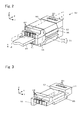
- Fig. 2 is a perspective view of a connector 50
- Fig. 3 is an exploded perspective view showing a housing 51 of the connector 50.
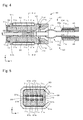
- Fig. 4 is a sectional view taken along line A-A of Fig. 2
- Fig. 5 is a sectional view taken along line B-B of Fig. 4
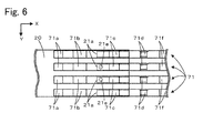
- Fig. 6 is an explanatory diagram showing the positional relationship between contact fittings 71 and a sensor element 20 as viewed from a first housing 51a side.
- the gas sensor 10 includes the sensor element 20 that measures a predetermined gas component in gas to be measured, a protective cover 30 that protects one end of the sensor element 20, and a sensor assembly 40 that includes the connector 50 electrically connected to the sensor element 20.
- the gas sensor 10 is attached, for example, to an exhaust gas pipe of a vehicle, and is used to measure gas components such as NOx and O 2 contained in exhaust gas as gas to be measured.
- the sensor element 20 is an elongated element having a plate-like shape, and is formed by laminating, for example, six ceramic substrates that are oxygen ion conductive solid electrolyte layers of zirconia (ZrO 2 ) or the like.
- the end of the sensor element 20 that is closest to the protective cover 30 will be referred to as distal end, and the end of the sensor element 20 that is closest to the connector 50 will be referred to as proximal end.
- the first surface electrodes 21a and the second surface electrodes 21b will be collectively referred to as electrodes 21.
- the electrodes 21 are for applying a voltage to the sensor element 20, and for taking out electromotive force or current generated according to the concentration of a gas component detected by the sensor element 20, and are electrically connected through electrical paths inside the sensor element 20 to electrodes (not shown) in the distal end of the sensor element 20.
- the positions of the first surface electrodes 21a and the second surface electrodes 21b will be described later.
- the protective cover 30 is disposed so as to surround the distal end of the sensor element 20 as shown in Fig. 1 .
- the protective cover 30 includes an inner protective cover 31 that covers the distal end of the sensor element 20, and an outer protective cover 32 that covers the inner protective cover 31.
- the inner protective cover 31 is formed in a cylindrical shape, and has an inner protective cover hole 31a for introducing gas to be measured to the distal end of the sensor element 20.
- the outer protective cover 32 is formed in a bottomed cylindrical shape, and has, in the side surface thereof, outer protective cover holes 32a for introducing gas to be measured.
- the inner protective cover 31 and the outer protective cover 32 are made of metal such as stainless steel.
- the sensor assembly 40 includes a main fitting 41 made of meal, an inner cylinder 42 and an outer cylinder 46 that are cylindrical and that are fixed to the main fitting 41 by welding, and the connector 50 connected to the proximal end of the sensor element 20.
- the main fitting 41 can be attached, for example, to an exhaust gas pipe of a vehicle with an external thread portion 41a.
- a plurality of ceramic supporters 43a to 43c, and ceramic powder 44a and 44b such as talc filling the space between the ceramic supporters 43a and 43b and the space between the ceramic supporters 43b and 43c are enclosed within the inner cylinder 42, and these are sealed between a metal ring 45 and the inner wall of the main fitting 41.
- the outer cylinder 46 covers the peripheries of the inner cylinder 42, the sensor element 20, and the connector 50, and lead wires 48 connected to the connector 50 are pulled out through an open end 46a to the outside.
- the lead wires 48 are electrically connected through the connector 50 to the electrodes 21 of the sensor element 20. Gaps between the outer cylinder 46 and the lead wires 48 are sealed by a rubber plug 47.
- the connector 50 includes the first housing 51a and a second housing 51b that are made of ceramic such as sintered alumina body, the contact fittings 71 that are held by the first housing 51a or the second housing 51b and that face and are in contact with the electrodes 21 of the sensor element 20 on a one-to-one basis, and a metal clamp 90 that clamps and fixes the first housing 51a and the second housing 51b.
- the first housing 51a and the second housing 51b are members that each hold four contact fittings 71 arranged in a direction (Y direction) perpendicular to the longitudinal direction of the contact fittings 71 (X direction).
- the first housing 51a and the second housing 51b have the same shape, so the same reference numerals will be used to designate the same components in the first housing 51a and the second housing 51b.
- the first housing 51a and the second housing 51b will be collectively referred to as housings 51.
- Each housing 51 includes four locking grooves 52 that lock the contact fittings 71, four insertion holes 53 into which the contact fittings 71 are inserted, and locking portions 54 (see Fig. 4 ) formed in the insertion holes 53 and locking the contact fittings 71.
- Each housing 51 has a protruding portion 55 on one side thereof in the Y direction, and restricting members 56 and 57 that restrict the distance in the Z direction between the first housing 51a and the second housing 51b on the other side thereof, with the sensor element 20 interposed therebetween (see Fig. 2 and Fig. 3 ).
- the protruding portion 55 is inserted into the recess between the restricting member 56 and the restricting member 57 of the opposite housing 51, and the relative positions of the first housing 51a and the second housing 51b in the X direction can thereby be fixed.
- the contact fittings 71 are metal members held by the housings 51 at positions facing the electrodes 21 of the sensor element 20 on a one-to-one basis, and each include, as shown in Fig. 4 , a distal end portion 71a that has a curved shape and that is thereby locked in the locking groove 52, a supporting portion 71b that is curved and protruded toward the sensor element 20, a conduction portion 71c that is curved and protruded toward the sensor element 20 and that is thereby in contact with the electrode 21, an upright portion 71d that is inserted into the insertion hole 53, a curved portion 71f that is pulled out to the outside of the connector 50, and a holding portion 71g that crimps and holds a plurality of core wires 48a of a lead wire 48 outside the connector 50.
- the holding portion 71g and the lead wire 48 crimped by the holding portion 71g will be collectively referred to as crimp body 80.
- the supporting portion 71b and the conduction portion 71c are arranged along the longitudinal direction of the contact fitting 71 (the X direction in Fig. 4 ), and the conduction portion 71c is disposed at a position closer to the holding portion 71g than the supporting portion 71b.
- the supporting portion 71b and the conduction portion 71c are both formed so as to be able to be elastically deformed, and both have a spring constant within a range, for example, of 500 to 4000 N/mm.
- the upright portion 71d has a hook portion 71e that has a curved shape and that is thereby locked to the locking portion 54.
- the conduction portions 71c of the contact fittings 71 held by the first housing 51a face and are in contact with the first surface electrodes 21a of the sensor element 20 on a one-to-one basis
- the conduction portions 71c of the contact fittings 71 held by the second housing 51b face and are in contact with the second surface electrodes 21b of the sensor element 20 on a one-to-one basis (see Fig. 4 and Fig. 5 ).
- the first surface electrodes 21a of the sensor element 20 extend from the proximal end of the sensor element 20 (the right end in Fig. 4 and Fig. 6 ) to a position between the conduction portions 71c and the supporting portions 71b.
- the central two first surface electrodes 21a are electrically connected to through holes 21e that are formed for electrical connection to the above-described electrical paths inside the sensor element 20.
- each through hole 21e is formed at a position between the conduction portion 71c and the supporting portion 71b.
- the positional relationship between the second surface electrodes 21b and the contact fittings 71, and the positions of through holes 21e electrically connected to the second surface electrodes 21b are the same as this, so the description thereof will be omitted.
- Fig. 7 is a sectional view taken along line C-C of Fig. 4 .
- Fig. 7 is a section perpendicular to the axial direction of the core wires 48a (the X direction in Fig. 4 ).
- Fig. 7A is an explanatory diagram showing the whole section of the holding portion 71g, and
- Fig. 7B is an enlarged view of the contact part between the first side portion 72 and the second side portion 73 in Fig. 7A (the part surrounded by the dashed circle). As shown in Fig.
- the holding portion 71g includes a bottom portion 74, a first side portion 72 that is continuous with the bottom portion 74 and that is erected from the bottom portion 74, and a second side portion 73 that is continuous with the bottom portion 74 and that is erected from the bottom portion 74.
- the first side portion 72 is continuous with the left side of the bottom portion 74 in Fig. 7
- the second side portion 73 is continuous with the side of the bottom portion 74 opposite to the first side portion 72 (the right side in Fig. 7 ).
- the first side portion 72 has a first distal end portion 72a located at the end on the side opposite to the side continuous with the bottom portion 74.
- the second side portion 73 has a second distal end portion 73a located at the end on the side opposite to the side continuous with the bottom portion 74.
- the first side portion 72 and the second side portion 73 are curved such that the first distal end portion 72a of the first side portion 72 and the second distal end portion 73a of the second side portion 73 face the bottom portion 74.
- a plurality of (19 in this embodiment) core wires are thereby surrounded and crimped with the bottom portion 74, the first side portion 72, and the second side portion 73.
- the holding portion 71g and the core wires 48 are electrically connected with each other, and form a crimp body 80 including the holding portion 71g and the lead wire 48.
- the part of the first side portion 72 on the side opposite to the bottom portion 74 and the part of the second side portion 73 on the side opposite to the bottom portion 74 are curved so as to approach each other.
- the first distal end portion 72a and the second distal end portion 73a bite into the plurality of core wires 48a of the lead wire 48.
- the first side portion 72 and the second side portion 73 are curved such that the first distal end portion 72a of the first side portion 72 and the second distal end portion 73a of the second side portion 73 'face the bottom portion 74'" describes the direction of curvature of the first side portion 72 and the second side portion 73, and the first distal end portion 72a and the second distal end portion 73a do not necessarily have to face the bottom portion 74 in the state after crimping.
- they may face in a direction different from the direction toward the bottom portion 74 (to the upper right in the figure).
- the holding portion 71g is formed so as to satisfy predetermined first to tenth conditions in the section shown in Fig. 7 .
- the first to tenth conditions will be described with reference to Fig. 7 below.
- horizontal direction and height direction in the section shown in Fig. 7 will be defined.
- horizontal direction is defined as the direction of a tangent Lt1 to the curved part of the first side portion 72 and the curved part of the second side portion 73 in the section shown in Fig. 7 .
- the tangent Lt1 to the curved part of the first side portion 72 and the curved part of the second side portion 73 is a line connecting the vertices of the curved parts of the first side portion 72 and the second side portion 73 on the side far from the bottom portion 74 (the upper side in Fig. 7 ) as shown in Fig. 7A .
- the side of the first side portion 72 will be referred to as leftward direction
- the side of the second side portion 73 will be referred to as rightward direction.
- Height direction is defined as the direction perpendicular to the horizontal direction.
- the side of the bottom portion 74 will be referred to as downward direction
- the side of the first side portion 72 and the second side portion 73 will be referred to as upward direction.
- the first condition is that "the crimp height CH is 1.20 ⁇ 0.05 mm, and the crimp width is 1.66 ⁇ 0.05 mm.”
- the crimp height CH is the height from the bottom surface of the bottom portion 74 to the tangent Lt (see Fig. 7A ).
- the crimp width CW is the width in the horizontal direction of the holding portion 71g (see Fig. 7A ).
- the second condition is that "the height Ha is 0.15 mm or more."
- the height Ha is the distance in the height direction of the contact part between the first side portion 72 and the second side portion 73 (see Fig. 7B ).
- points P1 and P2 are the ends of the contact part between the first side portion 72 and the second side portion 73. Therefore, the height Ha can be obtained as the distance in the height direction between the points P1 and P2.
- the height Ha although it is not particularly limited, may be, for example, 0.30 mm or less.
- the third condition is that "the angle ⁇ is 0° or more and 30° or less.”
- the angle ⁇ is the angle between the contact part between the first side portion 72 and the second side portion 73 and the height direction (see Fig. 7B ).
- the contact part between the first side portion 72 and the second side portion 73 is not limited to a straight line and can be a curved line. So, the angle ⁇ is defined as the angle between the straight line connecting the points P1 and P2 at both ends of the contact part and the height direction.
- the fourth condition is that "the distance CFA is 0.125 mm or more."
- the distance CFA is the minimum distance in the height direction between the lowermost part (the lowermost part in Fig. 7A ) of the surface of the bottom portion 74 on the side of the core wires (the upper surface of the bottom portion 74 in Fig. 7A ), and the first distal end portion 72a side of the first side portion 72 and the second distal end portion 73a side of the second side portion 73 (see Fig. 7A ).
- the distance CFA is the distance between the tangent Lt5 parallel to the horizontal direction to the lowermost part of the upper surface of the bottom portion 74, and one of the tangent Lt 2 in the horizontal direction to the first distal end portion 72a side of the first side portion 72 and the tangent Lt 3 in the horizontal direction to the second distal end portion 73a side of the second side portion 73 that is closer to the tangent Lt5.
- the second distal end portion 73a side of the second side portion 73 bites deeper than the first distal end portion 72a side of the first side portion 73.
- the distance CFA is the minimum distance in the height direction between the lowermost part of the upper surface of the bottom portion 74 and the second distal end portion 73a side of the second side portion 73 (the distance between the tangent Lt5 and the tangent Lt3).
- the second distal end portion 73a side of the second side portion 73 may be defined as "the part of the second side portion 73 that bites (is entangled) into the plurality of core wires 48a.”
- serrations to be described in detail later
- the distance CFA is obtained in the section of the part where serrations are not formed.
- the distance CFA is obtained in the section of the part where serrations are formed.
- the distance CFA although it is not particularly limited, may be, for example, 0.40 mm or less.
- the fifth condition is that "the distance CFE is 0 mm or more and 0.25 mm or less.”
- the distance CFE is the distance in the height direction between the tangent Lt 2 in the horizontal direction to the first distal end portion 72a side of the first side portion 72 and the tangent Lt 3 in the horizontal direction to the second distal end portion 73a side of the second side portion 73 (see Fig. 7A ).
- the tangent Lt2 is a tangent that is tangent to the lower end of the first distal end portion 72a side of the first side portion 72 as shown in Fig. 7A ).
- the tangent Lt3 is a tangent that is tangent to the lower end of the second distal end portion 73a side of the second side portion 73 as shown in Fig. 7A ).
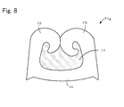
- the sixth condition is that "the compression rate CR [%] is 87% or less.”
- the compression rate CR [%] (the area of the region surrounded by the bottom portion 74, the first side portion 72, and the second side portion 73) / ⁇ (the cross-sectional area of each core wire 48a before crimping) x (the number of the crimped core wires 48a) ⁇ x 100.
- Fig. 8 is an explanatory diagram of the region 77 surrounded by the bottom portion 74, the first side portion 72, and the second side portion 73. Fig. 8 shows the same section as Fig. 7A . The area of the hatched region 77 shown in Fig.
- the lower limit of compression rate CR is determined by, for example, the material and number of the core wires 48a and the force applied during crimping.
- the compression rate CR may be, for example, 50% or more.
- the seventh condition is that "no cracks are generated in rising parts on the side of the core wires 48a from the bottom portion 74 to the first side portion 72 and the second side portion 73.”
- the rising part 74a is “the rising part on the side of the core wires 48a from the bottom portion 74 to the first side portion 72.”
- the rising part 74b is "the rising part on the side of the core wires 48a from the bottom portion 74 to the second side portion 73.”
- the eighth condition is that "the burr height Gh of the bottom portion 74 is 0 mm or more and 0.25 mm or less, and the burr is within a region that is closer to the core wires 48a than the lowermost part (the lowermost surface) of the bottom portion 74 in the height direction.”
- the fact that the burr height Gh is 0 mm means that no burr is generated.
- a burr 75 and a burr 76 may be generated at both ends of the bottom portion 74 as shown in Fig. 7A .
- the heights of the burr 75 and the burr 76 from the bottom portion 74 are referred to as burr heights Gh.
- the eighth condition is deemed to be satisfied when the burr heights Gh of the burrs are all within the above range.
- the burr is within a region that is closer to the core wires 48a than the lowermost part of the bottom portion 74 in the height direction
- the burrs 75 and 76 at both ends are within the region that is closer to the core wires 48a than the lowermost part of the bottom portion 74 in the height direction.”
- the ninth condition is that "the burr widths Gb of the bottom portion 74 are all 0 mm or more and 0.125 mm or less.”
- the burr widths Gb are the widths in the horizontal direction of the burrs 75 and 76 (see Fig. 7A ).
- the fact that the burr width Gb is 0 mm means that no burr is generated.
- the ninth condition is deemed to be satisfied when the burr widths Gb of the burrs are all within the above range.
- the bottom portion thickness Sb is 0.1875 mm or more.
- the bottom portion thickness Sb is the thickness in the height direction of the part of contact point P3 between the above tangent Lt4 and the bottom portion 74 (see Fig. 7A ).
- serrations to be described in detail later
- the bottom portion thickness Sb is obtained as the thickness in the section of the part where serrations are not formed.
- the bottom portion thickness Sb is obtained as the thickness in the section of the part where serrations are formed.
- the bottom portion thickness Sb although it is not particularly limited, may be, for example, 0.30 mm or less.
- the holding portion 71g of this embodiment satisfies all of the above-described first to tenth conditions in the section of Fig. 7 .
- the holding portion 71g can fix the core wires 48a of the lead wire 48 more firmly.
- the number of spaces between the core wires 48a be small. The smaller the number of spaces, the more hardly the core wires 48a are displaced, and the more firmly the core wires 48a can be fixed.
- the number of spaces is preferably one or less (up to one space is acceptable).
- the clamp 90 is made by bending a metal plate as shown in Fig. 2 and Fig. 5 , and has an elastic force capable of clamping the first housing 51a and the second housing 51b and pressing them toward each other.
- the restricting members 56 and 57 of the first housing 51a come into contact with the second housing 51b
- the restricting members 56 and 57 of the second housing 51b come into contact with the first housing 51a.
- the distance between the first housing 51a and the second housing 51b is thereby fixed.
- the clamp 90 clamps the first housing 51a and the second housing 51b with the sensor element 20 and the contact fittings 71 sandwiched between the first housing 51a and the second housing 51b such that the conduction portions 71c of the contact fittings 71 face the first surface electrodes 21a or the second surface electrodes 21b of the sensor element 20, the supporting portions 71b and the conduction portions 71c are elastically deformed by the pressing force from the clamp 90 and clamp and fix the sensor element 20.
- the supporting portions 71b and the conduction portions 71c are elastically deformed, the sensor element 20 can be reliably clamped and fixed by the resulting pressing force. Since the conduction portions 71c are elastically deformed, the electrical contact between the conduction portions 71c and the electrodes 21 can be maintained more reliably.
- a method for manufacturing the contact fitting 71 will be described.
- the contact fitting 71 is manufactured by punching and bending a metal plat.
- Fig. 9 is an explanatory diagram showing the state of the contact fitting 71 before bending.
- Fig. 10 is a perspective view of the contact fitting 71 after bending.
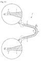
- Fig. 11 is a sectional view taken along line D-D of Fig. 10 .
- a metal plate is punched into a shape having a substantially rectangular metal plate portion 100, a metal piece 110 continuous with a long side of the metal plate portion 100, and substantially rectangular metal pieces 122 and 123 continuous with the long sides of a region 100g at one end of the metal plate portion 100.
- the metal piece 122 is located so as to be continuous with the side of the region 100g opposite to the metal piece 123.
- serrations 78 are formed in the surfaces of the region 100g and the metal pieces 122 and 123 on the near side of Fig. 9 . Although, in this embodiment, as shown, three serrations 78 are formed, the number of serrations 78 is not limited to this, and serrations 78 may not be formed.
- regions 100a and 100f of the metal plate portion 100 are curved toward the near side of Fig. 9 to form the distal end portion 71a and the curved portion 71f shown in Fig. 4 , and regions 100b and 100c are curved so as to protrude toward the far side of Fig.
- a region 111 of the metal piece 110 is bent along a straight line 111a toward the near side until it becomes parallel to the direction toward the near side of Fig. 9 , a region 112 of the metal piece 110 is bent along a straight line 112a toward the inside of the metal plate portion 100, and a region 113 of the metal piece 110 is curved along the longitudinal direction of the metal plate portion 100 toward the curved portion 71f to form the hook portion 71e.
- the metal piece 110 is bent to form the upright portion 71d.
- notches 101 having a depth greater than or equal to the thickness of the region 111 are formed in the metal plate portion 100 so that when the region 111 is bent along the straight line 111a, the region 111 is within a region just above the surface 102 of the metal plate portion 100 (see Fig. 10 ).
- the metal pieces 122 and 123 are erected toward the near side of Fig. 9 to form the holding portion 71g having a substantially U-shaped cross-section.
- the end of each of the metal pieces 122 and 123 on the side opposite to the side continuous with the bottom portion is thinned by compression processing so that the end has a thickness of 70% or less of the thickness of the region 100g.
- the compression processing of the end of each of the metal pieces 122 and 123 is performed such that the end has a thickness of 70% or less of the thickness of part of the region 100g where serrations 78 are not formed.
- the compression processing of the end of each of the metal pieces 122 and 123 is performed such that the end has a thickness of 70% or less of the thickness of part of the region 100g where serrations 78 are formed. In this way, the contact fitting 71 having a three-dimensional shape shown in Fig. 10 and Fig. 11 is manufactured.
- the holding portion 71g of the thus manufactured contact fitting 71 after bending processing that is, the contact fitting 71 before crimping core wires 48a will be described in detail.
- the holding portion 71g is formed in a substantially U-shape (see Fig. 10 and Fig. 11 ).
- the region 100g in Fig. 9 becomes the bottom portion 74
- the metal piece 122 in Fig. 9 becomes the first side portion 72
- the metal piece 123 becomes the second side portion 73. Since the end of each of the metal pieces 122 and 123 in Fig.
- the first distal end portion 72a which is the end of the first side portion 72 on the side opposite to the side continuous with the bottom portion
- the second distal end portion 73a which is the end of the second side portion 73 on the side opposite to the side continuous with the bottom portion
- the thickness T1 of the first distal end portion 72a and the thickness T2 of the second distal end portion are formed so as to be 70% or less of the thickness of the region 100g in Fig. 9 as described above, and therefore the thicknesses T1 and T2 are both 70% or less of the thickness Sa of the bottom portion 74.
- the thicknesses T1 and T2 are both smaller than the diameter of the core wires 48a of the lead wire 48 before crimping.
- the thicknesses T1 and T2 are preferably 40% or more of the thickness of the bottom portion.
- the thickness Sa is obtained as the thickness in the section of the part where serrations 78 are not formed (see Fig. 11 ).
- the bottom portion thickness Sa is obtained as the thickness in the section of the part where serrations 78 are formed.
- the first side portion 72 has a shape that becomes gradually thinner toward the first distal end portion 72a
- the first side portion 72 may have another shape as long as the thickness T1 of the first distal end portion 72a is 70% or less of the thickness Sa. The same is true on the second side portion 73.
- the thickness Sa may be, for example, 0.10 mm to 0.40 mm.
- the diameter of core wires 48a before crimping is, for example, 0.126 mm to 0.623 mm, and the number of core wires 48a in a lead wire 48 is, for example, 2 to 40.
- a method for manufacturing a gas sensor 10 employing contact fittings 71 after bending processing shown in Fig. 10 and Fig. 11 will be described.
- a main fitting 41 and an inner cylinder 42 are coaxially joined together by welding, the inside thereof is filled with a ceramic supporter 43a, ceramic powder 44a, a ceramic supporter 43b, ceramic powder 44b, and a ceramic supporter 43c in this order from the main fitting 41 side, and then a metal ring 45 is inserted.
- a sensor element 20 is prepared, and the sensor element 20 is passed through the ceramic supporter 43c, ceramic powder 44b, ceramic supporter 43b, ceramic powder 44a, and ceramic supporter 43a in this order from the metal ring 45 side.
- Holes through which the sensor element 20 can be passed are preliminarily formed in the ceramic supporters 43a to 43c, the ceramic powder 44a and 44b, and the metal ring 45.
- the metal ring 45 and the main fitting 41 are pressed toward each other to compress the ceramic powder 44a and 44b.
- the inner cylinder 42 on the outer side (the upper side in Fig. 1 ) of the metal ring 45 is reduced in diameter by crimping processing.
- part of the inner cylinder 42 in which the ceramic powder 44b is disposed is reduced in diameter by crimping processing.
- an inner protective cover 31 and an outer protective cover 32 are attached to the main fitting 41 by welding to form a protective cover 30, and an outer cylinder 46 is attached to the main fitting 41 by welding.
- a plurality of (eight in this embodiment) contact fittings 71 after bending shown in Fig. 10 and Fig. 11 are prepared, and a plurality of (eight in this embodiment) lead wires 48 and a rubber plug 47 having a through-hole 47a formed therein are prepared.
- the plurality of lead wires 48 are passed through the through-hole 47a of the rubber plug 47, then the core wires 48a of the plurality of lead wire 48 are surrounded and crimped with the holding portions 71g of the contact fittings 71, and the contact fittings 71 and the lead wires 48 are thereby electrically connected.
- the eight contact fittings 71 and the eight lead wires 48 are each crimped, and eight crimp bodies 80 each including a contact fitting 71 and a lead wire 48 connected to each other are thereby manufactured.
- a crimp body 80 including a contact fitting 71 and a lead wire 48 will be described in detail.
- Fig. 12 is an explanatory diagram showing a state where a holding portion 71g and core wires 48a are disposed between a crimper 200 and an anvil 210.
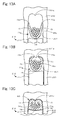
- Fig. 13 is an explanatory diagram showing a state where the holding portion 71g and the core wires 48a are crimped to form a crimp body 80.
- the contact fitting 71 shown in Figs. 10 and 11 and a lead wire 48 having a plurality of core wires 48a are prepared.
- An anvil 210 and a crimper 200 are prepared. As shown in Fig.
- the anvil 210 has a protruding portion 211 protruding upward in the figure.
- the crimper 200 has a recessed portion 201 that is open downward in the figure and into which the protruding portion 211 can be inserted.
- the bottom of the recessed portion 201 (the upper end of the recessed portion 201 in Fig. 12 ) has a protrusion 201a formed in the center thereof, and is formed in a substantially M-shape that curves from both sides of the recessed portion 201 toward the protrusion 201a in the center.
- the holding portion 71g of the contact fitting 71 is placed on the end face of the protruding portion 211 of the anvil 210, and the plurality of core wires 48a of the lead wire 48 are placed on the inner peripheral surface of the bottom portion 74 ( Fig. 12 ).
- the crimper 200 is moved toward the anvil 210, the holding portion 71g, the core wires 48a, and the protruding portion 211 are inserted into the inside of the recessed portion 201, and the crimper 200 is moved further toward the anvil 210 ( Fig. 13A ).
- first distal end portion 72a of the first side portion 72 and the second distal end portion 73a of the second side portion 73 which are located closest to the crimper 200 in the holding portion 71g, approach the bottom of the recessed portion 201.
- the crimper 200 is moved further toward the anvil 210, the first distal end portion 72a and the second distal end portion 73a first come into contact with the bottom of the recessed portion 201, and the first distal end portion 72a and the second distal end portion 73a move along the curvature of the bottom of the recessed portion 201 so as to approach each other.
- the first side portion 72 and the second side portion 73 are thereby curved such that the first distal end portion 72a and the second distal end portion 73a face toward the bottom portion 74 ( Fig. 13B ).
- the crimper 200 is moved further toward the anvil 210, and the crimper 200 and the anvil 210 are pressed toward each other.
- the first distal end portion 72a and the second distal end portion 73a thereby bite into the plurality of core wires 48a, and the plurality of core wires 48a are surrounded and crimped with the bottom portion 74, the first side portion 72, and the second side portion 73 ( Fig. 13C ).
- a crimp body 80 is manufactured.
- parts of the member of the holding portion 71g may be pressed into the spaces between the protruding portion 211 and both side surfaces of the recessed portion 201 to form burrs 75 and 76 on the bottom portion 74 as shown in Fig. 13C .
- the thicknesses T1 and T2 of the first distal end portion 72a and the second distal end portion 73a in the state before crimping are both 70% or less of the thickness Sa of the bottom portion 74. Therefore, the first distal end portion 72a and the second distal end portion 73a easily bite into the plurality of core wires 48a, and the core wires 48a of the lead wire 48 can be fixed more firmly with the bottom portion 74, the first side portion 72, and the second side portion 73. Since the first side portion 72 and the second side portion 73 have a shape that becomes gradually thinner toward the distal end portion 72a, 73a as shown in Fig.
- the first distal end portion 72a and the second distal end portion 73a easily bite into the plurality of core wires 48a. Since the first distal end portion 72a and the second distal end portion 73a easily bite into the plurality of core wires 48a, a crimp body that satisfies the above first to tenth conditions described with reference to Fig. 7 and Fig. 8 when the holding portion 71g is viewed in a section perpendicular to the axial direction of the core wires 48a can be made relatively easily.
- the curved shape of the bottom of the recessed portion 201, the protrusion height of the protrusion 201a, the load when the crimper 200 and the anvil 210 are pressed toward each other, and the like can be preliminarily determined, for example, by experiments such that the first distal end portion 72a and the second distal end portion 73a can bite into the plurality of core wires 48a more easily and such that the first to tenth conditions can be easily satisfied.
- the above-described housing 51 including a first housing 51a and a second housing 51b, and a clamp 90 are prepared, and the sensor element 20 is sandwiched between the first housing 51a and the second housing 51b, with each of the first housing 51a and the second housing 51b holding four contact fittings 71 of crimp bodies 80.
- the sensor element 20 and the plurality of contact fittings 71 are sandwiched between the first housing 51a and the second housing 51b.
- the supporting portion 71b is in contact with the surface of the sensor element 20, and the conduction portion 71c is in contact with the electrode 21.
- the clamp 90 is brought into a state in which it presses the first housing 51a and the second housing 51b toward each other.
- the contact fittings 71 are pressed toward the sensor element 20
- the supporting portions 71b come into contact with the surface of the sensor element 20
- the conduction portions 71c come into contact with and are electrically connected to the electrodes 21 of the sensor element 20
- the supporting portions 71b and the conduction portions 71c are elastically deformed and press the sensor element 20.
- the rubber plug 47 is inserted into the outer cylinder 46 through the open end 46a, the outer cylinder 46 and the rubber plug 47 are reduced in diameter by crimping, and the rubber plug 47 is fixed to the outer cylinder 46. In this way, a gas sensor 10 can be manufactured.
- the contact fitting 71 of this embodiment corresponds to the crimp terminal of the present invention
- the bottom portion 74 corresponds to the bottom portion
- the first side portion 72 corresponds to the first side portion
- the second side portion 73 corresponds to the second side portion
- the holding portion 71g corresponds to the holding portion
- the first distal end portion 72a corresponds to the first distal end portion
- the second distal end portion 73a corresponds to the second distal end portion.
- the thickness T1 of the first distal end portion 72a is 70% or less of the thickness Sa of the bottom portion 74
- the thickness T2 of the second distal end portion 73a is 70% or less of the thickness Sa of the bottom portion 74. Therefore, when the holding portion 71g crimps the plurality of core wires 48a, the first distal end portion 72a and the second distal end portion 73a easily bite into the plurality of core wires 48a. Therefore, the core wires 48a of the lead wire 48 can be fixed more firmly with the bottom portion 74, the first side portion 72, and the second side portion 73.
- the lead wire 48 By firmly fixing the core wires 48a with the holding portion 71g, the lead wire 48 can be prevented from easily coming off after crimping.
- the adhesion between the contact fitting 71 and the core wires 48a and the adhesion between the core wires 48a are made sufficient, and the contact resistance in the crimp part can be prevented from varying.
- the first distal end portion 72a and the second distal end portion 73a bite into the plurality of core wires 48a more easily.
- the strength of the first distal end portion 72a and the second distal end portion 73a can be made high compared to the case where the first distal end portion 72a and the second distal end portion 73a are thinned, for example, by polishing or grinding.
- the crimp body 80 includes a lead wire 48 having a plurality of core wires 48a, and a contact fitting 71.
- the first side portion 72 and the second side portion 73 are curved such that the first distal end portion 72a and the second distal end portion 73a face the bottom portion 74, and the holding portion 71g of the contact fitting 71 thereby surrounds and crimps the plurality of core wires 48a with the bottom portion 74, the first side portion 72, and the second side portion 73.
- the holding portion 71g When the holding portion 71g is viewed in a section perpendicular to the axial direction of the core wires 48a, the crimp body 80 satisfies the first condition (the crimp height CH is 1.20 ⁇ 0.05 mm and the crimp width CW is 1.66 ⁇ 0.05 mm). Therefore, the holding portion 71g is sufficiently compressed in the height direction of the section, and the core wires 48a can be fixed more firmly.
- the crimp body 80 When the holding portion 71g is viewed in a section perpendicular to the axial direction of the core wires 48a, the crimp body 80 satisfies the second condition (the height Ha is 0.15 mm or more). Therefore, the contact (crimping) between the first side portion 72 and the second side portion 73 is made sufficient, and the core wires 48a can be fixed more firmly.
- the crimp body 80 When the holding portion 71g is viewed in a section perpendicular to the axial direction of the core wires 48a, the crimp body 80 satisfies the third condition (the angle ⁇ is 0° or more and 30° or less). Therefore, the first side portion 72 and the second side portion 73 can crimp the core wires 48a in a balanced manner, and the core wires 48a can be fixed more firmly.
- the crimp body 80 When the holding portion 71g is viewed in a section perpendicular to the axial direction of the core wires 48a, the crimp body 80 satisfies the fourth condition (the distance CFA is 0.125 mm or more).
- the distance CFA is smaller than 0.125 mm, the distance between at least one of the first distal end portion 72a side of the first side portion 72 and the second distal end portion 73a side of the second side portion 73 and the bottom portion is small, and some of the core wires 48a may be excessively crushed. This can be prevented by making the distance CFA 0.125 mm or more. That is, by making the distance CFA 0.125 mm or more, the plurality of core wires 48a can be crimped in a balanced manner, and the core wires 48a can be fixed more firmly.
- the crimp body 80 When the holding portion 71g is viewed in a section perpendicular to the axial direction of the core wires 48a, the crimp body 80 satisfies the fifth condition (the distance CFE is 0 mm or more and 0.25 mm or less). Therefore, the first side portion 72 and the second side portion 73 can crimp the core wires 48a in a balanced manner, and the core wires 48a can be fixed more firmly.
- the holding portion 71g When the holding portion 71g is viewed in a section perpendicular to the axial direction of the core wires 48a, the crimp body 80 satisfies the sixth condition (the compression rate CR [%] is 87% or less). Therefore, the holding portion 71g compresses the core wires 48a sufficiently, and the core wires 48a can be fixed more firmly.
- the crimp body 80 When the holding portion 71g is viewed in a section perpendicular to the axial direction of the core wires 48a, the crimp body 80 satisfies the seventh condition (no cracks are generated in rising parts 74a and 74b). Therefore, compared to a case where cracks are generated, the strength of the holding portion 71g is high, and therefore the core wires 48a can be fixed more firmly.
- the crimp body 80 When the holding portion 71g is viewed in a section perpendicular to the axial direction of the core wires 48a, the crimp body 80 satisfies the eighth condition (the burr heights Gh of the burrs 75 and 76 are both 0 mm or more and 0.25 mm or less, and the burrs 75 and 76 are within a region that is closer to the core wires 48a than the lowermost part of the bottom portion 74 in the height direction). If the burrs 75 and 76 are large, the percentage of part of the member forming the bottom portion 74, the first side portion 72, and the second side portion 73 that does not affect the fixing of the core wires 48a increases, and therefore the fixing of the core wires 48a is prone to be insufficient. By satisfying the eighth condition, such an effect of the burrs 75 and 76 can be made relatively small, and the core wires 48a can be fixed more firmly.
- the crimp body 80 satisfies the ninth condition (the burr widths Gb of the burrs 75 and 76 are both 0 mm or more and 0.125 mm or less). Therefore, the above-described effect of the burrs 75 and 76 is relatively small, and the core wires 48a can be fixed more firmly.
- the crimp body 80 When the holding portion 71g is viewed in a section perpendicular to the axial direction of the core wires 48a, the crimp body 80 satisfies the tenth condition (the bottom portion thickness Sb is 0.1875 mm or more). Therefore, the strength of the bottom portion 74 is higher, and therefore the core wires 48a can be fixed more firmly.
- a crimp body 80 is manufactured by using a contact fitting 71 in which the thicknesses T1 and T2 are 70% or less of the thickness Sa of the bottom portion 74 in a state before crimping, curving the first side portion 72 and the second side portion 73 such that the first distal end portion 72a and the second distal end portion 73a face the bottom portion 74, and surrounding and crimping a plurality of core wires 48a with the bottom portion 74, the first side portion 72, and the second side portion 73.
- the first distal end portion 72a and the second distal end portion 73a easily bite into the plurality of core wires 48a, and the core wires 48a of the lead wire 48 can be fixed more firmly with the bottom portion 74, the first side portion 72, and the second side portion 73.
- the thicknesses T1 and T2 are smaller than the diameter of the core wires 48a of the lead wire 48 to be crimped, the present invention is not limited to this, and the thicknesses T1 and T2 may be larger than the diameter of the core wires 48a.
- the thicknesses T1 and T2 are preferably smaller than the diameter of the core wires 48a of the lead wire 48 to be crimped.
- the thicknesses of the first distal end portion 72a and the second distal end portion 73a may change due to crimping. Therefore, the thicknesses of the first distal end portion 72a and the second distal end portion 73a after crimping do not necessarily have to be smaller than the diameter of the core wires 48a.
- the thicknesses T1 and T2 are 70% or less of the thickness Sa of the bottom portion 74.
- the thicknesses of the first distal end portion 72a and the second distal end portion 73a may be 70% or less of the thickness Sa of the bottom portion 74.
- the thicknesses of the first distal end portion 72a and the second distal end portion 73a may change, and the thickness of the bottom portion 74 may change.
- the thicknesses of the first distal end portion 72a and the second distal end portion 73a after crimping do not necessarily have to be 70% or less of the thickness Sb of the bottom portion 74 after crimping.
- the ends of the holding portion 71g of the contact fitting 71 after crimping in the axial direction of the core wires 48a may have a shape such that the holding portion 71g and the core wires 48a are not completely crimped compared to the other part (bell-mouth shape). In this bell-mouthed part, compared to the other part, the change in the thickness of the holding portion 71g due to crimping is small.
- the thicknesses of the first distal end portion 72a and the second distal end portion 73a are 70% or less of the thickness Sa of the bottom portion 74, it can be deemed that, in the contact fitting 71 before crimping, the thicknesses T1 and T2 are 70% or less of the thickness Sa of the bottom portion 74.
- the first distal end portion 72a and the second distal end portion 73a are thinned by compression processing.
- the present invention is not limited to compression processing, and the first distal end portion 72a and the second distal end portion 73a may be thinned by another processing method such as polishing or grinding.
- the thicknesses of the first distal end portion 72a and the second distal end portion 73a after processing may be 70% or less of the thicknesses before processing. Not only the first distal end portion 72a and the second distal end portion 73a but also the whole first side portion 72 and the whole second side portion 73 may be thinned.
- the crimp body 80 when the holding portion 71g is viewed in a section perpendicular to the axial direction of the core wires 48a, the crimp body 80 satisfies all of the first to tenth conditions.
- the present invention is not limited to this. If at least one of the first to tenth conditions are satisfied, the core wires 48a can be fixed more firmly. However, the larger the number of satisfied conditions, the more firmly the core wires 48a can be fixed. It is only necessary to satisfy at least one of the first to tenth conditions in a section of the holding portion 71g.
- the first to tenth conditions be satisfied in a plurality of sections of the holding portion 71g, and it is more preferable that at least one of the first to tenth conditions be satisfied in any section of the holding portion 71g.
- serrations are formed in part of the inner peripheral surface of the bottom portion 74, it is only necessary to satisfy at least one of the first to tenth conditions in a section of part of the holding portion 71g where serrations are not formed, it is preferable that at least one of the first to tenth conditions be satisfied in a plurality of sections, and it is more preferable that at least one of the first to tenth conditions be satisfied in any section.
- the ends of the holding portion 71g after crimping in the axial direction of the core wires 48a are bell-mouthed, it is only necessary to satisfy at least one of the first to tenth conditions in a section of part of the holding portion 71g other than the bell-mouthed parts, it is preferable that at least one of the first to tenth conditions be satisfied in a plurality of sections, and it is more preferable that at least one of the first to tenth conditions be satisfied in any section. If, in the contact fitting 71 before crimping, the thicknesses T1 and T2 are 70% or less of the thickness Sa of the bottom portion 74, the crimp body 80 after crimping may not satisfy any one of the first to tenth conditions. Also in this case, the first distal end portion 72a and the second distal end portion 73a easily bite into the plurality of core wires 48a, and therefore the core wires 48a can be fixed more firmly.
- the thicknesses T1 and T2 are 70% or less of the thickness Sa of the bottom portion 74
- the shape of the contact fitting 71 before crimping is not limited to this as long as the first to tenth conditions are satisfied in the crimp body 80 after crimping.
- the contact fitting 71 shown in Figs. 10 and 11 was made by the above-described manufacturing method, and is designated as Example 1.
- the contact fitting 71 of Example 1 is 0.7 mm in width, 0.2 mm in thickness, and 22 mm in length.
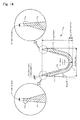
- Fig. 14 is an explanatory diagram showing the dimensions of a section of the holding portion 71g of the contact fitting 71 of Example 1. As shown in Fig.
- the holding portion 71g of Example 1 was 2.1 mm in width, and 2.5 mm in height, the curvature radius of the outer peripheral surface of the bottom portion 74 was 0.7 mm, the thickness Sa of the bottom portion 74 was 0.25 ⁇ 0.02 mm, the serration height was 0.055 ⁇ 0.025 mm, the angle of parts of the first side portion 72 and the second side portion that become gradually thinner toward the distal end portions 72a and 73a was 20°, and the thicknesses T1 and T2 of the first distal end portion 72a and the second distal end portion 73a were 0.05 or more and 0.15 mm or less.
- the contact fitting 71 was made of SUS304.
- FIG. 15 is an explanatory diagram showing the dimensions of a section of the holding portion 71g of the contact fitting 71 of Example 2. As shown in Fig.
- the holding portion 71g of Example 2 was 2.15 ⁇ 0.15 mm in width, and 2.3 ⁇ 0.10 mm in height
- the curvature radius of the inner peripheral surface of the bottom portion 74 was 0.5 mm
- the thickness Sa of the bottom portion 74 was 0.25 ⁇ 0.1 mm
- the serration height was 0.04 ⁇ 0.02 mm
- the angle of parts of the first side portion 72 and the second side portion that become gradually thinner toward the distal end portions 72a and 73a was 21.3° ⁇ 1°
- the thicknesses T1 and T2 of the first distal end portion 72a and the second distal end portion 73a were 0.15 ⁇ 0.02 mm.
- the thicknesses T1 and T2 of the first distal end portion 72a and the second distal end portion 73a are 70% or less of the thickness Sa of the bottom portion 74. More specifically, in Example 1, the thicknesses T1 and T2 are about 20% to about 60% of the thickness Sa of the bottom portion 74. In Example 2, the thicknesses T1 and T2 are about 60% of the thickness Sa of the bottom portion 74.
- Example 1 Five contact fittings 71 of Example 1 described above and five contact fittings 71 of Example 2 described above were made, and core wires 48a of lead wires 48 were crimped with holding portions 71g by the above-described method to make crimp bodies 80 of Examples 1 and 2.
- the lead wires 48 used each included 19 core wires 48a that were 0.2 mm in diameter.
- the load when pressing the crimper 200 and the anvil 210 toward each other was such that the maximum pressing load was within a range of 450 kg ⁇ 4.0%.
- the made crimp bodies 80 were cut perpendicularly to the axial direction of the core wires 48a, and it was checked whether or not the sections satisfy the first to tenth conditions.
- Example 1 Example 2 Condition Average Maximum Minimum Grade Average Maximum Minimum Grade
- the first condition Crimp height CH[mm] 1.20 ⁇ 0.05 1.23 1.25 1.20 ⁇ 1.19 1.20 1.19 ⁇ Crimp width CW[mm] 1.66 ⁇ 0.05 1.66 1.67 1.64 ⁇ 1.67 1.67 1.66 ⁇
- the third condition Angle ⁇ [°] 0 ⁇ 30 6.31 8.46 4.26 ⁇ 3.08 5.35 0.01 ⁇
- the fifth condition Distance CFE[mm] 0 ⁇ 0.25 0.07 0.14 0.02 ⁇ 0.01 0.01 0.00 ⁇
- the sixth condition Compression rate CR[%] ⁇ 87 57 61 55 ⁇ 71 74 67 ⁇
- Example 1 satisfied all of the first to tenth conditions. Although burrs were not measured on Example 2, Example 2 satisfied the first to seventh conditions and the tenth condition. From this, it was found that a crimp body 80 that satisfies the first to tenth conditions can be made relatively easily by making the thicknesses T1 and T2 of the first distal end portion 72a and the second distal end portion 73a 70% of the thickness Sa of the bottom portion 74.
- the resistance to pulling (tensile strength) of the lead wire 48 and the uniformity in the contact resistance between the holding portion 71g and the core wires 48a were measured on the crimp bodies 80 of Examples 1 and 2, and it was confirmed that, compared to a crimp body that does not satisfy any one of conditions 1 to 10, the crimp bodies 80 of Examples 1 and 2 can yield good results.
- the present invention is applicable to a crimp terminal that fixes core wires of a lead wire used in a sensor such as a gas sensor that measures the concentration of gas such as NOx or O 2 .
Landscapes
- Chemical & Material Sciences (AREA)
- Life Sciences & Earth Sciences (AREA)
- Health & Medical Sciences (AREA)
- Biochemistry (AREA)
- General Physics & Mathematics (AREA)
- Electrochemistry (AREA)
- Physics & Mathematics (AREA)
- Analytical Chemistry (AREA)
- Molecular Biology (AREA)
- General Health & Medical Sciences (AREA)
- Chemical Kinetics & Catalysis (AREA)
- Immunology (AREA)
- Pathology (AREA)
- Engineering & Computer Science (AREA)
- Manufacturing & Machinery (AREA)
- Connections Effected By Soldering, Adhesion, Or Permanent Deformation (AREA)
- Manufacturing Of Electrical Connectors (AREA)
Abstract
Description
- The present application claims priority from Japanese Patent Application No.
2013-073711 filed on March 29, 2013 - The present invention relates to a crimp terminal, a crimp body, and a method for manufacturing a crimp body.
- Hitherto, there has been known a crimp terminal having a fixing portion that fixes core wires of a lead wire. For example, Patent Literature 1 describes a crimp terminal including a fixing portion having a bottom wall and a pair of side walls erected from both ends of the bottom wall, wherein both distal end parts of the side walls that are located on the side opposite to the bottom wall are bent toward the bottom wall, and wherein an enclosing portion surrounding core wires of a lead wire is formed by the bottom wall and both the side walls. Patent Literature 1 describes that when the relationship between the maximum width of the fixing portion, the maximum width of the enclosing portion, and the minimum thickness of the bottom wall and the relationship between the maximum height from the bottom wall to the starting point of the side wall farthest from the bottom wall and the maximum height from the starting point to the end of each distal end part satisfy predetermined conditions, the core wires of the lead wire can be fixed firmly.
- PTL 1: Japanese Unexamined Patent Application Publication No.
2007-5202 - When a crimp terminal cannot fix core wires of a lead wire firmly, for example, the lead wire may be prone to come off after crimping. In addition, insufficiency of the adhesion between the crimp terminal and the core wires and the adhesion between the core wires may cause variation in the contact resistance in the crimp terminal part. So, it has been desired to fix core wires of a lead wire more firmly.
- The present invention has been made to solve such a problem, and it is a main object of the present invention to fix core wires of a lead wire more firmly.
- A crimp terminal in the present invention comprises a holding portion including a bottom portion, a first side portion continuous with the bottom portion, and a second side portion continuous with the side of the bottom portion opposite to the first side portion,
wherein the first side portion has a first distal end portion located at the end on the side opposite to the side continuous with the bottom portion, and the thickness of the first distal end portion is 70% or less of the thickness of the bottom portion, and
wherein the second side portion has a second distal end portion located at the end on the side opposite to the side continuous with the bottom portion, and the thickness of the second distal end portion is 70% or less of the thickness of the bottom portion. - In the crimp terminal of the present invention, the thickness of the first distal end portion of the first side portion is 70% or less of the thickness of the bottom portion, and the thickness of the second distal end portion of the second side portion is 70% or less of the thickness of the bottom portion. The holding portion of the crimp terminal can surround and crimp a plurality of core wires of a lead wire with the bottom portion, the first side portion, and the second side portion by curving the first side portion and the second side portion such that the first distal end portion and the second distal end portion face the bottom portion. When performing crimping in this manner, the first distal end portion and the second distal end portion easily bite into the plurality of core wires since the thicknesses of the first distal end portion and the second distal end portion are 70% or less of the thickness of the bottom portion. Therefore, the core wires of the lead wire can be fixed more firmly with the bottom portion, the first side portion, and the second side portion. The smaller the thickness of the first distal end portion and the thickness of the second distal end portion, the more easily the first and second distal end portions bite into the plurality of core wires. However, from the manufacturing viewpoint and the viewpoint of the strength of the first and second distal end portions, the thickness of the first distal end portion and the thickness of the second distal end portion are preferably 40% or more of the thickness of the bottom portion. In the state after the core wires are crimped by the crimp terminal, the thickness of the first distal end portion does not necessarily have to be 70% or less of the thickness of the bottom portion, and the thickness of the second distal end portion does not necessarily have to be 70% or less of the thickness of the bottom portion. In the crimp terminal of the present invention, the thicknesses of the first distal end portion and the second distal end portion may be smaller than the diameter of the core wires of the lead wire to be crimped. In this case, at the time of crimping, the first distal end portion and the second distal end portion bite into the plurality of core wires more easily. In the state after the core wires are crimped by the crimp terminal, the thicknesses of the first distal end portion and the second distal end portion do not necessarily have to be smaller than the diameter of the core wires of the lead wire that are crimped.
- In the crimp terminal of the present invention, the first distal end portion and the second distal end portion may be formed by compression processing. In this case, the strength of the first and second distal end portions can be made high compared to the case where the first and second distal end portions are thinned, for example, by polishing or grinding.
When the first and the second distal end portions are thinned by processing not limited to compression processing, the thicknesses of the first and the second distal end portions after processing may be 70% or less of the thicknesses before processing. - A crimp body in the present invention comprises a lead wire having a plurality of core wires; and
a crimp terminal comprising a holding portion including a bottom portion, a curved first side portion continuous with the bottom portion, and a curved second side portion continuous with the side of the bottom portion opposite to the first side portion,
the first side portion and the second side portion are curved such that a first distal end portion that is the distal end portion of the first side portion and a second distal end portion that is the distal end portion of the second side portion face the bottom portion, and the holding portion thereby surrounds and crimps the plurality of core wires with the bottom portion, the first side portion, and the second side portion, and
when the holding portion is viewed in a section perpendicular to the axial direction of the core wires, in the section, horizontal direction is defined as the direction of a tangent to the curved part of the first side portion and the curved part of the second side portion, height direction is defined as the direction perpendicular to the horizontal direction, a crimp height CH that is the height from the bottom surface of the bottom portion to the tangent is 1.20 ± 0.05 mm and a crimp width CW that is the width in the horizontal direction of the holding portion is 1.66 ± 0.05 mm. - In the crimp body of the present invention, the holding portion is sufficiently compressed in the height direction since the crimp height CH is 1.20 ± 0.05 mm and the crimp width CW is 1.66 ± 0.05 mm in the section of the holding portion. Therefore, the core wires of the lead wire can be fixed more firmly. In this case, the first distal end portion and the second distal end portion may bite into the plurality of core wires. Here, "the first side portion and the second side portion are curved such that a first distal end portion that is the distal end portion of the first side portion and a second distal end portion that is the distal end portion of the second side portion face the bottom portion" describes the direction of the curvature of the
first side portion 72 and thesecond side portion 73. Therefore, the crimp bodies of the present invention also include a crimp body in which the first distal end portion and the second distal end portion do not face thebottom portion 74 in a state after crimping. - In the crimp body of the present invention, in the section, a height Ha that is the distance in the height direction of the contact part between the first side portion and the second side portion may be 0.15 mm or more. In this case, the contact (crimping) between the first side portion and the second side portion is sufficient, and the core wires of the lead wire can be fixed more firmly.
- In the crimp body of the present invention, in the section, an angle α that is the angle between the contact part between the first side portion and the second side portion and the height direction may be 0° or more and 30° or less. In this case, the first side portion and the second side portion can crimp the core wires in a balanced manner, and the core wires of the lead wire can be fixed more firmly.
- In the crimp body of the present invention, in the section, a distance CFA that is the minimum distance in the height direction between the lowermost part of a surface of the bottom portion on the side of the core wires, and the first distal end portion side of the first side portion and the second distal end portion side of the second side portion may be 0.125 mm or more. When the distance CFA is less than 0.125 mm, the distance between at least one of the first distal end portion side of the first side portion and the second distal end portion side of the second side portion and the bottom portion is small, and some of the core wires may be excessively crushed. This can be prevented by making the distance CFA 0.125 mm or more. That is, by making the distance CFA 0.125 mm or more, the plurality of core wires can be crimped in a balanced manner, and the core wires of the lead wire can be fixed more firmly.
- In the crimp body of the present invention, in the section, a distance CFE that is the distance in the height direction between the tangent in the horizontal direction to the first distal end portion side of the first side portion and the tangent in the horizontal direction to the second distal end portion side of the second side portion may be 0 mm or more and 0.25 mm or less. In this case, the first side portion and the second side portion can crimp the core wires in a balanced manner, and the core wires of the lead wire can be fixed more firmly. The smaller the value of the distance CFE, the more preferable.
- In the crimp body of the present invention, in the section, when compression rate CR [%] = (the area of the region surrounded by the bottom portion, the first side portion, and the second side portion) / {(the cross-sectional area of each core wire before crimping) x (the number of the crimped core wires)} x 100, the compression rate CR [%] may be 87% or less. In this case, the crimp terminal compresses the core wires sufficiently, and the core wires of the lead wire can be fixed more firmly.
The lower the compression rate CR, the more firmly the core wires can be fixed. The lower limit of the compression rate CR is determined by, for example, the material and number of the core wires and the force applied during crimping. The compression rate CR may be, for example, 50% or more. - In the crimp body of the present invention, in the section, it is preferable that no cracks are generated in rising parts on the side of the core wires from the bottom portion to the first side portion and the second side portion. In this case, compared to the case where cracks are generated, the strength of the holding portion is high, and therefore the core wires of the lead wire can be fixed more firmly.
- In the crimp body of the present invention, in the section, a burr height Gh that is the height of a burr on the bottom portion may be 0 mm or more and 0.25 mm or less, and the burr may be within a region that is closer to the core wires than the lowermost part of the bottom portion in the height direction. When crimping the core wires using the crimp terminal, a burr may be generated on the bottom portion. This burr contributes little to the fixing of the core wires. The larger the burr, the higher the percentage of part of the member forming the bottom portion and the first and second side portions that does not affect the fixing of the core wires, and therefore the more insufficient the fixing of the core wires. The larger the burr, the more likely the burr is to damage members around the holding portion (for example, a sheath of another lead wire, and a rubber plug that seals the area around the holding portion). When the burr height Gh is 0 mm or more and 0.25 mm or less, such an effect of the burr can be made relatively small. The smaller the value of the burr height Gh, the more preferable. The fact that the burr height Gh is 0 mm means that no burr is generated. When there are a plurality of burrs, it is preferable that the burr heights Gh of the plurality of burrs be all 0 mm or more and 0.25 mm or less.
- In the crimp body of the present invention, in the section, a burr width Gb that is the width in the horizontal direction of a burr on the bottom portion may be 0 mm or more and 0.125 mm or less. When the burr width Gb is 0 mm or more and 0.125 mm or less, the above-described effect of the burr can be made relatively small. The smaller the value of the burr width Gb, the more preferable. The fact that the burr width Gb is 0 mm means that no burr is generated. When there are a plurality of burrs, it is preferable that the burr widths Gb of the plurality of burrs be all 0 mm or more and 0.125 mm or less.
- In the crimp body of the present invention, in the section, a bottom portion thickness Sb that is the thickness of the bottom portion may be 0.1875 mm or more. In this case, the strength of the bottom portion is higher, and therefore the core wires of the lead wire can be fixed more firmly.
- The crimp body of the present invention described above can be obtained relatively easily, for example, by crimping a plurality of core wires using the crimp terminal of the present invention described above.
- A method for manufacturing a crimp body includes a crimp terminal including a holding portion including a bottom portion, a first side portion continuous with the bottom portion, and a second side portion continuous with the side of the bottom portion opposite to the first side portion, wherein the first side portion has a first distal end portion located at the end on the side opposite to the side continuous with the bottom portion, and the thickness of the first distal end portion is 70% or less of the thickness of the bottom portion, and wherein the second side portion has a second distal end portion located at the end on the side opposite to the side continuous with the bottom portion, and the thickness of the second distal end portion is 70% or less of the thickness of the bottom portion, the method comprising the steps of:
- (a) preparing the crimp terminal and a lead wire having a plurality of core wires; and
- (b) surrounding and crimping the plurality of core wires with the bottom portion, the first side portion, and the second side portion by curving the first side portion and the second side portion such that the first distal end portion and the second distal end portion face the bottom portion.
- In the method for manufacturing a crimp body of the present invention, a crimp terminal in which, as with the crimp terminal of the present invention described above, the thickness of the first distal end portion is 70% or less of the thickness of the bottom portion and the thickness of the second distal end portion is 70% or less of the thickness of the bottom portion is prepared, and crimping of the plurality of core wires is performed using this. That is, in a state before crimping, the thickness of the first distal end portion of the first side portion is 70% or less of the thickness of the bottom portion,
and the thickness of the second distal end portion of the second side portion is 70% or less of the thickness of the bottom portion. Using this crimp terminal, the first side portion and the second side portion are curved such that the first distal end portion and the second distal end portion face the bottom portion, and the plurality of core wires are surrounded and crimped with the bottom portion, the first side portion, and the second side portion. Therefore, the first distal end portion and the second distal end portion easily bite into the plurality of core wires, and the core wires of the lead wire can be fixed more firmly with the bottom portion, the first side portion, and the second side portion. - In the method for manufacturing a crimp body of the present invention, in the step (a), the crimp terminal in which the thicknesses of the first distal end portion and the second distal end portion are smaller than the diameter of the core wires of the lead wire may be prepared. In this case, in the step of crimping, the first distal end portion and the second distal end portion bite into the plurality of core wires more easily.
-
-
Fig. 1 is a longitudinal sectional view of agas sensor 10 of the embodiment. -
Fig. 2 is a perspective view of aconnector 50. -
Fig. 3 is an exploded perspective view showing ahousing 51 of theconnector 50. -
Fig. 4 is a sectional view taken along line A-A ofFig. 2 . -
Fig. 5 is a sectional view taken along line B-B ofFig. 4 . -
Fig. 6 is an explanatory diagram showing the positional relationship betweencontact fittings 71 and asensor element 20 as viewed from thefirst housing 51a side. -
Fig. 7 is a sectional view taken along line C-C ofFig. 4 . -
Fig. 8 is an explanatory diagram of aregion 77 surrounded by abottom portion 74, afirst side portion 72, and asecond side portion 73. -
Fig. 9 is an explanatory diagram showing the state of a contact fitting 71 before bending processing. -
Fig. 10 is a perspective view of the contact fitting 71 after bending processing. -
Fig. 11 is a sectional view taken along line D-D ofFig. 10 . -
Fig. 12 is an explanatory diagram showing a state in which a holdingportion 71g andcore wires 48a are disposed between acrimper 200 and ananvil 210. -
Fig. 13 is an explanatory diagram showing a state in which the holdingportion 71g and thecore wires 48a are crimped to form acrimp body 80. -
Fig. 14 is an explanatory diagram showing the section size of a holdingportion 71g of a contact fitting 71 of Example 1. -
Fig. 15 is an explanatory diagram showing the section size of a holdingportion 71g of a contact fitting 71 of Example 2. - Embodiments for carrying out the present invention will now be described with reference to the drawings.
-
Fig. 1 is a longitudinal sectional view of agas sensor 10 having a contact fitting 71 that is an embodiment of a crimp terminal of the present invention.Fig. 2 is a perspective view of aconnector 50, andFig. 3 is an exploded perspective view showing ahousing 51 of theconnector 50.Fig. 4 is a sectional view taken along line A-A ofFig. 2 ,Fig. 5 is a sectional view taken along line B-B ofFig. 4 , andFig. 6 is an explanatory diagram showing the positional relationship betweencontact fittings 71 and asensor element 20 as viewed from afirst housing 51a side. - As shown in
Fig. 1 , thegas sensor 10 includes thesensor element 20 that measures a predetermined gas component in gas to be measured, aprotective cover 30 that protects one end of thesensor element 20, and asensor assembly 40 that includes theconnector 50 electrically connected to thesensor element 20. Thegas sensor 10 is attached, for example, to an exhaust gas pipe of a vehicle, and is used to measure gas components such as NOx and O2 contained in exhaust gas as gas to be measured. - The
sensor element 20 is an elongated element having a plate-like shape, and is formed by laminating, for example, six ceramic substrates that are oxygen ion conductive solid electrolyte layers of zirconia (ZrO2) or the like. The end of thesensor element 20 that is closest to theprotective cover 30 will be referred to as distal end, and the end of thesensor element 20 that is closest to theconnector 50 will be referred to as proximal end. On surfaces (a first surface that is the upper surface inFig. 5 and a second surface that is the lower surface inFig. 5 ) of the proximal end of thesensor element 20, fourfirst surface electrodes 21a and foursecond surface electrodes 21b are formed as shown inFig. 5 . Thefirst surface electrodes 21a and thesecond surface electrodes 21b will be collectively referred to as electrodes 21. The electrodes 21 are for applying a voltage to thesensor element 20, and for taking out electromotive force or current generated according to the concentration of a gas component detected by thesensor element 20, and are electrically connected through electrical paths inside thesensor element 20 to electrodes (not shown) in the distal end of thesensor element 20. The positions of thefirst surface electrodes 21a and thesecond surface electrodes 21b will be described later. - The
protective cover 30 is disposed so as to surround the distal end of thesensor element 20 as shown inFig. 1 . Theprotective cover 30 includes an innerprotective cover 31 that covers the distal end of thesensor element 20, and an outerprotective cover 32 that covers the innerprotective cover 31. The innerprotective cover 31 is formed in a cylindrical shape, and has an innerprotective cover hole 31a for introducing gas to be measured to the distal end of thesensor element 20. The outerprotective cover 32 is formed in a bottomed cylindrical shape, and has, in the side surface thereof, outerprotective cover holes 32a for introducing gas to be measured. The innerprotective cover 31 and the outerprotective cover 32 are made of metal such as stainless steel. - The
sensor assembly 40 includes amain fitting 41 made of meal, aninner cylinder 42 and anouter cylinder 46 that are cylindrical and that are fixed to themain fitting 41 by welding, and theconnector 50 connected to the proximal end of thesensor element 20. Themain fitting 41 can be attached, for example, to an exhaust gas pipe of a vehicle with anexternal thread portion 41a. A plurality ofceramic supporters 43a to 43c, andceramic powder ceramic supporters ceramic supporters inner cylinder 42, and these are sealed between ametal ring 45 and the inner wall of themain fitting 41. Theouter cylinder 46 covers the peripheries of theinner cylinder 42, thesensor element 20, and theconnector 50, and leadwires 48 connected to theconnector 50 are pulled out through anopen end 46a to the outside. Thelead wires 48 are electrically connected through theconnector 50 to the electrodes 21 of thesensor element 20. Gaps between theouter cylinder 46 and thelead wires 48 are sealed by arubber plug 47. - Next, the
connector 50 will be described in detail. As shown, theconnector 50 includes thefirst housing 51a and asecond housing 51b that are made of ceramic such as sintered alumina body, thecontact fittings 71 that are held by thefirst housing 51a or thesecond housing 51b and that face and are in contact with the electrodes 21 of thesensor element 20 on a one-to-one basis, and ametal clamp 90 that clamps and fixes thefirst housing 51a and thesecond housing 51b. - The
first housing 51a and thesecond housing 51b are members that each hold fourcontact fittings 71 arranged in a direction (Y direction) perpendicular to the longitudinal direction of the contact fittings 71 (X direction). Thefirst housing 51a and thesecond housing 51b have the same shape, so the same reference numerals will be used to designate the same components in thefirst housing 51a and thesecond housing 51b. Thefirst housing 51a and thesecond housing 51b will be collectively referred to ashousings 51. Eachhousing 51 includes four lockinggrooves 52 that lock thecontact fittings 71, fourinsertion holes 53 into which thecontact fittings 71 are inserted, and locking portions 54 (seeFig. 4 ) formed in the insertion holes 53 and locking thecontact fittings 71. Eachhousing 51 has a protrudingportion 55 on one side thereof in the Y direction, and restrictingmembers first housing 51a and thesecond housing 51b on the other side thereof, with thesensor element 20 interposed therebetween (seeFig. 2 and Fig. 3 ). The protrudingportion 55 is inserted into the recess between the restrictingmember 56 and the restrictingmember 57 of theopposite housing 51, and the relative positions of thefirst housing 51a and thesecond housing 51b in the X direction can thereby be fixed. - The
contact fittings 71 are metal members held by thehousings 51 at positions facing the electrodes 21 of thesensor element 20 on a one-to-one basis, and each include, as shown inFig. 4 , adistal end portion 71a that has a curved shape and that is thereby locked in the lockinggroove 52, a supportingportion 71b that is curved and protruded toward thesensor element 20, aconduction portion 71c that is curved and protruded toward thesensor element 20 and that is thereby in contact with the electrode 21, anupright portion 71d that is inserted into theinsertion hole 53, acurved portion 71f that is pulled out to the outside of theconnector 50, and a holdingportion 71g that crimps and holds a plurality ofcore wires 48a of alead wire 48 outside theconnector 50. The holdingportion 71g and thelead wire 48 crimped by the holdingportion 71g will be collectively referred to ascrimp body 80. The supportingportion 71b and theconduction portion 71c are arranged along the longitudinal direction of the contact fitting 71 (the X direction inFig. 4 ), and theconduction portion 71c is disposed at a position closer to the holdingportion 71g than the supportingportion 71b. The supportingportion 71b and theconduction portion 71c are both formed so as to be able to be elastically deformed, and both have a spring constant within a range, for example, of 500 to 4000 N/mm. Theupright portion 71d has ahook portion 71e that has a curved shape and that is thereby locked to the lockingportion 54. Theconduction portions 71c of thecontact fittings 71 held by thefirst housing 51a face and are in contact with thefirst surface electrodes 21a of thesensor element 20 on a one-to-one basis, and theconduction portions 71c of thecontact fittings 71 held by thesecond housing 51b face and are in contact with thesecond surface electrodes 21b of thesensor element 20 on a one-to-one basis (seeFig. 4 and Fig. 5 ). - The positional relationship between the
contact fittings 71 and the electrodes 21 of thesensor element 20 will be described. As shown inFig. 4 andFig. 6 , thefirst surface electrodes 21a of thesensor element 20 extend from the proximal end of the sensor element 20 (the right end inFig. 4 andFig. 6 ) to a position between theconduction portions 71c and the supportingportions 71b. Of the fourfirst surface electrodes 21a arranged in the Y direction, the central twofirst surface electrodes 21a are electrically connected to throughholes 21e that are formed for electrical connection to the above-described electrical paths inside thesensor element 20. As shown in Fig.
6, each throughhole 21e is formed at a position between theconduction portion 71c and the supportingportion 71b. The positional relationship between thesecond surface electrodes 21b and thecontact fittings 71, and the positions of throughholes 21e electrically connected to thesecond surface electrodes 21b are the same as this, so the description thereof will be omitted. - The holding
portion 71g of the contact fitting 71 will be described in detail.Fig. 7 is a sectional view taken along line C-C ofFig. 4 .Fig. 7 is a section perpendicular to the axial direction of thecore wires 48a (the X direction inFig. 4 ).Fig. 7A is an explanatory diagram showing the whole section of the holdingportion 71g, andFig. 7B is an enlarged view of the contact part between thefirst side portion 72 and thesecond side portion 73 inFig. 7A (the part surrounded by the dashed circle). As shown inFig. 7A , the holdingportion 71g includes abottom portion 74, afirst side portion 72 that is continuous with thebottom portion 74 and that is erected from thebottom portion 74, and asecond side portion 73 that is continuous with thebottom portion 74 and that is erected from thebottom portion 74. Thefirst side portion 72 is continuous with the left side of thebottom portion 74 inFig. 7 , and thesecond side portion 73 is continuous with the side of thebottom portion 74 opposite to the first side portion 72 (the right side inFig. 7 ). Thefirst side portion 72 has a firstdistal end portion 72a located at the end on the side opposite to the side continuous with thebottom portion 74. Thesecond side portion 73 has a seconddistal end portion 73a located at the end on the side opposite to the side continuous with thebottom portion 74. - In the holding
portion 71g, in the section shown inFig. 7 , thefirst side portion 72 and thesecond side portion 73 are curved such that the firstdistal end portion 72a of thefirst side portion 72 and the seconddistal end portion 73a of thesecond side portion 73 face thebottom portion 74. A plurality of (19 in this embodiment) core wires are thereby surrounded and crimped with thebottom portion 74, thefirst side portion 72, and thesecond side portion 73. By this crimping, the holdingportion 71g and thecore wires 48 are electrically connected with each other, and form acrimp body 80 including the holdingportion 71g and thelead wire 48. The part of thefirst side portion 72 on the side opposite to thebottom portion 74 and the part of thesecond side portion 73 on the side opposite to thebottom portion 74 are curved so as to approach each other. The firstdistal end portion 72a and the seconddistal end portion 73a bite into the plurality ofcore wires 48a of thelead wire 48. "Thefirst side portion 72 and thesecond side portion 73 are curved such that the firstdistal end portion 72a of thefirst side portion 72 and the seconddistal end portion 73a of the second side portion 73 'face the bottom portion 74'" describes the direction of curvature of thefirst side portion 72 and thesecond side portion 73, and the firstdistal end portion 72a and the seconddistal end portion 73a do not necessarily have to face thebottom portion 74 in the state after crimping. For example, like the seconddistal end portion 73a inFig. 7A , they may face in a direction different from the direction toward the bottom portion 74 (to the upper right in the figure). - The holding
portion 71g is formed so as to satisfy predetermined first to tenth conditions in the section shown inFig. 7 . The first to tenth conditions will be described with reference toFig. 7 below. First, as a premise, the horizontal direction and height direction in the section shown inFig. 7 will be defined. First, horizontal direction is defined as the direction of a tangent Lt1 to the curved part of thefirst side portion 72 and the curved part of thesecond side portion 73 in the section shown inFig. 7 . The tangent Lt1 to the curved part of thefirst side portion 72 and the curved part of thesecond side portion 73 is a line connecting the vertices of the curved parts of thefirst side portion 72 and thesecond side portion 73 on the side far from the bottom portion 74 (the upper side inFig. 7 ) as shown inFig. 7A . In the horizontal direction, the side of thefirst side portion 72 will be referred to as leftward direction, and the side of thesecond side portion 73 will be referred to as rightward direction. Height direction is defined as the direction perpendicular to the horizontal direction. In the height direction, the side of thebottom portion 74 will be referred to as downward direction, and the side of thefirst side portion 72 and thesecond side portion 73 will be referred to as upward direction. - The first condition is that "the crimp height CH is 1.20 ± 0.05 mm, and the crimp width is 1.66 ± 0.05 mm." Here, the crimp height CH is the height from the bottom surface of the
bottom portion 74 to the tangent Lt (seeFig. 7A ). The crimp width CW is the width in the horizontal direction of the holdingportion 71g (seeFig. 7A ). - The second condition is that "the height Ha is 0.15 mm or more." Here, the height Ha is the distance in the height direction of the contact part between the
first side portion 72 and the second side portion 73 (seeFig. 7B ). InFig. 7B , points P1 and P2 are the ends of the contact part between thefirst side portion 72 and thesecond side portion 73. Therefore, the height Ha can be obtained as the distance in the height direction between the points P1 and P2. The height Ha, although it is not particularly limited, may be, for example, 0.30 mm or less. - The third condition is that "the angle α is 0° or more and 30° or less." Here, the angle α is the angle between the contact part between the
first side portion 72 and thesecond side portion 73 and the height direction (seeFig. 7B ). As shown inFig. 7B , the contact part between thefirst side portion 72 and thesecond side portion 73 is not limited to a straight line and can be a curved line. So, the angle α is defined as the angle between the straight line connecting the points P1 and P2 at both ends of the contact part and the height direction. - The fourth condition is that "the distance CFA is 0.125 mm or more." Here, the distance CFA is the minimum distance in the height direction between the lowermost part (the lowermost part in
Fig. 7A ) of the surface of thebottom portion 74 on the side of the core wires (the upper surface of thebottom portion 74 inFig. 7A ), and the firstdistal end portion 72a side of thefirst side portion 72 and the seconddistal end portion 73a side of the second side portion 73 (seeFig. 7A ). In other words, the distance CFA is the distance between the tangent Lt5 parallel to the horizontal direction to the lowermost part of the upper surface of thebottom portion 74, and one of the tangent Lt 2 in the horizontal direction to the firstdistal end portion 72a side of thefirst side portion 72 and the tangent Lt 3 in the horizontal direction to the seconddistal end portion 73a side of thesecond side portion 73 that is closer to the tangent Lt5. InFig. 7A , the seconddistal end portion 73a side of thesecond side portion 73 bites deeper than the firstdistal end portion 72a side of thefirst side portion 73. Therefore, the distance CFA is the minimum distance in the height direction between the lowermost part of the upper surface of thebottom portion 74 and the seconddistal end portion 73a side of the second side portion 73 (the distance between the tangent Lt5 and the tangent Lt3). When the firstdistal end portion 72a bites (is entangled) into the plurality ofcore wires 48a as shown inFig. 7A , "the firstdistal end portion 72a side of thefirst side portion 72" may be defined as "the part of thefirst side portion 72 that bites (is entangled) into the plurality ofcore wires 48a." Similarly, when the seconddistal end portion 73a bites (is entangled) into the plurality ofcore wires 48a as shown inFig. 7A , "the seconddistal end portion 73a side of thesecond side portion 73" may be defined as "the part of thesecond side portion 73 that bites (is entangled) into the plurality ofcore wires 48a." When serrations (to be described in detail later) are formed in part of the inner peripheral surface (the surface on the side of thecore wires 48a) of thebottom portion 74, the distance CFA is obtained in the section of the part where serrations are not formed. However, when serrations are formed in the whole inner peripheral surface of thebottom portion 74, the distance CFA is obtained in the section of the part where serrations are formed. The distance CFA, although it is not particularly limited, may be, for example, 0.40 mm or less. - The fifth condition is that "the distance CFE is 0 mm or more and 0.25 mm or less." Here, the distance CFE is the distance in the height direction between the tangent Lt 2 in the horizontal direction to the first
distal end portion 72a side of thefirst side portion 72 and the tangent Lt 3 in the horizontal direction to the seconddistal end portion 73a side of the second side portion 73 (seeFig. 7A ). The tangent Lt2 is a tangent that is tangent to the lower end of the firstdistal end portion 72a side of thefirst side portion 72 as shown inFig. 7A ). Similarly, the tangent Lt3 is a tangent that is tangent to the lower end of the seconddistal end portion 73a side of thesecond side portion 73 as shown inFig. 7A ). - The sixth condition is that "the compression rate CR [%] is 87% or less." Here, the compression rate CR [%] = (the area of the region surrounded by the
bottom portion 74, thefirst side portion 72, and the second side portion 73) / {(the cross-sectional area of eachcore wire 48a before crimping) x (the number of the crimpedcore wires 48a)} x 100.Fig. 8 is an explanatory diagram of theregion 77 surrounded by thebottom portion 74, thefirst side portion 72, and thesecond side portion 73.Fig. 8 shows the same section asFig. 7A . The area of the hatchedregion 77 shown inFig. 8 is "the area of the region surrounded by thebottom portion 74, thefirst side portion 72, and thesecond side portion 73." The lower limit of compression rate CR is determined by, for example, the material and number of thecore wires 48a and the force applied during crimping. The compression rate CR may be, for example, 50% or more. - The seventh condition is that "no cracks are generated in rising parts on the side of the
core wires 48a from thebottom portion 74 to thefirst side portion 72 and thesecond side portion 73." InFig. 7A , the risingpart 74a is "the rising part on the side of thecore wires 48a from thebottom portion 74 to thefirst side portion 72." The rising part 74b is "the rising part on the side of thecore wires 48a from thebottom portion 74 to thesecond side portion 73." - The eighth condition is that "the burr height Gh of the
bottom portion 74 is 0 mm or more and 0.25 mm or less, and the burr is within a region that is closer to thecore wires 48a than the lowermost part (the lowermost surface) of thebottom portion 74 in the height direction." The fact that the burr height Gh is 0 mm means that no burr is generated. As described in detail later, when thecore wires 48a are crimped by the holdingportion 71g, aburr 75 and aburr 76 may be generated at both ends of thebottom portion 74 as shown inFig. 7A . The heights of theburr 75 and theburr 76 from thebottom portion 74 are referred to as burr heights Gh. When there are a plurality of burrs as in this embodiment, the eighth condition is deemed to be satisfied when the burr heights Gh of the burrs are all within the above range. "The burr is within a region that is closer to thecore wires 48a than the lowermost part of thebottom portion 74 in the height direction" means that "there is no burr below a tangent Lt4 that is tangent to the lowermost part of thebottom portion 74 and that is parallel to the horizontal direction." InFig. 7A , "theburrs core wires 48a than the lowermost part of thebottom portion 74 in the height direction." - The ninth condition is that "the burr widths Gb of the
bottom portion 74 are all 0 mm or more and 0.125 mm or less." Here, the burr widths Gb are the widths in the horizontal direction of theburrs 75 and 76 (seeFig. 7A ). The fact that the burr width Gb is 0 mm means that no burr is generated. When there are a plurality of burrs as in this embodiment, the ninth condition is deemed to be satisfied when the burr widths Gb of the burrs are all within the above range. - The tenth condition is that "the bottom portion thickness Sb is 0.1875 mm or more." Here, the bottom portion thickness Sb is the thickness in the height direction of the part of contact point P3 between the above tangent Lt4 and the bottom portion 74 (see
Fig. 7A ). When serrations (to be described in detail later) are formed in part of the inner peripheral surface (the surface on the side of thecore wires 48a) of thebottom portion 74, the bottom portion thickness Sb is obtained as the thickness in the section of the part where serrations are not formed. However, when serrations are formed in the whole inner peripheral surface of thebottom portion 74, the bottom portion thickness Sb is obtained as the thickness in the section of the part where serrations are formed. The bottom portion thickness Sb, although it is not particularly limited, may be, for example, 0.30 mm or less. - The holding
portion 71g of this embodiment satisfies all of the above-described first to tenth conditions in the section ofFig. 7 . In this case, the holdingportion 71g can fix thecore wires 48a of thelead wire 48 more firmly. In addition, in the section ofFig. 7 , it is preferable that the number of spaces between thecore wires 48a be small. The smaller the number of spaces, the more hardly thecore wires 48a are displaced, and the more firmly thecore wires 48a can be fixed. When the first to tenth conditions are all satisfied, the number of spaces is preferably one or less (up to one space is acceptable). - The
clamp 90 is made by bending a metal plate as shown inFig. 2 andFig. 5 , and has an elastic force capable of clamping thefirst housing 51a and thesecond housing 51b and pressing them toward each other. When thefirst housing 51a and thesecond housing 51b are clamped by this elastic force, the restrictingmembers first housing 51a come into contact with thesecond housing 51b, and the restrictingmembers second housing 51b come into contact with thefirst housing 51a. The distance between thefirst housing 51a and thesecond housing 51b is thereby fixed. When theclamp 90 clamps thefirst housing 51a and thesecond housing 51b with thesensor element 20 and thecontact fittings 71 sandwiched between thefirst housing 51a and thesecond housing 51b such that theconduction portions 71c of thecontact fittings 71 face thefirst surface electrodes 21a or thesecond surface electrodes 21b of thesensor element 20, the supportingportions 71b and theconduction portions 71c are elastically deformed by the pressing force from theclamp 90 and clamp and fix thesensor element 20. At this time, since the supportingportions 71b and theconduction portions 71c are elastically deformed, thesensor element 20 can be reliably clamped and fixed by the resulting pressing force. Since theconduction portions 71c are elastically deformed, the electrical contact between theconduction portions 71c and the electrodes 21 can be maintained more reliably. - Next, a method for manufacturing the contact fitting 71 will be described. The contact fitting 71 is manufactured by punching and bending a metal plat.
Fig. 9 is an explanatory diagram showing the state of the contact fitting 71 before bending.Fig. 10 is a perspective view of the contact fitting 71 after bending.Fig. 11 is a sectional view taken along line D-D ofFig. 10 . First, as shown inFig. 9 , a metal plate is punched into a shape having a substantially rectangularmetal plate portion 100, ametal piece 110 continuous with a long side of themetal plate portion 100, and substantiallyrectangular metal pieces region 100g at one end of themetal plate portion 100. Themetal piece 122 is located so as to be continuous with the side of theregion 100g opposite to themetal piece 123. Next,serrations 78 are formed in the surfaces of theregion 100g and themetal pieces Fig. 9 . Although, in this embodiment, as shown, threeserrations 78 are formed, the number ofserrations 78 is not limited to this, andserrations 78 may not be formed. Next,regions metal plate portion 100 are curved toward the near side ofFig. 9 to form thedistal end portion 71a and thecurved portion 71f shown inFig. 4 , andregions Fig. 9 to form the supportingportion 71b and theconduction portion 71c shown inFig. 4 . Aregion 111 of themetal piece 110 is bent along a straight line 111a toward the near side until it becomes parallel to the direction toward the near side ofFig. 9 , aregion 112 of themetal piece 110 is bent along astraight line 112a toward the inside of themetal plate portion 100, and aregion 113 of themetal piece 110 is curved along the longitudinal direction of themetal plate portion 100 toward thecurved portion 71f to form thehook portion 71e. Thus, themetal piece 110 is bent to form theupright portion 71d. As shown inFig. 9 and Fig. 10 ,notches 101 having a depth greater than or equal to the thickness of theregion 111 are formed in themetal plate portion 100 so that when theregion 111 is bent along the straight line 111a, theregion 111 is within a region just above thesurface 102 of the metal plate portion 100 (seeFig. 10 ). Themetal pieces Fig. 9 to form the holdingportion 71g having a substantially U-shaped cross-section. At this time, the end of each of themetal pieces region 100g. When, as in this embodiment,serrations 78 are formed in part of theregion 100g, the compression processing of the end of each of themetal pieces region 100g whereserrations 78 are not formed. However, whenserrations 78 are formed in thewhole region 100g, the compression processing of the end of each of themetal pieces region 100g whereserrations 78 are formed. In this way, the contact fitting 71 having a three-dimensional shape shown inFig. 10 andFig. 11 is manufactured. - The shape of the holding
portion 71g of the thus manufactured contact fitting 71 after bending processing, that is, the contact fitting 71 before crimpingcore wires 48a will be described in detail. In the state before crimping, as described above, the holdingportion 71g is formed in a substantially U-shape (seeFig. 10 andFig. 11 ). Theregion 100g inFig. 9 becomes thebottom portion 74, themetal piece 122 inFig. 9 becomes thefirst side portion 72, and themetal piece 123 becomes thesecond side portion 73. Since the end of each of themetal pieces Fig. 9 on the side opposite to the side continuous with the bottom portion is thinned by compression processing, the firstdistal end portion 72a, which is the end of thefirst side portion 72 on the side opposite to the side continuous with the bottom portion, is thinned, and the seconddistal end portion 73a, which is the end of thesecond side portion 73 on the side opposite to the side continuous with the bottom portion, is thinned (seeFig. 11 ). The thickness T1 of the firstdistal end portion 72a and the thickness T2 of the second distal end portion are formed so as to be 70% or less of the thickness of theregion 100g inFig. 9 as described above, and therefore the thicknesses T1 and T2 are both 70% or less of the thickness Sa of thebottom portion 74. In this embodiment, the thicknesses T1 and T2 are both smaller than the diameter of thecore wires 48a of thelead wire 48 before crimping. The smaller the thicknesses T1 and T2, the more easily the firstdistal end portion 72a and the seconddistal end portion 73a bite into the plurality ofcore wires 48a. However, from the manufacturing viewpoint and the viewpoint of the strength of the firstdistal end portion 72a and the seconddistal end portion 73a, the thicknesses T1 and T2 are preferably 40% or more of the thickness of the bottom portion. When, as shown inFig. 10 ,serrations 78 are formed in part of the inner peripheral surface (the upper surface inFig. 11 ) of thebottom portion 74, the thickness Sa is obtained as the thickness in the section of the part whereserrations 78 are not formed (seeFig. 11 ). However, whenserrations 78 are formed in the whole inner peripheral surface of thebottom portion 74, the bottom portion thickness Sa is obtained as the thickness in the section of the part whereserrations 78 are formed. Although, in this embodiment, as shown inFig. 11 , thefirst side portion 72 has a shape that becomes gradually thinner toward the firstdistal end portion 72a, thefirst side portion 72 may have another shape as long as the thickness T1 of the firstdistal end portion 72a is 70% or less of the thickness Sa. The same is true on thesecond side portion 73. The thickness Sa, although it is not particularly limited, may be, for example, 0.10 mm to 0.40 mm. The diameter ofcore wires 48a before crimping is, for example, 0.126 mm to 0.623 mm, and the number ofcore wires 48a in alead wire 48 is, for example, 2 to 40. - Next, a method for manufacturing a
gas sensor 10 employingcontact fittings 71 after bending processing shown inFig. 10 andFig. 11 will be described. First, amain fitting 41 and aninner cylinder 42 are coaxially joined together by welding, the inside thereof is filled with aceramic supporter 43a,ceramic powder 44a, aceramic supporter 43b,ceramic powder 44b, and aceramic supporter 43c in this order from themain fitting 41 side, and then ametal ring 45 is inserted. Next, asensor element 20 is prepared, and thesensor element 20 is passed through theceramic supporter 43c,ceramic powder 44b,ceramic supporter 43b,ceramic powder 44a, andceramic supporter 43a in this order from themetal ring 45 side. Holes through which thesensor element 20 can be passed are preliminarily formed in theceramic supporters 43a to 43c, theceramic powder metal ring 45. Themetal ring 45 and themain fitting 41 are pressed toward each other to compress theceramic powder inner cylinder 42 on the outer side (the upper side inFig. 1 ) of themetal ring 45 is reduced in diameter by crimping processing. Further, part of theinner cylinder 42 in which theceramic powder 44b is disposed is reduced in diameter by crimping processing. Thus, a primary assembly including themain fitting 41 and thesensor element 20 is obtained. - After the primary assembly is obtained, an inner
protective cover 31 and an outerprotective cover 32 are attached to themain fitting 41 by welding to form aprotective cover 30, and anouter cylinder 46 is attached to themain fitting 41 by welding. Next, a plurality of (eight in this embodiment)contact fittings 71 after bending shown inFig. 10 andFig. 11 are prepared, and a plurality of (eight in this embodiment)lead wires 48 and arubber plug 47 having a through-hole 47a formed therein are prepared. Next, the plurality oflead wires 48 are passed through the through-hole 47a of therubber plug 47, then thecore wires 48a of the plurality oflead wire 48 are surrounded and crimped with the holdingportions 71g of thecontact fittings 71, and thecontact fittings 71 and thelead wires 48 are thereby electrically connected. The eightcontact fittings 71 and the eightlead wires 48 are each crimped, and eightcrimp bodies 80 each including a contact fitting 71 and alead wire 48 connected to each other are thereby manufactured. - The manufacturing of a
crimp body 80 including a contact fitting 71 and alead wire 48 will be described in detail.Fig. 12 is an explanatory diagram showing a state where a holdingportion 71g andcore wires 48a are disposed between acrimper 200 and ananvil 210.Fig. 13 is an explanatory diagram showing a state where the holdingportion 71g and thecore wires 48a are crimped to form acrimp body 80. First, the contact fitting 71 shown inFigs. 10 and11 and alead wire 48 having a plurality ofcore wires 48a are prepared. Ananvil 210 and acrimper 200 are prepared. As shown inFig. 12 , theanvil 210 has a protrudingportion 211 protruding upward in the figure. Thecrimper 200 has a recessedportion 201 that is open downward in the figure and into which the protrudingportion 211 can be inserted. The bottom of the recessed portion 201 (the upper end of the recessedportion 201 inFig. 12 ) has aprotrusion 201a formed in the center thereof, and is formed in a substantially M-shape that curves from both sides of the recessedportion 201 toward theprotrusion 201a in the center. Next, the holdingportion 71g of the contact fitting 71 is placed on the end face of the protrudingportion 211 of theanvil 210, and the plurality ofcore wires 48a of thelead wire 48 are placed on the inner peripheral surface of the bottom portion 74 (Fig. 12 ). Next, thecrimper 200 is moved toward theanvil 210, the holdingportion 71g, thecore wires 48a, and the protrudingportion 211 are inserted into the inside of the recessedportion 201, and thecrimper 200 is moved further toward the anvil 210 (Fig. 13A ). Thus, the firstdistal end portion 72a of thefirst side portion 72 and the seconddistal end portion 73a of thesecond side portion 73, which are located closest to thecrimper 200 in the holdingportion 71g, approach the bottom of the recessedportion 201. Thecrimper 200 is moved further toward theanvil 210, the firstdistal end portion 72a and the seconddistal end portion 73a first come into contact with the bottom of the recessedportion 201, and the firstdistal end portion 72a and the seconddistal end portion 73a move along the curvature of the bottom of the recessedportion 201 so as to approach each other. Thefirst side portion 72 and thesecond side portion 73 are thereby curved such that the firstdistal end portion 72a and the seconddistal end portion 73a face toward the bottom portion 74 (Fig. 13B ).
Thecrimper 200 is moved further toward theanvil 210, and thecrimper 200 and theanvil 210 are pressed toward each other. The firstdistal end portion 72a and the seconddistal end portion 73a thereby bite into the plurality ofcore wires 48a, and the plurality ofcore wires 48a are surrounded and crimped with thebottom portion 74, thefirst side portion 72, and the second side portion 73 (Fig. 13C ). Thus, acrimp body 80 is manufactured. At this time, by the force pressing thecrimper 200 and theanvil 210 toward each other, parts of the member of the holdingportion 71g may be pressed into the spaces between the protrudingportion 211 and both side surfaces of the recessedportion 201 to formburrs bottom portion 74 as shown inFig. 13C . - Here, as described above, the thicknesses T1 and T2 of the first
distal end portion 72a and the seconddistal end portion 73a in the state before crimping are both 70% or less of the thickness Sa of thebottom portion 74. Therefore, the firstdistal end portion 72a and the seconddistal end portion 73a easily bite into the plurality ofcore wires 48a, and thecore wires 48a of thelead wire 48 can be fixed more firmly with thebottom portion 74, thefirst side portion 72, and thesecond side portion 73. Since thefirst side portion 72 and thesecond side portion 73 have a shape that becomes gradually thinner toward thedistal end portion Fig. 11 , also owing to this shape, the firstdistal end portion 72a and the seconddistal end portion 73a easily bite into the plurality ofcore wires 48a. Since the firstdistal end portion 72a and the seconddistal end portion 73a easily bite into the plurality ofcore wires 48a, a crimp body that satisfies the above first to tenth conditions described with reference toFig. 7 andFig. 8 when the holdingportion 71g is viewed in a section perpendicular to the axial direction of thecore wires 48a can be made relatively easily. For example, the curved shape of the bottom of the recessedportion 201, the protrusion height of theprotrusion 201a, the load when thecrimper 200 and theanvil 210 are pressed toward each other, and the like can be preliminarily determined, for example, by experiments such that the firstdistal end portion 72a and the seconddistal end portion 73a can bite into the plurality ofcore wires 48a more easily and such that the first to tenth conditions can be easily satisfied. - After the
crimp body 80 is manufactured, the above-describedhousing 51 including afirst housing 51a and asecond housing 51b, and aclamp 90 are prepared, and thesensor element 20 is sandwiched between thefirst housing 51a and thesecond housing 51b, with each of thefirst housing 51a and thesecond housing 51b holding fourcontact fittings 71 ofcrimp bodies 80. Thus, thesensor element 20 and the plurality ofcontact fittings 71 are sandwiched between thefirst housing 51a and thesecond housing 51b. In each of thecontact fittings 71, as described with reference toFig. 4 to Fig. 6 , the supportingportion 71b is in contact with the surface of thesensor element 20, and theconduction portion 71c is in contact with the electrode 21. Then, in this state, thefirst housing 51a and thesecond housing 51b are clamped and fixed by theclamp 90. Thus, theclamp 90 is brought into a state in which it presses thefirst housing 51a and thesecond housing 51b toward each other. By this pressing force, thecontact fittings 71 are pressed toward thesensor element 20, the supportingportions 71b come into contact with the surface of thesensor element 20, theconduction portions 71c come into contact with and are electrically connected to the electrodes 21 of thesensor element 20, and the supportingportions 71b and theconduction portions 71c are elastically deformed and press thesensor element 20. After that, therubber plug 47 is inserted into theouter cylinder 46 through theopen end 46a, theouter cylinder 46 and therubber plug 47 are reduced in diameter by crimping, and therubber plug 47 is fixed to theouter cylinder 46. In this way, agas sensor 10 can be manufactured. - Here, the correspondence relationship between the components of this embodiment and the components of the present invention will be clarified. The contact fitting 71 of this embodiment corresponds to the crimp terminal of the present invention, the
bottom portion 74 corresponds to the bottom portion, thefirst side portion 72 corresponds to the first side portion, thesecond side portion 73 corresponds to the second side portion, the holdingportion 71g corresponds to the holding portion, the firstdistal end portion 72a corresponds to the first distal end portion, and the seconddistal end portion 73a corresponds to the second distal end portion. - According to the embodiment described above in detail, in the contact fitting 71 in a state before crimping, the thickness T1 of the first
distal end portion 72a is 70% or less of the thickness Sa of thebottom portion 74, and the thickness T2 of the seconddistal end portion 73a is 70% or less of the thickness Sa of thebottom portion 74. Therefore, when the holdingportion 71g crimps the plurality ofcore wires 48a, the firstdistal end portion 72a and the seconddistal end portion 73a easily bite into the plurality ofcore wires 48a. Therefore, thecore wires 48a of thelead wire 48 can be fixed more firmly with thebottom portion 74, thefirst side portion 72, and thesecond side portion 73. By firmly fixing thecore wires 48a with the holdingportion 71g, thelead wire 48 can be prevented from easily coming off after crimping. The adhesion between the contact fitting 71 and thecore wires 48a and the adhesion between thecore wires 48a are made sufficient, and the contact resistance in the crimp part can be prevented from varying. - Since the thicknesses T1 and T2 are both smaller than the diameter of the
core wires 48a of thelead wire 48 before crimping, the firstdistal end portion 72a and the seconddistal end portion 73a bite into the plurality ofcore wires 48a more easily. - Since the first
distal end portion 72a and the seconddistal end portion 73a are formed by compression processing, the strength of the firstdistal end portion 72a and the seconddistal end portion 73a can be made high compared to the case where the firstdistal end portion 72a and the seconddistal end portion 73a are thinned, for example, by polishing or grinding. - The
crimp body 80 includes alead wire 48 having a plurality ofcore wires 48a, and acontact fitting 71. Thefirst side portion 72 and thesecond side portion 73 are curved such that the firstdistal end portion 72a and the seconddistal end portion 73a face thebottom portion 74, and the holdingportion 71g of the contact fitting 71 thereby surrounds and crimps the plurality ofcore wires 48a with thebottom portion 74, thefirst side portion 72, and thesecond side portion 73. When the holdingportion 71g is viewed in a section perpendicular to the axial direction of thecore wires 48a, thecrimp body 80 satisfies the first condition (the crimp height CH is 1.20 ± 0.05 mm and the crimp width CW is 1.66 ± 0.05 mm). Therefore, the holdingportion 71g is sufficiently compressed in the height direction of the section, and thecore wires 48a can be fixed more firmly. - When the holding
portion 71g is viewed in a section perpendicular to the axial direction of thecore wires 48a, thecrimp body 80 satisfies the second condition (the height Ha is 0.15 mm or more). Therefore, the contact (crimping) between thefirst side portion 72 and thesecond side portion 73 is made sufficient, and thecore wires 48a can be fixed more firmly. - When the holding
portion 71g is viewed in a section perpendicular to the axial direction of thecore wires 48a, thecrimp body 80 satisfies the third condition (the angle α is 0° or more and 30° or less). Therefore, thefirst side portion 72 and thesecond side portion 73 can crimp thecore wires 48a in a balanced manner, and thecore wires 48a can be fixed more firmly. - When the holding
portion 71g is viewed in a section perpendicular to the axial direction of thecore wires 48a, thecrimp body 80 satisfies the fourth condition (the distance CFA is 0.125 mm or more). When the distance CFA is smaller than 0.125 mm, the distance between at least one of the firstdistal end portion 72a side of thefirst side portion 72 and the seconddistal end portion 73a side of thesecond side portion 73 and the bottom portion is small, and some of thecore wires 48a may be excessively crushed. This can be prevented by making the distance CFA 0.125 mm or more. That is, by making the distance CFA 0.125 mm or more, the plurality ofcore wires 48a can be crimped in a balanced manner, and thecore wires 48a can be fixed more firmly. - When the holding
portion 71g is viewed in a section perpendicular to the axial direction of thecore wires 48a, thecrimp body 80 satisfies the fifth condition (the distance CFE is 0 mm or more and 0.25 mm or less). Therefore, thefirst side portion 72 and thesecond side portion 73 can crimp thecore wires 48a in a balanced manner, and thecore wires 48a can be fixed more firmly. - When the holding
portion 71g is viewed in a section perpendicular to the axial direction of thecore wires 48a, thecrimp body 80 satisfies the sixth condition (the compression rate CR [%] is 87% or less). Therefore, the holdingportion 71g compresses thecore wires 48a sufficiently, and thecore wires 48a can be fixed more firmly. - When the holding
portion 71g is viewed in a section perpendicular to the axial direction of thecore wires 48a, thecrimp body 80 satisfies the seventh condition (no cracks are generated in risingparts 74a and 74b). Therefore, compared to a case where cracks are generated, the strength of the holdingportion 71g is high, and therefore thecore wires 48a can be fixed more firmly. - When the holding
portion 71g is viewed in a section perpendicular to the axial direction of thecore wires 48a, thecrimp body 80 satisfies the eighth condition (the burr heights Gh of theburrs burrs core wires 48a than the lowermost part of thebottom portion 74 in the height direction). If theburrs bottom portion 74, thefirst side portion 72, and thesecond side portion 73 that does not affect the fixing of thecore wires 48a increases, and therefore the fixing of thecore wires 48a is prone to be insufficient. By satisfying the eighth condition, such an effect of theburrs core wires 48a can be fixed more firmly. - When the holding
portion 71g is viewed in a section perpendicular to the axial direction of thecore wires 48a, thecrimp body 80 satisfies the ninth condition (the burr widths Gb of theburrs burrs core wires 48a can be fixed more firmly. - When the holding
portion 71g is viewed in a section perpendicular to the axial direction of thecore wires 48a, thecrimp body 80 satisfies the tenth condition (the bottom portion thickness Sb is 0.1875 mm or more). Therefore, the strength of thebottom portion 74 is higher, and therefore thecore wires 48a can be fixed more firmly. - A
crimp body 80 is manufactured by using a contact fitting 71 in which the thicknesses T1 and T2 are 70% or less of the thickness Sa of thebottom portion 74 in a state before crimping, curving thefirst side portion 72 and thesecond side portion 73 such that the firstdistal end portion 72a and the seconddistal end portion 73a face thebottom portion 74, and surrounding and crimping a plurality ofcore wires 48a with thebottom portion 74, thefirst side portion 72, and thesecond side portion 73. Therefore, the firstdistal end portion 72a and the seconddistal end portion 73a easily bite into the plurality ofcore wires 48a, and thecore wires 48a of thelead wire 48 can be fixed more firmly with thebottom portion 74, thefirst side portion 72, and thesecond side portion 73. - The present invention is not limited to the above-described embodiment, and can be implemented in various forms as long as they fall within the technical scope of the present invention.
- For example, although in the above-described embodiment, in the contact fitting 71 before crimping, the thicknesses T1 and T2 are smaller than the diameter of the
core wires 48a of thelead wire 48 to be crimped, the present invention is not limited to this, and the thicknesses T1 and T2 may be larger than the diameter of thecore wires 48a. However, in order for the firstdistal end portion 72a and the seconddistal end portion 73a to easily bite into the plurality ofcore wires 48a, the thicknesses T1 and T2 are preferably smaller than the diameter of thecore wires 48a of thelead wire 48 to be crimped. In a state after the crimping of thecore wires 48a by the holdingportion 71g, the thicknesses of the firstdistal end portion 72a and the seconddistal end portion 73a may change due to crimping. Therefore, the thicknesses of the firstdistal end portion 72a and the seconddistal end portion 73a after crimping do not necessarily have to be smaller than the diameter of thecore wires 48a. - In the above-described embodiment, in the contact fitting 71 before crimping, the thicknesses T1 and T2 are 70% or less of the thickness Sa of the
bottom portion 74. However, also in thecontact fittings 71 after crimping, the thicknesses of the firstdistal end portion 72a and the seconddistal end portion 73a may be 70% or less of the thickness Sa of thebottom portion 74. As described above, owing to crimping, the thicknesses of the firstdistal end portion 72a and the seconddistal end portion 73a may change, and the thickness of thebottom portion 74 may change. Therefore, the thicknesses of the firstdistal end portion 72a and the seconddistal end portion 73a after crimping do not necessarily have to be 70% or less of the thickness Sb of thebottom portion 74 after crimping. The ends of the holdingportion 71g of the contact fitting 71 after crimping in the axial direction of thecore wires 48a (the left and right ends of 71g inFig. 4 ) may have a shape such that the holdingportion 71g and thecore wires 48a are not completely crimped compared to the other part (bell-mouth shape). In this bell-mouthed part, compared to the other part, the change in the thickness of the holdingportion 71g due to crimping is small. Therefore, when, in a section of the bell-mouthed part perpendicular to the axial direction of thecore wires 48a, the thicknesses of the firstdistal end portion 72a and the seconddistal end portion 73a are 70% or less of the thickness Sa of thebottom portion 74, it can be deemed that, in the contact fitting 71 before crimping, the thicknesses T1 and T2 are 70% or less of the thickness Sa of thebottom portion 74. - In the above-described embodiment, the first
distal end portion 72a and the seconddistal end portion 73a are thinned by compression processing. However, the present invention is not limited to compression processing, and the firstdistal end portion 72a and the seconddistal end portion 73a may be thinned by another processing method such as polishing or grinding. When the firstdistal end portion 72a and the seconddistal end portion 73a are thinned by processing not limited to compression processing, the thicknesses of the firstdistal end portion 72a and the seconddistal end portion 73a after processing may be 70% or less of the thicknesses before processing. Not only the firstdistal end portion 72a and the seconddistal end portion 73a but also the wholefirst side portion 72 and the wholesecond side portion 73 may be thinned. - In the above-described embodiment, when the holding
portion 71g is viewed in a section perpendicular to the axial direction of thecore wires 48a, thecrimp body 80 satisfies all of the first to tenth conditions. However, the present invention is not limited to this. If at least one of the first to tenth conditions are satisfied, thecore wires 48a can be fixed more firmly. However, the larger the number of satisfied conditions, the more firmly thecore wires 48a can be fixed. It is only necessary to satisfy at least one of the first to tenth conditions in a section of the holdingportion 71g. However, it is preferable that at least one of the first to tenth conditions be satisfied in a plurality of sections of the holdingportion 71g, and it is more preferable that at least one of the first to tenth conditions be satisfied in any section of the holdingportion 71g. However, when serrations are formed in part of the inner peripheral surface of thebottom portion 74, it is only necessary to satisfy at least one of the first to tenth conditions in a section of part of the holdingportion 71g where serrations are not formed, it is preferable that at least one of the first to tenth conditions be satisfied in a plurality of sections, and it is more preferable that at least one of the first to tenth conditions be satisfied in any section. Similarly, when the ends of the holdingportion 71g after crimping in the axial direction of thecore wires 48a are bell-mouthed, it is only necessary to satisfy at least one of the first to tenth conditions in a section of part of the holdingportion 71g other than the bell-mouthed parts, it is preferable that at least one of the first to tenth conditions be satisfied in a plurality of sections, and it is more preferable that at least one of the first to tenth conditions be satisfied in any section. If, in the contact fitting 71 before crimping, the thicknesses T1 and T2 are 70% or less of the thickness Sa of thebottom portion 74, thecrimp body 80 after crimping may not satisfy any one of the first to tenth conditions. Also in this case, the firstdistal end portion 72a and the seconddistal end portion 73a easily bite into the plurality ofcore wires 48a, and therefore thecore wires 48a can be fixed more firmly. - Although, in the above-described embodiment, in the contact fitting 71 before crimping, the thicknesses T1 and T2 are 70% or less of the thickness Sa of the
bottom portion 74, the shape of the contact fitting 71 before crimping is not limited to this as long as the first to tenth conditions are satisfied in thecrimp body 80 after crimping. - The contact fitting 71 shown in
Figs. 10 and11 was made by the above-described manufacturing method, and is designated as Example 1. The contact fitting 71 of Example 1 is 0.7 mm in width, 0.2 mm in thickness, and 22 mm in length.Fig. 14 is an explanatory diagram showing the dimensions of a section of the holdingportion 71g of the contact fitting 71 of Example 1. As shown inFig. 14 , the holdingportion 71g of Example 1 was 2.1 mm in width, and 2.5 mm in height, the curvature radius of the outer peripheral surface of thebottom portion 74 was 0.7 mm, the thickness Sa of thebottom portion 74 was 0.25 ± 0.02 mm, the serration height was 0.055 ± 0.025 mm, the angle of parts of thefirst side portion 72 and the second side portion that become gradually thinner toward thedistal end portions distal end portion 72a and the seconddistal end portion 73a were 0.05 or more and 0.15 mm or less. Thecontact fitting 71 was made of SUS304. - A contact fitting 71 that was the same as Example 1 except that the dimensions of the holding
portion 71g were changed was made, and is designated as Example 2.Fig. 15 is an explanatory diagram showing the dimensions of a section of the holdingportion 71g of the contact fitting 71 of Example 2. As shown inFig. 15 , the holdingportion 71g of Example 2 was 2.15 ± 0.15 mm in width, and 2.3 ± 0.10 mm in height, the curvature radius of the inner peripheral surface of thebottom portion 74 was 0.5 mm, the thickness Sa of thebottom portion 74 was 0.25 ± 0.1 mm, the serration height was 0.04 ± 0.02 mm, the angle of parts of thefirst side portion 72 and the second side portion that become gradually thinner toward thedistal end portions distal end portion 72a and the seconddistal end portion 73a were 0.15 ± 0.02 mm. - As can be seen from
Fig. 14 andFig. 15 , in both Example 1 and Example 2, the thicknesses T1 and T2 of the firstdistal end portion 72a and the seconddistal end portion 73a are 70% or less of the thickness Sa of thebottom portion 74. More specifically, in Example 1, the thicknesses T1 and T2 are about 20% to about 60% of the thickness Sa of thebottom portion 74. In Example 2, the thicknesses T1 and T2 are about 60% of the thickness Sa of thebottom portion 74. - Five
contact fittings 71 of Example 1 described above and fivecontact fittings 71 of Example 2 described above were made, andcore wires 48a oflead wires 48 were crimped with holdingportions 71g by the above-described method to makecrimp bodies 80 of Examples 1 and 2. Thelead wires 48 used each included 19core wires 48a that were 0.2 mm in diameter. The load when pressing thecrimper 200 and theanvil 210 toward each other was such that the maximum pressing load was within a range of 450 kg ± 4.0%. The madecrimp bodies 80 were cut perpendicularly to the axial direction of thecore wires 48a, and it was checked whether or not the sections satisfy the first to tenth conditions. The cutting of thecrimp bodies 80 and the observation of the sections were performed using a terminal section cut monitor CS-04PC manufactured by True Soltec Co., Ltd. The results are shown in Table 1. In Table 1, each example was graded as good (O) when all of the five satisfied each condition.[Table 1] Example 1 Example 2 Condition Average Maximum Minimum Grade Average Maximum Minimum Grade The first condition Crimp height CH[mm] 1.20±0.05 1.23 1.25 1.20 ○ 1.19 1.20 1.19 ○ Crimp width CW[mm] 1.66±0.05 1.66 1.67 1.64 ○ 1.67 1.67 1.66 ○ The second condition Height Ha[mm] ≧0.15 0.24 0.26 0.22 ○ 0.20 0.20 0.20 ○ The third condition Angle α[°] 0∼30 6.31 8.46 4.26 ○ 3.08 5.35 0.01 ○ The fourth condition Distance CFA[mm] ≧0.125 0.31 0.38 0.27 ○ 0.49 0.50 0.46 ○ The fifth condition Distance CFE[mm] 0∼0.25 0.07 0.14 0.02 ○ 0.01 0.01 0.00 ○ The sixth condition Compression rate CR[%] ≦87 57 61 55 ○ 71 74 67 ○ The seventh condition Rising part No cracks - - - ○ - - - ○ The eighth condition Burr height Gh[mm] 0∼0.25 0.02 0.04 0.00 ○ - - - - Burr position Closer to core wires than the lowermost part - - - ○ - - - - The ninth condition Burr width Gb[mm] 0∼0.125 0.05 0.06 0.04 ○ - - - - The tenth condition Bottom portion thickness Sb[mm] ≧0.1875 0.24 0.26 0.22 ○ 0.30 0.56 0.22 ○ - As can be seen from Table 1, Example 1 satisfied all of the first to tenth conditions. Although burrs were not measured on Example 2, Example 2 satisfied the first to seventh conditions and the tenth condition. From this, it was found that a
crimp body 80 that satisfies the first to tenth conditions can be made relatively easily by making the thicknesses T1 and T2 of the firstdistal end portion 72a and the seconddistal end portion 73a 70% of the thickness Sa of thebottom portion 74. - The resistance to pulling (tensile strength) of the
lead wire 48 and the uniformity in the contact resistance between the holdingportion 71g and thecore wires 48a were measured on thecrimp bodies 80 of Examples 1 and 2, and it was confirmed that, compared to a crimp body that does not satisfy any one of conditions 1 to 10, thecrimp bodies 80 of Examples 1 and 2 can yield good results. - The present invention is applicable to a crimp terminal that fixes core wires of a lead wire used in a sensor such as a gas sensor that measures the concentration of gas such as NOx or O2.
Claims (14)
- A crimp terminal comprising:a holding portion including a bottom portion, a first side portion continuous with the bottom portion, and a second side portion continuous with the side of the bottom portion opposite to the first side portion,wherein the first side portion has a first distal end portion located at the end on the side opposite to the side continuous with the bottom portion, and the thickness of the first distal end portion is 70% or less of the thickness of the bottom portion, andwherein the second side portion has a second distal end portion located at the end on the side opposite to the side continuous with the bottom portion, and the thickness of the second distal end portion is 70% or less of the thickness of the bottom portion.
- The crimp terminal according to Claim 1, wherein the first distal end portion and the second distal end portion are formed by compression processing.
- A crimp body comprising:a lead wire having a plurality of core wires; anda crimp terminal comprising a holding portion including a bottom portion, a curved first side portion continuous with the bottom portion, and a curved second side portion continuous with the side of the bottom portion opposite to the first side portion,wherein the first side portion and the second side portion are curved such that a first distal end portion that is the distal end portion of the first side portion and a second distal end portion that is the distal end portion of the second side portion face the bottom portion, and the holding portion thereby surrounds and crimps the plurality of core wires with the bottom portion, the first side portion, and the second side portion, andwherein when the holding portion is viewed in a section perpendicular to the axial direction of the core wires, in the section, horizontal direction is defined as the direction of a tangent to the curved part of the first side portion and the curved part of the second side portion, height direction is defined as the direction perpendicular to the horizontal direction, a crimp height CH that is the height from the bottom surface of the bottom portion to the tangent is 1.20 ± 0.05 mm and a crimp width CW that is the width in the horizontal direction of the holding portion is 1.66 ± 0.05 mm.
- The crimp body according to Claim 3, wherein in the section,
a height Ha that is the distance in the height direction of the contact part between the first side portion and the second side portion is 0.15 mm or more. - The crimp body according to Claim 3 or 4, wherein in the section, an angle α that is the angle between the contact part between the first side portion and the second side portion and the height direction is 0° or more and 30° or less.
- The crimp body according to any one of Claims 3 to 5, wherein in the section, a distance CFA that is the minimum distance in the height direction between the lowermost part of a surface of the bottom portion on the side of the core wires, and the first distal end portion side of the first side portion and the second distal end portion side of the second side portion is 0.125 mm or more.
- The crimp body according to any one of Claims 3 to 6, wherein in the section, a distance CFE that is the distance in the height direction between a tangent in the horizontal direction to the first distal end portion side of the first side portion and a tangent in the horizontal direction to the second distal end portion side of the second side portion is 0 mm or more and 0.25 mm or less.
- The crimp body according to any one of Claims 3 to 7, wherein in the section, when compression rate CR [%] = (the area of the region surrounded by the bottom portion, the first side portion, and the second side portion) / {(the cross-sectional area of each core wire before crimping) × (the number of the crimped core wires)} × 100, the compression rate CR [%] is 87% or less.
- The crimp body according to any one of Claims 3 to 8, wherein in the section, no cracks are generated in rising parts on the side of the core wires from the bottom portion to the first side portion and the second side portion.
- The crimp body according to any one of Claims 3 to 9, wherein in the section, a burr height Gh that is the height of a burr on the bottom portion is 0 mm or more and 0.25 mm or less, and the burr is within a region that is closer to the core wires than the lowermost part of the bottom portion in the height direction.
- The crimp body according to any one of Claims 3 to 10, wherein in the section, a burr width Gb that is the width in the horizontal direction of a burr on the bottom portion is 0 mm or more and 0.125 mm or less.
- The crimp body according to any one of Claims 3 to 11, wherein in the section, a bottom portion thickness Sb that is the thickness of the bottom portion is 0.1875 mm or more.
- A method for manufacturing a crimp body including a crimp terminal including a holding portion including a bottom portion, a first side portion continuous with the bottom portion, and a second side portion continuous with the side of the bottom portion opposite to the first side portion, wherein the first side portion has a first distal end portion located at the end on the side opposite to the side continuous with the bottom portion, and the thickness of the first distal end portion is 70% or less of the thickness of the bottom portion, and wherein the second side portion has a second distal end portion located at the end on the side opposite to the side continuous with the bottom portion, and the thickness of the second distal end portion is 70% or less of the thickness of the bottom portion, the method comprising the steps of:(a) preparing the crimp terminal and a lead wire having a plurality of core wires; and(b) surrounding and crimping the plurality of core wires with the bottom portion, the first side portion, and the second side portion by curving the first side portion and the second side portion such that the first distal end portion and the second distal end portion face the bottom portion.
- The method for manufacturing the crimp body according to Claim 13, wherein in the step (a), the crimp terminal in which the thicknesses of the first distal end portion and the second distal end portion are smaller than the diameter of the core wires of the lead wire is prepared.
Priority Applications (1)
| Application Number | Priority Date | Filing Date | Title |
|---|---|---|---|
| PL14161881T PL2784877T3 (en) | 2013-03-29 | 2014-03-27 | Crimp terminal, crimp body, and method for manufacturing crimp body |
Applications Claiming Priority (1)
| Application Number | Priority Date | Filing Date | Title |
|---|---|---|---|
| JP2013073711A JP2014199721A (en) | 2013-03-29 | 2013-03-29 | Crimp terminal, crimped body and method for fabricating crimped body |
Publications (2)
| Publication Number | Publication Date |
|---|---|
| EP2784877A1 true EP2784877A1 (en) | 2014-10-01 |
| EP2784877B1 EP2784877B1 (en) | 2017-04-19 |
Family
ID=50842016
Family Applications (1)
| Application Number | Title | Priority Date | Filing Date |
|---|---|---|---|
| EP14161881.9A Active EP2784877B1 (en) | 2013-03-29 | 2014-03-27 | Crimp terminal, crimp body, and method for manufacturing crimp body |
Country Status (4)
| Country | Link |
|---|---|
| US (1) | US9257757B2 (en) |
| EP (1) | EP2784877B1 (en) |
| JP (1) | JP2014199721A (en) |
| PL (1) | PL2784877T3 (en) |
Families Citing this family (4)
| Publication number | Priority date | Publication date | Assignee | Title |
|---|---|---|---|---|
| FR3033450B1 (en) * | 2015-03-06 | 2017-02-17 | Delphi Int Operations Luxembourg Sarl | METHOD FOR CRIMPING AN ELECTRIC CONTACT ON A CABLE AND TOOL FOR IMPLEMENTING SAID METHOD |
| KR102722813B1 (en) * | 2018-06-06 | 2024-10-25 | 티이 커넥티버티 인디아 프라이빗 리미티드 | Multiple bussed terminations |
| US12306131B2 (en) * | 2019-04-17 | 2025-05-20 | Niterra Co., Ltd. | Gas sensor |
| DE102020103866A1 (en) * | 2020-02-14 | 2021-08-19 | Phoenix Contact E-Mobility Gmbh | Contact element assembly for a connector part |
Citations (3)
| Publication number | Priority date | Publication date | Assignee | Title |
|---|---|---|---|---|
| US4812138A (en) * | 1987-02-12 | 1989-03-14 | Yazaki Corporation | Connector terminal |
| EP1739791A1 (en) * | 2005-06-27 | 2007-01-03 | Ngk Spark Plug Co., Ltd. | Crimp contact and gas sensor |
| US20080176458A1 (en) * | 2007-01-18 | 2008-07-24 | Yazaki Corporation | Metal terminal |
Family Cites Families (9)
| Publication number | Priority date | Publication date | Assignee | Title |
|---|---|---|---|---|
| JPH05190214A (en) * | 1992-01-14 | 1993-07-30 | Amp Japan Ltd | Crimp terminal |
| JPH0645047A (en) * | 1992-07-24 | 1994-02-18 | Yazaki Corp | Terminal caulking device |
| US5414926A (en) * | 1992-10-09 | 1995-05-16 | Sumitomo Wiring Systems, Ltd. | Terminal crimping apparatus |
| JP2812128B2 (en) * | 1993-03-08 | 1998-10-22 | 住友電装株式会社 | Terminal crimping device |
| JPH0680263U (en) * | 1993-04-27 | 1994-11-08 | 矢崎総業株式会社 | Crimp terminal |
| JP4852436B2 (en) | 2007-01-23 | 2012-01-11 | 矢崎総業株式会社 | Terminal crimping structure and terminal crimping method to copper alloy wire, and wire harness provided with the terminal crimping structure |
| JP2011003363A (en) * | 2009-06-17 | 2011-01-06 | Hirose Electric Co Ltd | Crimp terminal structure, and terminal crimping device |
| JP2011040194A (en) * | 2009-08-07 | 2011-02-24 | Autonetworks Technologies Ltd | Crimped electric wire with terminal and method for producing the same |
| EP2485343B1 (en) * | 2011-02-02 | 2013-10-16 | Wezag GmbH Werkzeugfabrik | B-crimp die |
-
2013
- 2013-03-29 JP JP2013073711A patent/JP2014199721A/en active Pending
-
2014
- 2014-03-26 US US14/225,544 patent/US9257757B2/en active Active
- 2014-03-27 PL PL14161881T patent/PL2784877T3/en unknown
- 2014-03-27 EP EP14161881.9A patent/EP2784877B1/en active Active
Patent Citations (4)
| Publication number | Priority date | Publication date | Assignee | Title |
|---|---|---|---|---|
| US4812138A (en) * | 1987-02-12 | 1989-03-14 | Yazaki Corporation | Connector terminal |
| EP1739791A1 (en) * | 2005-06-27 | 2007-01-03 | Ngk Spark Plug Co., Ltd. | Crimp contact and gas sensor |
| JP2007005202A (en) | 2005-06-27 | 2007-01-11 | Ngk Spark Plug Co Ltd | Crimp terminal and gas sensor |
| US20080176458A1 (en) * | 2007-01-18 | 2008-07-24 | Yazaki Corporation | Metal terminal |
Also Published As
| Publication number | Publication date |
|---|---|
| EP2784877B1 (en) | 2017-04-19 |
| PL2784877T3 (en) | 2017-10-31 |
| US9257757B2 (en) | 2016-02-09 |
| JP2014199721A (en) | 2014-10-23 |
| US20140302726A1 (en) | 2014-10-09 |
Similar Documents
| Publication | Publication Date | Title |
|---|---|---|
| US9325083B2 (en) | Electric wire with terminal and manufacturing method thereof | |
| CN105009383B (en) | Connecting structure body, terminal compression joint part, wire harness, connector, the compression bonding method of connecting structure body and the compression bonding apparatus for crimping the connecting structure body | |
| JP5113941B2 (en) | connector | |
| CN105229859B (en) | Band terminal wires | |
| EP2874248A1 (en) | Method for manufacturing electrical wiring connection structure body, and electrical wiring connection structure body | |
| EP2784877B1 (en) | Crimp terminal, crimp body, and method for manufacturing crimp body | |
| CN103959561A (en) | Terminal fitting | |
| EP2784496B1 (en) | Electrical contact member of a sensor and method of manufacture of said sensor | |
| US20150020384A1 (en) | Method for Crimping Terminal to Wire and Crimping Terminal | |
| KR20140084362A (en) | Crimp terminal, connected structure, and connector | |
| WO2018198894A1 (en) | Connection structure for electric wires, and method for manufacturing harness | |
| JP5535288B2 (en) | Crimp terminal manufacturing method, crimp terminal and wire harness | |
| CN103928776A (en) | Crimp contact and cable assembly including the crimp contact | |
| US10355375B2 (en) | Terminal-equipped electrical wire | |
| CN102422152A (en) | Contact member for gas sensor, gas sensor, restraining member, method of connecting sensor elements of gas sensor to contact member and method of manufacturing gas sensor | |
| JP6154850B2 (en) | Crimped body and method for producing the crimped body | |
| CN111066211B (en) | Coaxial Connectors and Coaxial Connectors with Coaxial Cables | |
| EP1739791A1 (en) | Crimp contact and gas sensor | |
| CN118380784A (en) | Terminal fittings and electric wires with terminals | |
| CN113937549B (en) | Electric wire with terminal | |
| JP6324267B2 (en) | Method for manufacturing crimp connection structure | |
| JP5800200B2 (en) | Electric wire with terminal and manufacturing method thereof | |
| JP2007059304A (en) | Electric wire with terminal and manufacturing method thereof | |
| US20250309580A1 (en) | Connector and sensor | |
| CN115207649A (en) | Terminal-equipped electric wire and method for manufacturing terminal-equipped electric wire |
Legal Events
| Date | Code | Title | Description |
|---|---|---|---|
| 17P | Request for examination filed |
Effective date: 20140327 |
|
| AK | Designated contracting states |
Kind code of ref document: A1 Designated state(s): AL AT BE BG CH CY CZ DE DK EE ES FI FR GB GR HR HU IE IS IT LI LT LU LV MC MK MT NL NO PL PT RO RS SE SI SK SM TR |
|
| AX | Request for extension of the european patent |
Extension state: BA ME |
|
| PUAI | Public reference made under article 153(3) epc to a published international application that has entered the european phase |
Free format text: ORIGINAL CODE: 0009012 |
|
| R17P | Request for examination filed (corrected) |
Effective date: 20150331 |
|
| RBV | Designated contracting states (corrected) |
Designated state(s): AL AT BE BG CH CY CZ DE DK EE ES FI FR GB GR HR HU IE IS IT LI LT LU LV MC MK MT NL NO PL PT RO RS SE SI SK SM TR |
|
| 17Q | First examination report despatched |
Effective date: 20160331 |
|
| GRAP | Despatch of communication of intention to grant a patent |
Free format text: ORIGINAL CODE: EPIDOSNIGR1 |
|
| INTG | Intention to grant announced |
Effective date: 20161111 |
|
| RIN1 | Information on inventor provided before grant (corrected) |
Inventor name: ISAKA, KENJI Inventor name: MASUDA, KOICHI Inventor name: ADACHI, YOSUKE |
|
| GRAS | Grant fee paid |
Free format text: ORIGINAL CODE: EPIDOSNIGR3 |
|
| GRAA | (expected) grant |
Free format text: ORIGINAL CODE: 0009210 |
|
| AK | Designated contracting states |
Kind code of ref document: B1 Designated state(s): AL AT BE BG CH CY CZ DE DK EE ES FI FR GB GR HR HU IE IS IT LI LT LU LV MC MK MT NL NO PL PT RO RS SE SI SK SM TR |
|
| REG | Reference to a national code |
Ref country code: GB Ref legal event code: FG4D |
|
| REG | Reference to a national code |
Ref country code: CH Ref legal event code: EP |
|
| REG | Reference to a national code |
Ref country code: AT Ref legal event code: REF Ref document number: 886762 Country of ref document: AT Kind code of ref document: T Effective date: 20170515 |
|
| REG | Reference to a national code |
Ref country code: IE Ref legal event code: FG4D |
|
| REG | Reference to a national code |
Ref country code: DE Ref legal event code: R096 Ref document number: 602014008672 Country of ref document: DE |
|
| REG | Reference to a national code |
Ref country code: NL Ref legal event code: MP Effective date: 20170419 |
|
| REG | Reference to a national code |
Ref country code: LT Ref legal event code: MG4D |
|
| REG | Reference to a national code |
Ref country code: AT Ref legal event code: MK05 Ref document number: 886762 Country of ref document: AT Kind code of ref document: T Effective date: 20170419 |
|
| PG25 | Lapsed in a contracting state [announced via postgrant information from national office to epo] |
Ref country code: NL Free format text: LAPSE BECAUSE OF FAILURE TO SUBMIT A TRANSLATION OF THE DESCRIPTION OR TO PAY THE FEE WITHIN THE PRESCRIBED TIME-LIMIT Effective date: 20170419 |
|
| PG25 | Lapsed in a contracting state [announced via postgrant information from national office to epo] |
Ref country code: HR Free format text: LAPSE BECAUSE OF FAILURE TO SUBMIT A TRANSLATION OF THE DESCRIPTION OR TO PAY THE FEE WITHIN THE PRESCRIBED TIME-LIMIT Effective date: 20170419 Ref country code: LT Free format text: LAPSE BECAUSE OF FAILURE TO SUBMIT A TRANSLATION OF THE DESCRIPTION OR TO PAY THE FEE WITHIN THE PRESCRIBED TIME-LIMIT Effective date: 20170419 Ref country code: ES Free format text: LAPSE BECAUSE OF FAILURE TO SUBMIT A TRANSLATION OF THE DESCRIPTION OR TO PAY THE FEE WITHIN THE PRESCRIBED TIME-LIMIT Effective date: 20170419 Ref country code: FI Free format text: LAPSE BECAUSE OF FAILURE TO SUBMIT A TRANSLATION OF THE DESCRIPTION OR TO PAY THE FEE WITHIN THE PRESCRIBED TIME-LIMIT Effective date: 20170419 Ref country code: GR Free format text: LAPSE BECAUSE OF FAILURE TO SUBMIT A TRANSLATION OF THE DESCRIPTION OR TO PAY THE FEE WITHIN THE PRESCRIBED TIME-LIMIT Effective date: 20170720 Ref country code: AT Free format text: LAPSE BECAUSE OF FAILURE TO SUBMIT A TRANSLATION OF THE DESCRIPTION OR TO PAY THE FEE WITHIN THE PRESCRIBED TIME-LIMIT Effective date: 20170419 Ref country code: NO Free format text: LAPSE BECAUSE OF FAILURE TO SUBMIT A TRANSLATION OF THE DESCRIPTION OR TO PAY THE FEE WITHIN THE PRESCRIBED TIME-LIMIT Effective date: 20170719 |
|
| PG25 | Lapsed in a contracting state [announced via postgrant information from national office to epo] |
Ref country code: IS Free format text: LAPSE BECAUSE OF FAILURE TO SUBMIT A TRANSLATION OF THE DESCRIPTION OR TO PAY THE FEE WITHIN THE PRESCRIBED TIME-LIMIT Effective date: 20170819 Ref country code: LV Free format text: LAPSE BECAUSE OF FAILURE TO SUBMIT A TRANSLATION OF THE DESCRIPTION OR TO PAY THE FEE WITHIN THE PRESCRIBED TIME-LIMIT Effective date: 20170419 Ref country code: BG Free format text: LAPSE BECAUSE OF FAILURE TO SUBMIT A TRANSLATION OF THE DESCRIPTION OR TO PAY THE FEE WITHIN THE PRESCRIBED TIME-LIMIT Effective date: 20170719 Ref country code: SE Free format text: LAPSE BECAUSE OF FAILURE TO SUBMIT A TRANSLATION OF THE DESCRIPTION OR TO PAY THE FEE WITHIN THE PRESCRIBED TIME-LIMIT Effective date: 20170419 Ref country code: RS Free format text: LAPSE BECAUSE OF FAILURE TO SUBMIT A TRANSLATION OF THE DESCRIPTION OR TO PAY THE FEE WITHIN THE PRESCRIBED TIME-LIMIT Effective date: 20170419 |
|
| REG | Reference to a national code |
Ref country code: DE Ref legal event code: R097 Ref document number: 602014008672 Country of ref document: DE |
|
| PG25 | Lapsed in a contracting state [announced via postgrant information from national office to epo] |
Ref country code: EE Free format text: LAPSE BECAUSE OF FAILURE TO SUBMIT A TRANSLATION OF THE DESCRIPTION OR TO PAY THE FEE WITHIN THE PRESCRIBED TIME-LIMIT Effective date: 20170419 Ref country code: RO Free format text: LAPSE BECAUSE OF FAILURE TO SUBMIT A TRANSLATION OF THE DESCRIPTION OR TO PAY THE FEE WITHIN THE PRESCRIBED TIME-LIMIT Effective date: 20170419 Ref country code: SK Free format text: LAPSE BECAUSE OF FAILURE TO SUBMIT A TRANSLATION OF THE DESCRIPTION OR TO PAY THE FEE WITHIN THE PRESCRIBED TIME-LIMIT Effective date: 20170419 Ref country code: DK Free format text: LAPSE BECAUSE OF FAILURE TO SUBMIT A TRANSLATION OF THE DESCRIPTION OR TO PAY THE FEE WITHIN THE PRESCRIBED TIME-LIMIT Effective date: 20170419 Ref country code: CZ Free format text: LAPSE BECAUSE OF FAILURE TO SUBMIT A TRANSLATION OF THE DESCRIPTION OR TO PAY THE FEE WITHIN THE PRESCRIBED TIME-LIMIT Effective date: 20170419 |
|
| PLBE | No opposition filed within time limit |
Free format text: ORIGINAL CODE: 0009261 |
|
| STAA | Information on the status of an ep patent application or granted ep patent |
Free format text: STATUS: NO OPPOSITION FILED WITHIN TIME LIMIT |
|
| PG25 | Lapsed in a contracting state [announced via postgrant information from national office to epo] |
Ref country code: IT Free format text: LAPSE BECAUSE OF FAILURE TO SUBMIT A TRANSLATION OF THE DESCRIPTION OR TO PAY THE FEE WITHIN THE PRESCRIBED TIME-LIMIT Effective date: 20170419 Ref country code: SM Free format text: LAPSE BECAUSE OF FAILURE TO SUBMIT A TRANSLATION OF THE DESCRIPTION OR TO PAY THE FEE WITHIN THE PRESCRIBED TIME-LIMIT Effective date: 20170419 |
|
| 26N | No opposition filed |
Effective date: 20180122 |
|
| PG25 | Lapsed in a contracting state [announced via postgrant information from national office to epo] |
Ref country code: SI Free format text: LAPSE BECAUSE OF FAILURE TO SUBMIT A TRANSLATION OF THE DESCRIPTION OR TO PAY THE FEE WITHIN THE PRESCRIBED TIME-LIMIT Effective date: 20170419 |
|
| REG | Reference to a national code |
Ref country code: CH Ref legal event code: PL |
|
| GBPC | Gb: european patent ceased through non-payment of renewal fee |
Effective date: 20180327 |
|
| PG25 | Lapsed in a contracting state [announced via postgrant information from national office to epo] |
Ref country code: MC Free format text: LAPSE BECAUSE OF FAILURE TO SUBMIT A TRANSLATION OF THE DESCRIPTION OR TO PAY THE FEE WITHIN THE PRESCRIBED TIME-LIMIT Effective date: 20170419 |
|
| REG | Reference to a national code |
Ref country code: BE Ref legal event code: MM Effective date: 20180331 |
|
| REG | Reference to a national code |
Ref country code: IE Ref legal event code: MM4A |
|
| PG25 | Lapsed in a contracting state [announced via postgrant information from national office to epo] |
Ref country code: LU Free format text: LAPSE BECAUSE OF NON-PAYMENT OF DUE FEES Effective date: 20180327 |
|
| PG25 | Lapsed in a contracting state [announced via postgrant information from national office to epo] |
Ref country code: IE Free format text: LAPSE BECAUSE OF NON-PAYMENT OF DUE FEES Effective date: 20180327 |
|
| PG25 | Lapsed in a contracting state [announced via postgrant information from national office to epo] |
Ref country code: LI Free format text: LAPSE BECAUSE OF NON-PAYMENT OF DUE FEES Effective date: 20180331 Ref country code: CH Free format text: LAPSE BECAUSE OF NON-PAYMENT OF DUE FEES Effective date: 20180331 Ref country code: GB Free format text: LAPSE BECAUSE OF NON-PAYMENT OF DUE FEES Effective date: 20180327 Ref country code: BE Free format text: LAPSE BECAUSE OF NON-PAYMENT OF DUE FEES Effective date: 20180331 |
|
| PG25 | Lapsed in a contracting state [announced via postgrant information from national office to epo] |
Ref country code: FR Free format text: LAPSE BECAUSE OF NON-PAYMENT OF DUE FEES Effective date: 20180331 |
|
| PG25 | Lapsed in a contracting state [announced via postgrant information from national office to epo] |
Ref country code: MT Free format text: LAPSE BECAUSE OF NON-PAYMENT OF DUE FEES Effective date: 20180327 |
|
| PG25 | Lapsed in a contracting state [announced via postgrant information from national office to epo] |
Ref country code: TR Free format text: LAPSE BECAUSE OF FAILURE TO SUBMIT A TRANSLATION OF THE DESCRIPTION OR TO PAY THE FEE WITHIN THE PRESCRIBED TIME-LIMIT Effective date: 20170419 |
|
| PG25 | Lapsed in a contracting state [announced via postgrant information from national office to epo] |
Ref country code: HU Free format text: LAPSE BECAUSE OF FAILURE TO SUBMIT A TRANSLATION OF THE DESCRIPTION OR TO PAY THE FEE WITHIN THE PRESCRIBED TIME-LIMIT; INVALID AB INITIO Effective date: 20140327 Ref country code: PT Free format text: LAPSE BECAUSE OF FAILURE TO SUBMIT A TRANSLATION OF THE DESCRIPTION OR TO PAY THE FEE WITHIN THE PRESCRIBED TIME-LIMIT Effective date: 20170419 |
|
| PG25 | Lapsed in a contracting state [announced via postgrant information from national office to epo] |
Ref country code: CY Free format text: LAPSE BECAUSE OF FAILURE TO SUBMIT A TRANSLATION OF THE DESCRIPTION OR TO PAY THE FEE WITHIN THE PRESCRIBED TIME-LIMIT Effective date: 20170419 Ref country code: MK Free format text: LAPSE BECAUSE OF NON-PAYMENT OF DUE FEES Effective date: 20170419 |
|
| PG25 | Lapsed in a contracting state [announced via postgrant information from national office to epo] |
Ref country code: AL Free format text: LAPSE BECAUSE OF FAILURE TO SUBMIT A TRANSLATION OF THE DESCRIPTION OR TO PAY THE FEE WITHIN THE PRESCRIBED TIME-LIMIT Effective date: 20170419 |
|
| PGFP | Annual fee paid to national office [announced via postgrant information from national office to epo] |
Ref country code: DE Payment date: 20260128 Year of fee payment: 13 |
|
| PGFP | Annual fee paid to national office [announced via postgrant information from national office to epo] |
Ref country code: PL Payment date: 20260213 Year of fee payment: 13 |