EP2784597A2 - Image forming apparatus - Google Patents
Image forming apparatus Download PDFInfo
- Publication number
- EP2784597A2 EP2784597A2 EP14160033.8A EP14160033A EP2784597A2 EP 2784597 A2 EP2784597 A2 EP 2784597A2 EP 14160033 A EP14160033 A EP 14160033A EP 2784597 A2 EP2784597 A2 EP 2784597A2
- Authority
- EP
- European Patent Office
- Prior art keywords
- transfer belt
- forming apparatus
- image forming
- guide roller
- roller
- Prior art date
- Legal status (The legal status is an assumption and is not a legal conclusion. Google has not performed a legal analysis and makes no representation as to the accuracy of the status listed.)
- Granted
Links
Images


Classifications
-
- G—PHYSICS
- G03—PHOTOGRAPHY; CINEMATOGRAPHY; ANALOGOUS TECHNIQUES USING WAVES OTHER THAN OPTICAL WAVES; ELECTROGRAPHY; HOLOGRAPHY
- G03G—ELECTROGRAPHY; ELECTROPHOTOGRAPHY; MAGNETOGRAPHY
- G03G15/00—Apparatus for electrographic processes using a charge pattern
- G03G15/14—Apparatus for electrographic processes using a charge pattern for transferring a pattern to a second base
-
- G—PHYSICS
- G03—PHOTOGRAPHY; CINEMATOGRAPHY; ANALOGOUS TECHNIQUES USING WAVES OTHER THAN OPTICAL WAVES; ELECTROGRAPHY; HOLOGRAPHY
- G03G—ELECTROGRAPHY; ELECTROPHOTOGRAPHY; MAGNETOGRAPHY
- G03G15/00—Apparatus for electrographic processes using a charge pattern
- G03G15/50—Machine control of apparatus for electrographic processes using a charge pattern, e.g. regulating differents parts of the machine, multimode copiers, microprocessor control
- G03G15/5054—Machine control of apparatus for electrographic processes using a charge pattern, e.g. regulating differents parts of the machine, multimode copiers, microprocessor control by measuring the characteristics of an intermediate image carrying member or the characteristics of an image on an intermediate image carrying member, e.g. intermediate transfer belt or drum, conveyor belt
-
- G—PHYSICS
- G03—PHOTOGRAPHY; CINEMATOGRAPHY; ANALOGOUS TECHNIQUES USING WAVES OTHER THAN OPTICAL WAVES; ELECTROGRAPHY; HOLOGRAPHY
- G03G—ELECTROGRAPHY; ELECTROPHOTOGRAPHY; MAGNETOGRAPHY
- G03G15/00—Apparatus for electrographic processes using a charge pattern
- G03G15/14—Apparatus for electrographic processes using a charge pattern for transferring a pattern to a second base
- G03G15/16—Apparatus for electrographic processes using a charge pattern for transferring a pattern to a second base of a toner pattern, e.g. a powder pattern, e.g. magnetic transfer
- G03G15/1605—Apparatus for electrographic processes using a charge pattern for transferring a pattern to a second base of a toner pattern, e.g. a powder pattern, e.g. magnetic transfer using at least one intermediate support
- G03G15/1615—Apparatus for electrographic processes using a charge pattern for transferring a pattern to a second base of a toner pattern, e.g. a powder pattern, e.g. magnetic transfer using at least one intermediate support relating to the driving mechanism for the intermediate support, e.g. gears, couplings, belt tensioning
-
- G—PHYSICS
- G03—PHOTOGRAPHY; CINEMATOGRAPHY; ANALOGOUS TECHNIQUES USING WAVES OTHER THAN OPTICAL WAVES; ELECTROGRAPHY; HOLOGRAPHY
- G03G—ELECTROGRAPHY; ELECTROPHOTOGRAPHY; MAGNETOGRAPHY
- G03G2215/00—Apparatus for electrophotographic processes
- G03G2215/00135—Handling of parts of the apparatus
- G03G2215/00139—Belt
- G03G2215/00143—Meandering prevention
- G03G2215/00156—Meandering prevention by controlling drive mechanism
Definitions
- Embodiments of the present disclosure relate to an image forming apparatus having a sensing unit configured to check a toner on a transfer belt.
- an image forming apparatus is an apparatus designed to form an image on a printing medium.
- Types of image forming apparatus include a printer, a copy machine, a facsimile, and a multifunctional device having the functionalities of two or more of the printer, the copy machine, and the facsimile.
- Such an image forming apparatus may include a body provided at one side thereof with an opening, and a side cover rotatably installed at the body to open and close the opening.
- the body may be provided at an inside thereof with a plurality of developing units to develop electrostatic latent images to visible images through toners according to colors, an exposure device to form an electrostatic latent image on a photoconductor of each of the developing units by irradiating light onto the photoconductor of the developing units, a transfer device to transfer the visible image developed on the photoconductor to the printing medium, and a fusing device to fix the toner to the printing medium.
- the transfer device includes a transfer belt to receive a toner from the plurality of developing units to transfer the toner to the printing medium, a driving roller and a driven roller that may be disposed at an inner side of the transfer belt to rotate the transfer belt, and a guide roller to guide a portion of the transfer belt which moves toward the driving roller.
- a sensing unit may be disposed at a lower side of one portion of the transfer belt to check the toner on the transfer belt.
- an image forming apparatus capable of checking a toner on a transfer belt through a sensor unit in a precise and an accurate manner.
- an image forming apparatus includes a developing unit, a transfer belt, a guide roller and a regulation device.
- the developing unit may be configured to develop an electrostatic latent image to a visible image through a toner.
- the transfer belt may be configured to transfer the visible image developed by the developing unit on a printing medium.
- the guide roller may be configured to guide the transfer belt by supporting one side of an inner surface of the transfer belt.
- the regulation device may be configured to regulate a rotation of the guide roller.
- the image forming apparatus may include a sensing unit configured to check a tone transferred on the transfer belt.
- the regulation device may restrict the guide roller from rotating when the sensing unit checks the toner transferred on the transfer belt.
- the guide roller may include a roller part and a first coupling part.
- the roller part may be configured to support the inner surface of the transfer belt.
- the first coupling part may be provided at one side of the roller part so as to be connected to the regulation device.
- the regulation device may include a regulation member installed so as to be movable in a first longitudinal direction.
- the regulation member may be provided at one side surface thereof with a second coupling part engaged with the first coupling part.
- the regulation device may include an elastic member configured to elastically support the regulation member in a second longitudinal direction opposite to the first longitudinal direction.
- the regulation device may include a driving motor, a worm being rotated by the driving motor, and a worm wheel teethed with the worm.
- the worm wheel may be provided at one side surface thereof with a first cam part having a crest and a trough alternately formed in a circumferential direction of the first cam part.
- the regulation member may be provided at other side surface thereof with a second cam part having a crest and a trough alternately formed in a circumferential direction of the second cam part so as to correspond to the first cam part.
- the image forming apparatus may include a driving roller and a driven roller that may be disposed at opposite sides of inside of the transfer belt.
- the guide roller may guide a portion of the transfer belt that moves toward the driving roller.
- the sensing unit may check a portion of the transfer belt that moves toward the guide roller.
- the image forming apparatus may include a transfer device frame to which the regulation member is movably installed.
- the guide roller may include a locking part configured to restrict a rotation of the guide roller by being locked with the transfer device frame.
- the transfer device frame may include a locking protrusion configured to be locked with the locking part.
- the worm wheel may be provided at an other side surface thereof with a sensed part extending in a circumferential direction of the worm wheel.
- the regulation device may include a position detecting sensor to sense the sensed part.
- the position detecting sensor may include a light emitting part and a light receiving part that may be disposed while being spaced apart from each other.
- the sensed part may pass through an area between the light emitting part and the light receiving part according to rotation of the worm wheel.
- an image forming apparatus includes a developing unit, a transfer belt, a guide roller and a regulation member.
- the developing unit may be configured to develop an electrostatic latent image to a visible image through a toner.
- the transfer belt may be configured to transfer the visible image developed by the developing unit on a printing medium.
- the guide roller may be configured to guide the transfer belt by supporting one side of an inner surface of the transfer belt.
- the regulation member may be movably installed and configured to restrict a rotation of the guide roller by being coupled to the guide roller depending on a position thereof while in motion.
- an image forming apparatus in accordance with an embodiment of the present disclosure includes a body 10 forming an external appearance of the image forming apparatus, a printing medium storage unit 20 to store printing medium, a plurality of developing units 30C, 30M, 30Y and 30K to develop electrostatic latent images to visible images according to colors by use of toner, an exposure unit 40 to form electrostatic latent images by irradiating light onto photoconductors 31 of the charged developing units 30C, 30M and 30Y and 30K, a transfer device 50 to transfer the visible image formed on the photoconductors 31 to the printing medium, which is being delivered from the printing medium storage unit 20, a fusing unit 60 to fix the toner, which is transferred to the printing medium, to the printing medium, and a sensing unit 70 to check the toner on a transfer belt 51 of the transfer device 50.
- the body 10 may be provided at an upper portion thereof with a loading part 10a on which the printing medium completed with the image formation is loaded.
- a discharge port 10b may be provided at one side of the loading part 10a to allow the printing medium completed with the image formation to be discharged therethrough.
- An opening 10c may be provided at one side of the body 10 to allow repair of components or replacement of expendable materials inside the body 10.
- a side cover 11 may be included having a lower end rotatably installed at the body 10 so as to open and close the opening 10c while rotating on the lower end thereof.
- the printing medium storage unit 20 includes a printing medium cassette 21 movably installed at the body 10, a knock-up plate 22 to load the printing media while being disposed in the printing medium cassette 21, and a knock up spring 23 to elastically support the knock-up plate 22.
- Each of the developing units 30C, 30M, 30Y and 30K includes a photoconductor 31, on a charged surface of which an electrostatic latent image is formed by the exposure unit 40, a developing roller 32 to supply toner to the photoconductor 31, and a charging unit 33 to charge the surface of the photoconductor 31.
- the developing units 30C, 30M, 30Y and 30K in accordance with an embodiment of the present disclosure include four developing units 30C, 30M, 30Y and 30K each storing one of toners of cyan C, magenta M, yellow Y and black K at an inside thereof, to develop one of cyan C, magenta M, yellow Y and black K colors.
- the four developing units 30C, 30M, 30Y and 30K may be disposed at a lower portion of the transfer device 50 side by side.
- the exposure unit 40 forms the electrostatic latent images on the surfaces of the photoconductors 31 by irradiating light including image information to the photoconductors 31 provided at the developing units 30C, 30M, 30Y and 30K, respectively.
- the transfer device 50 includes a transfer belt 51 on which visible images developed on the photoconductors 31 of the developing units 30C, 30M, 30Y and 30k are transferred in an overlapping manner, a driving roller 52 and a driven roller 53 disposed at opposite sides of inside the transfer belt 51 to rotate the transfer belt 51, a plurality of first transfer rollers 54 disposed opposite to the photoconductors 31 of the developing units 30C, 30M, 30Y and 30K, respectively, while interposing the transfer belt 51 therebetween, such that the visible images formed on the photoconductors 31 are transferred to the transfer belt 51, a guide roller 56 disposed on a path between the first transfer rollers 54 and the driving roller 52 and configured to guide a portion of the transfer belt 51 moving toward the driving roller 52 by supporting an inner surface of the transfer belt 51, and a transfer device frame 57 on which both ends of each of the first transfer rollers 54, the driving rollers 52 and the driven rollers 53 are rotatably installed.
- a second transfer roller 55 may be disposed at the side cover opposite to the driving roller 52 while interposing the transfer belt 51 therebetween, to press the printing medium toward the transfer belt 51 to transfer the visible image of the transfer belt 51 to the printing media.
- the fusing unit 60 includes a heating roller 61 to generate heat, and a pressing roller 62, an outer circumferential surface of which is formed of elastically deformable material to press the printing medium onto an outer circumferential surface of the heating roller 61.
- a pick-up roller 12 may be disposed at an upper side of the printing medium storage unit 20 to pick up the printing media loaded on the knock-up plate 22 one by one, a delivery roller 13 to guide the printing medium, which is picked up by the pick-up roller 12, upward, and a discharge roller 14 disposed at an upper side of the fusing unit 60 while being adjacent to the discharge port 10b to allow the printing medium passing through the fusing unit 60 to be discharged through the discharge port 10b.
- the body 10 may be provided at an inside thereof with frames configured to install and support various elements.
- the frames include a body frame 15, which may be disposed at a lower portion of an inner side of the opening 10c and on which the sensing unit 70 may be installed.
- the sensing unit 70 may be disposed at a lower side of the transfer belt 51 and installed opposite to a lower surface of the transfer belt 51 to check the toner on the transfer belt 51.
- the sensing unit 70 in accordance with an embodiment of the present disclosure checks a portion of the transfer belt 51 passing through the first transfer rollers 54 and moving toward the guide roller 56.
- the guide roller 56 includes a roller part 56a provided in a cylindrical shape to support the inner surface of the transfer belt 51, a first coupling part 56b provided at one side of the roller part 56a so as to be coupled to a second coupling part 84a of a regulation device 80, and a shaft part 56c connecting the roller part 56a to the first coupling part 56b.
- the guide roller 56 may be configured to rotate by receiving a force from the transfer belt 51 through the roller part 56a, which makes contact with the inner surface of the transfer belt 51, according to the movement of the transfer belt 51. In a rotation of the guide roller 56, the guide roller 56 is usually vibrated.
- the sensing unit 70 may be configured to check a portion of the transfer belt 51 passing through the first transfer rollers 54 and moving toward the guide roller 56. In a case in which the guide roller 56 vibrates while rotating, a portion of the transfer belt 51 adjacent to the guide roller, that is, the portion of the transfer belt 51 to be sensed by the sensing unit 70 may be vibrated together with the guide roller 56, and may result in an inaccurate sensing by the sensing unit 70.
- the image forming apparatus includes the regulation device 80 configured to restrict the rotation of the guide roller 56 while the toner on the transfer belt 51 is being checked by the sensing unit 70.
- the regulation device 80 includes a driving motor 81 to generate a rotating force, a worm 82 being rotated by the driving motor 81, and a worm wheel 83 being rotated according to the rotation of the worm 82 while being teethed with the worm 82.
- a regulation member 84 may be installed so as to rotate in a first circumferential direction 100 and configured to restrict the rotation of the guide roller 56 by being coupled to a first coupling part 56b while rotating in the first circumferential direction 100 according to a rotation of the worm wheel 83.
- An elastic member 85 may elastically support the regulation member 84 in a second longitudinal direction 400 opposite to a first longitudinal direction 300.
- the regulation member 84 may be coupled to the guide roller 56 by moving in the first longitudinal direction 300 so as to limit the rotation of the guide roller 56, and is separated from the guide roller 56 while moving in a second longitudinal direction 400 opposite to the first longitudinal direction 300 so as to allow the rotation of the guide roller 56.
- the worm wheel 83 may be provided at one side surface thereof with a first cam part 83a having a crest and a trough alternately formed in a circumferential direction of the first cam part 83a.
- the worm wheel 83 may be provided at the other side surface thereof with a sensed part 83b that is provided in an arc shape and extends in a circumferential direction of the worm wheel 83.
- the regulation device 80 includes a position detecting sensor 86 including a light emitting part 86a and a light receiving part 86b.
- the sensed part 83b in accordance with an embodiment of the present disclosure includes one pair of sensed parts 83b being spaced apart from each other.
- the sensed parts 83b may be configured to pass through an area between the light emitting part 86a and the light receiving part 86b.
- the sensed part 83b may be sensed by the position detecting sensor 86.
- the sensed part 83b is not in the area between the light emitting part 86a and the light receiving part 86b of the position detecting sensor 86, the sensed part 83b is not sensed by the position detecting sensor 86. In this manner, a rotation position of the worm wheel 83 and a position of the first cam part 83a provided on the worm wheel 83 may be checked.
- the regulation member 84 may be installed to pass through the transfer device frame 57 so as to be movable in the first longitudinal direction and the second longitudinal direction.
- the regulation member 84 may be provided at one side surface thereof with a second coupling part 84a engaged with the first coupling part 56b of the guide roller 56, and provided at the other side surface thereof with a second cam part 84b having a crest and a trough alternately formed in a circumferential direction of the second cam part 56b so as to correspond to the first cam part 83a.
- each of the first cam part 83a and the second cam part 84b may have two crests and two troughs in an alternating manner, so that the regulation member 84 moves in the first longitudinal direction according to the interaction between the first cam part 83a and the second cam part 84b.
- the regulation member 84 includes a locking part 84c that is configured to restrict a rotation of the regulation member 84 by being locked with the transfer device frame 57, and the transfer device frame 57 includes a locking protrusion 57a that is provided at a position corresponding to the locking part 84c so as to be locked with the locking part 84c. Accordingly, the regulation member 84 is installed at the transfer device frame 57 so as to be movable in the first and second longitudinal directions while being prevented from rotating, so that the force transmitted to the second cam part 84b in a circumferential direction through the first cam part 83a is converted to have the first longitudinal direction as an active direction of force, which leads to the regulation member 84 moving in the first longitudinal direction.
- the elastic member 85 has one end supported by the transfer device frame 57, and the other end supported by the locking part 84c of the regulation member 84, thereby elastically supporting the regulation member 84 in the second longitudinal direction.
- the crest of the first cam part 83a may be inserted into the trough of the second cam part 84b, and the crest of the second cam part 84b may be inserted into the trough of the first cam part 83a.
- the regulation member 84 is kept in a state moved in the second longitudinal direction 400, by an elastic restoring force of the elastic member 85.
- the second coupling part 84a is kept in a state of being spaced apart from the first coupling part 56b, and the guide roller 56 guides the transfer belt 51 while rotating according to the movement of the transfer belt 51.
- the worm wheel 83 may be rotated at a predetermined angle at which the crest of the first cam part 83a makes contact with the crest of the second cam part 84b.
- the rotation of the predetermined angle may be determined by the sensed part 83b and the position detecting sensor 86.
- the regulation member 84 moves in the first longitudinal direction, and accordingly, the second coupling part 84a provided at the regulation member 84 is coupled to the first coupling part 56b of the guide roller 56.
- the locking part 84c and the locking protrusion 57a prevent the regulation member 84 from rotating, and therefore, in the state of the first coupling part 56b coupled to the second coupling part 84b, the guide roller 56 is also prevented from rotating and stops rotating.
- the guide roller 56 does not rotate, so that vibration occurring during a rotation of the guide roller 56 is not generated, thereby precisely and accurately checking the toner on the transfer belt 51 through the sensing unit 70.
- the guide roller When a toner on the transfer belt is checked through the sensing unit, the guide roller is restricted from rotating by way of a regulation device, so that vibration occurring during a rotation of the guide roller is prevented from exerting influence on checking the toner on the transfer belt, and thus the toner on the transfer belt is precisely and accurately checked.
Landscapes
- Physics & Mathematics (AREA)
- General Physics & Mathematics (AREA)
- Engineering & Computer Science (AREA)
- Microelectronics & Electronic Packaging (AREA)
- Electrostatic Charge, Transfer And Separation In Electrography (AREA)
- Electrophotography Configuration And Component (AREA)
- Ink Jet (AREA)
Abstract
Description
- Embodiments of the present disclosure relate to an image forming apparatus having a sensing unit configured to check a toner on a transfer belt.
- In general, an image forming apparatus is an apparatus designed to form an image on a printing medium. Types of image forming apparatus include a printer, a copy machine, a facsimile, and a multifunctional device having the functionalities of two or more of the printer, the copy machine, and the facsimile.
- Such an image forming apparatus may include a body provided at one side thereof with an opening, and a side cover rotatably installed at the body to open and close the opening. The body may be provided at an inside thereof with a plurality of developing units to develop electrostatic latent images to visible images through toners according to colors, an exposure device to form an electrostatic latent image on a photoconductor of each of the developing units by irradiating light onto the photoconductor of the developing units, a transfer device to transfer the visible image developed on the photoconductor to the printing medium, and a fusing device to fix the toner to the printing medium.
- The transfer device includes a transfer belt to receive a toner from the plurality of developing units to transfer the toner to the printing medium, a driving roller and a driven roller that may be disposed at an inner side of the transfer belt to rotate the transfer belt, and a guide roller to guide a portion of the transfer belt which moves toward the driving roller. A sensing unit may be disposed at a lower side of one portion of the transfer belt to check the toner on the transfer belt.
- Therefore, it is an aspect of the present disclosure to provide an image forming apparatus capable of checking a toner on a transfer belt through a sensor unit in a precise and an accurate manner.
- Additional aspects of the disclosure will be set forth in part in the description which follows and, in part, will be obvious from the description, or may be learned by practice of the disclosure.
- According to the present invention there is provided an apparatus and method as set forth in the appended claims. Other features of the invention will be apparent from the dependent claims, and the description which follows.
- In accordance with an embodiment of the present disclosure, an image forming apparatus includes a developing unit, a transfer belt, a guide roller and a regulation device. The developing unit may be configured to develop an electrostatic latent image to a visible image through a toner. The transfer belt may be configured to transfer the visible image developed by the developing unit on a printing medium. The guide roller may be configured to guide the transfer belt by supporting one side of an inner surface of the transfer belt. The regulation device may be configured to regulate a rotation of the guide roller.
- The image forming apparatus may include a sensing unit configured to check a tone transferred on the transfer belt. The regulation device may restrict the guide roller from rotating when the sensing unit checks the toner transferred on the transfer belt.
- The guide roller may include a roller part and a first coupling part. The roller part may be configured to support the inner surface of the transfer belt. The first coupling part may be provided at one side of the roller part so as to be connected to the regulation device. The regulation device may include a regulation member installed so as to be movable in a first longitudinal direction. The regulation member may be provided at one side surface thereof with a second coupling part engaged with the first coupling part.
- The regulation device may include an elastic member configured to elastically support the regulation member in a second longitudinal direction opposite to the first longitudinal direction.
- The regulation device may include a driving motor, a worm being rotated by the driving motor, and a worm wheel teethed with the worm. The worm wheel may be provided at one side surface thereof with a first cam part having a crest and a trough alternately formed in a circumferential direction of the first cam part. The regulation member may be provided at other side surface thereof with a second cam part having a crest and a trough alternately formed in a circumferential direction of the second cam part so as to correspond to the first cam part.
- The image forming apparatus may include a driving roller and a driven roller that may be disposed at opposite sides of inside of the transfer belt. The guide roller may guide a portion of the transfer belt that moves toward the driving roller. The sensing unit may check a portion of the transfer belt that moves toward the guide roller.
- The image forming apparatus may include a transfer device frame to which the regulation member is movably installed. The guide roller may include a locking part configured to restrict a rotation of the guide roller by being locked with the transfer device frame. The transfer device frame may include a locking protrusion configured to be locked with the locking part.
- The worm wheel may be provided at an other side surface thereof with a sensed part extending in a circumferential direction of the worm wheel. The regulation device may include a position detecting sensor to sense the sensed part.
- The position detecting sensor may include a light emitting part and a light receiving part that may be disposed while being spaced apart from each other. The sensed part may pass through an area between the light emitting part and the light receiving part according to rotation of the worm wheel.
- In accordance with an aspect of the present disclosure, an image forming apparatus includes a developing unit, a transfer belt, a guide roller and a regulation member. The developing unit may be configured to develop an electrostatic latent image to a visible image through a toner. The transfer belt may be configured to transfer the visible image developed by the developing unit on a printing medium. The guide roller may be configured to guide the transfer belt by supporting one side of an inner surface of the transfer belt. The regulation member may be movably installed and configured to restrict a rotation of the guide roller by being coupled to the guide roller depending on a position thereof while in motion.
- These and/or other aspects of the disclosure will become apparent and more readily appreciated from the following description of the embodiments, taken in conjunction with the accompanying drawings of which:
-
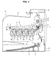
FIG. 1 illustrates an image forming apparatus in accordance with an embodiment of the present disclosure. -
FIG. 2 illustrates a transfer device and a regulation device of an image forming apparatus in accordance with an embodiment of the present disclosure. -
FIG. 3 illustrates a regulation device of an image forming apparatus in accordance with an embodiment of the present disclosure. -
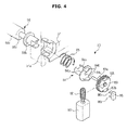
FIG. 4 is an exploded view illustrating a regulation device of an image forming apparatus in accordance with an embodiment of the present disclosure. -
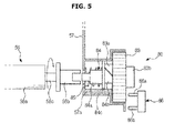
FIG. 5 illustrates an exemplary state before a guide roller is regulated by a regulation device of an image forming apparatus in accordance with an embodiment of the present disclosure. -
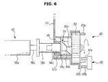
FIG. 6 illustrates an exemplary state of a guide roller regulated by a regulation device of an image forming apparatus in accordance with an embodiment of the present disclosure. - Reference will now be made in detail to the embodiments of the present disclosure, examples of which are illustrated in the accompanying drawings, wherein like reference numerals refer to like elements throughout.
- As illustrated in
FIG. 1 , an image forming apparatus in accordance with an embodiment of the present disclosure includes abody 10 forming an external appearance of the image forming apparatus, a printingmedium storage unit 20 to store printing medium, a plurality of developingunits photoconductors 31 of the charged developingunits transfer device 50 to transfer the visible image formed on thephotoconductors 31 to the printing medium, which is being delivered from the printingmedium storage unit 20, afusing unit 60 to fix the toner, which is transferred to the printing medium, to the printing medium, and a sensing unit 70 to check the toner on atransfer belt 51 of thetransfer device 50. - The
body 10 may be provided at an upper portion thereof with aloading part 10a on which the printing medium completed with the image formation is loaded. A discharge port 10b may be provided at one side of theloading part 10a to allow the printing medium completed with the image formation to be discharged therethrough. An opening 10c may be provided at one side of thebody 10 to allow repair of components or replacement of expendable materials inside thebody 10. A side cover 11 may be included having a lower end rotatably installed at thebody 10 so as to open and close the opening 10c while rotating on the lower end thereof. - The printing
medium storage unit 20 includes aprinting medium cassette 21 movably installed at thebody 10, a knock-upplate 22 to load the printing media while being disposed in theprinting medium cassette 21, and a knock upspring 23 to elastically support the knock-upplate 22. - Each of the developing
units photoconductor 31, on a charged surface of which an electrostatic latent image is formed by the exposure unit 40, a developing roller 32 to supply toner to thephotoconductor 31, and acharging unit 33 to charge the surface of thephotoconductor 31. - The developing
units units units transfer device 50 side by side. - The exposure unit 40 forms the electrostatic latent images on the surfaces of the
photoconductors 31 by irradiating light including image information to thephotoconductors 31 provided at the developingunits - The
transfer device 50 includes atransfer belt 51 on which visible images developed on thephotoconductors 31 of the developingunits roller 52 and a driven roller 53 disposed at opposite sides of inside thetransfer belt 51 to rotate thetransfer belt 51, a plurality offirst transfer rollers 54 disposed opposite to thephotoconductors 31 of the developingunits transfer belt 51 therebetween, such that the visible images formed on thephotoconductors 31 are transferred to thetransfer belt 51, aguide roller 56 disposed on a path between thefirst transfer rollers 54 and the drivingroller 52 and configured to guide a portion of thetransfer belt 51 moving toward the drivingroller 52 by supporting an inner surface of thetransfer belt 51, and atransfer device frame 57 on which both ends of each of thefirst transfer rollers 54, the drivingrollers 52 and the driven rollers 53 are rotatably installed. - A
second transfer roller 55 may be disposed at the side cover opposite to the drivingroller 52 while interposing thetransfer belt 51 therebetween, to press the printing medium toward thetransfer belt 51 to transfer the visible image of thetransfer belt 51 to the printing media. - The fusing
unit 60 includes aheating roller 61 to generate heat, and apressing roller 62, an outer circumferential surface of which is formed of elastically deformable material to press the printing medium onto an outer circumferential surface of theheating roller 61. - At the
body 10, a pick-up roller 12 may be disposed at an upper side of the printingmedium storage unit 20 to pick up the printing media loaded on the knock-upplate 22 one by one, a delivery roller 13 to guide the printing medium, which is picked up by the pick-up roller 12, upward, and adischarge roller 14 disposed at an upper side of the fusingunit 60 while being adjacent to the discharge port 10b to allow the printing medium passing through the fusingunit 60 to be discharged through the discharge port 10b. - The
body 10 may be provided at an inside thereof with frames configured to install and support various elements. The frames include a body frame 15, which may be disposed at a lower portion of an inner side of theopening 10c and on which the sensing unit 70 may be installed. - The sensing unit 70 may be disposed at a lower side of the
transfer belt 51 and installed opposite to a lower surface of thetransfer belt 51 to check the toner on thetransfer belt 51. The sensing unit 70 in accordance with an embodiment of the present disclosure checks a portion of thetransfer belt 51 passing through thefirst transfer rollers 54 and moving toward theguide roller 56. - The
guide roller 56 includes aroller part 56a provided in a cylindrical shape to support the inner surface of thetransfer belt 51, afirst coupling part 56b provided at one side of theroller part 56a so as to be coupled to asecond coupling part 84a of aregulation device 80, and ashaft part 56c connecting theroller part 56a to thefirst coupling part 56b. Theguide roller 56 may be configured to rotate by receiving a force from thetransfer belt 51 through theroller part 56a, which makes contact with the inner surface of thetransfer belt 51, according to the movement of thetransfer belt 51. In a rotation of theguide roller 56, theguide roller 56 is usually vibrated. - The sensing unit 70 may be configured to check a portion of the
transfer belt 51 passing through thefirst transfer rollers 54 and moving toward theguide roller 56. In a case in which theguide roller 56 vibrates while rotating, a portion of thetransfer belt 51 adjacent to the guide roller, that is, the portion of thetransfer belt 51 to be sensed by the sensing unit 70 may be vibrated together with theguide roller 56, and may result in an inaccurate sensing by the sensing unit 70. - As illustrated in
FIGS. 2 and3 , the image forming apparatus includes theregulation device 80 configured to restrict the rotation of theguide roller 56 while the toner on thetransfer belt 51 is being checked by the sensing unit 70. - As illustrated in
FIG. 4 , theregulation device 80 includes a drivingmotor 81 to generate a rotating force, aworm 82 being rotated by the drivingmotor 81, and aworm wheel 83 being rotated according to the rotation of theworm 82 while being teethed with theworm 82. Aregulation member 84 may be installed so as to rotate in a first circumferential direction 100 and configured to restrict the rotation of theguide roller 56 by being coupled to afirst coupling part 56b while rotating in the first circumferential direction 100 according to a rotation of theworm wheel 83. Anelastic member 85 may elastically support theregulation member 84 in a second longitudinal direction 400 opposite to a firstlongitudinal direction 300. Accordingly, theregulation member 84 may be coupled to theguide roller 56 by moving in the firstlongitudinal direction 300 so as to limit the rotation of theguide roller 56, and is separated from theguide roller 56 while moving in a second longitudinal direction 400 opposite to the firstlongitudinal direction 300 so as to allow the rotation of theguide roller 56. - The
worm wheel 83 may be provided at one side surface thereof with afirst cam part 83a having a crest and a trough alternately formed in a circumferential direction of thefirst cam part 83a. Theworm wheel 83 may be provided at the other side surface thereof with a sensedpart 83b that is provided in an arc shape and extends in a circumferential direction of theworm wheel 83. Theregulation device 80 includes aposition detecting sensor 86 including alight emitting part 86a and alight receiving part 86b. The sensedpart 83b in accordance with an embodiment of the present disclosure includes one pair of sensedparts 83b being spaced apart from each other. The sensedparts 83b may be configured to pass through an area between thelight emitting part 86a and thelight receiving part 86b. - Accordingly, in a case in which the sensed
part 83b is disposed at an area between thelight emitting part 86a and thelight receiving part 86b of theposition detecting sensor 86, the sensedpart 83b may be sensed by theposition detecting sensor 86. In a case in which the sensedpart 83b is not in the area between thelight emitting part 86a and thelight receiving part 86b of theposition detecting sensor 86, the sensedpart 83b is not sensed by theposition detecting sensor 86. In this manner, a rotation position of theworm wheel 83 and a position of thefirst cam part 83a provided on theworm wheel 83 may be checked. - The
regulation member 84 may be installed to pass through thetransfer device frame 57 so as to be movable in the first longitudinal direction and the second longitudinal direction. Theregulation member 84 may be provided at one side surface thereof with asecond coupling part 84a engaged with thefirst coupling part 56b of theguide roller 56, and provided at the other side surface thereof with asecond cam part 84b having a crest and a trough alternately formed in a circumferential direction of thesecond cam part 56b so as to correspond to thefirst cam part 83a. In accordance with an embodiment of the present disclosure, each of thefirst cam part 83a and thesecond cam part 84b may have two crests and two troughs in an alternating manner, so that theregulation member 84 moves in the first longitudinal direction according to the interaction between thefirst cam part 83a and thesecond cam part 84b. - The
regulation member 84 includes a lockingpart 84c that is configured to restrict a rotation of theregulation member 84 by being locked with thetransfer device frame 57, and thetransfer device frame 57 includes a lockingprotrusion 57a that is provided at a position corresponding to the lockingpart 84c so as to be locked with the lockingpart 84c. Accordingly, theregulation member 84 is installed at thetransfer device frame 57 so as to be movable in the first and second longitudinal directions while being prevented from rotating, so that the force transmitted to thesecond cam part 84b in a circumferential direction through thefirst cam part 83a is converted to have the first longitudinal direction as an active direction of force, which leads to theregulation member 84 moving in the first longitudinal direction. - The
elastic member 85 has one end supported by thetransfer device frame 57, and the other end supported by the lockingpart 84c of theregulation member 84, thereby elastically supporting theregulation member 84 in the second longitudinal direction. - An exemplary operation of an image forming apparatus in accordance with the present disclosure is described with reference to the accompanied drawings in detail.
- In a state that the toner on the
transfer belt 51 is not checked through the sensing unit 70, as illustrated inFIG. 5 , the crest of thefirst cam part 83a may be inserted into the trough of thesecond cam part 84b, and the crest of thesecond cam part 84b may be inserted into the trough of thefirst cam part 83a. Thus, theregulation member 84 is kept in a state moved in the second longitudinal direction 400, by an elastic restoring force of theelastic member 85. - Accordingly, the
second coupling part 84a is kept in a state of being spaced apart from thefirst coupling part 56b, and theguide roller 56 guides thetransfer belt 51 while rotating according to the movement of thetransfer belt 51. - In a state that the toner on the
transfer belt 51 is checked through the sensing unit 70, as illustrated inFIG. 6 , theworm 82 and theworm wheel 83 are rotated by the drivingmotor 81, and thefirst cam part 83a provided at theworm wheel 83 transmits force to theregulation member 84 through thesecond cam part 84b according to the rotation of theworm wheel 83, and thus theregulation member 84 is moved in the firstlongitudinal direction 300. - In this case, the
worm wheel 83 may be rotated at a predetermined angle at which the crest of thefirst cam part 83a makes contact with the crest of thesecond cam part 84b. The rotation of the predetermined angle may be determined by the sensedpart 83b and theposition detecting sensor 86. - As the
worm wheel 83 rotates at the predetermined angle, theregulation member 84 moves in the first longitudinal direction, and accordingly, thesecond coupling part 84a provided at theregulation member 84 is coupled to thefirst coupling part 56b of theguide roller 56. The lockingpart 84c and the lockingprotrusion 57a prevent theregulation member 84 from rotating, and therefore, in the state of thefirst coupling part 56b coupled to thesecond coupling part 84b, theguide roller 56 is also prevented from rotating and stops rotating. - Accordingly, in a state that the sensing unit 70 checks the toner on the
transfer belt 51, theguide roller 56 does not rotate, so that vibration occurring during a rotation of theguide roller 56 is not generated, thereby precisely and accurately checking the toner on thetransfer belt 51 through the sensing unit 70. - When a toner on the transfer belt is checked through the sensing unit, the guide roller is restricted from rotating by way of a regulation device, so that vibration occurring during a rotation of the guide roller is prevented from exerting influence on checking the toner on the transfer belt, and thus the toner on the transfer belt is precisely and accurately checked.
- Although a few embodiments of the present disclosure have been shown and described, it would be appreciated by those skilled in the art that changes may be made in these embodiments without departing from the principles and spirit of the disclosure, the scope of which is defined in the claims and their equivalents.
- Attention is directed to all papers and documents which are filed concurrently with or previous to this specification in connection with this application and which are open to public inspection with this specification, and the contents of all such papers and documents are incorporated herein by reference.
- All of the features disclosed in this specification (including any accompanying claims, abstract and drawings), and/or all of the steps of any method or process so disclosed, may be combined in any combination, except combinations where at least some of such features and/or steps are mutually exclusive.
- Each feature disclosed in this specification (including any accompanying claims, abstract and drawings) may be replaced by alternative features serving the same, equivalent or similar purpose, unless expressly stated otherwise. Thus, unless expressly stated otherwise, each feature disclosed is one example only of a generic series of equivalent or similar features.
- The invention is not restricted to the details of the foregoing embodiment(s). The invention extends to any novel one, or any novel combination, of the features disclosed in this specification (including any accompanying claims, abstract and drawings), or to any novel one, or any novel combination, of the steps of any method or process so disclosed.
Claims (9)
- An image forming apparatus comprising;
a developing unit configured to develop an electrostatic latent image to a visible image through a toner;
a transfer belt configured to transfer the visible image developed by the developing unit on a printing medium;
a guide roller configured to guide the transfer belt by supporting one side of an inner surface of the transfer belt; and
a regulation device configured to regulate a rotation of the guide roller - The image forming apparatus of claim 1, further comprising:a sensing unit configured to check a toner transferred on the transfer belt,wherein the regulation device restricts the guide roller from rotating when the sensing unit checks the toner transferred on the transfer belt.
- The image forming apparatus of claim 1, wherein the guide roller comprises:a roller part configured to support the inner surface of the transfer belt; anda first coupling part provided at one side of the roller part so as to be connected to the regulation device,wherein the regulation device comprises a regulation member installed so as to be movable in a first longitudinal direction, andthe regulation member is provided at one side surface thereof with a second coupling part engaged with the first coupling part.
- The image forming apparatus of claim 2, wherein the regulation device comprises an elastic member configured to elastically support the regulation member in a second longitudinal direction opposite to the first longitudinal direction.
- The image forming apparatus of clam 2, wherein:the regulation device comprises a driving motor, a worm being rotated by the driving motor, and a worm wheel teethed with the worm;the worm wheel is provided at one side surface thereof with a first cam part having a crest and a trough alternately formed in a circumferential direction of the first cam part; andthe regulation member is provided at an other side surface thereof with a second cam part having a crest and a trough alternately formed in a circumferential direction of the second cam part so as to correspond to the first cam part.
- The image forming apparatus of claim 2, further comprising:a driving roller and a driven roller that are disposed at opposite sides of inside of the transfer belt,wherein the guide roller guides a portion of the transfer belt which moves toward the driving roller, andthe sensing unit checks a portion of the transfer belt which moves toward the guide roller.
- The image forming apparatus of claim 3, further comprising a transfer device frame to which the regulation member is movably installed,
wherein the guide roller comprises a locking part configured to restrict a rotation of the guide roller by being locked with the transfer device frame, and
the transfer device frame comprises a locking protrusion configured to be locked with the locking part. - The image forming apparatus of claim 5, wherein:the worm wheel is provided at other side surface thereof with asensed part extending in a circumferential direction of the worm wheel; andthe regulation device comprises a position detecting sensor to sense the sensed part.
- The image forming apparatus of claim 8, wherein:the position detecting sensor comprises a light emitting part and a light receiving part that are disposed while being spaced apart from each other; andthe sensed part passes through an area between the light emitting part and the light receiving part according to rotation of the worm wheel.
Applications Claiming Priority (1)
| Application Number | Priority Date | Filing Date | Title |
|---|---|---|---|
| KR1020130032128A KR102003423B1 (en) | 2013-03-26 | 2013-03-26 | Image forming apparatus |
Publications (3)
| Publication Number | Publication Date |
|---|---|
| EP2784597A2 true EP2784597A2 (en) | 2014-10-01 |
| EP2784597A3 EP2784597A3 (en) | 2017-09-27 |
| EP2784597B1 EP2784597B1 (en) | 2019-03-06 |
Family
ID=50272518
Family Applications (1)
| Application Number | Title | Priority Date | Filing Date |
|---|---|---|---|
| EP14160033.8A Not-in-force EP2784597B1 (en) | 2013-03-26 | 2014-03-14 | Image forming apparatus |
Country Status (4)
| Country | Link |
|---|---|
| US (1) | US9436146B2 (en) |
| EP (1) | EP2784597B1 (en) |
| KR (1) | KR102003423B1 (en) |
| CN (1) | CN104076642A (en) |
Families Citing this family (2)
| Publication number | Priority date | Publication date | Assignee | Title |
|---|---|---|---|---|
| JP6406272B2 (en) * | 2016-01-28 | 2018-10-17 | 京セラドキュメントソリューションズ株式会社 | Intermediate transfer unit and image forming apparatus |
| JP6957199B2 (en) * | 2017-05-19 | 2021-11-02 | キヤノン株式会社 | Photoreceptor unit |
Family Cites Families (8)
| Publication number | Priority date | Publication date | Assignee | Title |
|---|---|---|---|---|
| JP3462067B2 (en) * | 1998-02-03 | 2003-11-05 | シャープ株式会社 | Image forming device |
| JP5070679B2 (en) * | 2005-03-28 | 2012-11-14 | 富士ゼロックス株式会社 | Image forming apparatus |
| US7657207B2 (en) * | 2006-11-24 | 2010-02-02 | Samsung Electronics Co., Ltd. | Belt driving device, transfer unit using the same and image forming apparatus using the transfer unit |
| CN101303071B (en) * | 2007-05-08 | 2010-08-18 | 京瓷美达株式会社 | Traction-drive type driving-force transmission mechanism and image forming apparatus equipped therewith |
| JP5086042B2 (en) * | 2007-11-30 | 2012-11-28 | 京セラドキュメントソリューションズ株式会社 | Image forming apparatus and image forming process correction control program |
| JP5366783B2 (en) * | 2009-12-15 | 2013-12-11 | キヤノン株式会社 | Image forming apparatus |
| KR20110072252A (en) * | 2009-12-22 | 2011-06-29 | 삼성전자주식회사 | Image forming apparatus and its transfer device |
| JP5699551B2 (en) * | 2010-11-09 | 2015-04-15 | 富士ゼロックス株式会社 | Belt drive device, belt unit and image forming apparatus |
-
2013
- 2013-03-26 KR KR1020130032128A patent/KR102003423B1/en not_active Expired - Fee Related
-
2014
- 2014-03-14 EP EP14160033.8A patent/EP2784597B1/en not_active Not-in-force
- 2014-03-25 CN CN201410113609.XA patent/CN104076642A/en active Pending
- 2014-03-26 US US14/225,986 patent/US9436146B2/en not_active Expired - Fee Related
Also Published As
| Publication number | Publication date |
|---|---|
| US20140294453A1 (en) | 2014-10-02 |
| US9436146B2 (en) | 2016-09-06 |
| EP2784597A3 (en) | 2017-09-27 |
| KR20140117131A (en) | 2014-10-07 |
| KR102003423B1 (en) | 2019-07-24 |
| EP2784597B1 (en) | 2019-03-06 |
| CN104076642A (en) | 2014-10-01 |
Similar Documents
| Publication | Publication Date | Title |
|---|---|---|
| US8755732B2 (en) | Image forming apparatus having a transfer unit for transferring an image to a recording sheet | |
| EP2725430A2 (en) | Image forming apparatus | |
| EP2787392A2 (en) | Image forming apparatus | |
| US8950750B2 (en) | Sheet thickness detector and image forming apparatus including same | |
| US9720361B2 (en) | Belt device, fixing device, and image forming apparatus | |
| US20230090307A1 (en) | Cam driver, transfer device, and image forming apparatus | |
| JP4766140B2 (en) | Deviation correction apparatus, intermediate transfer apparatus, transfer apparatus, and image forming apparatus | |
| US8340564B2 (en) | Sheet thickness detector and image forming apparatus using same | |
| US8783440B2 (en) | Sheet member position correcting device and image forming apparatus | |
| US7801474B2 (en) | Fixing device and image forming apparatus having fixing device | |
| CN104917928B (en) | Image read-out and image forming apparatus | |
| KR101818207B1 (en) | Image forming apparatus | |
| US10747153B2 (en) | Belt-type transport device, fixing device, and image forming apparatus | |
| EP2784597A2 (en) | Image forming apparatus | |
| US20180253037A1 (en) | Image forming apparatus | |
| EP2657778B1 (en) | Image forming apparatus having a cleaning unit to clean an optical sensor unit | |
| JP2018108884A (en) | Paper sheet thickness detection device and image formation device | |
| JP2019105715A (en) | Granular material amount detection mechanism and image forming apparatus including the same |
Legal Events
| Date | Code | Title | Description |
|---|---|---|---|
| 17P | Request for examination filed |
Effective date: 20140314 |
|
| AK | Designated contracting states |
Kind code of ref document: A2 Designated state(s): AL AT BE BG CH CY CZ DE DK EE ES FI FR GB GR HR HU IE IS IT LI LT LU LV MC MK MT NL NO PL PT RO RS SE SI SK SM TR |
|
| AX | Request for extension of the european patent |
Extension state: BA ME |
|
| PUAI | Public reference made under article 153(3) epc to a published international application that has entered the european phase |
Free format text: ORIGINAL CODE: 0009012 |
|
| RAP1 | Party data changed (applicant data changed or rights of an application transferred) |
Owner name: S-PRINTING SOLUTION CO., LTD. |
|
| PUAL | Search report despatched |
Free format text: ORIGINAL CODE: 0009013 |
|
| RIC1 | Information provided on ipc code assigned before grant |
Ipc: F16H 31/00 20060101ALI20170811BHEP Ipc: G03G 15/16 20060101AFI20170811BHEP |
|
| AK | Designated contracting states |
Kind code of ref document: A3 Designated state(s): AL AT BE BG CH CY CZ DE DK EE ES FI FR GB GR HR HU IE IS IT LI LT LU LV MC MK MT NL NO PL PT RO RS SE SI SK SM TR |
|
| AX | Request for extension of the european patent |
Extension state: BA ME |
|
| STAA | Information on the status of an ep patent application or granted ep patent |
Free format text: STATUS: REQUEST FOR EXAMINATION WAS MADE |
|
| R17P | Request for examination filed (corrected) |
Effective date: 20180323 |
|
| RBV | Designated contracting states (corrected) |
Designated state(s): AL AT BE BG CH CY CZ DE DK EE ES FI FR GB GR HR HU IE IS IT LI LT LU LV MC MK MT NL NO PL PT RO RS SE SI SK SM TR |
|
| RAP1 | Party data changed (applicant data changed or rights of an application transferred) |
Owner name: HP PRINTING KOREA CO., LTD. |
|
| STAA | Information on the status of an ep patent application or granted ep patent |
Free format text: STATUS: EXAMINATION IS IN PROGRESS |
|
| 17Q | First examination report despatched |
Effective date: 20180621 |
|
| GRAP | Despatch of communication of intention to grant a patent |
Free format text: ORIGINAL CODE: EPIDOSNIGR1 |
|
| STAA | Information on the status of an ep patent application or granted ep patent |
Free format text: STATUS: GRANT OF PATENT IS INTENDED |
|
| INTG | Intention to grant announced |
Effective date: 20181122 |
|
| GRAS | Grant fee paid |
Free format text: ORIGINAL CODE: EPIDOSNIGR3 |
|
| GRAA | (expected) grant |
Free format text: ORIGINAL CODE: 0009210 |
|
| STAA | Information on the status of an ep patent application or granted ep patent |
Free format text: STATUS: THE PATENT HAS BEEN GRANTED |
|
| AK | Designated contracting states |
Kind code of ref document: B1 Designated state(s): AL AT BE BG CH CY CZ DE DK EE ES FI FR GB GR HR HU IE IS IT LI LT LU LV MC MK MT NL NO PL PT RO RS SE SI SK SM TR |
|
| REG | Reference to a national code |
Ref country code: GB Ref legal event code: FG4D |
|
| REG | Reference to a national code |
Ref country code: CH Ref legal event code: EP Ref country code: AT Ref legal event code: REF Ref document number: 1105351 Country of ref document: AT Kind code of ref document: T Effective date: 20190315 |
|
| REG | Reference to a national code |
Ref country code: DE Ref legal event code: R096 Ref document number: 602014042188 Country of ref document: DE |
|
| REG | Reference to a national code |
Ref country code: IE Ref legal event code: FG4D |
|
| REG | Reference to a national code |
Ref country code: NL Ref legal event code: MP Effective date: 20190306 |
|
| REG | Reference to a national code |
Ref country code: LT Ref legal event code: MG4D |
|
| PG25 | Lapsed in a contracting state [announced via postgrant information from national office to epo] |
Ref country code: FI Free format text: LAPSE BECAUSE OF FAILURE TO SUBMIT A TRANSLATION OF THE DESCRIPTION OR TO PAY THE FEE WITHIN THE PRESCRIBED TIME-LIMIT Effective date: 20190306 Ref country code: LT Free format text: LAPSE BECAUSE OF FAILURE TO SUBMIT A TRANSLATION OF THE DESCRIPTION OR TO PAY THE FEE WITHIN THE PRESCRIBED TIME-LIMIT Effective date: 20190306 Ref country code: SE Free format text: LAPSE BECAUSE OF FAILURE TO SUBMIT A TRANSLATION OF THE DESCRIPTION OR TO PAY THE FEE WITHIN THE PRESCRIBED TIME-LIMIT Effective date: 20190306 Ref country code: NO Free format text: LAPSE BECAUSE OF FAILURE TO SUBMIT A TRANSLATION OF THE DESCRIPTION OR TO PAY THE FEE WITHIN THE PRESCRIBED TIME-LIMIT Effective date: 20190606 |
|
| PG25 | Lapsed in a contracting state [announced via postgrant information from national office to epo] |
Ref country code: NL Free format text: LAPSE BECAUSE OF FAILURE TO SUBMIT A TRANSLATION OF THE DESCRIPTION OR TO PAY THE FEE WITHIN THE PRESCRIBED TIME-LIMIT Effective date: 20190306 Ref country code: RS Free format text: LAPSE BECAUSE OF FAILURE TO SUBMIT A TRANSLATION OF THE DESCRIPTION OR TO PAY THE FEE WITHIN THE PRESCRIBED TIME-LIMIT Effective date: 20190306 Ref country code: HR Free format text: LAPSE BECAUSE OF FAILURE TO SUBMIT A TRANSLATION OF THE DESCRIPTION OR TO PAY THE FEE WITHIN THE PRESCRIBED TIME-LIMIT Effective date: 20190306 Ref country code: GR Free format text: LAPSE BECAUSE OF FAILURE TO SUBMIT A TRANSLATION OF THE DESCRIPTION OR TO PAY THE FEE WITHIN THE PRESCRIBED TIME-LIMIT Effective date: 20190607 Ref country code: LV Free format text: LAPSE BECAUSE OF FAILURE TO SUBMIT A TRANSLATION OF THE DESCRIPTION OR TO PAY THE FEE WITHIN THE PRESCRIBED TIME-LIMIT Effective date: 20190306 Ref country code: BG Free format text: LAPSE BECAUSE OF FAILURE TO SUBMIT A TRANSLATION OF THE DESCRIPTION OR TO PAY THE FEE WITHIN THE PRESCRIBED TIME-LIMIT Effective date: 20190606 |
|
| REG | Reference to a national code |
Ref country code: AT Ref legal event code: MK05 Ref document number: 1105351 Country of ref document: AT Kind code of ref document: T Effective date: 20190306 |
|
| PG25 | Lapsed in a contracting state [announced via postgrant information from national office to epo] |
Ref country code: EE Free format text: LAPSE BECAUSE OF FAILURE TO SUBMIT A TRANSLATION OF THE DESCRIPTION OR TO PAY THE FEE WITHIN THE PRESCRIBED TIME-LIMIT Effective date: 20190306 Ref country code: ES Free format text: LAPSE BECAUSE OF FAILURE TO SUBMIT A TRANSLATION OF THE DESCRIPTION OR TO PAY THE FEE WITHIN THE PRESCRIBED TIME-LIMIT Effective date: 20190306 Ref country code: CZ Free format text: LAPSE BECAUSE OF FAILURE TO SUBMIT A TRANSLATION OF THE DESCRIPTION OR TO PAY THE FEE WITHIN THE PRESCRIBED TIME-LIMIT Effective date: 20190306 Ref country code: AL Free format text: LAPSE BECAUSE OF FAILURE TO SUBMIT A TRANSLATION OF THE DESCRIPTION OR TO PAY THE FEE WITHIN THE PRESCRIBED TIME-LIMIT Effective date: 20190306 Ref country code: RO Free format text: LAPSE BECAUSE OF FAILURE TO SUBMIT A TRANSLATION OF THE DESCRIPTION OR TO PAY THE FEE WITHIN THE PRESCRIBED TIME-LIMIT Effective date: 20190306 Ref country code: PT Free format text: LAPSE BECAUSE OF FAILURE TO SUBMIT A TRANSLATION OF THE DESCRIPTION OR TO PAY THE FEE WITHIN THE PRESCRIBED TIME-LIMIT Effective date: 20190706 Ref country code: SK Free format text: LAPSE BECAUSE OF FAILURE TO SUBMIT A TRANSLATION OF THE DESCRIPTION OR TO PAY THE FEE WITHIN THE PRESCRIBED TIME-LIMIT Effective date: 20190306 Ref country code: IT Free format text: LAPSE BECAUSE OF FAILURE TO SUBMIT A TRANSLATION OF THE DESCRIPTION OR TO PAY THE FEE WITHIN THE PRESCRIBED TIME-LIMIT Effective date: 20190306 |
|
| REG | Reference to a national code |
Ref country code: CH Ref legal event code: PL |
|
| PG25 | Lapsed in a contracting state [announced via postgrant information from national office to epo] |
Ref country code: LU Free format text: LAPSE BECAUSE OF NON-PAYMENT OF DUE FEES Effective date: 20190314 Ref country code: PL Free format text: LAPSE BECAUSE OF FAILURE TO SUBMIT A TRANSLATION OF THE DESCRIPTION OR TO PAY THE FEE WITHIN THE PRESCRIBED TIME-LIMIT Effective date: 20190306 Ref country code: SM Free format text: LAPSE BECAUSE OF FAILURE TO SUBMIT A TRANSLATION OF THE DESCRIPTION OR TO PAY THE FEE WITHIN THE PRESCRIBED TIME-LIMIT Effective date: 20190306 |
|
| REG | Reference to a national code |
Ref country code: BE Ref legal event code: MM Effective date: 20190331 |
|
| REG | Reference to a national code |
Ref country code: DE Ref legal event code: R097 Ref document number: 602014042188 Country of ref document: DE |
|
| REG | Reference to a national code |
Ref country code: DE Ref legal event code: R082 Ref document number: 602014042188 Country of ref document: DE Representative=s name: SCHOPPE, ZIMMERMANN, STOECKELER, ZINKLER, SCHE, DE Ref country code: DE Ref legal event code: R081 Ref document number: 602014042188 Country of ref document: DE Owner name: HEWLETT-PACKARD DEVELOPMENT COMPANY, L.P., SPR, US Free format text: FORMER OWNER: HP PRINTING KOREA CO., LTD., SUWON-SI, GYEONGGI-DO, KR |
|
| PG25 | Lapsed in a contracting state [announced via postgrant information from national office to epo] |
Ref country code: AT Free format text: LAPSE BECAUSE OF FAILURE TO SUBMIT A TRANSLATION OF THE DESCRIPTION OR TO PAY THE FEE WITHIN THE PRESCRIBED TIME-LIMIT Effective date: 20190306 Ref country code: IS Free format text: LAPSE BECAUSE OF FAILURE TO SUBMIT A TRANSLATION OF THE DESCRIPTION OR TO PAY THE FEE WITHIN THE PRESCRIBED TIME-LIMIT Effective date: 20190706 |
|
| PLBE | No opposition filed within time limit |
Free format text: ORIGINAL CODE: 0009261 |
|
| STAA | Information on the status of an ep patent application or granted ep patent |
Free format text: STATUS: NO OPPOSITION FILED WITHIN TIME LIMIT |
|
| PG25 | Lapsed in a contracting state [announced via postgrant information from national office to epo] |
Ref country code: LI Free format text: LAPSE BECAUSE OF NON-PAYMENT OF DUE FEES Effective date: 20190331 Ref country code: DK Free format text: LAPSE BECAUSE OF FAILURE TO SUBMIT A TRANSLATION OF THE DESCRIPTION OR TO PAY THE FEE WITHIN THE PRESCRIBED TIME-LIMIT Effective date: 20190306 Ref country code: CH Free format text: LAPSE BECAUSE OF NON-PAYMENT OF DUE FEES Effective date: 20190331 Ref country code: IE Free format text: LAPSE BECAUSE OF NON-PAYMENT OF DUE FEES Effective date: 20190314 Ref country code: MC Free format text: LAPSE BECAUSE OF FAILURE TO SUBMIT A TRANSLATION OF THE DESCRIPTION OR TO PAY THE FEE WITHIN THE PRESCRIBED TIME-LIMIT Effective date: 20190306 |
|
| 26N | No opposition filed |
Effective date: 20191209 |
|
| PG25 | Lapsed in a contracting state [announced via postgrant information from national office to epo] |
Ref country code: SI Free format text: LAPSE BECAUSE OF FAILURE TO SUBMIT A TRANSLATION OF THE DESCRIPTION OR TO PAY THE FEE WITHIN THE PRESCRIBED TIME-LIMIT Effective date: 20190306 Ref country code: BE Free format text: LAPSE BECAUSE OF NON-PAYMENT OF DUE FEES Effective date: 20190331 |
|
| PG25 | Lapsed in a contracting state [announced via postgrant information from national office to epo] |
Ref country code: TR Free format text: LAPSE BECAUSE OF FAILURE TO SUBMIT A TRANSLATION OF THE DESCRIPTION OR TO PAY THE FEE WITHIN THE PRESCRIBED TIME-LIMIT Effective date: 20190306 |
|
| PG25 | Lapsed in a contracting state [announced via postgrant information from national office to epo] |
Ref country code: MT Free format text: LAPSE BECAUSE OF NON-PAYMENT OF DUE FEES Effective date: 20190314 |
|
| REG | Reference to a national code |
Ref country code: GB Ref legal event code: 732E Free format text: REGISTERED BETWEEN 20200917 AND 20200923 |
|
| PG25 | Lapsed in a contracting state [announced via postgrant information from national office to epo] |
Ref country code: CY Free format text: LAPSE BECAUSE OF FAILURE TO SUBMIT A TRANSLATION OF THE DESCRIPTION OR TO PAY THE FEE WITHIN THE PRESCRIBED TIME-LIMIT Effective date: 20190306 |
|
| PG25 | Lapsed in a contracting state [announced via postgrant information from national office to epo] |
Ref country code: HU Free format text: LAPSE BECAUSE OF FAILURE TO SUBMIT A TRANSLATION OF THE DESCRIPTION OR TO PAY THE FEE WITHIN THE PRESCRIBED TIME-LIMIT; INVALID AB INITIO Effective date: 20140314 |
|
| PGFP | Annual fee paid to national office [announced via postgrant information from national office to epo] |
Ref country code: GB Payment date: 20220225 Year of fee payment: 9 Ref country code: DE Payment date: 20220217 Year of fee payment: 9 |
|
| PGFP | Annual fee paid to national office [announced via postgrant information from national office to epo] |
Ref country code: FR Payment date: 20220221 Year of fee payment: 9 |
|
| PG25 | Lapsed in a contracting state [announced via postgrant information from national office to epo] |
Ref country code: MK Free format text: LAPSE BECAUSE OF FAILURE TO SUBMIT A TRANSLATION OF THE DESCRIPTION OR TO PAY THE FEE WITHIN THE PRESCRIBED TIME-LIMIT Effective date: 20190306 |
|
| REG | Reference to a national code |
Ref country code: DE Ref legal event code: R119 Ref document number: 602014042188 Country of ref document: DE |
|
| GBPC | Gb: european patent ceased through non-payment of renewal fee |
Effective date: 20230314 |
|
| PG25 | Lapsed in a contracting state [announced via postgrant information from national office to epo] |
Ref country code: GB Free format text: LAPSE BECAUSE OF NON-PAYMENT OF DUE FEES Effective date: 20230314 |
|
| PG25 | Lapsed in a contracting state [announced via postgrant information from national office to epo] |
Ref country code: GB Free format text: LAPSE BECAUSE OF NON-PAYMENT OF DUE FEES Effective date: 20230314 Ref country code: FR Free format text: LAPSE BECAUSE OF NON-PAYMENT OF DUE FEES Effective date: 20230331 Ref country code: DE Free format text: LAPSE BECAUSE OF NON-PAYMENT OF DUE FEES Effective date: 20231003 |