EP2784591A2 - Toner collecting device and image forming apparatus including the same - Google Patents
Toner collecting device and image forming apparatus including the same Download PDFInfo
- Publication number
- EP2784591A2 EP2784591A2 EP14160494.2A EP14160494A EP2784591A2 EP 2784591 A2 EP2784591 A2 EP 2784591A2 EP 14160494 A EP14160494 A EP 14160494A EP 2784591 A2 EP2784591 A2 EP 2784591A2
- Authority
- EP
- European Patent Office
- Prior art keywords
- filter
- toner
- air flow
- image forming
- fan
- Prior art date
- Legal status (The legal status is an assumption and is not a legal conclusion. Google has not performed a legal analysis and makes no representation as to the accuracy of the status listed.)
- Withdrawn
Links
- 230000010355 oscillation Effects 0.000 claims abstract description 74
- 238000013459 approach Methods 0.000 claims abstract description 17
- 238000004140 cleaning Methods 0.000 claims description 31
- 230000015572 biosynthetic process Effects 0.000 claims description 19
- 230000002093 peripheral effect Effects 0.000 claims description 16
- 238000011144 upstream manufacturing Methods 0.000 claims description 10
- 238000012546 transfer Methods 0.000 description 33
- 239000011521 glass Substances 0.000 description 22
- 230000001174 ascending effect Effects 0.000 description 18
- 239000003086 colorant Substances 0.000 description 9
- 238000011161 development Methods 0.000 description 9
- 230000005540 biological transmission Effects 0.000 description 5
- 238000010438 heat treatment Methods 0.000 description 5
- 230000006698 induction Effects 0.000 description 4
- 230000000717 retained effect Effects 0.000 description 4
- 230000004308 accommodation Effects 0.000 description 2
- 229910021417 amorphous silicon Inorganic materials 0.000 description 2
- 238000010586 diagram Methods 0.000 description 2
- 239000000428 dust Substances 0.000 description 2
- 239000010419 fine particle Substances 0.000 description 2
- 239000003365 glass fiber Substances 0.000 description 2
- 239000000463 material Substances 0.000 description 2
- 238000000034 method Methods 0.000 description 2
- 230000000630 rising effect Effects 0.000 description 2
- 238000003756 stirring Methods 0.000 description 2
- 238000005513 bias potential Methods 0.000 description 1
- 238000011109 contamination Methods 0.000 description 1
- 230000007547 defect Effects 0.000 description 1
- 239000000835 fiber Substances 0.000 description 1
- 230000004927 fusion Effects 0.000 description 1
- 239000004745 nonwoven fabric Substances 0.000 description 1
- 230000003287 optical effect Effects 0.000 description 1
- 239000000843 powder Substances 0.000 description 1
- 238000012545 processing Methods 0.000 description 1
- 230000035939 shock Effects 0.000 description 1
- 238000004904 shortening Methods 0.000 description 1
Images



Classifications
-
- G—PHYSICS
- G03—PHOTOGRAPHY; CINEMATOGRAPHY; ANALOGOUS TECHNIQUES USING WAVES OTHER THAN OPTICAL WAVES; ELECTROGRAPHY; HOLOGRAPHY
- G03G—ELECTROGRAPHY; ELECTROPHOTOGRAPHY; MAGNETOGRAPHY
- G03G21/00—Arrangements not provided for by groups G03G13/00 - G03G19/00, e.g. cleaning, elimination of residual charge
- G03G21/20—Humidity or temperature control also ozone evacuation; Internal apparatus environment control
- G03G21/206—Conducting air through the machine, e.g. for cooling, filtering, removing gases like ozone
-
- G—PHYSICS
- G03—PHOTOGRAPHY; CINEMATOGRAPHY; ANALOGOUS TECHNIQUES USING WAVES OTHER THAN OPTICAL WAVES; ELECTROGRAPHY; HOLOGRAPHY
- G03G—ELECTROGRAPHY; ELECTROPHOTOGRAPHY; MAGNETOGRAPHY
- G03G15/00—Apparatus for electrographic processes using a charge pattern
- G03G15/06—Apparatus for electrographic processes using a charge pattern for developing
- G03G15/08—Apparatus for electrographic processes using a charge pattern for developing using a solid developer, e.g. powder developer
- G03G15/0896—Arrangements or disposition of the complete developer unit or parts thereof not provided for by groups G03G15/08 - G03G15/0894
- G03G15/0898—Arrangements or disposition of the complete developer unit or parts thereof not provided for by groups G03G15/08 - G03G15/0894 for preventing toner scattering during operation, e.g. seals
-
- G—PHYSICS
- G03—PHOTOGRAPHY; CINEMATOGRAPHY; ANALOGOUS TECHNIQUES USING WAVES OTHER THAN OPTICAL WAVES; ELECTROGRAPHY; HOLOGRAPHY
- G03G—ELECTROGRAPHY; ELECTROPHOTOGRAPHY; MAGNETOGRAPHY
- G03G21/00—Arrangements not provided for by groups G03G13/00 - G03G19/00, e.g. cleaning, elimination of residual charge
- G03G21/10—Collecting or recycling waste developer
- G03G21/105—Arrangements for conveying toner waste
-
- G—PHYSICS
- G03—PHOTOGRAPHY; CINEMATOGRAPHY; ANALOGOUS TECHNIQUES USING WAVES OTHER THAN OPTICAL WAVES; ELECTROGRAPHY; HOLOGRAPHY
- G03G—ELECTROGRAPHY; ELECTROPHOTOGRAPHY; MAGNETOGRAPHY
- G03G21/00—Arrangements not provided for by groups G03G13/00 - G03G19/00, e.g. cleaning, elimination of residual charge
- G03G21/10—Collecting or recycling waste developer
- G03G21/12—Toner waste containers
Definitions
- the present invention relates to a toner collecting device and an image forming apparatus including it.
- Image forming apparatuses employing an electrographic method form a toner image on an image bearing member (e.g., photosensitive drum or transfer belt) in a manner that an electrostatic latent image formed on the image bearing member is developed by supplying toner to the electrostatic latent image.
- the toner is retained in a developing device and is supplied to the image bearing member from a development roller provided in the developing device.
- the toner retained in the developing device less charged toner is liable to fly around the developing device.
- the flying toner may contaminate the inside and outside of an apparatus main body of an image forming apparatus. For this reason, an image forming apparatus is examined on which a dust collecting device for collecting the flying toner is mounted.
- an oscillation section to oscillate the filter is provided.
- a toner collecting device includes a housing, an inlet, a fan, a guide duct portion, a first filter, and an oscillation section.
- the inlet port is provided in the housing. Toner flows into the inlet together with an air flow.
- the fan is arranged in an interior of the housing and is configured to suck the air flow flowing from the inlet and to exhaust the air flow outside the housing.
- the guide duct portion is arranged between the inlet and the fan in a path of the air flow and is configured to guide the air flow upward from below.
- the filter is arranged upstream of the fan in the path of the air flow and in an upper part of the guide duct portion so that its approach surface, which the air flow enters, faces downward.
- the oscillation section is configured to oscillate the first filter.
- An image forming apparatus includes an image bearing member configured to bear a toner image; a developing device configured to supply toner to the image bearing member; the above toner collecting device; and a collection duct configured to collect the toner together with an air flow in an interior of or around the developing device and to allow the toner to flow into the inlet.
- FIG. 1 is a schematic cross sectional view showing an internal configuration of an image forming apparatus 1 according to one embodiment of the present invention.
- a multifunction peripheral having functions of a printer and a copier is exemplified as an image forming apparatus 1 herein.
- the image forming apparatus may be any one of a printer, a copier, and facsimile machine.
- the image forming apparatus 1 includes an apparatus main body 10 and an auto document feeder 20.
- the apparatus main body 10 has a casing configuration substantially in a rectangular parallelepiped shape.
- the auto document feeder 20 is arranged on the apparatus main body 10.
- a reading unit 25 optically reads a to-be-copied document image.
- the image forming section 30 forms a toner image on a sheet.
- the fusing section 60 fuses the toner image to the sheet.
- the paper feeder 40 (sheet accommodation section) stores a sheet to be conveyed to the image forming section 30.
- a sheet is conveyed from the paper feeder 40 or a paper feed tray 46 to a sheet exit port 10E via the image forming section 30 and the fusing section 60.
- the conveyance unit 55 includes in its interior a sheet conveyance path that forms a part of the conveyance path 50.
- the image forming section 30 forms a toner image on a sheet. Specifically, the image forming section 30 generates a full color toner image and transfers the generated toner image to a sheet.
- the image forming section 30 includes an image forming unit 32, an intermediate transfer unit 33, and a toner replenishing section 34.
- the image forming unit 32 includes four units 32Y, 32M, 32C, and 32Bk which are arranged in tandem and form yellow (Y), magenta (M), cyan (C), and black (Bk) toner images, respectively.
- the intermediate transfer unit 33 is arranged on the image forming unit 32 in an adjacent fashion.
- the toner replenishing section 34 is arranged above the intermediate transfer unit 33.
- Each of the image forming units 32Y, 32M, 32C, and 32Bk includes a photosensitive drum 321 (image bearing member), a charger 322, an exposure unit 323, a developing device 324, a primary transfer roller 325, and a cleaner 326.
- the charger 322, the exposure unit 323, the developing device 324, the primary transfer roller 325, and the cleaner 326 are arranged around the corresponding photosensitive drum 321.
- the photosensitive drum 321 rotates about its axis and bears an electrostatic latent image and a toner image on its peripheral surface.
- the photosensitive drum 321 may be a photosensitive drum made from an amorphous silicon (a-Si) based material.
- the charger 322 charges the surface of the photosensitive drum 321 uniformly.
- the exposure unit 323 includes a laser light source and optical systems (mirror, lens, etc.), and forms an electrostatic latent image in a manner that light based on image data of a document image is irradiated to the peripheral surface of the photosensitive drum 321 for exposure.
- the photosensitive drum 321 functions as an image bearing member.
- the developing device 324 supplies toner to the peripheral surface of the photosensitive drum 321 for development of an electrostatic latent image formed on the photosensitive drum 321.
- the developing device 324 may be a developing device for a two-component developer.
- the developing device 324 includes a screw feeder, a magnetic roller, and a development roller. As shown in FIG. 1 , the developing devices 324 for the respective colors are arranged side by side in the horizontal direction (right and left directions).
- the primary transfer roller 325 nips an intermediate transfer belt 331, which is provided in the intermediate transfer unit 33, together with each photosensitive drum 321 to form a nip part, so that toner images on the photosensitive drums 321 are primarily transferred to the intermediate transfer belt 331.
- the cleaner 326 includes a cleaning roller and the like to clean the peripheral surface of the corresponding photosensitive drum 321 after transfer of a toner image.
- the intermediate transfer unit 33 includes the intermediate transfer belt 331, a drive roller 332, and a driven roller 333.
- the intermediate transfer belt 331 is wound between the drive roller 332 and the driven roller 333. Toner images are transferred from the respective photosensitive drums 321 so as to be overlaid with each other at the same location on the outer peripheral surface of the intermediate transfer belt 331.
- the intermediate transfer belt 331 is rotated in the anticlockwise direction in FIG. 1 .
- the intermediate transfer belt 331 functions as an image bearing member.
- a secondary transfer roller 35 (transfer section) is arranged to face the peripheral surface of the drive roller r 332.
- the secondary transfer roller 35 transfers toner images from the intermediate transfer belt 331 to a sheet.
- a nip part between the drive roller drive 332 and the secondary transfer roller 35 serves as a secondary transfer section for transfer of a full color toner image, which is toner mages overlaid on the intermediate transfer belt 331, to a sheet.
- a secondary transfer bias potential having a polarity opposite to that of the toner image is applied to either one of the drive roller 332 and the secondary transfer roller 35, while the other roller is grounded.
- a density sensor 35A is arranged to face the peripheral surface of the intermediate transfer belt 331 on the upstream side of the drive roller 332 in the rotation direction of the intermediate transfer belt 331.
- the density sensor 35A outputs electric signals according to the density of an image formed on the intermediate transfer belt 331.
- the toner replenishing section 34 incudes a yellow tonner container 34Y, a magenta tonner container 34M, a cyan tonner container 34C, and a black tonner container 34Bk.
- the tonner containers 34Y, 34M, 34C, and 34Bk store toner in the respective colors.
- the tonner containers 34Y, 34M, 34C, and 34Bk supply the corresponding color toner through supply paths (not shown) to the developing devices 324 of the image forming units 32Y, 32M, 32C, and 32Bk for the respective colors of Y, M, C, and Bk.
- the paper feeder 40 includes two paper feed cassettes 40A and 40B to accommodate sheets on which image formation is to be performed.
- the paper feed cassettes 40A and 40B are capable of being drawn out frontward from the front of the apparatus main body 10.
- the paper feeder 40 accommodates sheets to be conveyed to the secondary transfer roller 35.
- the paper feeder 40 is arranged below the aforementioned developing devices 324.
- the fusing section 60 is of induction heating type for fusion to fuse a toner image to a sheet.
- the fusing section 60 includes a heating roller 61, a fusing roller 62, a pressure roller 63, a fusing belt 64, and an induction heating unit 65.
- the pressure roller 63 is in press contact with the fusing roller 62 to form a fusing nip part.
- the induction heating unit 65 induction heats the heating roller 61 and the fusing belt 64 so that the heat is applied to the fusing nip part. When a sheet passes through the fusing nip part, the toner image transferred to the sheet is fused to the sheet.
- the image forming apparatus 1 further includes a collection duct 7 and a toner collecting unit (toner collecting device) 8.
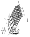
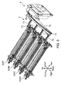
- FIGS. 2 and 3 are perspective views of the developing devices 324, the collection duct 7, and the toner collecting unit 8 according to the present embodiment.
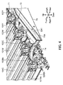
- FIG. 4 is an enlarged perspective view of the developing devices 324 and the collection duct 7 when viewed from the back according to the present embodiment.
- FIGS. 2 and 3 are referred to herein.
- the collection duct 7 is arranged at the rear of the adjacently arranged developing devices 324 (324Y, 324M, 324C, and 324Bk) for the respective colors.
- the collection duct 7 collects toner together with an air flow from the interior of each developing device 324 and allows them to flow into an inlet 800 (see FIG. 5 ) of the toner collecting unit 8.
- the collection duct 7 conveys the toner substantially horizontally from each developing device 324.
- the collection duct 7 may be a duct to collect toner flying around each developing device 324.
- the collection duct 7 includes a main duct 70, a yellow duct 71, a magenta duct 72, a cyan duct 73, and a black duct 74.
- the main duct 70 is a duct extending in the right and left directions at the rear of the developing devices 324.
- a plurality of exhaust paths, to which toner collected from the respective developing devices 324 for the respective colors is conveyed, are arranged in parallel to each other in the interior of the main duct 70 (see exhaust path 70A for black color in FIG. 4 ).
- the yellow duct 71, the magenta duct 72, the cyan duct 73, and the black duct 74 allow the toner collected from the interior of the respective developing devices 324 for the respective colors to flow into the respective exhaust paths of the main duct 70.
- the developing device 324 (324Y, 324M, 324C, and 324Bk) for each color includes a development roller 101 (101Y, 101M, 101C, and 101Bk).
- the development roller 101 bears a toner on its peripheral surface and supplies toner to the corresponding photosensitive drum 321. Further, a screw (not shown) to stir toner and supply the toner to the corresponding development roller 101 is provided in the interior of the developing device 324 for each color.
- the developing device 324 for each color includes an exit port 102 (102Y, 102M, 102C, and 102Bk). The exit port 102 communicates with the interior of the corresponding developing device 324 and opens rearward from the developing device 324.
- the cyan duct 73 is omitted in FIG. 4 to expose the exit port 102C for the cyan color.
- the yellow duct 71, the magenta duct 72, the cyan duct 73, and the black duct 74 are connected so that air flow including flying toner is conveyed from each developing device 324 to the main duct 70.
- the plurality of exhaust paths are arranged in parallel to each other in the interior of the main duct 70.
- the exhaust path 70A for the black color is shown.
- the exhaust paths for the other colors are arranged similarly in the interior of the main duct 70.
- the air flow flowing in the exhaust air path 70A for the black color through the duct 74 for the black color is lead to the left end part of the main duct, as indicated by the arrow D41 in FIG. 4 .
- the toner collecting unit 8 is connected to the left end part of the main duct 70.
- the toner collecting unit 8 is arranged at a lower level than the main duct 70.
- FIG. 5 is a perspective view of the interior of the toner collecting unit 8 according to the present embodiment.
- FIG. 6 is a perspective view of a first filter section 81 according to the present embodiment.
- the toner collecting unit 8 incudes a housing 80, a first filter section 81, a second filter section 82, a first fan 83 (fan), a second fan 84 (fan), and an air exhausting section 85.
- the housing 80 is substantially in a rectangular parallelepiped shape.
- the housing 80 communicates with the developing devices 324 of the image forming section 30 through the collection duct 7.
- the housing 80 defines the outer appearance of the toner collecting unit 8 and accommodates in its interior the first filter section 81, the second filter section 82, the first fan 83, and the second fan 84. Further, a plurality of duct portions to which an air flow is guided are provided in the interior of the housing 80.
- the housing 80 includes an inlet 800, an upper duct 801, a descending duct portion 802 (downward duct portion), an ascending duct portion 80U (upward duct portion), and a bottom portion 80T (reservoir).
- the bottom portion 80T serves as the bottom of the housing 80 and defines the bottom surface of the lower duct 803, which will be described later.
- the inlet 800 opens in the housing 80.
- the inlet 800 communicates with the image forming section 30.
- the toner flows into the inlet 800 together with the air flow.
- the inlet 800 is provided at the upper end part of the housing 80.
- the plurality of exhaust air paths of the main duct 70 are merged immediately before the inlet 800 and continue to the inlet 800.
- the upper duct 801 is a space in the upper end part of the housing 80.
- the upper duct 801 is arranged to face the inlet 800. Further, the upper duct 801 communicates with the descending duct portion 802.
- the descending duct portion 802 communicates with the right end part of the upper duct 801.
- the descending duct portion 802 is arranged to communicate with the inlet 800 through the upper duct 801 in the interior of the housing 80.
- the descending duct portion 802 guides the air flow downward to the bottom portion 80T of the housing 80.
- the descending duct portion 802 serves as a duct portion extending in the vertical direction in the right end part of the housing 80.
- the ascending duct portion 80U is arranged horizontally and adjacently to the descending duct portion 802 in the interior of the housing 80.
- the ascending duct portion 80U communicates with the descending duct portion 802 through the bottom portion 80T to guide the air flow upward.
- the ascending duct portion 80U extends in the vertical direction from the bottom portion 80T to the region where the first fan 83 is arranged.
- the ascending duct portion 80U includes a lower duct 803 (guide duct portion).
- the lower duct 803 is arranged between the inlet 800 and the first and second fans 83 and 84 in the path of the air flow to guide the air flow upward from below.
- the lower duct 803 is arranged at the lower part of the ascending duct portion 80U. Further, as described above, the bottom portion 80T defines the bottom surface of the lower duct 803.
- the descending duct portion 802 communicates with the lower duct 803 of the ascending duct portion 80U through an introduction portion 802T.
- the introduction portion 802T allows the air flow flowing from the inlet 800 to flow into the lower duct 803 from one side (right side) of the lower duct 803.
- the bottom portion 80T is arranged at the lower duct 803 located at a lower level than the introduction portion 802T.
- the first filter section 81 is arrange on the upstream side of the first fan 83 and the second fan 84 in the path of the air flow and in the upper part of the lower duct 803 so that its approach surface, which the air flow enters, faces downward.
- the first filter section 81 catches toner flowing from the inlet 800 together with the air flow and allow the air flow to pass therethrough.
- the first filter section 81 is arranged at the lower part of the ascending duct portion 80U.
- the first filter section 81 is in a rectangular parallelepiped shape with a predetermined width in the vertical direction.
- the second filter section 82 is arranged between the first and second fans 83 and 84 and the first filter section 81 in the path of the air flow.
- the second filter section 82 catches toner that the first filter section 81 cannot have caught and allows the air flow to pass therethrough.
- the second filter section 82 is in a rectangular parallelepiped shape with a predetermined width in the vertical direction.
- the first and second fans 83 and 84 are arranged in the interior of the housing 80 to suck the air flow flowing from the inlet 800 and to exhaust the air outside the housing 80.
- the first and second fans 83 and 84 exhaust the air flow leftward from below.
- the first and second fans 83 and 84 are arranged at the upper part of the ascending duct portion 80U. As shown in FIG. 5 , the first and second fan 83 and 84 are arranged above the second filter section 82 with predetermined intervals apart therefrom.
- the first fan 83 is arranged on the right in the upper end part of the ascending duct portion 80U.
- the second fan 84 is arranged at the location on the left side of the ascending duct portion 80U which is displaced downward from the first fan 83 in the vertical direction.
- a plurality of fans are arranged at the upper part of the ascending duct portion 80U.
- the first and second fans 83 and 84 are arranged so as not to overlap with each other in the vertical direction, so that exhaust paths of the air flow exhausted from the first and second fans 83 and 84 are prevented from overlapping with each other.
- the arrangement of the first and second fans 83 and 84 can result in distribution of the air flow in the vertical direction, thereby efficiently exhausting the air flow leftward.
- the air exhausting section 85 communicates with the ascending duct portion 80U on the downstream side of the first and second fans 83 and 84 in the path of the air flow.
- the air exhausting section 85 guides the air flow in the horizontal direction (leftward) and exhausts it outside the housing 80.
- the air exhausting section 85 is arranged in the region of the left side surface of the housing 80 which ranges from the first filter section 81 to the first fan 83.
- the air exhausting section 85 includes an upper exhaust filter 851 and a lower exhaust filter 852 (third filter).
- the upper exhaust filter 851 and the lower exhaust filter 852 are arranged on the downstream side of the first and second fans 83 and 84 in the path of the air flow to allow the air flow to pass therethrough.
- the upper exhaust filter 851 is arranged to face the first and second fans 83 and 84 in the horizontal direction.
- the lower exhaust filter 852 is arranged below the upper exhaust filter 851.
- the air flow exhausted from the first and second fans 83 and 84 is distributed in the vertical direction in the interior of the air exhausting section 85, passes through the upper and lower exhaust filters 851 and 852, and then is exhausted outside the housing 80.
- the aforementioned first filter section 81 includes a frame 810 (frame body), the first filter 811, and the oscillation motor 812 (oscillation section).
- the frame 810 is supported to the housing 80 and accommodates the first filter 811.
- the frame 810 is arranged to surround the four vertical surfaces (four side surfaces orthogonal to the approach surface) of the first filter 811. Any known fine particle filter may be employed as the first filter 811.
- the first filter 811 in the present embodiment includes filter paper (not shown) with a predetermined density.
- the filter paper is made from glass fiber with a diameter of 1 to 10 ⁇ m.
- the filling rate of the glass fiber is about 10 %.
- the space between fibers is set between 10 and 50 ⁇ m.
- the oscillation motor 812 is fixed at the upper edge of the front wall of the frame 810 and oscillates the first filter 811 through the frame 810.
- the oscillation unit 812 includes an oscillation section 812A.
- the oscillation section 812A incudes an eccentrically arranged anchor on a shaft extending from a motor (not shown). Rotation of the anchor generates oscillation from the oscillation section 812A.
- the first filter 811 is in a rectangular parallelepiped shape having six surfaces as peripheral surfaces including an approach surface (not shown) which the air flow enters and an exhaust surface 811A from which the air flow is exhausted on the opposite side to the approach surface.
- the first filter 811 is arranged in the upper part of the lower duct 803 so that the approach surface faces downward.
- the frame 810 has edges (upper and lower edges of the frame 810) parallel to the approach surface and the exhaust surface 811A of the first filter 811 and includes walls surrounding four surfaces of the six surfaces of the first filter 811, which intersect with the approach surface (and exhaust surface 811A).
- the frame 810 includes a front frame portion 810A, a rear frame portion 810B, a left frame portion 810C, and a right frame portion 810D, each of which is the wall.
- the front frame portion 810A covers the front surface of the first filter 811.
- the rear frame portion 810B covers the rear surface of the first filter 811.
- the left frame portion 810C covers the left surface of the first filter 811.
- the right frame portion 810D covers the right surface of the first filter 811.
- the aforementioned oscillation unit 812 is disposed on a fixed edge 810A1 (edge) at the upper part of the front frame portion 810A.
- the second filter section82 is formed in a manner that the second filter 820 (see FIG. 5 ) is arranged in a frame (not shown). Further, each of the second filter 820, the upper exhaust filter 851, and the lower exhaust filter 852 is a fine particle filter similar to the first filter 811.
- a flow of the air flow and the toner in the toner collecting unit 8 will be described next.
- a controller 95 which will be described later, causes an image forming operation to rotate the development rollers 101 and screws (not shown) of the developing devices 324
- a drive controller 96 which will be described later, causes the first fan 83 and the second fan 84 to rotate.
- the air flow (see arrow D50 in FIG. 5 ) flowing in the housing 80 from the inlet 800 flows into the descending duct portion 802 from the upper duct 801 (arrow D51).
- the air flow once falls down in the descending duct portion 802 (arrow D52) and flows then into the lower duct 803 from the side part of the lower duct 803 through the introduction portion 802T (arrow D53).
- the lower duct 803 guides the air flow upward from below (arrow D54).
- the first filter 811 catches the toner.
- the air flow (arrow D55) having passed through the first filter 811 passes through the second filter 820 of the second filter section 82. In this time, the second filter 820 catches toner not having caught by the first filter 811.
- the first filter section 81 arranged upstream of the first and second fans 83 and 84 catches the toner flowing into the housing 80 together with the air flow.
- the second filter section 82 is arranged upstream of the first and second fans 83 and 84 in the air flow path, and the upper and lower exhaust filters 851 and 852 are arranged downstream of the first and second fans 83 and 84. Accordingly, the toner can be collected reliably, thereby further preventing the toner from being exhausted outside the housing 80. Thus, contamination by flying toner can be favorably prevented inside and outside the image forming apparatus 1.
- A2 ⁇ A1 ⁇ A3 where A1 is a flowing rate of the air flow in the first filter 811 of the first filter section 81, A2 is a flowing rate thereof in the second filter 820 of the second filer portion 82, and A3 is a flowing rate thereof in the upper and lower exhaust filters 851 and 852.
- the air flow toward the first and second fans 83 and 84 can be formed reliably, and the toner can be favorably caught in first and second filters 811 and 820 on the upstream side.
- satisfaction of the relationship can set the flowing rate A3 of the upper and lower exhaust filters 851 and 852 arranged the most downstream in the air flow path to be the smallest.
- the air flow flowing from the inlet 800 can stably pass through the first and second filters 811 and 820. At that time, the first and second filters 811 and 820 can favorably catch the toner.
- the drive controller 96 which will be described later, drives the oscillation motor 812 with timing when the first and second fans 83 and 84 are not rotated.
- the oscillation motor 812 is driven to oscillate the first filter 811 through the frame 810 ( FIG. 6 ). Accordingly, toner adhering especially to the lower surface of the first filter 811 falls down by the oscillation. In this manner, the oscillation of the frame 810 enables reliable transmission of the oscillation to the first filter 811 in the present embodiment.
- the oscillation unit 812 is disposed on the fixed edge 810A1 as the upper edge of the frame 810. Accordingly, vertical oscillation can be stably transmitted to the first filter 811. This can promote toner falling from the first filter 811.
- the first filter 811 is arranged so that its approach surface, which the air flow enters, faces downward. This can prevent falling toner from adhering again to the first filter 811. Accordingly, the first filter 811 can be prevented from being clogged as far as possible, and the toner can be collected stably.
- the introduction portion 802T allows the air flow flowing from the inlet 800 to flow into the lower duct 803 from the side part of the lower duct 803. Then, the toner falling from the first filter 811 by oscillation of the oscillation motor 812 is retained in the bottom portion 80T.
- the bottom portion 80T is arranged in a portion of the lower duct 803 which is located at a lower level than the introduction portion 802T. Accordingly, it can be prevented that the toner retained in the bottom portion 80T disturbs air flow toward the lower duct 803.
- the descending duct portion 802 and the ascending duct portion 80U of the housing 80 are arranged side by side in the horizontal direction in the interior of the housing 80.
- the air flow flowing from the inlet 800 once falls down in the descending duct portion 802 and then rises up in the ascending duct portion 80U. Accordingly, the air flow can become a rising air current reliably.
- the descending duct portion 802 and the ascending duct portion 80U are arranged side by side in the interior of the housing 80, thereby achieving space saving of the housing 80.
- the paper feeder 40 of the image forming apparatus 1 is arranged under the developing devices 324.
- the inlet 800 of the toner collecting unit 8 is formed at substantially the same height in the perpendicular direction as the developing devices 324. Further, the descending duct portion 802 and the ascending duct portion 80U of the toner collection unit 8 face the paper feeder 40 in the horizontal direction. Accordingly, the air flow flowing from the inlet 800 can become a rising air current reliably in the rear of the developing device 324 with the use of the height of the paper feeder 40 of the image forming apparatus 1.
- FIG. 7 is a block diagram showing electrical connection to the controller 95 in the image forming apparatus 1 according to the present embodiment.
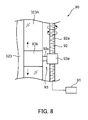
- FIG. 8 is a schematic illustration of a cleaning section 90 of each exposure unit 323 in the image forming apparatus 1 according to the present embodiment.
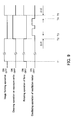
- FIG. 9 is a timing chart depicting operation timing of the oscillation motor 812 in the image forming apparatus 1 according to the present embodiment.
- the controller 95 includes a central processing unit (CPU), a read only memory (ROM) to store a control program, a random access memory (RAM) used as a working area of the CPU, etc. Further, to the controller 95, the image forming section 30 including the aforementioned developing devices 324, the first and second fans 83 and 84, and the oscillation motor 812 are connected electrically. Still more, the cleaning section 90 of each exposure unit 323 is electrically connected to the controller 95. The controller 95 functions as the drive controller 96 by allowing the CPU to execute the control program stored in the ROM.
- CPU central processing unit
- ROM read only memory
- RAM random access memory
- the drive controller 96 controls the drive section (not shown) to dive the respective member of the image forming section 30, the first and second fans 83 and 84, and the oscillation motor 812 with the below mentioned timing. Further, the drive controller 96 drives and rotates a motor 91 of the cleaning section 90, which will be described later, to cause the cleaning section 90 to perform a cleaning operation.
- each exposure unit 323 incudes a transparent glass 323A (transparent member) and the cleaning section 90.
- the transparent glass 323A is a transparent plate member extending in the main scanning direction of the exposure unit 323. Exposure light is emitted from the transparent glass 323A toward the peripheral surface of the corresponding photosensitive drum 321.
- the cleaning section 90 is in contact with the surface of the transparent glass 323A to clean the transparent glass 323A. Accordingly, the exposure light can be prevented from being blocked by toner or dust adhering to the surface of the transparent glass 323A. In particular, the cleaning section 90 cleans the transparent glass 323A in a non-image formation time when the image forming operation is not performed in the image forming section 30.
- the cleaning section 90 includes the motor 91, a screw shaft 92, and a cleaning member 93.
- the motor 91 is connected to the screw shaft 92 to rotate the screw shaft 92 in the normal and reverse directions, as shown in FIG. 8 .
- the screw shaft 92 is connected to the motor 91.
- a male screw 92a is formed around the outer peripheral surface of the screw shaft 92.
- the screw shaft 92 extends in parallel to the transparent glass 323A.
- the cleaning member 93 includes a cylindrical portion 93a, a contact portion 93b, and a connection portion 93c.
- the cylindrical portion 93a is a cylindrical member around the inner peripheral surface of which a female screw (not shown) for engagement with the male screw 92a of the screw shaft 92 is formed.
- the contact portion 93b moves while being in contact with the surface of the transparent glass 323A to wipe off extraneous matter adhering to the surface of the transparent glass 323A, such as toner.
- the contact portion 93b at least a part in contact with the transparent glass 323A is made from a material having high ability to wipe off fine powder of toner and the like, for example, a sponge, a brush, non-woven fabric, etc.
- the connection portion 93c connects the cylindrical portion 93a and the contact portion 93b together.
- the cylindrical portion 93a in engagement with the screw shaft 92 receives a linear drive force from the screw shaft 92.
- This moves the cleaning member 93 in the main scanning direction along the surface of the transparent glass 323A.
- the contact portion 93b moves extraneous matter, such as toner adhering to the surface of the transparent glass 323A outside the opposite ends of the transparent glass 323A in the longitudinal direction (main scanning direction).
- the cleaning member 93 waits at a retreat position outside the transparent glass 323A in the main scanning direction.
- the operation timing is shown in timeline from left to right in FIG. 9 .
- the operation timing is shown for an image forming operation in the image forming section 30, a cleaning operation by the cleaning sections 90 on the exposure units 323, each rotating operation of the first and second fans 83 and 84 of the toner collecting unit 8, and an oscillating operation of the oscillation motor 812 in this order from above.
- an image formation time corresponds to a period from time T1 to T2 and a period of time T5 and thereafter.
- the non-image formation time corresponds to a period from time T2 to time T5.
- the drive controller 96 When the controller 95 causes the image forming section 30 to start performing the image forming operation (time T1) in association with the use of the image forming apparatus 1, the drive controller 96 starts driving the respective members of the image forming section 30. Simultaneously, in the image formation time, the drive controller 96 causes the first and second fans 83 and 84 of the toner collecting unit 8 to rotate. It is noted that the drive controller 96 outputs a rotation start signal and a rotation stop signal for the first and second fans 83 and 84 to control each rotation of the first and second fans 83 and 84. In the image forming operation of the image forming section 30, the development rollers 101 (101Y-101Bk in FIG. 4 ) of the developing devices 324 and the screws (not shown) are rotated.
- toner which is less charged in each developing device 324, stirs up in the interior of the developing device 324.
- the first and second fans 83 and 84 are rotated in the image formation time, as described above. Accordingly, the flying toner can be collected in the toner collecting unit 8 from the developing devices 324 for the respective colors through the collection duct 7.
- the first filter section 81 arranged on the most upstream side in the housing 80 of the toner collecting unit 8 can favorably catch the flying toner.
- the drive controller 96 stops driving each member of the image forming section 30.
- the drive controller 96 outputs the rotation stop signal to each of the first and second fans 83 and 84 to stop each rotation of the first and second fans 83 and 84.
- the drive controller 96 controls the cleaning sections 90 of the exposure units 323 to allow them to start the cleaning operation on the transparent glasses 323A.
- the drive controller 96 controls the oscillation motor 812 to oscillate the first filter 811 of the first filter section 81 in the non-image formation time, in other words, in the cleaning operation by the cleaning sections 90 on the transparent glasses 323A.
- the drive controller 96 outputs the rotation stop signal for the first and second fans 83 and 84 at time T2, and controls then the oscillation motor 812 to oscillate the first filter 811 (time T3) after a predetermined time period ( ⁇ t1) elapses.
- ⁇ t1 is set to be 1 second or longer in the present embodiment. Accordingly, the toner can be stably prevented from adhering again to the first filter 811.
- the drive controller 96 controls oscillation start and stop of the first filter 811 by the oscillation motor 812 twice (plural times) in succession in the non-image formation time. Accordingly, shock at oscillation start of the first filter 811 by the oscillation motor 812 is caused plural times. Accordingly, effective falling of the toner from the first filter 811 can be caused. It is noted that oscillation start and stop of the first filter 811 may be performed three or more times in succession.
- the drive controller 96 stops the oscillation motor 812 at time T4.
- the drive controller 96 stops oscillation of the first filter 811 by the oscillation motor 812 (time T4) a predetermined time period ( ⁇ t2) before the time T5 when the drive controller 96 outputs the rotation start signal for the first and second fans 83 and 84 for the next image forming operation.
- ⁇ t2 is set to be 1 second or longer in the present embodiment. Accordingly, rotation start of the first and second fans 83 and 84 in the state where the toner flies can be further stably prevented.
- the drive controller 96 causes the first and second fans 83 and 84 to rotate in the image formation time to collect unnecessary toner from the image forming section 30.
- the drive controller 96 controls the oscillation motor 812 to oscillate the first filter 811 in the non-image formation time of the image forming section 30. Accordingly, toner falling from the first filter 811 can be prevented from adhering again to the first filter 811, which may be caused by air suction by the first and second fans 83 and 84, as far as possible.
- the first filter 811 is oscillated in cleaning the transparent glasses 323A by the cleaning sections 90. Accordingly, the cleaning operation on the transparent glasses 323A and the cleaning operation on the first filter 811 can be performed in parallel in the image forming apparatus 1, thereby shortening the period of the non-image formation time.
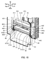
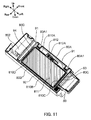
- FIGS. 10 and 11 are referred herein.
- FIGS. 10 and 11 are cross sectional perspective view of the interior of the toner collecting unit 8.
- the toner collecting unit 8 collects unnecessary toner from the image forming section 30. In the present embodiment, as described above, flying toner is collected as the unnecessary toner from the developing devices 324.
- the housing 80 includes eight (six types of) support walls arranged to face the respective six surfaces of the first filter 811. Specifically, the housing 80 includes a front wall 80A (first support wall), a rear wall 80B (second support wall), a left wall 80C (third support wall), and a right inner wall 80D (fourth support wall).
- the housing 80 further incudes an upper left rib 80E (fifth support wall), a lower left rib 80F (sixth support wall), an upper right rib 80G (fifth support wall), and a lower right rib 80H (sixth support wall).
- the front wall 80A is arranged to face the front side surface of the first filter 811.
- the front frame portion 810A of the frame 810 is arranged between the front side surface of the first filter 811 and the front wall 80A.
- the front wall 80A includes a pair of protruding walls 80A1.
- the protruding walls 80A1 are formed in a fashion that the right and left end parts of the front wall 80A partially protrude toward the front frame portion 810A.
- the rear wall 80B is arranged to face the rear side surface of the first filter 811.
- the rear frame portion 810B of the frame 810 is arranged between the rear side surface of the first filter 811 and the rear wall 810B.
- the left wall 80C is arranged to face the left side surface of the first filter 811.
- the left frame portion 810C of the frame 810 is arranged between the left side surface of the first filter 811 and the left wall 80C.
- the right inner wall 80D is arranged to face the right side surface of the first filter 811.
- the right frame portion 810D of the frame 810 is arranged between the right side surface of the first filter 811 and the right inner wall 80D.
- the aforementioned descending duct portion 802 is arranged on the right side of the right inner wall 80D.
- the upper left rib 80E is arranged to face the exhaust surface 811A of the first filter 811 above the left frame portion 810C. In other words, the upper left rib 80E is arranged to face the upper edge of the left frame portion 810C.
- the upper left rib 80E is a rib member protruding rightward from the left wall 80C.
- the lower left rib 80F is arranged to face the approach surface (not shown) of the first filter 811 below the left frame portion 810C.
- the lower left rib 80F is arranged to face a left bent portion 810C1 which is a rightwardly bent lower end part of the left frame portion 810C.
- the left bent portion 810C1 can prevent the first filter 811 from falling down from the frame 810.
- the lower left rib 80F is a rib member protruding rightward from the left wall 80C.
- the upper right rib 80G is arranged to face the exhaust surface 811A of the first filter 811 above the right frame portion 810D.
- the upper right rib 80G is arranged to face the upper edge of the right frame portion 810D.
- the upper right rib 80G is a rib member protruding leftward from the right inner wall 80D.
- the lower right rib 80H is arranged to face the approach surface (not shown) of the first filter 811 below the right frame portion 810D.
- a lower right rib 80H is arranged to face a right bent portion 810D1 which is a lefwardly bent lower edge of the right frame portion 810D.
- the right bent portion 810D1 also can prevent the first filter 811 from falling down from the frame 810.
- the lower right rib 80H is a rib member protruding leftward from the right inner wall 80D.
- the toner collecting unit 8 includes front sponges 91, a rear sponge 92, a left sponge 93, a right sponge 94, an upper left sponge 95, a lower left sponge 96, an upper right sponge 97, and a lower right sponge 98 (each being an elastic member).
- the sponges are compressed between the frame 810 and the housing 80 to prevent transmission of oscillation from the frame 810 to the housing 80.
- the front sponges 91 are arranged in pair between the front frame portion 810A and the pair of protruding walls 80A1.
- the rear sponge 92 is arranged between the rear frame portion 810B and the rear wall 80B.
- the left sponge 93 is arranged between the left frame portion 810C and the left wall 80C.
- the right sponge 94 is arranged between the right frame portion 810D and the right wall 80D.
- the upper left sponge 95 is arranged between the upper edge of the left frame portion 810C and the upper left rib 80E.
- the lower left sponge 96 is arranged between the left bent portion 810C1 of the left frame portion 810C and the lower left rib 80F.
- the upper right sponge 97 is arranged between the upper edge of the right frame portion 810D and the upper right rib 80G.
- the lower right sponge 98 is arranged between the right bent portion 810D1 of the right frame portion 810D and the lower right rib 80H.
- the upper left sponge 95 and the upper right sponge 97 may be in contact with the edge 810A2 of the front frame portion 810A.
- the above sponges are arranged in this fashion between the respective six support walls arranged to face the respective six surfaces of the first filter 811 and the frame 810 in the present embodiment.
- the sponges are arranged between the frame 810 and the housing 80 in the present embodiment.
- This can prevent oscillation of the first filter 811 by the oscillation unit 812 from being transmitted to the housing 80. Accordingly, oscillation noise by oscillation of the housing 80 can be prevented from being caused.
- the front sponges 91, the rear sponge 92, the left sponge 93, the right sponge 94, the upper left sponge 95, the lower left sponge 96, the upper right sponge 97, and the lower right sponge 98 can prevent transmission of oscillation from the respective six surfaces of the first filter 811 to the housing 80. In other words, transmission of oscillation in the vertical direction, the back-and-forth directions, and the right and left directions can be reduced. This can reliably reduce oscillation noise by oscillation of the housing 80.
- the oscillation unit 812 is mounted directly on the frame 810 rather than the housing 80, which can further reduce transmission of oscillation.
- the toner collecting unit 8 and the image forming apparatus 1 including it according to the present embodiment have been described so far.
- the present invention is not limited to them and can be modified to any of the following variations, for example.
Landscapes
- Physics & Mathematics (AREA)
- General Physics & Mathematics (AREA)
- Life Sciences & Earth Sciences (AREA)
- Engineering & Computer Science (AREA)
- Environmental & Geological Engineering (AREA)
- Sustainable Development (AREA)
- Atmospheric Sciences (AREA)
- Biodiversity & Conservation Biology (AREA)
- Ecology (AREA)
- Environmental Sciences (AREA)
- Control Or Security For Electrophotography (AREA)
- Dry Development In Electrophotography (AREA)
- Cleaning In Electrography (AREA)
Abstract
Description
- The present invention relates to a toner collecting device and an image forming apparatus including it.
- Image forming apparatuses employing an electrographic method (e.g., copiers, printers, and facsimile machines) form a toner image on an image bearing member (e.g., photosensitive drum or transfer belt) in a manner that an electrostatic latent image formed on the image bearing member is developed by supplying toner to the electrostatic latent image. The toner is retained in a developing device and is supplied to the image bearing member from a development roller provided in the developing device.
- Of the toner retained in the developing device, less charged toner is liable to fly around the developing device. The flying toner may contaminate the inside and outside of an apparatus main body of an image forming apparatus. For this reason, an image forming apparatus is examined on which a dust collecting device for collecting the flying toner is mounted. In this technique, in order to prevent a filter from clogging with the flying toner, an oscillation section to oscillate the filter is provided.
- A toner collecting device according to one mode of the present invention includes a housing, an inlet, a fan, a guide duct portion, a first filter, and an oscillation section. The inlet port is provided in the housing. Toner flows into the inlet together with an air flow. The fan is arranged in an interior of the housing and is configured to suck the air flow flowing from the inlet and to exhaust the air flow outside the housing. The guide duct portion is arranged between the inlet and the fan in a path of the air flow and is configured to guide the air flow upward from below. The filter is arranged upstream of the fan in the path of the air flow and in an upper part of the guide duct portion so that its approach surface, which the air flow enters, faces downward. The oscillation section is configured to oscillate the first filter.
- An image forming apparatus according to another mode of the present invention includes an image bearing member configured to bear a toner image; a developing device configured to supply toner to the image bearing member; the above toner collecting device; and a collection duct configured to collect the toner together with an air flow in an interior of or around the developing device and to allow the toner to flow into the inlet.
-
-
FIG. 1 is a schematic cross sectional view showing an internal configuration of an image forming apparatus according to one embodiment of the present invention. -
FIG. 2 is a perspective view of a developing device and a toner collecting device in the image forming apparatus according to one embodiment of the present invention. -
FIG. 3 is a perspective view of the developing device and the toner collecting device in the image forming apparatus according to one embodiment of the present invention. -
FIG. 4 is an enlarged perspective view of the developing device and a collection duct in the image forming apparatus according to one embodiment of the present invention. -
FIG. 5 is a perspective view of the interior of a toner collecting unit (toner collecting device) according to one embodiment of the present invention. -
FIG. 6 is a perspective view of a first filter in the toner collection device according to one embodiment of the present invention. -
FIG. 7 is an electrical block diagram of the image forming apparatus according to one embodiment of the present invention. -
FIG. 8 is a schematic view of a cleaning section of an exposure device in the image forming apparatus according to one embodiment of the present invention. -
FIG. 9 is a timing chart depicting operation timing of an oscillation section in the image forming apparatus according to one embodiment of the present invention. -
FIG. 10 is a cross sectional perspective view of the interior of the toner collecting unit according to one embodiment of the present invention. -
FIG. 11 is a cross sectional perspective view of the interior of the toner collecting unit according to one embodiment of the present invention. - Embodiments of the present invention will be described in detail below with reference to the accompanying drawings.
FIG. 1 is a schematic cross sectional view showing an internal configuration of animage forming apparatus 1 according to one embodiment of the present invention. A multifunction peripheral having functions of a printer and a copier is exemplified as animage forming apparatus 1 herein. However, the image forming apparatus may be any one of a printer, a copier, and facsimile machine. - The
image forming apparatus 1 includes an apparatusmain body 10 and anauto document feeder 20. The apparatusmain body 10 has a casing configuration substantially in a rectangular parallelepiped shape. Theauto document feeder 20 is arranged on the apparatusmain body 10. In the interior of the apparatusmain body 10, areading unit 25, animage forming section 30, afusing section 60, a paper feeder 40 (sheet accommodation section), aconveyance path 50, and aconveyance unit 55 are accommodated. Thereading unit 25 optically reads a to-be-copied document image. Theimage forming section 30 forms a toner image on a sheet. Thefusing section 60 fuses the toner image to the sheet. The paper feeder 40 (sheet accommodation section) stores a sheet to be conveyed to theimage forming section 30. In theconveyance path 50, a sheet is conveyed from the paper feeder 40 or apaper feed tray 46 to asheet exit port 10E via theimage forming section 30 and thefusing section 60. Theconveyance unit 55 includes in its interior a sheet conveyance path that forms a part of theconveyance path 50. - The
image forming section 30 forms a toner image on a sheet. Specifically, theimage forming section 30 generates a full color toner image and transfers the generated toner image to a sheet. Theimage forming section 30 includes animage forming unit 32, anintermediate transfer unit 33, and a toner replenishingsection 34. Theimage forming unit 32 includes fourunits intermediate transfer unit 33 is arranged on theimage forming unit 32 in an adjacent fashion. The toner replenishingsection 34 is arranged above theintermediate transfer unit 33. - Each of the
image forming units charger 322, anexposure unit 323, a developingdevice 324, aprimary transfer roller 325, and acleaner 326. Thecharger 322, theexposure unit 323, the developingdevice 324, theprimary transfer roller 325, and thecleaner 326 are arranged around the correspondingphotosensitive drum 321. - The
photosensitive drum 321 rotates about its axis and bears an electrostatic latent image and a toner image on its peripheral surface. One example of thephotosensitive drum 321 may be a photosensitive drum made from an amorphous silicon (a-Si) based material. Thecharger 322 charges the surface of thephotosensitive drum 321 uniformly. Theexposure unit 323 includes a laser light source and optical systems (mirror, lens, etc.), and forms an electrostatic latent image in a manner that light based on image data of a document image is irradiated to the peripheral surface of thephotosensitive drum 321 for exposure. Thephotosensitive drum 321 functions as an image bearing member. - The developing
device 324 supplies toner to the peripheral surface of thephotosensitive drum 321 for development of an electrostatic latent image formed on thephotosensitive drum 321. In one example, the developingdevice 324 may be a developing device for a two-component developer. The developingdevice 324 includes a screw feeder, a magnetic roller, and a development roller. As shown inFIG. 1 , the developingdevices 324 for the respective colors are arranged side by side in the horizontal direction (right and left directions). - The
primary transfer roller 325 nips anintermediate transfer belt 331, which is provided in theintermediate transfer unit 33, together with eachphotosensitive drum 321 to form a nip part, so that toner images on thephotosensitive drums 321 are primarily transferred to theintermediate transfer belt 331. Thecleaner 326 includes a cleaning roller and the like to clean the peripheral surface of the correspondingphotosensitive drum 321 after transfer of a toner image. - The
intermediate transfer unit 33 includes theintermediate transfer belt 331, adrive roller 332, and a driven roller 333. Theintermediate transfer belt 331 is wound between thedrive roller 332 and the driven roller 333. Toner images are transferred from the respectivephotosensitive drums 321 so as to be overlaid with each other at the same location on the outer peripheral surface of theintermediate transfer belt 331. Theintermediate transfer belt 331 is rotated in the anticlockwise direction inFIG. 1 . Theintermediate transfer belt 331 functions as an image bearing member. - A secondary transfer roller 35 (transfer section) is arranged to face the peripheral surface of the
drive roller r 332. Thesecondary transfer roller 35 transfers toner images from theintermediate transfer belt 331 to a sheet. A nip part between thedrive roller drive 332 and thesecondary transfer roller 35 serves as a secondary transfer section for transfer of a full color toner image, which is toner mages overlaid on theintermediate transfer belt 331, to a sheet. A secondary transfer bias potential having a polarity opposite to that of the toner image is applied to either one of thedrive roller 332 and thesecondary transfer roller 35, while the other roller is grounded. Further, adensity sensor 35A is arranged to face the peripheral surface of theintermediate transfer belt 331 on the upstream side of thedrive roller 332 in the rotation direction of theintermediate transfer belt 331. Thedensity sensor 35A outputs electric signals according to the density of an image formed on theintermediate transfer belt 331. - The
toner replenishing section 34 incudes a yellow tonner container 34Y, amagenta tonner container 34M, acyan tonner container 34C, and a black tonner container 34Bk. Thetonner containers tonner containers devices 324 of theimage forming units - The paper feeder 40 includes two
paper feed cassettes paper feed cassettes main body 10. The paper feeder 40 accommodates sheets to be conveyed to thesecondary transfer roller 35. The paper feeder 40 is arranged below the aforementioned developingdevices 324. - Herein, the fusing
section 60 is of induction heating type for fusion to fuse a toner image to a sheet. The fusingsection 60 includes aheating roller 61, a fusing roller 62, apressure roller 63, a fusingbelt 64, and aninduction heating unit 65. Thepressure roller 63 is in press contact with the fusing roller 62 to form a fusing nip part. Theinduction heating unit 65 induction heats theheating roller 61 and the fusingbelt 64 so that the heat is applied to the fusing nip part. When a sheet passes through the fusing nip part, the toner image transferred to the sheet is fused to the sheet. - The
image forming apparatus 1 further includes acollection duct 7 and a toner collecting unit (toner collecting device) 8.FIGS. 2 and3 are perspective views of the developingdevices 324, thecollection duct 7, and thetoner collecting unit 8 according to the present embodiment.FIG. 4 is an enlarged perspective view of the developingdevices 324 and thecollection duct 7 when viewed from the back according to the present embodiment. -
FIGS. 2 and3 are referred to herein. Thecollection duct 7 is arranged at the rear of the adjacently arranged developing devices 324 (324Y, 324M, 324C, and 324Bk) for the respective colors. Thecollection duct 7 collects toner together with an air flow from the interior of each developingdevice 324 and allows them to flow into an inlet 800 (seeFIG. 5 ) of thetoner collecting unit 8. As shown inFIG. 2 , thecollection duct 7 conveys the toner substantially horizontally from each developingdevice 324. It is noted that in another embodiment, thecollection duct 7 may be a duct to collect toner flying around each developingdevice 324. Thecollection duct 7 includes amain duct 70, ayellow duct 71, amagenta duct 72, acyan duct 73, and ablack duct 74. Themain duct 70 is a duct extending in the right and left directions at the rear of the developingdevices 324. A plurality of exhaust paths, to which toner collected from the respective developingdevices 324 for the respective colors is conveyed, are arranged in parallel to each other in the interior of the main duct 70 (seeexhaust path 70A for black color inFIG. 4 ). Theyellow duct 71, themagenta duct 72, thecyan duct 73, and theblack duct 74 allow the toner collected from the interior of the respective developingdevices 324 for the respective colors to flow into the respective exhaust paths of themain duct 70. -
FIG. 4 is referred to herein. The developing device 324 (324Y, 324M, 324C, and 324Bk) for each color includes a development roller 101 (101Y, 101M, 101C, and 101Bk). The development roller 101 bears a toner on its peripheral surface and supplies toner to the correspondingphotosensitive drum 321. Further, a screw (not shown) to stir toner and supply the toner to the corresponding development roller 101 is provided in the interior of the developingdevice 324 for each color. The developingdevice 324 for each color includes an exit port 102 (102Y, 102M, 102C, and 102Bk). The exit port 102 communicates with the interior of the corresponding developingdevice 324 and opens rearward from the developingdevice 324. For the sake of easy understanding of the configuration, thecyan duct 73 is omitted inFIG. 4 to expose theexit port 102C for the cyan color. To the exit ports 102 for the respective colors, theyellow duct 71, themagenta duct 72, thecyan duct 73, and theblack duct 74 are connected so that air flow including flying toner is conveyed from each developingdevice 324 to themain duct 70. As described above, the plurality of exhaust paths are arranged in parallel to each other in the interior of themain duct 70. InFIG. 4 , theexhaust path 70A for the black color is shown. The exhaust paths for the other colors are arranged similarly in the interior of themain duct 70. The air flow flowing in theexhaust air path 70A for the black color through theduct 74 for the black color is lead to the left end part of the main duct, as indicated by the arrow D41 inFIG. 4 . - The
toner collecting unit 8 is connected to the left end part of themain duct 70. Thetoner collecting unit 8 is arranged at a lower level than themain duct 70. - With reference to
FIGS. 5 and6 , the configuration of thetoner collecting unit 8 according to the present embodiment will be described next.FIG. 5 is a perspective view of the interior of thetoner collecting unit 8 according to the present embodiment.FIG. 6 is a perspective view of afirst filter section 81 according to the present embodiment. - As shown in
FIG. 5 , thetoner collecting unit 8 incudes ahousing 80, afirst filter section 81, asecond filter section 82, a first fan 83 (fan), a second fan 84 (fan), and anair exhausting section 85. - The
housing 80 is substantially in a rectangular parallelepiped shape. Thehousing 80 communicates with the developingdevices 324 of theimage forming section 30 through thecollection duct 7. Thehousing 80 defines the outer appearance of thetoner collecting unit 8 and accommodates in its interior thefirst filter section 81, thesecond filter section 82, thefirst fan 83, and thesecond fan 84. Further, a plurality of duct portions to which an air flow is guided are provided in the interior of thehousing 80. Thehousing 80 includes aninlet 800, anupper duct 801, a descending duct portion 802 (downward duct portion), an ascendingduct portion 80U (upward duct portion), and abottom portion 80T (reservoir). Thebottom portion 80T serves as the bottom of thehousing 80 and defines the bottom surface of thelower duct 803, which will be described later. - The
inlet 800 opens in thehousing 80. Theinlet 800 communicates with theimage forming section 30. The toner flows into theinlet 800 together with the air flow. Theinlet 800 is provided at the upper end part of thehousing 80. The plurality of exhaust air paths of themain duct 70 are merged immediately before theinlet 800 and continue to theinlet 800. - The
upper duct 801 is a space in the upper end part of thehousing 80. Theupper duct 801 is arranged to face theinlet 800. Further, theupper duct 801 communicates with the descendingduct portion 802. - Further, the descending
duct portion 802 communicates with the right end part of theupper duct 801. In other words, the descendingduct portion 802 is arranged to communicate with theinlet 800 through theupper duct 801 in the interior of thehousing 80. The descendingduct portion 802 guides the air flow downward to thebottom portion 80T of thehousing 80. The descendingduct portion 802 serves as a duct portion extending in the vertical direction in the right end part of thehousing 80. - The ascending
duct portion 80U is arranged horizontally and adjacently to the descendingduct portion 802 in the interior of thehousing 80. The ascendingduct portion 80U communicates with the descendingduct portion 802 through thebottom portion 80T to guide the air flow upward. The ascendingduct portion 80U extends in the vertical direction from thebottom portion 80T to the region where thefirst fan 83 is arranged. The ascendingduct portion 80U includes a lower duct 803 (guide duct portion). Thelower duct 803 is arranged between theinlet 800 and the first andsecond fans lower duct 803 is arranged at the lower part of the ascendingduct portion 80U. Further, as described above, thebottom portion 80T defines the bottom surface of thelower duct 803. - The descending
duct portion 802 communicates with thelower duct 803 of the ascendingduct portion 80U through anintroduction portion 802T. In other words, theintroduction portion 802T allows the air flow flowing from theinlet 800 to flow into thelower duct 803 from one side (right side) of thelower duct 803. Thebottom portion 80T is arranged at thelower duct 803 located at a lower level than theintroduction portion 802T. - The
first filter section 81 is arrange on the upstream side of thefirst fan 83 and thesecond fan 84 in the path of the air flow and in the upper part of thelower duct 803 so that its approach surface, which the air flow enters, faces downward. Thefirst filter section 81 catches toner flowing from theinlet 800 together with the air flow and allow the air flow to pass therethrough. Thefirst filter section 81 is arranged at the lower part of the ascendingduct portion 80U. Thefirst filter section 81 is in a rectangular parallelepiped shape with a predetermined width in the vertical direction. - The
second filter section 82 is arranged between the first andsecond fans first filter section 81 in the path of the air flow. Thesecond filter section 82 catches toner that thefirst filter section 81 cannot have caught and allows the air flow to pass therethrough. Thesecond filter section 82 is in a rectangular parallelepiped shape with a predetermined width in the vertical direction. - The first and
second fans housing 80 to suck the air flow flowing from theinlet 800 and to exhaust the air outside thehousing 80. The first andsecond fans second fans duct portion 80U. As shown inFIG. 5 , the first andsecond fan second filter section 82 with predetermined intervals apart therefrom. Thefirst fan 83 is arranged on the right in the upper end part of the ascendingduct portion 80U. By contrast, thesecond fan 84 is arranged at the location on the left side of the ascendingduct portion 80U which is displaced downward from thefirst fan 83 in the vertical direction. As such, in the present embodiment, a plurality of fans are arranged at the upper part of the ascendingduct portion 80U. Further, the first andsecond fans second fans second fans - The
air exhausting section 85 communicates with the ascendingduct portion 80U on the downstream side of the first andsecond fans air exhausting section 85 guides the air flow in the horizontal direction (leftward) and exhausts it outside thehousing 80. As shown inFIG. 5 , theair exhausting section 85 is arranged in the region of the left side surface of thehousing 80 which ranges from thefirst filter section 81 to thefirst fan 83. - The
air exhausting section 85 includes anupper exhaust filter 851 and a lower exhaust filter 852 (third filter). Theupper exhaust filter 851 and thelower exhaust filter 852 are arranged on the downstream side of the first andsecond fans upper exhaust filter 851 is arranged to face the first andsecond fans lower exhaust filter 852 is arranged below theupper exhaust filter 851. The air flow exhausted from the first andsecond fans air exhausting section 85, passes through the upper andlower exhaust filters housing 80. - As shown in
FIG. 6 , the aforementionedfirst filter section 81 includes a frame 810 (frame body), thefirst filter 811, and the oscillation motor 812 (oscillation section). Theframe 810 is supported to thehousing 80 and accommodates thefirst filter 811. Theframe 810 is arranged to surround the four vertical surfaces (four side surfaces orthogonal to the approach surface) of thefirst filter 811. Any known fine particle filter may be employed as thefirst filter 811. Thefirst filter 811 in the present embodiment includes filter paper (not shown) with a predetermined density. The filter paper is made from glass fiber with a diameter of 1 to 10 µm. The filling rate of the glass fiber is about 10 %. The space between fibers is set between 10 and 50 µm. Theoscillation motor 812 is fixed at the upper edge of the front wall of theframe 810 and oscillates thefirst filter 811 through theframe 810. Theoscillation unit 812 includes anoscillation section 812A. Theoscillation section 812A incudes an eccentrically arranged anchor on a shaft extending from a motor (not shown). Rotation of the anchor generates oscillation from theoscillation section 812A. - The
first filter 811 is in a rectangular parallelepiped shape having six surfaces as peripheral surfaces including an approach surface (not shown) which the air flow enters and anexhaust surface 811A from which the air flow is exhausted on the opposite side to the approach surface. Thefirst filter 811 is arranged in the upper part of thelower duct 803 so that the approach surface faces downward. - The
frame 810 has edges (upper and lower edges of the frame 810) parallel to the approach surface and theexhaust surface 811A of thefirst filter 811 and includes walls surrounding four surfaces of the six surfaces of thefirst filter 811, which intersect with the approach surface (andexhaust surface 811A). Specifically, theframe 810 includes afront frame portion 810A, arear frame portion 810B, aleft frame portion 810C, and aright frame portion 810D, each of which is the wall. Thefront frame portion 810A covers the front surface of thefirst filter 811. Therear frame portion 810B covers the rear surface of thefirst filter 811. Theleft frame portion 810C covers the left surface of thefirst filter 811. Theright frame portion 810D covers the right surface of thefirst filter 811. Theaforementioned oscillation unit 812 is disposed on a fixed edge 810A1 (edge) at the upper part of thefront frame portion 810A. - Similarly to the
first filter section 81, the second filter section82 is formed in a manner that the second filter 820 (seeFIG. 5 ) is arranged in a frame (not shown). Further, each of thesecond filter 820, theupper exhaust filter 851, and thelower exhaust filter 852 is a fine particle filter similar to thefirst filter 811. - A flow of the air flow and the toner in the
toner collecting unit 8 will be described next. When the power source of theimage forming apparatus 1 is turned on, and acontroller 95, which will be described later, causes an image forming operation to rotate the development rollers 101 and screws (not shown) of the developingdevices 324, adrive controller 96, which will be described later, causes thefirst fan 83 and thesecond fan 84 to rotate. This results in that the air flow including the toner flows into thetoner collecting unit 8 from the developingdevices 324 through thecollection duct 7. The air flow (see arrow D50 inFIG. 5 ) flowing in thehousing 80 from theinlet 800 flows into the descendingduct portion 802 from the upper duct 801 (arrow D51). The air flow once falls down in the descending duct portion 802 (arrow D52) and flows then into thelower duct 803 from the side part of thelower duct 803 through theintroduction portion 802T (arrow D53). Thelower duct 803 guides the air flow upward from below (arrow D54). Subsequently, when the air flow passes through thefirst filter 811 of thefirst filter section 81 arranged in the upper part of thelower duct 803, thefirst filter 811 catches the toner. Further, the air flow (arrow D55) having passed through thefirst filter 811 passes through thesecond filter 820 of thesecond filter section 82. In this time, thesecond filter 820 catches toner not having caught by thefirst filter 811. - The air flow (arrows D57 and D58) having passed through the
second filter 820 of thesecond filter section 82 flows into the first orsecond fan duct portion 80U. Then, the air flow (arrow D59) is blown out leftward by the first andsecond fans air exhausting section 85, passes through the upper orlower exhaust filter housing 80. - As described above, in the present embodiment, the
first filter section 81 arranged upstream of the first andsecond fans housing 80 together with the air flow. Further, thesecond filter section 82 is arranged upstream of the first andsecond fans lower exhaust filters second fans housing 80. Thus, contamination by flying toner can be favorably prevented inside and outside theimage forming apparatus 1. It is noted that it is preferable to satisfy the relationship, A2≥A1≥A3 where A1 is a flowing rate of the air flow in thefirst filter 811 of thefirst filter section 81, A2 is a flowing rate thereof in thesecond filter 820 of thesecond filer portion 82, and A3 is a flowing rate thereof in the upper andlower exhaust filters second fans second filters lower exhaust filters lower exhaust filter second fans lower exhaust filters inlet 800 can stably pass through the first andsecond filters second filters - With the use of the
toner collecting unit 8, much toner can be caught by thefirst filter 811 of thefirst filter section 81 arranged the most upstream in the path of the air flow. Clogging of thefirst filter 811 may impair the ability of toner collection. For this reason, in the present embodiment, thedrive controller 96, which will be described later, drives theoscillation motor 812 with timing when the first andsecond fans oscillation motor 812 is driven to oscillate thefirst filter 811 through the frame 810 (FIG. 6 ). Accordingly, toner adhering especially to the lower surface of thefirst filter 811 falls down by the oscillation. In this manner, the oscillation of theframe 810 enables reliable transmission of the oscillation to thefirst filter 811 in the present embodiment. It is noted that theoscillation unit 812 is disposed on the fixed edge 810A1 as the upper edge of theframe 810. Accordingly, vertical oscillation can be stably transmitted to thefirst filter 811. This can promote toner falling from thefirst filter 811. - Furthermore, the
first filter 811 is arranged so that its approach surface, which the air flow enters, faces downward. This can prevent falling toner from adhering again to thefirst filter 811. Accordingly, thefirst filter 811 can be prevented from being clogged as far as possible, and the toner can be collected stably. Further, as described above, theintroduction portion 802T allows the air flow flowing from theinlet 800 to flow into thelower duct 803 from the side part of thelower duct 803. Then, the toner falling from thefirst filter 811 by oscillation of theoscillation motor 812 is retained in thebottom portion 80T. Thebottom portion 80T is arranged in a portion of thelower duct 803 which is located at a lower level than theintroduction portion 802T. Accordingly, it can be prevented that the toner retained in thebottom portion 80T disturbs air flow toward thelower duct 803. - Additional description will be made about the
toner collection unit 8 of theimage forming apparatus 1. As can be understood from the above description with reference toFIGS. 1 ,2 , and5 , the descendingduct portion 802 and the ascendingduct portion 80U of thehousing 80 are arranged side by side in the horizontal direction in the interior of thehousing 80. The air flow flowing from theinlet 800 once falls down in the descendingduct portion 802 and then rises up in the ascendingduct portion 80U. Accordingly, the air flow can become a rising air current reliably. Furthermore, the descendingduct portion 802 and the ascendingduct portion 80U are arranged side by side in the interior of thehousing 80, thereby achieving space saving of thehousing 80. - Yet further, the paper feeder 40 of the
image forming apparatus 1 is arranged under the developingdevices 324. Theinlet 800 of thetoner collecting unit 8 is formed at substantially the same height in the perpendicular direction as the developingdevices 324. Further, the descendingduct portion 802 and the ascendingduct portion 80U of thetoner collection unit 8 face the paper feeder 40 in the horizontal direction. Accordingly, the air flow flowing from theinlet 800 can become a rising air current reliably in the rear of the developingdevice 324 with the use of the height of the paper feeder 40 of theimage forming apparatus 1. - Suitable timing for oscillation of the
first filter 811 by theoscillation motor 812 will be described next with reference toFIGS. 7-9 .FIG. 7 is a block diagram showing electrical connection to thecontroller 95 in theimage forming apparatus 1 according to the present embodiment.FIG. 8 is a schematic illustration of acleaning section 90 of eachexposure unit 323 in theimage forming apparatus 1 according to the present embodiment. Further,FIG. 9 is a timing chart depicting operation timing of theoscillation motor 812 in theimage forming apparatus 1 according to the present embodiment. - As shown in
FIG. 7 , thecontroller 95 includes a central processing unit (CPU), a read only memory (ROM) to store a control program, a random access memory (RAM) used as a working area of the CPU, etc. Further, to thecontroller 95, theimage forming section 30 including the aforementioned developingdevices 324, the first andsecond fans oscillation motor 812 are connected electrically. Still more, thecleaning section 90 of eachexposure unit 323 is electrically connected to thecontroller 95. Thecontroller 95 functions as thedrive controller 96 by allowing the CPU to execute the control program stored in the ROM. - The
drive controller 96 controls the drive section (not shown) to dive the respective member of theimage forming section 30, the first andsecond fans oscillation motor 812 with the below mentioned timing. Further, thedrive controller 96 drives and rotates amotor 91 of thecleaning section 90, which will be described later, to cause thecleaning section 90 to perform a cleaning operation. - As shown in
FIG. 8 , eachexposure unit 323 incudes atransparent glass 323A (transparent member) and thecleaning section 90. - The
transparent glass 323A is a transparent plate member extending in the main scanning direction of theexposure unit 323. Exposure light is emitted from thetransparent glass 323A toward the peripheral surface of the correspondingphotosensitive drum 321. - The
cleaning section 90 is in contact with the surface of thetransparent glass 323A to clean thetransparent glass 323A. Accordingly, the exposure light can be prevented from being blocked by toner or dust adhering to the surface of thetransparent glass 323A. In particular, thecleaning section 90 cleans thetransparent glass 323A in a non-image formation time when the image forming operation is not performed in theimage forming section 30. Thecleaning section 90 includes themotor 91, ascrew shaft 92, and a cleaningmember 93. - The
motor 91 is connected to thescrew shaft 92 to rotate thescrew shaft 92 in the normal and reverse directions, as shown inFIG. 8 . - The
screw shaft 92 is connected to themotor 91. Amale screw 92a is formed around the outer peripheral surface of thescrew shaft 92. Thescrew shaft 92 extends in parallel to thetransparent glass 323A. - The cleaning
member 93 includes acylindrical portion 93a, acontact portion 93b, and aconnection portion 93c. Thecylindrical portion 93a is a cylindrical member around the inner peripheral surface of which a female screw (not shown) for engagement with themale screw 92a of thescrew shaft 92 is formed. Thecontact portion 93b moves while being in contact with the surface of thetransparent glass 323A to wipe off extraneous matter adhering to the surface of thetransparent glass 323A, such as toner. Of thecontact portion 93b, at least a part in contact with thetransparent glass 323A is made from a material having high ability to wipe off fine powder of toner and the like, for example, a sponge, a brush, non-woven fabric, etc. Theconnection portion 93c connects thecylindrical portion 93a and thecontact portion 93b together. - When the
motor 91 rotates thescrew shaft 92 in the normal or reverse direction, thecylindrical portion 93a in engagement with thescrew shaft 92 receives a linear drive force from thescrew shaft 92. This moves the cleaningmember 93 in the main scanning direction along the surface of thetransparent glass 323A. At this time, thecontact portion 93b moves extraneous matter, such as toner adhering to the surface of thetransparent glass 323A outside the opposite ends of thetransparent glass 323A in the longitudinal direction (main scanning direction). Thus, the extraneous matter can be removed from thetransparent glass 323A. During the time when the cleaning operation is not performed, the cleaningmember 93 waits at a retreat position outside thetransparent glass 323A in the main scanning direction. - With reference to
FIG. 9 , the oscillation timing of theoscillation motor 812 according to the present embodiment will be described next. The operation timing is shown in timeline from left to right inFIG. 9 . The operation timing is shown for an image forming operation in theimage forming section 30, a cleaning operation by the cleaningsections 90 on theexposure units 323, each rotating operation of the first andsecond fans toner collecting unit 8, and an oscillating operation of theoscillation motor 812 in this order from above. It is noted that an image formation time corresponds to a period from time T1 to T2 and a period of time T5 and thereafter. The non-image formation time corresponds to a period from time T2 to time T5. - When the
controller 95 causes theimage forming section 30 to start performing the image forming operation (time T1) in association with the use of theimage forming apparatus 1, thedrive controller 96 starts driving the respective members of theimage forming section 30. Simultaneously, in the image formation time, thedrive controller 96 causes the first andsecond fans toner collecting unit 8 to rotate. It is noted that thedrive controller 96 outputs a rotation start signal and a rotation stop signal for the first andsecond fans second fans image forming section 30, the development rollers 101 (101Y-101Bk inFIG. 4 ) of the developingdevices 324 and the screws (not shown) are rotated. At this time, toner (flying toner), which is less charged in each developingdevice 324, stirs up in the interior of the developingdevice 324. When such less charged toner is supplied to any development roller 101, a defect in image quality may be liable to be caused in a toner image corresponding to an electrostatic latent image on the correspondingphotosensitive drum 321. In the present embodiment, the first andsecond fans toner collecting unit 8 from the developingdevices 324 for the respective colors through thecollection duct 7. In particular, thefirst filter section 81 arranged on the most upstream side in thehousing 80 of thetoner collecting unit 8 can favorably catch the flying toner. - By contrast, when the image forming operation of the
image forming section 30 terminates (time T2), thedrive controller 96 stops driving each member of theimage forming section 30. At the same time, thedrive controller 96 outputs the rotation stop signal to each of the first andsecond fans second fans drive controller 96 controls thecleaning sections 90 of theexposure units 323 to allow them to start the cleaning operation on thetransparent glasses 323A. Thus, since eachtransparent glass 323A is cleaned in the non-image formation time when the image forming operation is not performed in theimage forming section 30, stable toner image formation can be achieved in the next image forming operation (time T5 and thereafter). - Moreover, the
drive controller 96 controls theoscillation motor 812 to oscillate thefirst filter 811 of thefirst filter section 81 in the non-image formation time, in other words, in the cleaning operation by the cleaningsections 90 on thetransparent glasses 323A. - Specifically, the
drive controller 96 outputs the rotation stop signal for the first andsecond fans oscillation motor 812 to oscillate the first filter 811 (time T3) after a predetermined time period (Δt1) elapses. Thus, even when the first andsecond fans second fans first filter 811 to thefirst filter 811 again, which may be caused by air suction by the first andsecond fans first filter 811. - Yet further, as shown in
FIG. 9 , thedrive controller 96 controls oscillation start and stop of thefirst filter 811 by theoscillation motor 812 twice (plural times) in succession in the non-image formation time. Accordingly, shock at oscillation start of thefirst filter 811 by theoscillation motor 812 is caused plural times. Accordingly, effective falling of the toner from thefirst filter 811 can be caused. It is noted that oscillation start and stop of thefirst filter 811 may be performed three or more times in succession. - Yet further, the
drive controller 96 stops theoscillation motor 812 at time T4. In other words, thedrive controller 96 stops oscillation of thefirst filter 811 by the oscillation motor 812 (time T4) a predetermined time period (Δt2) before the time T5 when thedrive controller 96 outputs the rotation start signal for the first andsecond fans second fans first filter 811 by oscillation flies in the air in the lower duct 803 (FIG. 5 ). It is noted that Δt2 is set to be 1 second or longer in the present embodiment. Accordingly, rotation start of the first andsecond fans - Thus, in the present embodiment, the
drive controller 96 causes the first andsecond fans image forming section 30. By contrast, thedrive controller 96 controls theoscillation motor 812 to oscillate thefirst filter 811 in the non-image formation time of theimage forming section 30. Accordingly, toner falling from thefirst filter 811 can be prevented from adhering again to thefirst filter 811, which may be caused by air suction by the first andsecond fans first filter 811 is oscillated in cleaning thetransparent glasses 323A by the cleaningsections 90. Accordingly, the cleaning operation on thetransparent glasses 323A and the cleaning operation on thefirst filter 811 can be performed in parallel in theimage forming apparatus 1, thereby shortening the period of the non-image formation time. -
FIGS. 10 and11 are referred herein.FIGS. 10 and11 are cross sectional perspective view of the interior of thetoner collecting unit 8. Thetoner collecting unit 8 collects unnecessary toner from theimage forming section 30. In the present embodiment, as described above, flying toner is collected as the unnecessary toner from the developingdevices 324. Thehousing 80 includes eight (six types of) support walls arranged to face the respective six surfaces of thefirst filter 811. Specifically, thehousing 80 includes afront wall 80A (first support wall), arear wall 80B (second support wall), aleft wall 80C (third support wall), and a rightinner wall 80D (fourth support wall). Thehousing 80 further incudes an upperleft rib 80E (fifth support wall), a lowerleft rib 80F (sixth support wall), an upperright rib 80G (fifth support wall), and a lowerright rib 80H (sixth support wall). - The
front wall 80A is arranged to face the front side surface of thefirst filter 811. Thefront frame portion 810A of theframe 810 is arranged between the front side surface of thefirst filter 811 and thefront wall 80A. Thefront wall 80A includes a pair of protruding walls 80A1. The protruding walls 80A1 are formed in a fashion that the right and left end parts of thefront wall 80A partially protrude toward thefront frame portion 810A. Therear wall 80B is arranged to face the rear side surface of thefirst filter 811. Therear frame portion 810B of theframe 810 is arranged between the rear side surface of thefirst filter 811 and therear wall 810B. Similarly, theleft wall 80C is arranged to face the left side surface of thefirst filter 811. Theleft frame portion 810C of theframe 810 is arranged between the left side surface of thefirst filter 811 and theleft wall 80C. The rightinner wall 80D is arranged to face the right side surface of thefirst filter 811. Theright frame portion 810D of theframe 810 is arranged between the right side surface of thefirst filter 811 and the rightinner wall 80D. The aforementioneddescending duct portion 802 is arranged on the right side of the rightinner wall 80D. - The upper
left rib 80E is arranged to face theexhaust surface 811A of thefirst filter 811 above theleft frame portion 810C. In other words, the upperleft rib 80E is arranged to face the upper edge of theleft frame portion 810C. The upperleft rib 80E is a rib member protruding rightward from theleft wall 80C. The lowerleft rib 80F is arranged to face the approach surface (not shown) of thefirst filter 811 below theleft frame portion 810C. In other words, the lowerleft rib 80F is arranged to face a left bent portion 810C1 which is a rightwardly bent lower end part of theleft frame portion 810C. The left bent portion 810C1 can prevent thefirst filter 811 from falling down from theframe 810. The lowerleft rib 80F is a rib member protruding rightward from theleft wall 80C. - Similarly, the upper
right rib 80G is arranged to face theexhaust surface 811A of thefirst filter 811 above theright frame portion 810D. In other words, the upperright rib 80G is arranged to face the upper edge of theright frame portion 810D. The upperright rib 80G is a rib member protruding leftward from the rightinner wall 80D. The lowerright rib 80H is arranged to face the approach surface (not shown) of thefirst filter 811 below theright frame portion 810D. In other words, a lowerright rib 80H is arranged to face a right bent portion 810D1 which is a lefwardly bent lower edge of theright frame portion 810D. The right bent portion 810D1 also can prevent thefirst filter 811 from falling down from theframe 810. The lowerright rib 80H is a rib member protruding leftward from the rightinner wall 80D. - Moreover, the
toner collecting unit 8 includesfront sponges 91, arear sponge 92, aleft sponge 93, aright sponge 94, an upperleft sponge 95, a lowerleft sponge 96, an upperright sponge 97, and a lower right sponge 98 (each being an elastic member). The sponges are compressed between theframe 810 and thehousing 80 to prevent transmission of oscillation from theframe 810 to thehousing 80. As shown inFIGS. 10 and11 , thefront sponges 91 are arranged in pair between thefront frame portion 810A and the pair of protruding walls 80A1. Further, therear sponge 92 is arranged between therear frame portion 810B and therear wall 80B. Theleft sponge 93 is arranged between theleft frame portion 810C and theleft wall 80C. Theright sponge 94 is arranged between theright frame portion 810D and theright wall 80D. - Furthermore, the upper
left sponge 95 is arranged between the upper edge of theleft frame portion 810C and the upperleft rib 80E. The lowerleft sponge 96 is arranged between the left bent portion 810C1 of theleft frame portion 810C and the lowerleft rib 80F. The upperright sponge 97 is arranged between the upper edge of theright frame portion 810D and the upperright rib 80G. The lowerright sponge 98 is arranged between the right bent portion 810D1 of theright frame portion 810D and the lowerright rib 80H. It is noted that the upperleft sponge 95 and the upperright sponge 97 may be in contact with the edge 810A2 of thefront frame portion 810A. The above sponges are arranged in this fashion between the respective six support walls arranged to face the respective six surfaces of thefirst filter 811 and theframe 810 in the present embodiment. - Thus, the sponges are arranged between the
frame 810 and thehousing 80 in the present embodiment. This can prevent oscillation of thefirst filter 811 by theoscillation unit 812 from being transmitted to thehousing 80. Accordingly, oscillation noise by oscillation of thehousing 80 can be prevented from being caused. Specifically, thefront sponges 91, therear sponge 92, theleft sponge 93, theright sponge 94, the upperleft sponge 95, the lowerleft sponge 96, the upperright sponge 97, and the lowerright sponge 98 can prevent transmission of oscillation from the respective six surfaces of thefirst filter 811 to thehousing 80. In other words, transmission of oscillation in the vertical direction, the back-and-forth directions, and the right and left directions can be reduced. This can reliably reduce oscillation noise by oscillation of thehousing 80. Further, theoscillation unit 812 is mounted directly on theframe 810 rather than thehousing 80, which can further reduce transmission of oscillation. - The
toner collecting unit 8 and theimage forming apparatus 1 including it according to the present embodiment have been described so far. However, the present invention is not limited to them and can be modified to any of the following variations, for example. - (1) The present invention is not limited to the above embodiment, in which the relationship, A2≥A1≥A3 is satisfied where A1, A2, and A3 are a flow rate of the air flow in the
first filter 811 of thefirst filter section 81, a flow rate thereof in thesecond filter 820 of thesecond filter section 82, and each flow rate thereof in the upper andlower exhaust filters first filter 811 taken in the direction of the air flow, a sectional area thereof of thesecond filter 820 taken therein, and each sectional area thereof of the upper andlower exhaust filters first filter 811 in the direction of the air flow, a thickness of thesecond filter 820 therein, and each thickness of the upper andlower exhaust filters first filter 811, a density of thesecond filter 820, and each density of the upper andlower exhaust filters second fans first filter 811 and thesecond filters 820 on the upstream side. Still more, the upper andlower exhaust filters second filters - (2) Further, the present invention is not limited to the above embodiment, in which the
oscillation motor 812 is driven in correspondence with the cleaning operation by the cleaningsections 90 on thetransparent glasses 323A. Theoscillation motor 812 may be solely driven in the non-image formation time when the image forming operation is not performed in theimage forming section 30. Still further, each sucking operation of the first andsecond fans second fans oscillation motor 812 when the first andsecond fans first filter 811 in oscillation of thefirst filter 811 under control by theoscillation motor 812. - (3) The present invention is not limited to the above embodiment, in which the
housing 80 includes the six support walls facing the six surfaces of thefirst filter 811, and the sponges are arranged between the six support walls and theframe 810. It is possible that support walls may be provided to face one and another surface of the six surface of thefirst filter 811, and predetermined elastic members may be arranged between theframe 810 and the support walls. In other words, only required is to arrange the elastic members to press two or more surfaces of the six surfaces of thefirst filter 811. Further, the elastic members are not limited to the sponges and may be made from rubber. Alternatively, the elastic members may be coil springs or plate springs. It is noted that the two surfaces may preferably intersect with each other. Even in this case, oscillation of thefirst filter 811 by theoscillation unit 812 can be favorably prevented from being transmitted to thehousing 80. This can especially reduce oscillation in at least two directions of the vertical direction, the back-and-forth directions, and the right and left directions, thereby favorably reducing oscillation noise by the oscillation of thehousing 80. - (4) Yet further, the present invention is not limited to the above embodiment, in which the air flow is exhausted in the horizontal direction from the
exhausting section 85. The air flow may be exhausted from theexhausting section 85 in another direction. Still further, the number of fans, as the first andsecond fans housing 80. - (5) In addition, the present invention is not limited to the above embodiment, in which the
oscillation motor 812 is used as an oscillation section to oscillate thefirst filter 811. A cam member or a solenoid in direct contact with thefirst filter 811 or theframe 810 may be employed as the oscillation section.
Claims (15)
- A toner collecting device, comprising:a housing;an inlet which is provided in the housing and into which toner flows together with an air flow;a fan arranged in an interior of the housing and configured to suck the air flow flowing from the inlet and to exhaust the air flow outside the housing;a guide duct portion arranged between the inlet and the fan in a path of the air flow and is configured to guide the air flow upward from below;a first filter arranged upstream of the fan in the path of the air flow and in an upper part of the guide duct portion so that its approach surface, which the air flow enters, faces downward; andan oscillation section configured to oscillate the first filter.
- A toner collecting device according to claim 1, further comprising:an introduction portion configured to allow the air flow flowing from the inlet to flow into the guide duct portion from a side of the guide duct portion; anda reservoir arranged at the guide duct portion at a lower level than the introduction portion and configured to retain toner falling from the first filter by oscillation of the oscillation section.
- A toner collecting device according to claim 1 or 2, further comprising:a second filter arranged between the fan and the first filter in the path of the air flow and configured to catch the toner and to allow the air flow to pass therethrough; anda third filter arranged downstream of the fan in the path of the air flow and configured to allow the air flow to pass therethrough.
- A toner collecting device according to any one of claims 1-3, further comprising:a frame supported to the housing and configured to hold the first filter.
- A toner collecting device according to claim 4, further comprising:an elastic member arranged between the frame and the housing.
- A toner collecting device according to claim 5, wherein
the first filter is in a rectangular parallelepiped shape having six surfaces as peripheral surfaces including an approach surface which the air flow enters and an exhaust surface on an opposite side to the approach surface from which the air flow is exhausted,
the frame includes a wall portion which includes an edge parallel to the approach surface and the exhaust surface, and which covers four surfaces of the six surfaces which intersects with the approach surface,
the housing includes a first support wall arranged to face one surface of the six surfaces of the first filter and a second support wall arranged to face another surface of the six surfaces of the first filter which is different from the one surface, and
the elastic member is arranged between the frame and each of the first and second support walls. - A toner collecting device according to claim 6, wherein
the housing includes six support walls including the first support wall and the second support wall, the six support walls being arranged to face the respective six surfaces of the first filter, and
the elastic member is arranged between each of the six support walls and the frame. - A toner collecting device according to any one of claims 5-7, wherein
the elastic member is made from sponge or rubber. - A toner collecting device according to claim 6 or 7, wherein
the oscillation section is arranged on the edge of the frame. - An image forming apparatus, comprising:an image bearing member configured to bear a toner image;a developing device configured to supply toner to the image bearing member;a toner collecting device according to any one of claims 1-9; anda collection duct configured to collect the toner together with an air flow in an interior of or around the developing device and to allow the toner to flow into the inlet.
- An image forming apparatus according to claim 10, further comprising:an image forming section configured to perform an image forming operation to form a toner image on a sheet; anda drive controller,wherein the drive controller causes the fan to rotate in an image formation time when the image forming operation is performed and controls the oscillation section to oscillate the first filter in a non-image formation time when the image forming operation is not performed.
- An image forming apparatus according to claim 11, wherein
the image forming section includes the image bearing member having a peripheral surface on which an electrostatic latent image is formed and an exposure device configured to expose the peripheral surface of the image bearing member to form the electrostatic latent image,
the exposure device incudes: a transparent member from which exposure light is emitted; and a cleaning section which is in contact with a surface of the transparent member in the non-image formation time to clean the transparent member, and
the drive controller causes the first filter to oscillate in correspondence with a cleaning operation by the cleaning section on the transparent member. - An image forming apparatus according to claim 11, wherein
the drive controller outputs a rotation start signal and a rotation stop signal for the fan to control rotation of the fan and causes the first filter to oscillate when a predetermined time period elapses after output of the rotation stop signal for the fan. - An image forming apparatus according to claim 13, wherein
the drive controller causes the first filter to oscillate when a period of 1 second or longer elapses after output of the rotation stop signal for the fan. - An image forming apparatus according to any one of claims 11-14, wherein the drive controller outputs a rotation start signal and a rotation stop signal for the fan to control rotation of the fan, and stops oscillation of the first filter a predetermined time period before output of the rotation start signal for the fan.
Applications Claiming Priority (3)
| Application Number | Priority Date | Filing Date | Title |
|---|---|---|---|
| JP2013069780A JP5849060B2 (en) | 2013-03-28 | 2013-03-28 | Image forming apparatus provided with toner recovery device |
| JP2013069781A JP5914401B2 (en) | 2013-03-28 | 2013-03-28 | Image forming apparatus |
| JP2013069784A JP5836305B2 (en) | 2013-03-28 | 2013-03-28 | Toner recovery device and image forming apparatus having the same |
Publications (2)
| Publication Number | Publication Date |
|---|---|
| EP2784591A2 true EP2784591A2 (en) | 2014-10-01 |
| EP2784591A3 EP2784591A3 (en) | 2017-10-25 |
Family
ID=50349455
Family Applications (1)
| Application Number | Title | Priority Date | Filing Date |
|---|---|---|---|
| EP14160494.2A Withdrawn EP2784591A3 (en) | 2013-03-28 | 2014-03-18 | Toner collecting device and image forming apparatus including the same |
Country Status (3)
| Country | Link |
|---|---|
| US (1) | US9188952B2 (en) |
| EP (1) | EP2784591A3 (en) |
| CN (1) | CN104076669B (en) |
Cited By (2)
| Publication number | Priority date | Publication date | Assignee | Title |
|---|---|---|---|---|
| CN107589650A (en) * | 2016-07-07 | 2018-01-16 | 富士施乐株式会社 | Powder collection device and the processing equipment including powder collection device |
| EP3404789A1 (en) | 2017-05-16 | 2018-11-21 | Aetec OOO | Frame for cable feedthroughs and modules of the feedthroughs |
Families Citing this family (10)
| Publication number | Priority date | Publication date | Assignee | Title |
|---|---|---|---|---|
| JP6492464B2 (en) | 2014-08-29 | 2019-04-03 | 富士ゼロックス株式会社 | Cleaning device and image forming apparatus |
| JP2017167228A (en) * | 2016-03-15 | 2017-09-21 | 富士ゼロックス株式会社 | Powder collection device and processing apparatus using the same |
| JP6406296B2 (en) | 2016-03-25 | 2018-10-17 | 京セラドキュメントソリューションズ株式会社 | Waste toner collecting apparatus and image forming apparatus having the same |
| WO2019069988A1 (en) * | 2017-10-05 | 2019-04-11 | 京セラドキュメントソリューションズ株式会社 | Filter unit and image forming device |
| JP2020173316A (en) | 2019-04-09 | 2020-10-22 | 京セラドキュメントソリューションズ株式会社 | Toner dust collector and image forming apparatus |
| JP2021026023A (en) * | 2019-07-31 | 2021-02-22 | 京セラドキュメントソリューションズ株式会社 | Image forming apparatus |
| JP7363256B2 (en) * | 2019-09-18 | 2023-10-18 | 富士フイルムビジネスイノベーション株式会社 | Filters, collectors and image forming devices |
| US11526127B2 (en) * | 2020-04-22 | 2022-12-13 | Canon Kabushiki Kaisha | Developer container with airflow space |
| JP2024078647A (en) | 2022-11-30 | 2024-06-11 | 京セラドキュメントソリューションズ株式会社 | Developing device and image forming apparatus |
| JP2024078600A (en) | 2022-11-30 | 2024-06-11 | 京セラドキュメントソリューションズ株式会社 | Image forming device |
Family Cites Families (14)
| Publication number | Priority date | Publication date | Assignee | Title |
|---|---|---|---|---|
| JPS55103581A (en) * | 1979-02-01 | 1980-08-07 | Olympus Optical Co Ltd | Cleaning filter unit of electrophotographic apparatus |
| JPS59160165A (en) * | 1983-03-02 | 1984-09-10 | Shashin Kogyo Kk | Toner recovering device for copying machine |
| JPH0312686A (en) | 1989-06-10 | 1991-01-21 | Canon Inc | Image forming device |
| JPH09244410A (en) | 1996-03-14 | 1997-09-19 | Matsushita Electric Ind Co Ltd | Foreign matter separating method, foreign matter separating apparatus, and image forming apparatus using the same |
| US5983052A (en) * | 1998-11-20 | 1999-11-09 | Xerox Corporation | Filtering system for removing toner from an air stream in a development housing |
| JP2000172031A (en) * | 1998-12-03 | 2000-06-23 | Ricoh Co Ltd | Fan fixing device |
| JP4100849B2 (en) | 2000-01-14 | 2008-06-11 | 株式会社リコー | Exhaust unit of image forming apparatus |
| JP2005257768A (en) * | 2004-03-09 | 2005-09-22 | Canon Inc | Image forming apparatus |
| JP4961823B2 (en) * | 2006-05-01 | 2012-06-27 | コニカミノルタビジネステクノロジーズ株式会社 | Image forming apparatus |
| JP5331545B2 (en) | 2009-04-06 | 2013-10-30 | 京セラドキュメントソリューションズ株式会社 | Filter member and image forming apparatus to which the filter member is applied |
| JP5413130B2 (en) * | 2009-11-02 | 2014-02-12 | コニカミノルタ株式会社 | Image forming apparatus having detachable toner collecting unit |
| JP4985803B2 (en) | 2010-02-26 | 2012-07-25 | コニカミノルタビジネステクノロジーズ株式会社 | Image forming apparatus |
| JP2012034759A (en) | 2010-08-05 | 2012-02-23 | Panasonic Corp | Vacuum cleaner |
| JP2012034758A (en) | 2010-08-05 | 2012-02-23 | Panasonic Corp | Vacuum cleaner |
-
2014
- 2014-03-18 EP EP14160494.2A patent/EP2784591A3/en not_active Withdrawn
- 2014-03-19 CN CN201410101832.2A patent/CN104076669B/en active Active
- 2014-03-27 US US14/227,997 patent/US9188952B2/en active Active
Non-Patent Citations (1)
| Title |
|---|
| None |
Cited By (2)
| Publication number | Priority date | Publication date | Assignee | Title |
|---|---|---|---|---|
| CN107589650A (en) * | 2016-07-07 | 2018-01-16 | 富士施乐株式会社 | Powder collection device and the processing equipment including powder collection device |
| EP3404789A1 (en) | 2017-05-16 | 2018-11-21 | Aetec OOO | Frame for cable feedthroughs and modules of the feedthroughs |
Also Published As
| Publication number | Publication date |
|---|---|
| US9188952B2 (en) | 2015-11-17 |
| US20140294429A1 (en) | 2014-10-02 |
| EP2784591A3 (en) | 2017-10-25 |
| CN104076669B (en) | 2017-05-24 |
| CN104076669A (en) | 2014-10-01 |
Similar Documents
| Publication | Publication Date | Title |
|---|---|---|
| US9188952B2 (en) | Toner collecting device and image forming apparatus including the same | |
| US9317011B2 (en) | Toner collecting device for image forming apparatus | |
| US9031449B2 (en) | Toner collector and image forming apparatus including same | |
| US9329570B1 (en) | Image forming apparatus, and toner collecting case for use in image forming apparatus | |
| JP6628125B2 (en) | Image forming device | |
| CN118112902A (en) | Image forming device | |
| JP5914401B2 (en) | Image forming apparatus | |
| JP5549549B2 (en) | Developer recovery apparatus and image forming apparatus | |
| JP6315304B2 (en) | Developing device, process cartridge, and image forming apparatus | |
| JP5372689B2 (en) | Image forming apparatus | |
| JP2017023959A (en) | Electric dust collector, exposure device including the electric dust collector, image formation device including the electric dust collector and electric dust collection method | |
| JP5836305B2 (en) | Toner recovery device and image forming apparatus having the same | |
| JP2011186126A (en) | Image forming apparatus | |
| JP5358493B2 (en) | Image forming apparatus | |
| JP6051119B2 (en) | Toner recovery device and image forming apparatus having the same | |
| JP5879303B2 (en) | Toner recovery device and image forming apparatus having the same | |
| JP5849060B2 (en) | Image forming apparatus provided with toner recovery device | |
| JP5071319B2 (en) | Image forming apparatus | |
| JP5987612B2 (en) | Image forming apparatus | |
| JP4653415B2 (en) | Untransferred toner adjusting device, process cartridge and image forming apparatus | |
| JP2016218265A (en) | Waste toner storage container and image forming apparatus | |
| JP2019148822A (en) | Toner waste container and image formation device | |
| JP2018036530A (en) | Image forming apparatus | |
| JP2006011222A (en) | Image forming apparatus | |
| JP2012163862A (en) | Image forming apparatus and developing device |
Legal Events
| Date | Code | Title | Description |
|---|---|---|---|
| 17P | Request for examination filed |
Effective date: 20140318 |
|
| AK | Designated contracting states |
Kind code of ref document: A2 Designated state(s): AL AT BE BG CH CY CZ DE DK EE ES FI FR GB GR HR HU IE IS IT LI LT LU LV MC MK MT NL NO PL PT RO RS SE SI SK SM TR |
|
| AX | Request for extension of the european patent |
Extension state: BA ME |
|
| PUAI | Public reference made under article 153(3) epc to a published international application that has entered the european phase |
Free format text: ORIGINAL CODE: 0009012 |
|
| PUAL | Search report despatched |
Free format text: ORIGINAL CODE: 0009013 |
|
| AK | Designated contracting states |
Kind code of ref document: A3 Designated state(s): AL AT BE BG CH CY CZ DE DK EE ES FI FR GB GR HR HU IE IS IT LI LT LU LV MC MK MT NL NO PL PT RO RS SE SI SK SM TR |
|
| AX | Request for extension of the european patent |
Extension state: BA ME |
|
| RIC1 | Information provided on ipc code assigned before grant |
Ipc: G03G 21/10 20060101ALN20170921BHEP Ipc: G03G 15/00 20060101AFI20170921BHEP Ipc: G03G 21/12 20060101ALI20170921BHEP Ipc: G03G 15/08 20060101ALI20170921BHEP Ipc: G03G 21/20 20060101ALI20170921BHEP |
|
| STAA | Information on the status of an ep patent application or granted ep patent |
Free format text: STATUS: THE APPLICATION IS DEEMED TO BE WITHDRAWN |
|
| 18D | Application deemed to be withdrawn |
Effective date: 20180426 |