EP2784396A1 - Cooking hob and method for producing it - Google Patents
Cooking hob and method for producing it Download PDFInfo
- Publication number
- EP2784396A1 EP2784396A1 EP13161272.3A EP13161272A EP2784396A1 EP 2784396 A1 EP2784396 A1 EP 2784396A1 EP 13161272 A EP13161272 A EP 13161272A EP 2784396 A1 EP2784396 A1 EP 2784396A1
- Authority
- EP
- European Patent Office
- Prior art keywords
- bottom panel
- slot
- cooking hob
- shaped
- heating element
- Prior art date
- Legal status (The legal status is an assumption and is not a legal conclusion. Google has not performed a legal analysis and makes no representation as to the accuracy of the status listed.)
- Granted
Links
- 238000010411 cooking Methods 0.000 title claims abstract description 24
- 238000004519 manufacturing process Methods 0.000 title claims abstract 3
- 238000010438 heat treatment Methods 0.000 claims abstract description 15
- 238000000034 method Methods 0.000 claims description 6
- 241000711981 Sais Species 0.000 claims 1
- 239000002184 metal Substances 0.000 description 13
- 239000011521 glass Substances 0.000 description 9
- 239000000463 material Substances 0.000 description 3
- 229910000975 Carbon steel Inorganic materials 0.000 description 1
- 239000010962 carbon steel Substances 0.000 description 1
- 238000010276 construction Methods 0.000 description 1
- 230000006698 induction Effects 0.000 description 1
- 238000007493 shaping process Methods 0.000 description 1
Images


Classifications
-
- F—MECHANICAL ENGINEERING; LIGHTING; HEATING; WEAPONS; BLASTING
- F24—HEATING; RANGES; VENTILATING
- F24C—DOMESTIC STOVES OR RANGES ; DETAILS OF DOMESTIC STOVES OR RANGES, OF GENERAL APPLICATION
- F24C7/00—Stoves or ranges heated by electric energy
- F24C7/06—Arrangement or mounting of electric heating elements
- F24C7/067—Arrangement or mounting of electric heating elements on ranges
-
- F—MECHANICAL ENGINEERING; LIGHTING; HEATING; WEAPONS; BLASTING
- F24—HEATING; RANGES; VENTILATING
- F24C—DOMESTIC STOVES OR RANGES ; DETAILS OF DOMESTIC STOVES OR RANGES, OF GENERAL APPLICATION
- F24C15/00—Details
- F24C15/10—Tops, e.g. hot plates; Rings
- F24C15/102—Tops, e.g. hot plates; Rings electrically heated
-
- H—ELECTRICITY
- H05—ELECTRIC TECHNIQUES NOT OTHERWISE PROVIDED FOR
- H05B—ELECTRIC HEATING; ELECTRIC LIGHT SOURCES NOT OTHERWISE PROVIDED FOR; CIRCUIT ARRANGEMENTS FOR ELECTRIC LIGHT SOURCES, IN GENERAL
- H05B3/00—Ohmic-resistance heating
- H05B3/68—Heating arrangements specially adapted for cooking plates or analogous hot-plates
- H05B3/74—Non-metallic plates, e.g. vitroceramic, ceramic or glassceramic hobs, also including power or control circuits
-
- H—ELECTRICITY
- H05—ELECTRIC TECHNIQUES NOT OTHERWISE PROVIDED FOR
- H05B—ELECTRIC HEATING; ELECTRIC LIGHT SOURCES NOT OTHERWISE PROVIDED FOR; CIRCUIT ARRANGEMENTS FOR ELECTRIC LIGHT SOURCES, IN GENERAL
- H05B6/00—Heating by electric, magnetic or electromagnetic fields
- H05B6/02—Induction heating
- H05B6/10—Induction heating apparatus, other than furnaces, for specific applications
- H05B6/12—Cooking devices
- H05B6/1209—Cooking devices induction cooking plates or the like and devices to be used in combination with them
- H05B6/1245—Cooking devices induction cooking plates or the like and devices to be used in combination with them with special coil arrangements
-
- H—ELECTRICITY
- H05—ELECTRIC TECHNIQUES NOT OTHERWISE PROVIDED FOR
- H05B—ELECTRIC HEATING; ELECTRIC LIGHT SOURCES NOT OTHERWISE PROVIDED FOR; CIRCUIT ARRANGEMENTS FOR ELECTRIC LIGHT SOURCES, IN GENERAL
- H05B2206/00—Aspects relating to heating by electric, magnetic, or electromagnetic fields covered by group H05B6/00
- H05B2206/02—Induction heating
- H05B2206/022—Special supports for the induction coils
-
- Y—GENERAL TAGGING OF NEW TECHNOLOGICAL DEVELOPMENTS; GENERAL TAGGING OF CROSS-SECTIONAL TECHNOLOGIES SPANNING OVER SEVERAL SECTIONS OF THE IPC; TECHNICAL SUBJECTS COVERED BY FORMER USPC CROSS-REFERENCE ART COLLECTIONS [XRACs] AND DIGESTS
- Y02—TECHNOLOGIES OR APPLICATIONS FOR MITIGATION OR ADAPTATION AGAINST CLIMATE CHANGE
- Y02B—CLIMATE CHANGE MITIGATION TECHNOLOGIES RELATED TO BUILDINGS, e.g. HOUSING, HOUSE APPLIANCES OR RELATED END-USER APPLICATIONS
- Y02B40/00—Technologies aiming at improving the efficiency of home appliances, e.g. induction cooking or efficient technologies for refrigerators, freezers or dish washers
Definitions
- the present invention relates to a cooking hob comprising a bottom panel, an upper plate and at least a heating element interposed between the bottom panel and the upper plate, elastic means being interposed between the bottom panel and the heating element for urging this latter against the upper plate.
- the top panel of the above kind of cooking hobs is usually made of vitroceramic material, known also as "glass plate".
- a heater support spring is coupled to the heater so that such spring is interposed between the bottom panel (usually a metal sheet lower portion of a box containing the heaters) and the heaters.
- Such solution is disclosed for instance by DE 3204760 , WO 2007/133003 and EP 2144008 .
- the bottom panel by cutting the bottom panel according to a predetermined shape, it is possible to define a shaped strip of the bottom panel which, after a predetermined upward deformation, has the function of a spring integral with the bottom panel and localized in a predetermined zone thereof.
- the bottom panel is cut along a helicoidal slot so that the deformed strip acts as a coil spring.
- the bottom panel 10 comprises a bottom flat portion 10a and an angled lateral edge 10b which defines, together with a top glass plate 12, a sort of a box in which a plurality of heaters 14 are contained.
- the top plate 12 and the bottom panel 10 can be connected in different ways, and since this kind of known connection is not relevant with regard to the present invention, it will not be described here in detail.
- the bottom panel 10 comprises helicoidal slots 16 which define conical springs 18 adapted to urge the heaters 14 against the top glass plate 12 (configuration shown in figure 7 ).
- the metal sheet of the bottom panel 10 is firstly cut along a helicoidal slot, preferably by means of a laser beam.
- a first portion 16a of the slot starts at A and ends at B and a second portion 16b starts at B and ends at C.
- the two portions 16a and 16b are linked by a Z-shaped portion 16c whose central part is substantially radially directed, with a certain angle ⁇ with reference to radial direction.
- angle ⁇ is comprised between 10° and 30°, preferably around 20°.
- the slotted portion undergoes a process of metal drawing/stamping in which the metal sheet is deformed in a mould so that a strip zone 17 inside the first portion 16a of the slot 16 assume a conical and helicoidal shape and a circular zone 15 inside the second portion 16b of the strip 16 maintains its original flat configuration.
- the process of cutting the slot and shaping the zone thereof can be carried out in a single shot as well.
- the configuration of the final conical spring 18 is shown in detail in figure 5 , where the helical slot 16 is widened after the metal drawing/stamping.
- the force that the spring 18 can exert is of the order of 10-20 N for an elastic vertical movement of about 3-4 mm, i.e. more than sufficient for assuring a good and permanent contact between the heaters 14 and the glass top plate 12.
- two or more springs 18 can be used for a single heater 14 for a single heater 14 for a single heater 14.
- the bottom plate 10 is provided with auxiliary U-shaped elongated slots 20 which define a plurality of strips 22 which are bent upward in order to define a predetermined zone where each heater has to be placed. Some of such bent strips 22 can be used in cooperation with electrical terminals (not shown) of the heaters 14 in order to position correctly the heaters 14 and to avoid rotation thereof during the assembly of the cooking hob.
- U-shaped slots 24 of the bottom panel 10 define metal strips 26 which are permanently and upwardly deformed so that each of them presents a first slanted portion 26a stemming from the metal sheet and a second elongated portion 26b which is substantially parallel to the metal sheet of the bottom panel 10.
- Each shaped metal strip 26 defines therefore a leaf spring 30 integral with the bottom panel 10 which cooperates with an edge portion of the heater 14 in order to urge it against the top glass plate 12.
- leaf springs 30 act also as centering means, particularly because each end 26c of each second elongated portion 26b of the metal strip 26 is bent upward. So, differently from the first embodiment where a single conical spring 18 is enough for each heater 14, in the second embodiment for each heater 14 at least three leaf springs 30 are necessary for each heater 14.
- embossed surfaces which prevent the springs from being deformed in a non elastic range during the assembly of the cooking hob.
- embossed surfaces shown in the upper right portion only of figures 6 and 8 and referred to with reference numeral 29
- the solution according to the invention is totally independent on the types of heaters that are used in the cooking hob, either radiant heating elements or induction heating elements. Moreover even if a conical shape of the embossed spring has been shown in connection with the first embodiment, other shapes can be used as well, for instance integral springs with a pyramid shape, either with a square or polygonal base. Similarly, in the second embodiment the strips 26 can have a shape different from the rectilinear one, for instance L-shaped strips or curved strips.
- the material and the thickness of the bottom panel 10 are not critical in so far these features are compatible with the range of elastic force that the integral spring has to exert on the heater. We deem that a person skilled in the art of metal drawing will have no problem in combining thickness and material in order to obtain the elastic force requested for each particular application.
Landscapes
- Engineering & Computer Science (AREA)
- Chemical & Material Sciences (AREA)
- Combustion & Propulsion (AREA)
- Mechanical Engineering (AREA)
- General Engineering & Computer Science (AREA)
- Ceramic Engineering (AREA)
- Physics & Mathematics (AREA)
- Electromagnetism (AREA)
- Electric Stoves And Ranges (AREA)
Abstract
Description
- The present invention relates to a cooking hob comprising a bottom panel, an upper plate and at least a heating element interposed between the bottom panel and the upper plate, elastic means being interposed between the bottom panel and the heating element for urging this latter against the upper plate.
- The top panel of the above kind of cooking hobs is usually made of vitroceramic material, known also as "glass plate". For assuring a mutual contact between the heating elements and the upper glass plate, a heater support spring is coupled to the heater so that such spring is interposed between the bottom panel (usually a metal sheet lower portion of a box containing the heaters) and the heaters. Such solution is disclosed for instance by
DE 3204760 ,WO 2007/133003 andEP 2144008 . - Other known solutions use the whole bottom panel as an elastic body, by allowing a certain degree of deflection thereof, preferably in correspondence with embossed portion of the bottom panel or box. Such known solutions do not allow a control either of the deformation of the panel or of the force exerted on the heater sandwiched between the panel and the upper glass. The uncertainty of the actual value of such elastic force may lead to glass deformation or rupture.
- It is an object of the present invention to provide a cooking hob of the type mentioned at the beginning of the description which does not present the above disadvantages, has a lower cost compared to commercial hobs and can be manufactured in a simplified way and with a reduced number of components.
- This object is reached thanks to the features listed in the appended claims.
- According to the invention, by cutting the bottom panel according to a predetermined shape, it is possible to define a shaped strip of the bottom panel which, after a predetermined upward deformation, has the function of a spring integral with the bottom panel and localized in a predetermined zone thereof.
- According to a preferred feature of the invention, the bottom panel is cut along a helicoidal slot so that the deformed strip acts as a coil spring.
- Further advantages and features according to the present invention will become clear from the following detailed description, given only as a non limited example, with reference to the attached drawings in which:
-
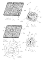
Figure 1 is a perspective view of a component of the cooking hob according to the invention; -
Figure 2 is an enlarged detail II offigure 1 ; -
Figure 3 is a perspective view similar tofigure 1 and showing a second embodiment of the invention; -
Figure 4 s an enlarged view of a detail IV offigure 3 ; -
Figure 5 is a top view of the detail offigure 2 ; -
Figure 6 is atop view of the component offigure 1 ; -
Figure 7 is a section taken along the line VII-VII offigure 6 where heaters and top glass plate are shown as well; and -
Figure 8 is a top view of the component offigure 3 . - With reference to the drawings, with 10 is shown a bottom panel of a cooking hob H (
figure 7 ) made of metal sheet. The bottom panel 10 comprises a bottomflat portion 10a and an angled lateral edge 10b which defines, together with atop glass plate 12, a sort of a box in which a plurality ofheaters 14 are contained. Thetop plate 12 and the bottom panel 10 can be connected in different ways, and since this kind of known connection is not relevant with regard to the present invention, it will not be described here in detail. - With reference to
figures 1, 2, 5 ,6 and 7 , according to a first embodiment of the invention the bottom panel 10 compriseshelicoidal slots 16 which defineconical springs 18 adapted to urge theheaters 14 against the top glass plate 12 (configuration shown infigure 7 ). - In the process for obtaining
conical springs 18, the metal sheet of the bottom panel 10 is firstly cut along a helicoidal slot, preferably by means of a laser beam. As shown infigure 5 , a first portion 16a of the slot starts at A and ends at B and a second portion 16b starts at B and ends at C. The two portions 16a and 16b are linked by a Z-shaped portion 16c whose central part is substantially radially directed, with a certain angle α with reference to radial direction. Such angle α is comprised between 10° and 30°, preferably around 20°. After theabove slot 16 is cut, the slotted portion undergoes a process of metal drawing/stamping in which the metal sheet is deformed in a mould so that a strip zone 17 inside the first portion 16a of theslot 16 assume a conical and helicoidal shape and acircular zone 15 inside the second portion 16b of thestrip 16 maintains its original flat configuration. Of course the process of cutting the slot and shaping the zone thereof can be carried out in a single shot as well. The configuration of the finalconical spring 18 is shown in detail infigure 5 , where thehelical slot 16 is widened after the metal drawing/stamping. - With an overall diameter of the
helicoidal slot 16 comprised between 35 and 45 mm, preferably around 40 mm, and with a thickness of the carbon steel sheet between 0,6 and 0,8 mm, the force that thespring 18 can exert is of the order of 10-20 N for an elastic vertical movement of about 3-4 mm, i.e. more than sufficient for assuring a good and permanent contact between theheaters 14 and theglass top plate 12. As shown in the lower right portion offigure 6 , for asingle heater 14 two ormore springs 18 can be used. - As it is clearly shown in
figure 6 , for ensuring that theheaters 14 are centered on their respectiveconical springs 18 the bottom plate 10 is provided with auxiliary U-shapedelongated slots 20 which define a plurality ofstrips 22 which are bent upward in order to define a predetermined zone where each heater has to be placed. Some ofsuch bent strips 22 can be used in cooperation with electrical terminals (not shown) of theheaters 14 in order to position correctly theheaters 14 and to avoid rotation thereof during the assembly of the cooking hob. - With reference to
figures 3, 4 and8 a second embodiment of the invention is shown in which U-shaped slots 24 of the bottom panel 10 definemetal strips 26 which are permanently and upwardly deformed so that each of them presents a firstslanted portion 26a stemming from the metal sheet and a secondelongated portion 26b which is substantially parallel to the metal sheet of the bottom panel 10. Eachshaped metal strip 26 defines therefore aleaf spring 30 integral with the bottom panel 10 which cooperates with an edge portion of theheater 14 in order to urge it against thetop glass plate 12.Such leaf springs 30 act also as centering means, particularly because eachend 26c of each secondelongated portion 26b of themetal strip 26 is bent upward. So, differently from the first embodiment where a singleconical spring 18 is enough for eachheater 14, in the second embodiment for eachheater 14 at least threeleaf springs 30 are necessary for eachheater 14. - In both the above embodiments it is possible to create, preferably in a zone around the springs, some embossed surfaces which prevent the springs from being deformed in a non elastic range during the assembly of the cooking hob. Such embossed surfaces (shown in the upper right portion only of
figures 6 and8 and referred to with reference numeral 29) act as a limit stop for the springs so that they can work only in a elastic stress-strain relation. - From the above description is clear how the overall construction of the cooking hob is simplified, either because the number of components is reduced or because it is not necessary to mount any spring clips since these latter are fully integrated with the metal box containing the heaters.
- The solution according to the invention is totally independent on the types of heaters that are used in the cooking hob, either radiant heating elements or induction heating elements. Moreover even if a conical shape of the embossed spring has been shown in connection with the first embodiment, other shapes can be used as well, for instance integral springs with a pyramid shape, either with a square or polygonal base. Similarly, in the second embodiment the
strips 26 can have a shape different from the rectilinear one, for instance L-shaped strips or curved strips. - The material and the thickness of the bottom panel 10 are not critical in so far these features are compatible with the range of elastic force that the integral spring has to exert on the heater. We deem that a person skilled in the art of metal drawing will have no problem in combining thickness and material in order to obtain the elastic force requested for each particular application.
Claims (15)
- Cooking hob (H) comprising a bottom panel (10), an upper plate (12) and at least a heating element (14) interposed between the bottom panel (10) and the upper plate (12), elastic means being interposed between the bottom panel (10) and the heating element (14) for urging this latter against the upper plate (12), characterized in that said elastic means (18, 30) is integral with the bottom panel (10, 10a).
- Cooking hob according to claim 1, wherein said elastic means comprises a shaped slot (16, 24) in the bottom panel (10. 10a) where a portion (17, 26) of the panel (10, 10a) defined by sais shaped slot (16, 24) is shaped upward in order to define a spring element (18, 30).
- Cooking hob according to claim 2, wherein said shaped slot is a helicoidal slot (16).
- Cooking hob according to claim 3, wherein said spring element (18) has a frustum of cone shape.
- Cooking hob according to claim 4, wherein said helicoidal slot (16) presents a first portion (16a) comprised between the bottom panel (10, 10a) and a conical zone (17) of the spring element (18) and a second portion (16b) comprised between said conical zone (17) and an upper zone (15) of the spring element (18), said two portions (16a, 16b) of the helicoidal slot (16) being linked by a substantially radial portion (16c).
- Cooking hob according to claim 5, wherein said substantially radial portion (16c) of the slot (16) presents an angle (α) comprised between 10° and 30° with reference to radial direction.
- Cooking hob according to claim 5 or 6, wherein the helicoidal slot (16) has an upper end (C) at whose level a flat circular upper zone (15) of the spring element (18) is placed and it is adapted to abut the heating element (14).
- Cooking hob according to any of claims 3-7, wherein the spring element (18) has an overall diameter comprised between 35 and 45 mm, and it can exert an elastic force comprised between 10 and 20 N.
- Cooking hob according to claim 2, wherein said shaped slot (24) is substantially U-shaped, the portion (26) of the bottom panel (10, 10a) defined by said slot (24) having a first slanted portion (26a) stemming from the bottom panel (10, 10a) and a second flat portion (26b) substantially parallel to the bottom panel (10, 10a) and adapted to abut the heating element (14).
- Cooking hob according to claim 9, wherein the second portion (26b) of the spring element (30) presents a bent end (26c) in order to center the heating element (14).
- Cooking hob according to any of claims 2-9, wherein the bottom panel (10, 10a) comprises auxiliary U-shaped slots (20) where a portion of the bottom panel (10, 10a) defined by said auxiliary slots is bent upward in order to define finger-shaped portions (22) adapted to center the heating element (14) on said spring elements (18, 30).
- Method for producing a cooking hob comprising a bottom panel (10), an upper plate (12) and at least a heating element (14) interposed between the bottom panel (10) and the upper plate (12), elastic means being interposed between the bottom panel (10) and the heating element (14) for urging this latter against the upper plate (12), characterized in that said elastic means is defined by cutting the bottom panel (10, 10a) in order to define at least a shaped slot (16, 24) and by deforming upward the portion (17, 26) of the bottom panel (10, 10a) defined by said slot.
- Method according to claim 12, wherein said bottom panel (10, 10a) is cut by a laser beam.
- Method according to claim 12 or 13, wherein the bottom panel (10, 10a) is cut along a helicoidal slot (16) and the portion of the bottom panel (10, 10a) inside said slot (16) is shaped so that is assume a conical shape.
- Method according to claim 14, wherein the bottom panel (10, 10a) is cut along a U-shaped slot (24) and the portion (26) of the bottom plate (10, 10a) defined by said slot (24) is shaped so that a first portion (26a) thereof is slanted and a second portion (26b) thereof is substantially parallel to the bottom panel (10, 10a).
Priority Applications (1)
| Application Number | Priority Date | Filing Date | Title |
|---|---|---|---|
| EP13161272.3A EP2784396B1 (en) | 2013-03-27 | 2013-03-27 | Cooking hob |
Applications Claiming Priority (1)
| Application Number | Priority Date | Filing Date | Title |
|---|---|---|---|
| EP13161272.3A EP2784396B1 (en) | 2013-03-27 | 2013-03-27 | Cooking hob |
Publications (2)
| Publication Number | Publication Date |
|---|---|
| EP2784396A1 true EP2784396A1 (en) | 2014-10-01 |
| EP2784396B1 EP2784396B1 (en) | 2017-04-19 |
Family
ID=48044620
Family Applications (1)
| Application Number | Title | Priority Date | Filing Date |
|---|---|---|---|
| EP13161272.3A Active EP2784396B1 (en) | 2013-03-27 | 2013-03-27 | Cooking hob |
Country Status (1)
| Country | Link |
|---|---|
| EP (1) | EP2784396B1 (en) |
Cited By (1)
| Publication number | Priority date | Publication date | Assignee | Title |
|---|---|---|---|---|
| EP4012268A1 (en) * | 2020-12-09 | 2022-06-15 | Miele & Cie. KG | Hob device |
Citations (13)
| Publication number | Priority date | Publication date | Assignee | Title |
|---|---|---|---|---|
| US2169182A (en) * | 1938-12-19 | 1939-08-08 | Prestole Devices Inc | Fastener |
| US2831388A (en) * | 1953-11-23 | 1958-04-22 | Prestole Corp | Apertured screw receiving deformity in sheet metal |
| DE2301928A1 (en) * | 1972-01-19 | 1973-08-02 | Elektra Bregenz Gmbh | ELECTRIC HEATING, HEATING AND / OR COOKING EQUIPMENT |
| DE3204760A1 (en) | 1982-02-11 | 1983-08-18 | Licentia Patent-Verwaltungs-Gmbh, 6000 Frankfurt | Cooking top made of glass-ceramic material with a radiant heating element |
| US5001328A (en) * | 1986-02-26 | 1991-03-19 | E.G.O. Eleckro-Gerate Blanc U. Fischer | Cooking unit with radiant heaters |
| GB2274497A (en) * | 1993-01-20 | 1994-07-27 | High Torque Fastener Syst Ltd | Screw and nut combination |
| DE19721776A1 (en) * | 1997-05-24 | 1998-11-26 | Schott Glas | Cooker hob carrier |
| EP1182369A2 (en) * | 2000-08-25 | 2002-02-27 | Piolax Inc. | Push nut |
| DE10306813A1 (en) * | 2003-02-18 | 2004-08-26 | BSH Bosch und Siemens Hausgeräte GmbH | A method for positioning radiant heating elements for the cooking fields of a glass ceramic top hob unit has a Y-shaped spring clip with formed tongues at an angle inhibiting accidental removal |
| DE102005007594A1 (en) * | 2005-02-18 | 2006-08-24 | BSH Bosch und Siemens Hausgeräte GmbH | Cooking hob, e.g. for domestic cooker, has holding device consisting of at least one fixing built out in one piece with assembly frame |
| WO2007133003A1 (en) | 2006-05-11 | 2007-11-22 | Lg Electronics Inc. | Cooktop, heater support device of cooktop, and heater support spring of cooktop |
| EP2144008A1 (en) | 2008-07-09 | 2010-01-13 | Electrolux Home Products Corporation N.V. | A mounting system for supporting a radiant heating device above a bottom panel of a cooking hob |
| EP2436989A1 (en) * | 2010-09-30 | 2012-04-04 | BSH Bosch und Siemens Hausgeräte GmbH | Cooker bottom case and cooker having the same |
-
2013
- 2013-03-27 EP EP13161272.3A patent/EP2784396B1/en active Active
Patent Citations (13)
| Publication number | Priority date | Publication date | Assignee | Title |
|---|---|---|---|---|
| US2169182A (en) * | 1938-12-19 | 1939-08-08 | Prestole Devices Inc | Fastener |
| US2831388A (en) * | 1953-11-23 | 1958-04-22 | Prestole Corp | Apertured screw receiving deformity in sheet metal |
| DE2301928A1 (en) * | 1972-01-19 | 1973-08-02 | Elektra Bregenz Gmbh | ELECTRIC HEATING, HEATING AND / OR COOKING EQUIPMENT |
| DE3204760A1 (en) | 1982-02-11 | 1983-08-18 | Licentia Patent-Verwaltungs-Gmbh, 6000 Frankfurt | Cooking top made of glass-ceramic material with a radiant heating element |
| US5001328A (en) * | 1986-02-26 | 1991-03-19 | E.G.O. Eleckro-Gerate Blanc U. Fischer | Cooking unit with radiant heaters |
| GB2274497A (en) * | 1993-01-20 | 1994-07-27 | High Torque Fastener Syst Ltd | Screw and nut combination |
| DE19721776A1 (en) * | 1997-05-24 | 1998-11-26 | Schott Glas | Cooker hob carrier |
| EP1182369A2 (en) * | 2000-08-25 | 2002-02-27 | Piolax Inc. | Push nut |
| DE10306813A1 (en) * | 2003-02-18 | 2004-08-26 | BSH Bosch und Siemens Hausgeräte GmbH | A method for positioning radiant heating elements for the cooking fields of a glass ceramic top hob unit has a Y-shaped spring clip with formed tongues at an angle inhibiting accidental removal |
| DE102005007594A1 (en) * | 2005-02-18 | 2006-08-24 | BSH Bosch und Siemens Hausgeräte GmbH | Cooking hob, e.g. for domestic cooker, has holding device consisting of at least one fixing built out in one piece with assembly frame |
| WO2007133003A1 (en) | 2006-05-11 | 2007-11-22 | Lg Electronics Inc. | Cooktop, heater support device of cooktop, and heater support spring of cooktop |
| EP2144008A1 (en) | 2008-07-09 | 2010-01-13 | Electrolux Home Products Corporation N.V. | A mounting system for supporting a radiant heating device above a bottom panel of a cooking hob |
| EP2436989A1 (en) * | 2010-09-30 | 2012-04-04 | BSH Bosch und Siemens Hausgeräte GmbH | Cooker bottom case and cooker having the same |
Cited By (1)
| Publication number | Priority date | Publication date | Assignee | Title |
|---|---|---|---|---|
| EP4012268A1 (en) * | 2020-12-09 | 2022-06-15 | Miele & Cie. KG | Hob device |
Also Published As
| Publication number | Publication date |
|---|---|
| EP2784396B1 (en) | 2017-04-19 |
Similar Documents
| Publication | Publication Date | Title |
|---|---|---|
| EP0047490B1 (en) | Electric cooking plate | |
| EP1886604B1 (en) | Additional bottom adapted to be fixed to the outer surface of the bottom of a vessel | |
| US9603202B2 (en) | Induction cooking appliance and method for assembling same | |
| EP2784396B1 (en) | Cooking hob | |
| DE102010029197A1 (en) | Cooking device, particularly oven, comprises cooking chamber wall and cooking chamber which is limited with drawer levels, where detection unit is provided for detecting occupancy of drawer levels by component part | |
| EP3531799B1 (en) | Induction heating device and method for controlling induction heating device | |
| AU4116399A (en) | Method for the manufacture of an electrical switching device and electrical switching device | |
| US20160123602A1 (en) | Economical and versatile system for fixing a hob in a worktop | |
| EP1039233A2 (en) | Mounting profile for cooking plate | |
| EP2144008B1 (en) | A mounting system for supporting a radiant heating device above a bottom panel of a cooking hob | |
| US2357150A (en) | Heater | |
| EP0967839A2 (en) | Cooking plate with operating unit determining its power level | |
| US11213163B2 (en) | Heating magnetic body for cooking container for an induction range | |
| CN101365915A (en) | Fastening element for attaching a part to a supporting element | |
| DE19527823A1 (en) | Hob unit with several hotplates arranged below a plate | |
| US1705702A (en) | Concentric hot plate | |
| EP3285009A1 (en) | Pressing element and induction hob comprising a pressing element | |
| CN103348764B (en) | induction heating cooker | |
| EP3282816B1 (en) | Inductive cooking system | |
| EP2117281B1 (en) | Hotplate with a hotplate field and method for controlling a cooking process | |
| DE2329435C3 (en) | Induction cooker | |
| US20200128631A1 (en) | Induction cooktop device | |
| EP3040622A1 (en) | A home appliance having a coupling element | |
| KR20180126104A (en) | Manufacturing method of sector gear | |
| EP3182019B1 (en) | A cooking appliance having a coupling element |
Legal Events
| Date | Code | Title | Description |
|---|---|---|---|
| 17P | Request for examination filed |
Effective date: 20130327 |
|
| AK | Designated contracting states |
Kind code of ref document: A1 Designated state(s): AL AT BE BG CH CY CZ DE DK EE ES FI FR GB GR HR HU IE IS IT LI LT LU LV MC MK MT NL NO PL PT RO RS SE SI SK SM TR |
|
| AX | Request for extension of the european patent |
Extension state: BA ME |
|
| PUAI | Public reference made under article 153(3) epc to a published international application that has entered the european phase |
Free format text: ORIGINAL CODE: 0009012 |
|
| R17P | Request for examination filed (corrected) |
Effective date: 20150325 |
|
| RBV | Designated contracting states (corrected) |
Designated state(s): AL AT BE BG CH CY CZ DE DK EE ES FI FR GB GR HR HU IE IS IT LI LT LU LV MC MK MT NL NO PL PT RO RS SE SI SK SM TR |
|
| 17Q | First examination report despatched |
Effective date: 20151222 |
|
| REG | Reference to a national code |
Ref country code: DE Ref legal event code: R079 Ref document number: 602013019924 Country of ref document: DE Free format text: PREVIOUS MAIN CLASS: F24C0007060000 Ipc: H05B0006120000 |
|
| RIC1 | Information provided on ipc code assigned before grant |
Ipc: H05B 3/74 20060101ALI20161209BHEP Ipc: F24C 15/10 20060101ALI20161209BHEP Ipc: F24C 7/06 20060101ALI20161209BHEP Ipc: H05B 6/12 20060101AFI20161209BHEP |
|
| GRAP | Despatch of communication of intention to grant a patent |
Free format text: ORIGINAL CODE: EPIDOSNIGR1 |
|
| GRAS | Grant fee paid |
Free format text: ORIGINAL CODE: EPIDOSNIGR3 |
|
| INTG | Intention to grant announced |
Effective date: 20170130 |
|
| GRAA | (expected) grant |
Free format text: ORIGINAL CODE: 0009210 |
|
| AK | Designated contracting states |
Kind code of ref document: B1 Designated state(s): AL AT BE BG CH CY CZ DE DK EE ES FI FR GB GR HR HU IE IS IT LI LT LU LV MC MK MT NL NO PL PT RO RS SE SI SK SM TR |
|
| REG | Reference to a national code |
Ref country code: GB Ref legal event code: FG4D |
|
| REG | Reference to a national code |
Ref country code: CH Ref legal event code: EP |
|
| REG | Reference to a national code |
Ref country code: AT Ref legal event code: REF Ref document number: 887041 Country of ref document: AT Kind code of ref document: T Effective date: 20170515 |
|
| REG | Reference to a national code |
Ref country code: IE Ref legal event code: FG4D |
|
| REG | Reference to a national code |
Ref country code: DE Ref legal event code: R096 Ref document number: 602013019924 Country of ref document: DE |
|
| REG | Reference to a national code |
Ref country code: NL Ref legal event code: MP Effective date: 20170419 |
|
| REG | Reference to a national code |
Ref country code: LT Ref legal event code: MG4D |
|
| REG | Reference to a national code |
Ref country code: AT Ref legal event code: MK05 Ref document number: 887041 Country of ref document: AT Kind code of ref document: T Effective date: 20170419 |
|
| PG25 | Lapsed in a contracting state [announced via postgrant information from national office to epo] |
Ref country code: NL Free format text: LAPSE BECAUSE OF FAILURE TO SUBMIT A TRANSLATION OF THE DESCRIPTION OR TO PAY THE FEE WITHIN THE PRESCRIBED TIME-LIMIT Effective date: 20170419 |
|
| PG25 | Lapsed in a contracting state [announced via postgrant information from national office to epo] |
Ref country code: AT Free format text: LAPSE BECAUSE OF FAILURE TO SUBMIT A TRANSLATION OF THE DESCRIPTION OR TO PAY THE FEE WITHIN THE PRESCRIBED TIME-LIMIT Effective date: 20170419 Ref country code: ES Free format text: LAPSE BECAUSE OF FAILURE TO SUBMIT A TRANSLATION OF THE DESCRIPTION OR TO PAY THE FEE WITHIN THE PRESCRIBED TIME-LIMIT Effective date: 20170419 Ref country code: LT Free format text: LAPSE BECAUSE OF FAILURE TO SUBMIT A TRANSLATION OF THE DESCRIPTION OR TO PAY THE FEE WITHIN THE PRESCRIBED TIME-LIMIT Effective date: 20170419 Ref country code: GR Free format text: LAPSE BECAUSE OF FAILURE TO SUBMIT A TRANSLATION OF THE DESCRIPTION OR TO PAY THE FEE WITHIN THE PRESCRIBED TIME-LIMIT Effective date: 20170720 Ref country code: NO Free format text: LAPSE BECAUSE OF FAILURE TO SUBMIT A TRANSLATION OF THE DESCRIPTION OR TO PAY THE FEE WITHIN THE PRESCRIBED TIME-LIMIT Effective date: 20170719 Ref country code: FI Free format text: LAPSE BECAUSE OF FAILURE TO SUBMIT A TRANSLATION OF THE DESCRIPTION OR TO PAY THE FEE WITHIN THE PRESCRIBED TIME-LIMIT Effective date: 20170419 Ref country code: HR Free format text: LAPSE BECAUSE OF FAILURE TO SUBMIT A TRANSLATION OF THE DESCRIPTION OR TO PAY THE FEE WITHIN THE PRESCRIBED TIME-LIMIT Effective date: 20170419 |
|
| PG25 | Lapsed in a contracting state [announced via postgrant information from national office to epo] |
Ref country code: RS Free format text: LAPSE BECAUSE OF FAILURE TO SUBMIT A TRANSLATION OF THE DESCRIPTION OR TO PAY THE FEE WITHIN THE PRESCRIBED TIME-LIMIT Effective date: 20170419 Ref country code: PL Free format text: LAPSE BECAUSE OF FAILURE TO SUBMIT A TRANSLATION OF THE DESCRIPTION OR TO PAY THE FEE WITHIN THE PRESCRIBED TIME-LIMIT Effective date: 20170419 Ref country code: LV Free format text: LAPSE BECAUSE OF FAILURE TO SUBMIT A TRANSLATION OF THE DESCRIPTION OR TO PAY THE FEE WITHIN THE PRESCRIBED TIME-LIMIT Effective date: 20170419 Ref country code: BG Free format text: LAPSE BECAUSE OF FAILURE TO SUBMIT A TRANSLATION OF THE DESCRIPTION OR TO PAY THE FEE WITHIN THE PRESCRIBED TIME-LIMIT Effective date: 20170719 Ref country code: SE Free format text: LAPSE BECAUSE OF FAILURE TO SUBMIT A TRANSLATION OF THE DESCRIPTION OR TO PAY THE FEE WITHIN THE PRESCRIBED TIME-LIMIT Effective date: 20170419 Ref country code: IS Free format text: LAPSE BECAUSE OF FAILURE TO SUBMIT A TRANSLATION OF THE DESCRIPTION OR TO PAY THE FEE WITHIN THE PRESCRIBED TIME-LIMIT Effective date: 20170819 |
|
| REG | Reference to a national code |
Ref country code: DE Ref legal event code: R097 Ref document number: 602013019924 Country of ref document: DE |
|
| PG25 | Lapsed in a contracting state [announced via postgrant information from national office to epo] |
Ref country code: SK Free format text: LAPSE BECAUSE OF FAILURE TO SUBMIT A TRANSLATION OF THE DESCRIPTION OR TO PAY THE FEE WITHIN THE PRESCRIBED TIME-LIMIT Effective date: 20170419 Ref country code: DK Free format text: LAPSE BECAUSE OF FAILURE TO SUBMIT A TRANSLATION OF THE DESCRIPTION OR TO PAY THE FEE WITHIN THE PRESCRIBED TIME-LIMIT Effective date: 20170419 Ref country code: RO Free format text: LAPSE BECAUSE OF FAILURE TO SUBMIT A TRANSLATION OF THE DESCRIPTION OR TO PAY THE FEE WITHIN THE PRESCRIBED TIME-LIMIT Effective date: 20170419 Ref country code: EE Free format text: LAPSE BECAUSE OF FAILURE TO SUBMIT A TRANSLATION OF THE DESCRIPTION OR TO PAY THE FEE WITHIN THE PRESCRIBED TIME-LIMIT Effective date: 20170419 Ref country code: CZ Free format text: LAPSE BECAUSE OF FAILURE TO SUBMIT A TRANSLATION OF THE DESCRIPTION OR TO PAY THE FEE WITHIN THE PRESCRIBED TIME-LIMIT Effective date: 20170419 |
|
| PLBE | No opposition filed within time limit |
Free format text: ORIGINAL CODE: 0009261 |
|
| REG | Reference to a national code |
Ref country code: FR Ref legal event code: PLFP Year of fee payment: 6 |
|
| STAA | Information on the status of an ep patent application or granted ep patent |
Free format text: STATUS: NO OPPOSITION FILED WITHIN TIME LIMIT |
|
| PG25 | Lapsed in a contracting state [announced via postgrant information from national office to epo] |
Ref country code: SM Free format text: LAPSE BECAUSE OF FAILURE TO SUBMIT A TRANSLATION OF THE DESCRIPTION OR TO PAY THE FEE WITHIN THE PRESCRIBED TIME-LIMIT Effective date: 20170419 |
|
| 26N | No opposition filed |
Effective date: 20180122 |
|
| PG25 | Lapsed in a contracting state [announced via postgrant information from national office to epo] |
Ref country code: SI Free format text: LAPSE BECAUSE OF FAILURE TO SUBMIT A TRANSLATION OF THE DESCRIPTION OR TO PAY THE FEE WITHIN THE PRESCRIBED TIME-LIMIT Effective date: 20170419 |
|
| REG | Reference to a national code |
Ref country code: CH Ref legal event code: PL |
|
| PG25 | Lapsed in a contracting state [announced via postgrant information from national office to epo] |
Ref country code: MC Free format text: LAPSE BECAUSE OF FAILURE TO SUBMIT A TRANSLATION OF THE DESCRIPTION OR TO PAY THE FEE WITHIN THE PRESCRIBED TIME-LIMIT Effective date: 20170419 |
|
| REG | Reference to a national code |
Ref country code: BE Ref legal event code: MM Effective date: 20180331 |
|
| REG | Reference to a national code |
Ref country code: IE Ref legal event code: MM4A |
|
| PG25 | Lapsed in a contracting state [announced via postgrant information from national office to epo] |
Ref country code: LU Free format text: LAPSE BECAUSE OF NON-PAYMENT OF DUE FEES Effective date: 20180327 |
|
| PG25 | Lapsed in a contracting state [announced via postgrant information from national office to epo] |
Ref country code: IE Free format text: LAPSE BECAUSE OF NON-PAYMENT OF DUE FEES Effective date: 20180327 |
|
| PG25 | Lapsed in a contracting state [announced via postgrant information from national office to epo] |
Ref country code: CH Free format text: LAPSE BECAUSE OF NON-PAYMENT OF DUE FEES Effective date: 20180331 Ref country code: BE Free format text: LAPSE BECAUSE OF NON-PAYMENT OF DUE FEES Effective date: 20180331 Ref country code: LI Free format text: LAPSE BECAUSE OF NON-PAYMENT OF DUE FEES Effective date: 20180331 |
|
| PG25 | Lapsed in a contracting state [announced via postgrant information from national office to epo] |
Ref country code: MT Free format text: LAPSE BECAUSE OF NON-PAYMENT OF DUE FEES Effective date: 20180327 |
|
| PG25 | Lapsed in a contracting state [announced via postgrant information from national office to epo] |
Ref country code: TR Free format text: LAPSE BECAUSE OF FAILURE TO SUBMIT A TRANSLATION OF THE DESCRIPTION OR TO PAY THE FEE WITHIN THE PRESCRIBED TIME-LIMIT Effective date: 20170419 |
|
| PG25 | Lapsed in a contracting state [announced via postgrant information from national office to epo] |
Ref country code: PT Free format text: LAPSE BECAUSE OF FAILURE TO SUBMIT A TRANSLATION OF THE DESCRIPTION OR TO PAY THE FEE WITHIN THE PRESCRIBED TIME-LIMIT Effective date: 20170419 Ref country code: HU Free format text: LAPSE BECAUSE OF FAILURE TO SUBMIT A TRANSLATION OF THE DESCRIPTION OR TO PAY THE FEE WITHIN THE PRESCRIBED TIME-LIMIT; INVALID AB INITIO Effective date: 20130327 |
|
| PG25 | Lapsed in a contracting state [announced via postgrant information from national office to epo] |
Ref country code: CY Free format text: LAPSE BECAUSE OF FAILURE TO SUBMIT A TRANSLATION OF THE DESCRIPTION OR TO PAY THE FEE WITHIN THE PRESCRIBED TIME-LIMIT Effective date: 20170419 Ref country code: MK Free format text: LAPSE BECAUSE OF NON-PAYMENT OF DUE FEES Effective date: 20170419 |
|
| PG25 | Lapsed in a contracting state [announced via postgrant information from national office to epo] |
Ref country code: AL Free format text: LAPSE BECAUSE OF FAILURE TO SUBMIT A TRANSLATION OF THE DESCRIPTION OR TO PAY THE FEE WITHIN THE PRESCRIBED TIME-LIMIT Effective date: 20170419 |
|
| P01 | Opt-out of the competence of the unified patent court (upc) registered |
Effective date: 20230522 |
|
| PGFP | Annual fee paid to national office [announced via postgrant information from national office to epo] |
Ref country code: DE Payment date: 20250327 Year of fee payment: 13 |
|
| PGFP | Annual fee paid to national office [announced via postgrant information from national office to epo] |
Ref country code: FR Payment date: 20250324 Year of fee payment: 13 |
|
| PGFP | Annual fee paid to national office [announced via postgrant information from national office to epo] |
Ref country code: IT Payment date: 20250307 Year of fee payment: 13 Ref country code: GB Payment date: 20250325 Year of fee payment: 13 |