EP2784269A1 - Wall section for the working gas annulus of a gas turbine engine, corresponding shroud ring and gas turbine engine - Google Patents
Wall section for the working gas annulus of a gas turbine engine, corresponding shroud ring and gas turbine engine Download PDFInfo
- Publication number
- EP2784269A1 EP2784269A1 EP14161420.6A EP14161420A EP2784269A1 EP 2784269 A1 EP2784269 A1 EP 2784269A1 EP 14161420 A EP14161420 A EP 14161420A EP 2784269 A1 EP2784269 A1 EP 2784269A1
- Authority
- EP
- European Patent Office
- Prior art keywords
- wall section
- turbine engine
- gas turbine
- previous
- section according
- Prior art date
- Legal status (The legal status is an assumption and is not a legal conclusion. Google has not performed a legal analysis and makes no representation as to the accuracy of the status listed.)
- Withdrawn
Links
Images

Classifications
-
- F—MECHANICAL ENGINEERING; LIGHTING; HEATING; WEAPONS; BLASTING
- F01—MACHINES OR ENGINES IN GENERAL; ENGINE PLANTS IN GENERAL; STEAM ENGINES
- F01D—NON-POSITIVE DISPLACEMENT MACHINES OR ENGINES, e.g. STEAM TURBINES
- F01D25/00—Component parts, details, or accessories, not provided for in, or of interest apart from, other groups
- F01D25/28—Supporting or mounting arrangements, e.g. for turbine casing
-
- F—MECHANICAL ENGINEERING; LIGHTING; HEATING; WEAPONS; BLASTING
- F01—MACHINES OR ENGINES IN GENERAL; ENGINE PLANTS IN GENERAL; STEAM ENGINES
- F01D—NON-POSITIVE DISPLACEMENT MACHINES OR ENGINES, e.g. STEAM TURBINES
- F01D11/00—Preventing or minimising internal leakage of working-fluid, e.g. between stages
- F01D11/08—Preventing or minimising internal leakage of working-fluid, e.g. between stages for sealing space between rotor blade tips and stator
- F01D11/12—Preventing or minimising internal leakage of working-fluid, e.g. between stages for sealing space between rotor blade tips and stator using a rubstrip, e.g. erodible. deformable or resiliently-biased part
- F01D11/122—Preventing or minimising internal leakage of working-fluid, e.g. between stages for sealing space between rotor blade tips and stator using a rubstrip, e.g. erodible. deformable or resiliently-biased part with erodable or abradable material
-
- F—MECHANICAL ENGINEERING; LIGHTING; HEATING; WEAPONS; BLASTING
- F01—MACHINES OR ENGINES IN GENERAL; ENGINE PLANTS IN GENERAL; STEAM ENGINES
- F01D—NON-POSITIVE DISPLACEMENT MACHINES OR ENGINES, e.g. STEAM TURBINES
- F01D11/00—Preventing or minimising internal leakage of working-fluid, e.g. between stages
- F01D11/08—Preventing or minimising internal leakage of working-fluid, e.g. between stages for sealing space between rotor blade tips and stator
-
- F—MECHANICAL ENGINEERING; LIGHTING; HEATING; WEAPONS; BLASTING
- F05—INDEXING SCHEMES RELATING TO ENGINES OR PUMPS IN VARIOUS SUBCLASSES OF CLASSES F01-F04
- F05D—INDEXING SCHEME FOR ASPECTS RELATING TO NON-POSITIVE-DISPLACEMENT MACHINES OR ENGINES, GAS-TURBINES OR JET-PROPULSION PLANTS
- F05D2240/00—Components
- F05D2240/10—Stators
- F05D2240/11—Shroud seal segments
-
- F—MECHANICAL ENGINEERING; LIGHTING; HEATING; WEAPONS; BLASTING
- F05—INDEXING SCHEMES RELATING TO ENGINES OR PUMPS IN VARIOUS SUBCLASSES OF CLASSES F01-F04
- F05D—INDEXING SCHEME FOR ASPECTS RELATING TO NON-POSITIVE-DISPLACEMENT MACHINES OR ENGINES, GAS-TURBINES OR JET-PROPULSION PLANTS
- F05D2240/00—Components
- F05D2240/90—Mounting on supporting structures or systems
- F05D2240/91—Mounting on supporting structures or systems on a stationary structure
-
- F—MECHANICAL ENGINEERING; LIGHTING; HEATING; WEAPONS; BLASTING
- F05—INDEXING SCHEMES RELATING TO ENGINES OR PUMPS IN VARIOUS SUBCLASSES OF CLASSES F01-F04
- F05D—INDEXING SCHEME FOR ASPECTS RELATING TO NON-POSITIVE-DISPLACEMENT MACHINES OR ENGINES, GAS-TURBINES OR JET-PROPULSION PLANTS
- F05D2250/00—Geometry
- F05D2250/10—Two-dimensional
- F05D2250/14—Two-dimensional elliptical
-
- F—MECHANICAL ENGINEERING; LIGHTING; HEATING; WEAPONS; BLASTING
- F05—INDEXING SCHEMES RELATING TO ENGINES OR PUMPS IN VARIOUS SUBCLASSES OF CLASSES F01-F04
- F05D—INDEXING SCHEME FOR ASPECTS RELATING TO NON-POSITIVE-DISPLACEMENT MACHINES OR ENGINES, GAS-TURBINES OR JET-PROPULSION PLANTS
- F05D2260/00—Function
- F05D2260/30—Retaining components in desired mutual position
- F05D2260/31—Retaining bolts or nuts
- F05D2260/311—Retaining bolts or nuts of the frangible or shear type
-
- F—MECHANICAL ENGINEERING; LIGHTING; HEATING; WEAPONS; BLASTING
- F05—INDEXING SCHEMES RELATING TO ENGINES OR PUMPS IN VARIOUS SUBCLASSES OF CLASSES F01-F04
- F05D—INDEXING SCHEME FOR ASPECTS RELATING TO NON-POSITIVE-DISPLACEMENT MACHINES OR ENGINES, GAS-TURBINES OR JET-PROPULSION PLANTS
- F05D2300/00—Materials; Properties thereof
- F05D2300/60—Properties or characteristics given to material by treatment or manufacturing
- F05D2300/603—Composites; e.g. fibre-reinforced
- F05D2300/6033—Ceramic matrix composites [CMC]
Definitions
- the present invention relates to a wall section for the working gas annulus of a gas turbine engine, such as a seal segment for a shroud ring of a rotor of a gas turbine engine, and particularly, but not exclusively, to such a wall section which is formed of ceramic.
- EP 0751104 discloses a ceramic segment having an abradable seal which is suitable for use with nickel base turbine blades
- EP 1965030 discloses a hollow section ceramic seal segment.
- a conventional method of attaching shroud segments to other components is a "birdmouth" type assembly, in which a slot in one component is attached to a hook in another component. When assembled, the two components can then locate across an interface which is perpendicular to the direction of the primary load.
- US 2007/0031258 proposes an attachment method for a ceramic shroud segment in which pins are inserted in respective bores formed in the segment. The pins are then supported by U-shaped clevis bars. To reduce the contact stress of the pins on the ceramic, US 2007/0031258 proposes introducing a compliant layer such as a bushing in the bore and increasing the diameter of the pins.
- the present invention provides a wall section for the working gas annulus of a gas turbine engine, wherein the wall section has two or more spaced passageways such that, in use, a respective support bar is contained within each passageway, the support bars allowing attachment of the wall section to the engine casing, characterised by: each passageway having an elliptical or substantially elliptical cross-section with a minor diameter and a major diameter, the minor diameter being substantially aligned with the radial direction, and the respective support bar having a correspondingly elliptical or substantially elliptical cross-section for a close fit in the passageway.
- a relatively large contact area can be achieved between the support bar and the wall section, even if the cross-sections of the bar and the respective passageway become misaligned. In this way, high contact stresses in the wall section can be avoided, and other precautions to reduce contact stresses, such as over-sized cross-sectional areas and compliant layers, may be unnecessary.
- the elliptical or substantially elliptical cross-sections are robust in terms of manufacturing tolerances.
- the present invention provides a wall section according to the first aspect and containing respective support bars in the passageways.
- the present invention provides a shroud ring of a rotor of a gas turbine engine, the shroud ring including an annular array of wall sections of the first or second aspect, the wall sections being seal segments of the shroud ring.
- the present invention provides a gas turbine engine having the shroud ring of the third aspect.
- each passageway has an elliptical cross-section
- the respective support bar has a correspondingly elliptical cross-section.
- substantially elliptical cross-sections can provide at least some of the benefits of true elliptical cross-sections.
- the wall section can be a seal segment for a shroud ring of a rotor of a gas turbine engine, the seal segment being positioned, in use, radially adjacent the rotor.
- the wall section is also possible, however, is for the wall section to be an annulus filler, e.g. positioned forward of the inner or outer platform of a nozzle guide vane.
- the wall section may be formed of ceramic, and, in particular, may be formed of ceramic matrix composite.
- the wall section may be formed of continuous fibre reinforced ceramic matrix composite.
- the reinforcing fibres may be contained in layered plies which extend parallel to the annulus-facing surface of the wall section.
- An abradable ceramic coating can form the annulus-facing surface of the wall section.
- the coating may comprise hollow ceramic spheres in a ceramic matrix, e.g. as disclosed in EP 0751104 .
- An abradable coating is of particular utility for forming the radially inward facing surface of a seal segment.
- a thermal barrier coating can form the annulus-facing surface of the wall section.
- the coating at the annulus-facing surface can be a dual purpose abradable/ thermal barrier coating.
- the support bars may be metallic. Typically, therefore, the support bars have a higher coefficient of thermal expansion than the seal segment. Thus the support bars may be a clearance fit in the passageways when cold, transitioning to a sliding interference fit in the passageways when at operating temperature. Another option, however, is that support bars may maintain the clearance though all operating conditions.
- the ratio of the major diameter to the minor diameter may be 1.5 or more.
- the ratio of the major diameter to the minor diameter may be 5 or less.
- the passageways may be coated or surface treated to better distribute contact loads from the support bars, create a hardwearing face, and /or protect from gasses or chemical attack.
- the passageways may extend in a fore and aft direction and may be circumferentially spaced from each other.
- the passageways may extend from a front face to rear face of the wall section, the support bars projecting from the front and rear faces for mounting of the wall section at complementary formations of the engine casing.
- the support bars can still project from the front and rear faces for mounting of the section at complementary formations of the engine casing.
- the support bars may be cantilevered from the formations.
- the complementary formations provided by the casing of the engine are formed by a backing plate of a shroud ring, although other arrangements for providing the formations may be may be adopted.
- the wall section may have circumferentially opposing side faces, each side face providing a respective slot which extends in the fore and aft direction and which contains a respective strip seal for sealing the wall section to a circumferentially adjacent wall section.
- the wall section may have a substantially plate-like shape, i.e. with passageways in the form of through-holes extending in the plain of the plate.
- the wall section may have a plate-like base forming the annulus surface of the section, and walls projecting radially therefrom away from the annulus e.g. to define a space for cooling air therebetween.
- Each passageway can then be formed by a pair of aligned through-holes in opposing (e.g. front and rear) walls.
- Other configurations for the wall section are also possible.
- the support bars may attach the wall section into the engine casing directly or indirectly e.g. via a (metallic or ceramic) holder or carrier arrangement.
- the support bars may be configured to reduce or prevent axial sliding of the wall section thereon under axial "piston" loading of the section.
- One option is for one or more of the support bars to have an abutment formation which abuts against a rearward facing surface of the wall section.
- Another option is for one or more of the support bars to have a stepped or gradual increase in diameter to produce a tighter fit if the wall section slides axially thereon.
- the support bars may be straight. Alternatively, however, the bars may be bent or curved, for example so that they can compensate for distortions (i.e. bends or curves in the opposite direction) caused by thermal gradients to which they may be exposed in service.
- a ducted fan gas turbine engine generally indicated at 10 has a principal and rotational axis X-X.
- the engine comprises, in axial flow series, an air intake 11, a propulsive fan 12, an intermediate pressure compressor 13, a high-pressure compressor 14, combustion equipment 15, a high-pressure turbine 16, and intermediate pressure turbine 17, a low-pressure turbine 18 and a core engine exhaust nozzle 19.
- a nacelle 21 generally surrounds the engine 10 and defines the intake 11, a bypass duct 22 and a bypass exhaust nozzle 23.
- the gas turbine engine 10 works in a conventional manner so that air entering the intake 11 is accelerated by the fan 12 to produce two air flows: a first air flow A into the intermediate pressure compressor 13 and a second air flow B which passes through the bypass duct 22 to provide propulsive thrust.
- the intermediate pressure compressor 13 compresses the air flow A directed into it before delivering that air to the high pressure compressor 14 where further compression takes place.
- the compressed air exhausted from the high-pressure compressor 14 is directed into the combustion equipment 15 where it is mixed with fuel and the mixture combusted.
- the resultant hot combustion products then expand through, and thereby drive the high, intermediate and low-pressure turbines 16, 17, 18 before being exhausted through the nozzle 19 to provide additional propulsive thrust.
- the high, intermediate and low-pressure turbines respectively drive the high and intermediate pressure compressors 14, 13 and the fan 12 by suitable interconnecting shafts.
- the high pressure turbine 16 includes an annular array of radially extending rotor aerofoil blades 24, the radially outer part of one of which can be seen if reference is now made to Figure 2 , which shows schematically a sectional elevation through a portion of the high pressure turbine. Hot turbine gases flow over nozzle guide vanes 25 and the aerofoil blades 24 in the direction generally indicated by the arrow.
- a shroud ring 27 in accordance with the present invention is positioned radially outwardly of the shroudless aerofoil blades 24.
- the shroud ring 27 serves to define the radially outer extent of a short length of the gas passage 26 through the high pressure turbine 16.
- the turbine gases flowing over the radially inward facing surface of the shroud ring 27 are at extremely high temperatures. Consequently, at least that portion of the ring 27 must be constructed from a material which is capable of withstanding those temperatures whilst maintaining its structural integrity. Ceramic materials are particularly well suited to this sort of application.
- the shroud ring 27 is formed from an annular array of seal segments 28 (i.e. wall sections) attached to a part of the engine casing which takes the form of an annular, metallic backing plate 29 having a central portion and radially inwardly projecting, front and rear flanges. Cooling air for the ring 27 enters a space 30 formed between the backing plate 29 and each segment 28, the air being continuously replenished as it leaks, under a pressure gradient, into the working gas annulus through suitable holes (not shown) in the segments 28.
- the backing plate 29 is sealed at its front and rear sides to adjacent parts of the engine casing by piston ring-type sealing formations 31 of conventional design.
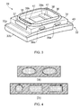
- Figure 3 shows schematically a perspective view of one of the seal segments 28.
- the segment 28 has a substantially plate-like, rectangular base portion 32.
- the radially outer part 33a of the base portion is formed from continuous fibre reinforced ceramic matrix composite.
- the radially inner part 33b of the base portion is formed by an abradable coating comprising hollow ceramic spheres in a ceramic matrix, as disclosed in EP 0751104 .
- the abradable coating also acts as a thermal barrier coating.
- the seal segment 28 has pair of radially outwardly projecting front 34 and rear 35 walls at the front and rear edges of the base portion 32, and further has a pair of radially outwardly projecting side walls 36, 37 which join at their ends to the front and rear walls to enclose the space 30 for cooling air therebetween.
- a gasket-type sealing ring 38 runs around the top surface of the walls for sealing with the backing plate 29.
- Two circumferentially spaced passageways each in the form of a front through-hole 39a of elliptical cross-section in the front wall 34 and an aligned rear through-hole 39b of the same elliptical cross-section in the rear wall 35, extends from the front to the rear face of the segment 28.
- the minor diameter of the elliptical cross-section is substantially aligned with the radial direction.
- the front and rear faces each contain a shelf 40 which runs between circumferentially opposing side faces of the base portion 32 of the segment 28 at the foot of the respective wall 34, 35.
- the passageways contain respective cylindrical metallic support bars 41, of correspondingly elliptical cross-section.
- the support bars 41 project from the entrances of the through holes 39a, 39b to be approximately level at their ends with the front and rear surfaces of the base portion 32.
- the seal segment is offered to the plate 29 so that the front and rear shelves 40 engage complimentary surfaces formed at the radially inner ends of the front and rear flanges of the plate 29, and the sealing ring 38 seals to the central portion of the plate 29.
- the through holes 39a, 39b are aligned with matching holes formed in the flanges, and the support bars 41 are inserted through the through-holes 39a, 39b and the matching holes to attach the segment 28 to the plate 29.
- the bars may make fixed or sliding joints to the plate.
- each front through-hole 39a and each rear through-hole 39b to form a respective passageway, whereby four separate supports bars can be inserted in the through-holes, two at the front and two at the rear.
- the supports bars in this configuration can be cantilevered from the plate 29. Further, pairs of front 39a and rear 39b through-holes do not need to be aligned.
- the support bars 41 are a clearance fit in the through-holes 39a, 39b, but at operating conditions differential thermal expansion between the metal of the support bars 41 and the ceramic matrix composite of the seal segment 28 changes this to a sliding interference fit.
- the through-hole and support bar attachment technique avoids the use of sharp geometries, such as hooks or internal corners, which can cause undesirable stress concentrations in ceramics.
- the support bars may be configured to reduce or prevent axial sliding of the seal segment thereon under axial "piston" loading of the segment.
- the support bars may have abutment formations which abut the rear face of the rear wall 35 to prevent such sliding.
- the through-hole 39a, 39b may be coated or surface treated to better distribute contact loads from the support bars 41, create a hardwearing face, and /or protect from gasses or chemical attack.
- the radially outer part 33a of the base portion 32 and the walls 34, 35, 36, 37 can be produced from fibre reinforced ceramic matrix composite. More particularly, these elements can be produced by stacking successive plies formed from a cloth of woven continuous reinforcement. As each ply is stacked it is covered in a slurry containing a binder, water and ceramic. Alternatively, the plies may be pre-impregnated with the slurry. The stacked plies are pressed to remove excess slurry, and heated which allows, the binder to form a self-supporting green form. The green is then heated in a furnace to drive off residual moisture and sinter the ceramic particles to form the surrounding matrix. Lightly curved or straight-sided blocks can readily be formed in this way.
- through-holes 39a, 39b and the shelves 40 can be produced by subsequent machining. In a further laying up and firing step, additional plies can then be used to line the through-holes to better distribute contact loads.
- Another option for lining the through-holes is to bond sintered lining tubes in the holes using ceramic cement. Indeed, more generally, at least some of the walls 34, 35, 36, 37 may be produced separately, and then bonded to the radially outer part 33a of the base portion 32 using ceramic cement.
- the reinforcement fibres can be Nextel720TM and/or Nextel610TM alumina silicate fibres available from 3M
- the ceramic particles can be alumina particles or a mixture of alumina and silicate particles.
- Ox/Ox ceramic matrix composite materials are examples of Ox/Ox ceramic matrix composite materials.
- a SiC/SiC seal segment can be manufactured by CVI (Chemical vapour infiltration) and/or MI (melt infiltration).
- the radially inner part 33b of the base portion 32 can be moulded directly on the radially outer part 32a or cast and fired separately to the required shape (and typically also machined) and then glued to the radially outer part 32a, as discussed in EP 0751104 .
- Figure 4(a) shows schematically at left a cross-section through a support bar and the seal segment with the ellipses of the support bar and through-hole aligned, and at right the same cross-section but with the support bar and through-hole misaligned.
- the width of the respective contact area between the support bar and the seal segment is indicated in each case by the distance between the outer of the three vertical lines.
- the elliptical shape, combined with the elliptical minor diameter being substantially aligned with the radial direction, ensures that the contact area is relatively wide independent of support bar to through-hole alignment.
- Figure 4(b) shows schematically at left a cross-section through a support bar and seal segment in which the support bar and through-hole have circular cross-sections.
- the support bar does not tend to misalign, but the contact area between the support bar and the seal segment is relatively narrow.
- Figure 4(b) also shows at centre, a cross-section through a support bar and seal segment in which the support bar and through-hole have rounded corner, rectangular cross-sections.
- the support bar and through-hole are fully aligned, which leads to a very wide contact area.
- the contact area narrows substantially.
- the ratio of the major elliptical diameter to the minor elliptical diameter of a support bar and through-hole is in the range from 1.5 to 5. If the ratio is less than 1.5, the ellipse tends to the circular, and the contact becomes relatively narrow. On the other hand if the ratio is greater than 5, the sides of the support bars become relatively sharp, which can cause contact damage with the seal segment if the segment is pushed in the circumferential direction, as can happen during blade rub events.
- the support bars 41 could be formed of monolithic ceramic or of ceramic matrix composite. Such bars can have improved thermal expansion coefficient matching with the ceramic matrix composite of the segment 28.
- the support bars could be attached to the backing plate 29 between the front 34 and rear 35 walls, e.g. by a clevis bar arrangement in the manner of US 2007/0031258 . More generally, the invention has been described above in relation to shroud segments, but the passageway and support bar mounting arrangement can be applied to other wall sections of the engine working gas annulus.
- such a wall section could be an annulus filler located forward of the inner or outer platform of a nozzle guide vane.
Abstract
A seal segment is provided for a shroud ring of a rotor of a gas turbine engine. The seal segment is positioned, in use, radially adjacent the rotor. The seal segment has two or more spaced passageways. In use, a respective support bar can be contained within each passageway. The support bars allow attachment of the seal segment to the engine casing. Each passageway has an elliptical or substantially elliptical cross-section with a minor diameter and a major diameter, the minor diameter being substantially aligned with the radial direction. The respective support bar has a correspondingly elliptical or substantially elliptical cross-section for a close fit in the passageway. Corresponding shroud ring and gas turbine engine are also provided.
Description
- The present invention relates to a wall section for the working gas annulus of a gas turbine engine, such as a seal segment for a shroud ring of a rotor of a gas turbine engine, and particularly, but not exclusively, to such a wall section which is formed of ceramic.
- The performance of gas turbine engines, whether measured in terms of efficiency or specific output, is improved by increasing the turbine gas temperature. It is therefore desirable to operate the turbines at the highest possible temperatures. For any engine cycle compression ratio or bypass ratio, increasing the turbine entry gas temperature produces more specific thrust (e.g. engine thrust per unit of air mass flow). However, as turbine entry temperatures increase, it is necessary to develop components and materials better able to withstand the increased temperatures.
- This has led to the replacement of metallic shroud segments with ceramic matrix composite shroud segments having higher temperature capabilities. To accommodate the change in material, however, adaptations to the segments have been proposed. For example,
EP 0751104 discloses a ceramic segment having an abradable seal which is suitable for use with nickel base turbine blades, andEP 1965030 discloses a hollow section ceramic seal segment. - A conventional method of attaching shroud segments to other components is a "birdmouth" type assembly, in which a slot in one component is attached to a hook in another component. When assembled, the two components can then locate across an interface which is perpendicular to the direction of the primary load.
- However, such an assembly approach is problematic to implement in a ceramic matrix composite component. For example, when the slot is cut into such a component, reinforcing fibres in the composite may be severed. Further, undesirable stress concentrations may be formed at the base of the slot.
-
US 2007/0031258 proposes an attachment method for a ceramic shroud segment in which pins are inserted in respective bores formed in the segment. The pins are then supported by U-shaped clevis bars. To reduce the contact stress of the pins on the ceramic,US 2007/0031258 proposes introducing a compliant layer such as a bushing in the bore and increasing the diameter of the pins. - It would be desirable to provide improved attachment of a wall section for the working gas annulus of a gas turbine engine, such as a seal segment.
- Accordingly, in a first aspect, the present invention provides a wall section for the working gas annulus of a gas turbine engine, wherein the wall section has two or more spaced passageways such that, in use, a respective support bar is contained within each passageway, the support bars allowing attachment of the wall section to the engine casing, characterised by: each passageway having an elliptical or substantially elliptical cross-section with a minor diameter and a major diameter, the minor diameter being substantially aligned with the radial direction, and the respective support bar having a correspondingly elliptical or substantially elliptical cross-section for a close fit in the passageway.
- By adopting an elliptical or substantially elliptical cross-sectional shape, a relatively large contact area can be achieved between the support bar and the wall section, even if the cross-sections of the bar and the respective passageway become misaligned. In this way, high contact stresses in the wall section can be avoided, and other precautions to reduce contact stresses, such as over-sized cross-sectional areas and compliant layers, may be unnecessary. In addition, the elliptical or substantially elliptical cross-sections are robust in terms of manufacturing tolerances.
- In a second aspect, the present invention provides a wall section according to the first aspect and containing respective support bars in the passageways.
- In a third aspect, the present invention provides a shroud ring of a rotor of a gas turbine engine, the shroud ring including an annular array of wall sections of the first or second aspect, the wall sections being seal segments of the shroud ring.
- In a fourth aspect, the present invention provides a gas turbine engine having the shroud ring of the third aspect.
- Optional features of the invention will now be set out. These are applicable singly or in any combination with any aspect of the invention.
- Preferably each passageway has an elliptical cross-section, and the respective support bar has a correspondingly elliptical cross-section. Nonetheless, substantially elliptical cross-sections (such as oval cross-sections) can provide at least some of the benefits of true elliptical cross-sections.
- The wall section can be a seal segment for a shroud ring of a rotor of a gas turbine engine, the seal segment being positioned, in use, radially adjacent the rotor. Another option, however, is for the wall section to be an annulus filler, e.g. positioned forward of the inner or outer platform of a nozzle guide vane.
- The wall section may be formed of ceramic, and, in particular, may be formed of ceramic matrix composite. For example, the wall section may be formed of continuous fibre reinforced ceramic matrix composite. In such a section, the reinforcing fibres may be contained in layered plies which extend parallel to the annulus-facing surface of the wall section.
- An abradable ceramic coating can form the annulus-facing surface of the wall section. For example, the coating may comprise hollow ceramic spheres in a ceramic matrix, e.g. as disclosed in
EP 0751104 . An abradable coating is of particular utility for forming the radially inward facing surface of a seal segment. Alternatively or additionally, a thermal barrier coating can form the annulus-facing surface of the wall section. Indeed, the coating at the annulus-facing surface can be a dual purpose abradable/ thermal barrier coating. - The support bars may be metallic. Typically, therefore, the support bars have a higher coefficient of thermal expansion than the seal segment. Thus the support bars may be a clearance fit in the passageways when cold, transitioning to a sliding interference fit in the passageways when at operating temperature. Another option, however, is that support bars may maintain the clearance though all operating conditions.
- The ratio of the major diameter to the minor diameter may be 1.5 or more. The ratio of the major diameter to the minor diameter may be 5 or less.
- The passageways may be coated or surface treated to better distribute contact loads from the support bars, create a hardwearing face, and /or protect from gasses or chemical attack. The passageways may extend in a fore and aft direction and may be circumferentially spaced from each other. For example, the passageways may extend from a front face to rear face of the wall section, the support bars projecting from the front and rear faces for mounting of the wall section at complementary formations of the engine casing. Another option, however, is for two or more spaced passageways to be formed at a front face of the wall section and two or more separate passageways to be formed at a rear face of the section. In this configuration, the support bars can still project from the front and rear faces for mounting of the section at complementary formations of the engine casing. However, the support bars may be cantilevered from the formations.
- Typically, in the case of a wall section which is a shroud segment, the complementary formations provided by the casing of the engine are formed by a backing plate of a shroud ring, although other arrangements for providing the formations may be may be adopted.
- The wall section may have circumferentially opposing side faces, each side face providing a respective slot which extends in the fore and aft direction and which contains a respective strip seal for sealing the wall section to a circumferentially adjacent wall section.
- The wall section may have a substantially plate-like shape, i.e. with passageways in the form of through-holes extending in the plain of the plate. Alternatively, the wall section may have a plate-like base forming the annulus surface of the section, and walls projecting radially therefrom away from the annulus e.g. to define a space for cooling air therebetween. Each passageway can then be formed by a pair of aligned through-holes in opposing (e.g. front and rear) walls. Other configurations for the wall section are also possible.
- The support bars may attach the wall section into the engine casing directly or indirectly e.g. via a (metallic or ceramic) holder or carrier arrangement.
- The support bars may be configured to reduce or prevent axial sliding of the wall section thereon under axial "piston" loading of the section. One option is for one or more of the support bars to have an abutment formation which abuts against a rearward facing surface of the wall section. Another option is for one or more of the support bars to have a stepped or gradual increase in diameter to produce a tighter fit if the wall section slides axially thereon. The support bars may be straight. Alternatively, however, the bars may be bent or curved, for example so that they can compensate for distortions (i.e. bends or curves in the opposite direction) caused by thermal gradients to which they may be exposed in service.
- Further optional features of the invention are set out below.
- Embodiments of the invention will now be described by way of example with reference to the accompanying drawings in which:
-
Figure 1 shows a longitudinal sectional elevation through a ducted fan gas turbine engine; -
Figure 2 shows schematically a sectional elevation through a portion of the high pressure turbine of the engine ofFigure 1 ; -
Figure 3 shows schematically a perspective view of a seal segment; and -
Figure 4(a) shows schematically, at left, an aligned elliptical cross-section support bar and corresponding through-hole, and, at right, a misaligned elliptical cross-section support bar and corresponding through-hole, andFigure 4(b) shows schematically, at left, a circular cross-section support bar and corresponding through-hole, at centre, an aligned rectangular cross-section support bar and corresponding through-hole, and, at right, a misaligned rectangular cross-section support bar and corresponding through-hole. - With reference to
Figure 1 , a ducted fan gas turbine engine generally indicated at 10 has a principal and rotational axis X-X. The engine comprises, in axial flow series, anair intake 11, apropulsive fan 12, anintermediate pressure compressor 13, a high-pressure compressor 14,combustion equipment 15, a high-pressure turbine 16, andintermediate pressure turbine 17, a low-pressure turbine 18 and a coreengine exhaust nozzle 19. Anacelle 21 generally surrounds theengine 10 and defines theintake 11, abypass duct 22 and abypass exhaust nozzle 23. - The
gas turbine engine 10 works in a conventional manner so that air entering theintake 11 is accelerated by thefan 12 to produce two air flows: a first air flow A into theintermediate pressure compressor 13 and a second air flow B which passes through thebypass duct 22 to provide propulsive thrust. Theintermediate pressure compressor 13 compresses the air flow A directed into it before delivering that air to thehigh pressure compressor 14 where further compression takes place. - The compressed air exhausted from the high-
pressure compressor 14 is directed into thecombustion equipment 15 where it is mixed with fuel and the mixture combusted. The resultant hot combustion products then expand through, and thereby drive the high, intermediate and low-pressure turbines nozzle 19 to provide additional propulsive thrust. The high, intermediate and low-pressure turbines respectively drive the high andintermediate pressure compressors fan 12 by suitable interconnecting shafts. - The
high pressure turbine 16 includes an annular array of radially extendingrotor aerofoil blades 24, the radially outer part of one of which can be seen if reference is now made toFigure 2 , which shows schematically a sectional elevation through a portion of the high pressure turbine. Hot turbine gases flow overnozzle guide vanes 25 and theaerofoil blades 24 in the direction generally indicated by the arrow. Ashroud ring 27 in accordance with the present invention is positioned radially outwardly of theshroudless aerofoil blades 24. Theshroud ring 27 serves to define the radially outer extent of a short length of thegas passage 26 through thehigh pressure turbine 16. - The turbine gases flowing over the radially inward facing surface of the
shroud ring 27 are at extremely high temperatures. Consequently, at least that portion of thering 27 must be constructed from a material which is capable of withstanding those temperatures whilst maintaining its structural integrity. Ceramic materials are particularly well suited to this sort of application. - The
shroud ring 27 is formed from an annular array of seal segments 28 (i.e. wall sections) attached to a part of the engine casing which takes the form of an annular, metallic backing plate 29 having a central portion and radially inwardly projecting, front and rear flanges. Cooling air for thering 27 enters aspace 30 formed between the backing plate 29 and eachsegment 28, the air being continuously replenished as it leaks, under a pressure gradient, into the working gas annulus through suitable holes (not shown) in thesegments 28. The backing plate 29 is sealed at its front and rear sides to adjacent parts of the engine casing by piston ring-type sealing formations 31 of conventional design. -
Figure 3 shows schematically a perspective view of one of theseal segments 28. Thesegment 28 has a substantially plate-like,rectangular base portion 32. The radiallyouter part 33a of the base portion is formed from continuous fibre reinforced ceramic matrix composite. The radiallyinner part 33b of the base portion is formed by an abradable coating comprising hollow ceramic spheres in a ceramic matrix, as disclosed inEP 0751104 . The abradable coating also acts as a thermal barrier coating. - The
seal segment 28 has pair of radially outwardly projectingfront 34 and rear 35 walls at the front and rear edges of thebase portion 32, and further has a pair of radially outwardly projectingside walls space 30 for cooling air therebetween. A gasket-type sealing ring 38 runs around the top surface of the walls for sealing with the backing plate 29. - Two circumferentially spaced passageways, each in the form of a front through-
hole 39a of elliptical cross-section in thefront wall 34 and an aligned rear through-hole 39b of the same elliptical cross-section in therear wall 35, extends from the front to the rear face of thesegment 28. The minor diameter of the elliptical cross-section is substantially aligned with the radial direction. The front and rear faces each contain ashelf 40 which runs between circumferentially opposing side faces of thebase portion 32 of thesegment 28 at the foot of therespective wall - The passageways contain respective cylindrical metallic support bars 41, of correspondingly elliptical cross-section. The support bars 41 project from the entrances of the through
holes base portion 32. To mount theseal segment 28 to the backing plate 29, the seal segment is offered to the plate 29 so that the front andrear shelves 40 engage complimentary surfaces formed at the radially inner ends of the front and rear flanges of the plate 29, and the sealingring 38 seals to the central portion of the plate 29. When thus-positioned, the throughholes holes segment 28 to the plate 29. The bars may make fixed or sliding joints to the plate. - Another option, however, is for each front through-
hole 39a and each rear through-hole 39b to form a respective passageway, whereby four separate supports bars can be inserted in the through-holes, two at the front and two at the rear. The supports bars in this configuration can be cantilevered from the plate 29. Further, pairs offront 39a and rear 39b through-holes do not need to be aligned. - In the as-built condition, the support bars 41 are a clearance fit in the through-
holes seal segment 28 changes this to a sliding interference fit. The through-hole and support bar attachment technique avoids the use of sharp geometries, such as hooks or internal corners, which can cause undesirable stress concentrations in ceramics. Particularly if the support bars are a clearance fit at all operating conditions, the bars may be configured to reduce or prevent axial sliding of the seal segment thereon under axial "piston" loading of the segment. For example, the support bars may have abutment formations which abut the rear face of therear wall 35 to prevent such sliding. - The through-
hole - The radially
outer part 33a of thebase portion 32 and thewalls holes shelves 40 can be produced by subsequent machining. In a further laying up and firing step, additional plies can then be used to line the through-holes to better distribute contact loads. Another option for lining the through-holes is to bond sintered lining tubes in the holes using ceramic cement. Indeed, more generally, at least some of thewalls outer part 33a of thebase portion 32 using ceramic cement. - By way of example, the reinforcement fibres can be Nextel720™ and/or Nextel610™ alumina silicate fibres available from 3M, and the ceramic particles can be alumina particles or a mixture of alumina and silicate particles. These are examples of Ox/Ox ceramic matrix composite materials. Another option, however, is to form the seal segment from a SiC/SiC ceramic matrix composite material having a silicon carbide based matrix and silicon carbide based reinforcement fibres. A SiC/SiC seal segment can be manufactured by CVI (Chemical vapour infiltration) and/or MI (melt infiltration).
- The radially
inner part 33b of thebase portion 32 can be moulded directly on the radially outer part 32a or cast and fired separately to the required shape (and typically also machined) and then glued to the radially outer part 32a, as discussed inEP 0751104 . -
Figure 4(a) shows schematically at left a cross-section through a support bar and the seal segment with the ellipses of the support bar and through-hole aligned, and at right the same cross-section but with the support bar and through-hole misaligned. The width of the respective contact area between the support bar and the seal segment is indicated in each case by the distance between the outer of the three vertical lines. Advantageously, the elliptical shape, combined with the elliptical minor diameter being substantially aligned with the radial direction, ensures that the contact area is relatively wide independent of support bar to through-hole alignment. - By way of contrast,
Figure 4(b) shows schematically at left a cross-section through a support bar and seal segment in which the support bar and through-hole have circular cross-sections. The support bar does not tend to misalign, but the contact area between the support bar and the seal segment is relatively narrow.Figure 4(b) also shows at centre, a cross-section through a support bar and seal segment in which the support bar and through-hole have rounded corner, rectangular cross-sections. The support bar and through-hole are fully aligned, which leads to a very wide contact area. However, as shown at right inFigure 4(b) , when the support bar and through-hole are misaligned, the contact area narrows substantially. - Typically, the ratio of the major elliptical diameter to the minor elliptical diameter of a support bar and through-hole is in the range from 1.5 to 5. If the ratio is less than 1.5, the ellipse tends to the circular, and the contact becomes relatively narrow. On the other hand if the ratio is greater than 5, the sides of the support bars become relatively sharp, which can cause contact damage with the seal segment if the segment is pushed in the circumferential direction, as can happen during blade rub events.
- While the invention has been described in conjunction with the exemplary embodiments described above, many equivalent modifications and variations will be apparent to those skilled in the art when given this disclosure. For example, the support bars 41 could be formed of monolithic ceramic or of ceramic matrix composite. Such bars can have improved thermal expansion coefficient matching with the ceramic matrix composite of the
segment 28. In another example, the support bars could be attached to the backing plate 29 between the front 34 and rear 35 walls, e.g. by a clevis bar arrangement in the manner ofUS 2007/0031258 . More generally, the invention has been described above in relation to shroud segments, but the passageway and support bar mounting arrangement can be applied to other wall sections of the engine working gas annulus. For example, such a wall section could be an annulus filler located forward of the inner or outer platform of a nozzle guide vane. Accordingly, the exemplary embodiments of the invention set forth above are considered to be illustrative and not limiting. Various changes to the described embodiments may be made without departing from the spirit and scope of the invention. - All references referred to above are hereby incorporated by reference.
Claims (13)
- A wall section (28) for the working gas annulus of a gas turbine engine (10), wherein the wall section has two or more spaced passageways (39a, 39b) such that, in use, a respective support bar (41) is contained within each passageway, the support bars allowing attachment of the wall section to the engine casing,
characterised by:each passageway having an elliptical or substantially elliptical cross-section with a minor diameter and a major diameter, the minor diameter being substantially aligned with the radial direction, and the respective support bar having a correspondingly elliptical or substantially elliptical cross-section for a close fit in the passageway. - A wall section according to claim 1 which is a segment (28) for a shroud ring (27) of a rotor of a gas turbine engine, the seal segment being positioned, in use, radially adjacent the rotor.
- A wall section according to claim 1 or 2 which is formed of ceramic.
- A wall section according to any one of the previous claims which is formed of ceramic matrix composite.
- A wall section according to any one of the previous claims which is formed of continuous fibre reinforced ceramic matrix composite.
- A wall section according to any one of the previous claims, wherein an abradable ceramic coating forms the annulus-facing surface of the wall section.
- A wall section according to any one of the previous claims, wherein a thermal barrier coating forms the annulus-facing surface of the wall section.
- A wall section according to any one of the previous claims, wherein the ratio of the major diameter to the minor diameter is 1.5 or more.
- A wall section according to any one of the previous claims, wherein the ratio of the major diameter to the minor diameter is 5 or less.
- A wall section according to any one of the previous claims, wherein the passageways extend in a fore and aft direction and are circumferentially spaced from each other.
- A wall section according to any one of the previous claims containing respective support bars in the passageways.
- A shroud ring of a rotor of a gas turbine engine, the shroud ring including an annular array of wall sections of any one of the previous claims, the wall sections being seal segments of the shroud ring.
- A gas turbine engine having the shroud ring of claim 12.
Applications Claiming Priority (1)
| Application Number | Priority Date | Filing Date | Title |
|---|---|---|---|
| GBGB1305701.3A GB201305701D0 (en) | 2013-03-28 | 2013-03-28 | Wall section for the working gas annulus of a gas turbine engine |
Publications (1)
| Publication Number | Publication Date |
|---|---|
| EP2784269A1 true EP2784269A1 (en) | 2014-10-01 |
Family
ID=48444935
Family Applications (1)
| Application Number | Title | Priority Date | Filing Date |
|---|---|---|---|
| EP14161420.6A Withdrawn EP2784269A1 (en) | 2013-03-28 | 2014-03-25 | Wall section for the working gas annulus of a gas turbine engine, corresponding shroud ring and gas turbine engine |
Country Status (3)
| Country | Link |
|---|---|
| US (1) | US20140294572A1 (en) |
| EP (1) | EP2784269A1 (en) |
| GB (1) | GB201305701D0 (en) |
Cited By (3)
| Publication number | Priority date | Publication date | Assignee | Title |
|---|---|---|---|---|
| EP3244022A1 (en) * | 2016-05-10 | 2017-11-15 | General Electric Company | Turbine assembly, turbine inner wall assembly and turbine assembly method |
| FR3093344A1 (en) | 2019-03-01 | 2020-09-04 | Safran Ceramics | SET FOR A TURBOMACHINE TURBINE |
| EP3779131A1 (en) * | 2019-08-12 | 2021-02-17 | Raytheon Technologies Corporation | Flow path component assembly and corresponding turbine section for a gas turbine engine |
Families Citing this family (25)
| Publication number | Priority date | Publication date | Assignee | Title |
|---|---|---|---|---|
| US9726043B2 (en) | 2011-12-15 | 2017-08-08 | General Electric Company | Mounting apparatus for low-ductility turbine shroud |
| BR112015028691A2 (en) | 2013-05-17 | 2017-07-25 | Gen Electric | housing support system |
| EP3080403B1 (en) | 2013-12-12 | 2019-05-01 | General Electric Company | Cmc shroud support system |
| CN106460542B (en) | 2014-06-12 | 2018-11-02 | 通用电气公司 | Shield hanger component |
| WO2015191169A1 (en) | 2014-06-12 | 2015-12-17 | General Electric Company | Shroud hanger assembly |
| JP6574208B2 (en) | 2014-06-12 | 2019-09-11 | ゼネラル・エレクトリック・カンパニイ | Shroud hanger assembly |
| US9874104B2 (en) | 2015-02-27 | 2018-01-23 | General Electric Company | Method and system for a ceramic matrix composite shroud hanger assembly |
| US10370997B2 (en) | 2015-05-26 | 2019-08-06 | Rolls-Royce Corporation | Turbine shroud having ceramic matrix composite seal segment |
| US10370998B2 (en) * | 2015-05-26 | 2019-08-06 | Rolls-Royce Corporation | Flexibly mounted ceramic matrix composite seal segments |
| US9963990B2 (en) * | 2015-05-26 | 2018-05-08 | Rolls-Royce North American Technologies, Inc. | Ceramic matrix composite seal segment for a gas turbine engine |
| US10087770B2 (en) * | 2015-05-26 | 2018-10-02 | Rolls-Royce Corporation | Shroud cartridge having a ceramic matrix composite seal segment |
| US10047624B2 (en) | 2015-06-29 | 2018-08-14 | Rolls-Royce North American Technologies Inc. | Turbine shroud segment with flange-facing perimeter seal |
| US20180223681A1 (en) * | 2017-02-09 | 2018-08-09 | General Electric Company | Turbine engine shroud with near wall cooling |
| CA3000376A1 (en) * | 2017-05-23 | 2018-11-23 | Rolls-Royce Corporation | Turbine shroud assembly having ceramic matrix composite track segments with metallic attachment features |
| US10569481B2 (en) | 2017-06-26 | 2020-02-25 | General Electric Company | Shaped composite ply layups and methods for shaping composite ply layups |
| US10941665B2 (en) | 2018-05-04 | 2021-03-09 | General Electric Company | Composite airfoil assembly for an interdigitated rotor |
| US10677075B2 (en) | 2018-05-04 | 2020-06-09 | General Electric Company | Composite airfoil assembly for an interdigitated rotor |
| US11085316B2 (en) | 2018-08-22 | 2021-08-10 | Raytheon Technologies Corporation | Blade outer air seal formed of laminate and having radial support hooks |
| US10934854B2 (en) | 2018-09-11 | 2021-03-02 | General Electric Company | CMC component cooling cavities |
| US11040915B2 (en) | 2018-09-11 | 2021-06-22 | General Electric Company | Method of forming CMC component cooling cavities |
| US10968761B2 (en) | 2018-11-08 | 2021-04-06 | Raytheon Technologies Corporation | Seal assembly with impingement seal plate |
| US11286802B2 (en) | 2019-10-09 | 2022-03-29 | Rolls-Royce Corporation | Turbine shroud segment having a seal segment perimeter seal with separated buffer cavities |
| US11156110B1 (en) | 2020-08-04 | 2021-10-26 | General Electric Company | Rotor assembly for a turbine section of a gas turbine engine |
| US11655719B2 (en) | 2021-04-16 | 2023-05-23 | General Electric Company | Airfoil assembly |
| US11591927B1 (en) * | 2021-12-16 | 2023-02-28 | Rolls-Royce Corporation | Turbine engine fan track liner with outer flange case mounting |
Citations (3)
| Publication number | Priority date | Publication date | Assignee | Title |
|---|---|---|---|---|
| EP0751104A2 (en) * | 1995-06-29 | 1997-01-02 | ROLLS-ROYCE plc | An abradable composition, a method of manufacturing an abradable composition and a gas turbine engine having an abradable seal |
| US20070031258A1 (en) * | 2005-08-04 | 2007-02-08 | Siemens Westinghouse Power Corporation | Pin-loaded mounting apparatus for a refractory component in a combustion turbine engine |
| EP1965030A2 (en) * | 2007-02-28 | 2008-09-03 | Rolls-Royce plc | Rotor seal segment |
-
2013
- 2013-03-28 GB GBGB1305701.3A patent/GB201305701D0/en not_active Ceased
-
2014
- 2014-03-25 EP EP14161420.6A patent/EP2784269A1/en not_active Withdrawn
- 2014-03-25 US US14/225,013 patent/US20140294572A1/en not_active Abandoned
Patent Citations (3)
| Publication number | Priority date | Publication date | Assignee | Title |
|---|---|---|---|---|
| EP0751104A2 (en) * | 1995-06-29 | 1997-01-02 | ROLLS-ROYCE plc | An abradable composition, a method of manufacturing an abradable composition and a gas turbine engine having an abradable seal |
| US20070031258A1 (en) * | 2005-08-04 | 2007-02-08 | Siemens Westinghouse Power Corporation | Pin-loaded mounting apparatus for a refractory component in a combustion turbine engine |
| EP1965030A2 (en) * | 2007-02-28 | 2008-09-03 | Rolls-Royce plc | Rotor seal segment |
Cited By (5)
| Publication number | Priority date | Publication date | Assignee | Title |
|---|---|---|---|---|
| EP3244022A1 (en) * | 2016-05-10 | 2017-11-15 | General Electric Company | Turbine assembly, turbine inner wall assembly and turbine assembly method |
| FR3093344A1 (en) | 2019-03-01 | 2020-09-04 | Safran Ceramics | SET FOR A TURBOMACHINE TURBINE |
| WO2020178490A1 (en) | 2019-03-01 | 2020-09-10 | Safran Ceramics | Assembly for a turbomachine turbine |
| EP3779131A1 (en) * | 2019-08-12 | 2021-02-17 | Raytheon Technologies Corporation | Flow path component assembly and corresponding turbine section for a gas turbine engine |
| US11047245B2 (en) | 2019-08-12 | 2021-06-29 | Raytheon Technologies Corporation | CMC component attachment pin |
Also Published As
| Publication number | Publication date |
|---|---|
| GB201305701D0 (en) | 2013-05-15 |
| US20140294572A1 (en) | 2014-10-02 |
Similar Documents
| Publication | Publication Date | Title |
|---|---|---|
| EP2784269A1 (en) | Wall section for the working gas annulus of a gas turbine engine, corresponding shroud ring and gas turbine engine | |
| US9581038B2 (en) | Seal segment | |
| US9546562B2 (en) | Seal segment | |
| US11306617B2 (en) | Shroud for a gas turbine engine | |
| US11441436B2 (en) | Flow path assemblies for gas turbine engines and assembly methods therefore | |
| US20140127457A1 (en) | Ceramic matrix composite component forming method | |
| US10385776B2 (en) | Methods for assembling a unitary flow path structure | |
| US20170122109A1 (en) | Component for a gas turbine engine | |
| CN108730039B (en) | Turbine nozzle segment and system for a gas turbine engine | |
| US11846207B2 (en) | Nozzle assembly with alternating inserted vanes for a turbine engine | |
| US10273825B2 (en) | Wall cooling arrangement for a gas turbine engine | |
| US10577949B2 (en) | Component for a gas turbine engine | |
| EP3572625B1 (en) | Joint for a shroud platform in ceramic | |
| US10570760B2 (en) | Turbine nozzle with CMC aft band | |
| US10669874B2 (en) | Discourager for discouraging flow through flow path gaps | |
| EP4119772A1 (en) | Airfoil assembly with fiber-reinforced composite rings and toothed exit slot |
Legal Events
| Date | Code | Title | Description |
|---|---|---|---|
| 17P | Request for examination filed |
Effective date: 20140325 |
|
| AK | Designated contracting states |
Kind code of ref document: A1 Designated state(s): AL AT BE BG CH CY CZ DE DK EE ES FI FR GB GR HR HU IE IS IT LI LT LU LV MC MK MT NL NO PL PT RO RS SE SI SK SM TR |
|
| AX | Request for extension of the european patent |
Extension state: BA ME |
|
| PUAI | Public reference made under article 153(3) epc to a published international application that has entered the european phase |
Free format text: ORIGINAL CODE: 0009012 |
|
| RAP1 | Party data changed (applicant data changed or rights of an application transferred) |
Owner name: ROLLS-ROYCE PLC |
|
| STAA | Information on the status of an ep patent application or granted ep patent |
Free format text: STATUS: THE APPLICATION IS DEEMED TO BE WITHDRAWN |
|
| 18D | Application deemed to be withdrawn |
Effective date: 20150402 |