EP2784207A1 - A method for assembling a laundry dryer including a heat pump system with a closed refrigerant circuit and a heat pump laundry dryer with a closed refrigerant circuit - Google Patents
A method for assembling a laundry dryer including a heat pump system with a closed refrigerant circuit and a heat pump laundry dryer with a closed refrigerant circuit Download PDFInfo
- Publication number
- EP2784207A1 EP2784207A1 EP20130161827 EP13161827A EP2784207A1 EP 2784207 A1 EP2784207 A1 EP 2784207A1 EP 20130161827 EP20130161827 EP 20130161827 EP 13161827 A EP13161827 A EP 13161827A EP 2784207 A1 EP2784207 A1 EP 2784207A1
- Authority
- EP
- European Patent Office
- Prior art keywords
- end piece
- laundry dryer
- heat pump
- enlarged portion
- refrigerant circuit
- Prior art date
- Legal status (The legal status is an assumption and is not a legal conclusion. Google has not performed a legal analysis and makes no representation as to the accuracy of the status listed.)
- Granted
Links
Images



Classifications
-
- D—TEXTILES; PAPER
- D06—TREATMENT OF TEXTILES OR THE LIKE; LAUNDERING; FLEXIBLE MATERIALS NOT OTHERWISE PROVIDED FOR
- D06F—LAUNDERING, DRYING, IRONING, PRESSING OR FOLDING TEXTILE ARTICLES
- D06F58/00—Domestic laundry dryers
- D06F58/20—General details of domestic laundry dryers
- D06F58/206—Heat pump arrangements
-
- D—TEXTILES; PAPER
- D06—TREATMENT OF TEXTILES OR THE LIKE; LAUNDERING; FLEXIBLE MATERIALS NOT OTHERWISE PROVIDED FOR
- D06F—LAUNDERING, DRYING, IRONING, PRESSING OR FOLDING TEXTILE ARTICLES
- D06F58/00—Domestic laundry dryers
- D06F58/20—General details of domestic laundry dryers
- D06F58/24—Condensing arrangements
Definitions
- the present invention relates to a method for assembling a laundry dryer including a heat pump system with a closed refrigerant circuit. Further, the present invention relates to a laundry dryer including a heat pump system with a closed refrigerant circuit. Moreover, the present invention relates to a heat pump system with a closed refrigerant circuit for a laundry dryer.
- Some laundry dryers comprise a heat pump system in order to dry wet clothes.
- the heat pump system allows that heat energy can be moved from one environment to another, and in either direction. This allows the heat pump system to bring heat into an occupied space, or to take it out of said space.
- the heat pump system uses an intermediate fluid called refrigerant. Said refrigerant absorbs heat as it vaporizes and releases the heat as it is condensed.
- the moist air coming from the laundry drum passes through the heat exchangers, namely a condenser and an evaporator, and releases the moisture accumulated, wherein the moisture condenses.
- the heat exchangers are composed of very thin metal plates, in particular aluminium plates. Usually, said aluminium plates are arranged in parallel and equally spaced.
- the metal plates have high heat conductivity.
- Laundry drying air further passes through the heat pump condenser for being heated up before being delivered to the drum chamber containing laundry to be dried.
- the refrigerant flows through special pipes, which crisscross the heat exchangers in order to have the maximum contact with the metal plates of the heat exchangers as well as the moist air.
- the metal for the refrigerant pipes should be chosen as a good compromise between the costs and the heat conductivity. For this reason welding between pipes of different materials, such as copper and aluminium, are often used.
- the welding process consists basically in inserting a pipe into another pipe and then pouring between them a welding material. This process is easy to perform, but imprecise. In fact, due to a loose space between the pipes to be coupled, there is no guarantee that the pipes themselves remain coaxial. In addition, the temporary insertion of the one pipe end in the other pipe end may be released even by a simple vibration. This could lead to an incomplete welding or avoids the welding, so that refrigerant leakages and losses in the performance of the heat pump system may occur.
- the object of the present invention is achieved by the method according to claim 1.
- the present invention relates to a method for assembling a laundry dryer including a heat pump system with a closed refrigerant circuit, said method comprises the steps of:
- the pipe joint between the first end piece and the second end piece avoids refrigerant leakages due to wrong alignment, i.e. centering, between the refrigerant pipes to be connected. Said pipe joint avoids accidental release of the temporary coupled end pieces before welding them together. Further, the pipe joint between the first end piece and the second end piece increases the mechanical strength. These pipe joints improve the efficiency of the heat pump system.
- the inventive pipe joint between the first end piece and the second end piece does not require any special tools for keeping the enlarged first end piece and the second end piece in position during their connection operation.
- deforming the enlarged portion of the first end piece from its outer side comprises forming one or more elements which protrude inwardly from the inner surface of the enlarged portion of said first end piece.
- the elements protruding inwardly from the inner surface of the enlarged portion of the first end piece comprise a plurality of dots arranged along at least one circumference of the enlarged portion of the first end piece.
- At least one predetermined portion of the first end piece is prevented from being enlarged, so that at least this portion remains at its initial diameter.
- At least one circumferential groove is formed on the outer surface of the enlarged portion of the first end piece, so that the inserted second end piece is firmly kept inside the enlarged portion of the first end piece.
- the first end piece and the second end piece are welded together by pouring a welding material between said first end piece and second end piece.
- first end piece and the second end piece are welded together by pouring the welding material between a circumferential inner side of the enlarged portion of the first end piece and a circumferential outer side of the second end piece.
- the object of the present invention is achieved by the laundry dryer according to claim 8.
- the present invention relates to a laundry dryer including a heat pump system with a closed refrigerant circuit, wherein:
- the enlarged portion of the first end piece comprises one or more elements which protrude inwardly from the inner surface of the enlarged portion of said first end piece.
- the elements protruding inwardly from the inner surface of the enlarged portion of said first end piece comprise a plurality of dots arranged along at least one circumference of the enlarged portion of the first end piece.
- At least one predetermined portion of the first end piece is remained at its initial diameter.
- At least one circumferential groove is formed on the outer surface of the enlarged portion of the first end piece, so that the inserted second end piece is firmly kept inside the enlarged portion of the first end piece.
- first end piece and the second end piece are welded together, wherein a welding material has been poured between said first end piece and second end piece.
- first end piece and the second end piece are welded together by pouring the welding material between a circumferential inner side of the enlarged portion of the first end piece and a circumferential outer side of the second end piece.
- the present invention relates to a heat pump system with a closed refrigerant circuit for a laundry dryer, wherein the heat pump system is provided for a laundry dryer mentioned above.
- FIG 1 illustrates a perspective view of a basement portion 10 for a laundry dryer according to a preferred embodiment of the present invention.
- a heat pump system is arranged in said basement portion 10.
- the heat pump system includes a compressor 12, a first heat exchanger 14, i.e. a refrigerant evaporator, a second heat exchanger 18, i.e. a refrigerant condenser, and an expansion device 16 arranged in the refrigerant pipe line leading the refrigerant from the condenser 18 to the evaporator 14.
- the first heat exchanger 14 and second heat exchanger 18 are air-to-refrigerant heat exchangers.
- the first heat exchanger 14 and the second heat exchanger 18 are covered by a basement casing 20.
- Such casing 20 forms a portion of a laundry drying air path that conveys air towards a rotatable drum chamber where laundry to be dried is contained.
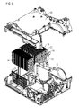
- FIG 2 illustrates a perspective view of the heat pump system for the laundry dryer according to the preferred embodiment of the present invention.
- the compressor 12, the first heat exchanger 14, the expansion device 16 and the second heat exchanger 18 form a refrigerant circuit.
- the refrigerant circuit includes a plurality of refrigerant pipes 22.
- the refrigerant pipes 22 are provided for connecting the compressor 12, the first heat exchanger 14, the expansion device 16 and the second heat exchanger 18.
- first heat exchanger 14 and the second heat exchanger 18 include at least one refrigerant pipe 22 in each case, wherein at least a part of said refrigerant pipe 22 has a serpentine form.
- first heat exchanger 14 and the second heat exchanger 18 include a plurality of metal plates in each case. Said metal plates are very thin.
- the metal plates are made of aluminium.
- the metal plates are arranged in parallel and equally spaced. The metal plates have high heat conductivity. Metal plates are arranges so as to be passed through by laundry drying air.
- FIG 3 illustrates an exploded perspective view of the basement portion 10 for the laundry dryer according to the preferred embodiment of the present invention.
- FIG 3 clarifies the arrangement of the components of the heat pump system.
- the compressor 12 compresses a refrigerant, so that the pressure and temperature of the refrigerant become much higher.
- the compression is an adiabatic compression.
- the first heat exchanger 14, commonly referred as evaporator cools down the drying air stream arriving from a revolving laundry drum 35 (see FIG 9 ), in order to condense the surplus moisture in said drying air stream. Said laundry drum 35 is arranged above the basement portion 10. At the same time, the first heat exchanger 14 heats up the refrigerant. In the expansion device 16 the refrigerant is released and cooled down.
- the second heat exchanger 18, commonly referred as condenser cools down the refrigerant.
- the second heat exchanger 18 heats up again the drying air stream arriving from the first heat exchanger 14.
- the drying air stream is then directed back to the revolving laundry drum 35.
- the temperature of the drying air stream re-entering into the laundry drum again is higher than or equal to that of the drying air stream flowing out of the laundry drum.
- FIG 4 illustrates a detailed perspective view of a pipe joint 24 of the heat pump system for the laundry dryer according to the preferred embodiment of the present invention.
- the pipe joint 24 interconnects two neighboured end pieces of refrigerant pipes 22.
- FIG 4 shows the pipe joint 24 in a connected state.
- the pipe joint 24 is obtained by inserting a narrow end piece 28 of one refrigerant pipe 22 into an enlarged end piece 26 of another refrigerant pipe 22.
- the one end piece 26 is enlarged before connecting the neighboured refrigerant pipes 22.
- the enlarged end piece 26 includes a number of dots 30.
- FIG 5 illustrates a detailed perspective view of the pipe joint 24 of the heat pump system for the laundry dryer according to the preferred embodiment of the present invention.
- the pipe joint 24 is in a disconnected state.
- FIG 5 clarifies that the number of dots 30 are formed in the enlarged end piece 26.
- FIG 6 illustrates a front view and a sectional top view of the pipe joint 24 of the heat pump system for the laundry dryer according to the preferred embodiment of the present invention.
- FIG 6 clarifies the geometric properties of the pipe joint 24, the enlarged end piece 26 and the narrow end piece 28.
- the number of dots 30 is formed in the enlarged end piece 26.
- FIG 7 illustrates an enhanced sectional top view of the pipe joint 24 of the heat pump system for the laundry dryer according to the preferred embodiment of the present invention.
- FIG 7 is the enhanced view of the sectional top view in FIG 6.
- FIG 7 clarifies the structure of the dots 30.
- the enlarged end piece 26 and the narrow end piece 28 have a common symmetry axis 36.
- the enlarged end piece 26 includes a number of dots 30.
- the dots 30 are mechanically formed on the outer surface of said enlarged end piece 26.
- the dots 30 have the effect that the inner diameter of the enlarged end piece 26 is locally smaller than in the remaining enlarged end piece 26.
- the inner diameter of the enlarged end piece 26 substantially corresponds to the outer diameter of the neighboured narrow end piece 28.
- FIG 7 illustrates a detailed view of the dots 30 formed on the outer surface of said enlarged end piece 26.
- the dots 30 are preferably formed by a punching and/or buckling operation on the outer surface of the enlarged end piece 26. Dots 30 are preferably arranged along at least a circumference of the enlarged end piece 26. The dots 30 deform radially and inwardly the enlarged end piece 26 so as to protrude from the inner surface 25 of the enlarged end piece 26 towards the axis 36 of both the enlarged end piece 26 and the narrow end piece. As an option, while enlarging the end piece 26, a portion of said end piece 26 may be prevented from being enlarged, so that this portion remains at its initial diameter. The initial diameter corresponds to the outer diameter of the narrow end piece 28.
- an annular groove or a partially annular groove may be formed on the cylindrical outer surface of the enlarged end piece 26.
- Such groove protrudes inwardly from the inner surface 25 of the enlarged end piece 26 towards the axis 36 of both the enlarged end piece 26 and the narrow end piece.
- the pipe joint 24 mentioned above avoids refrigerant leakages due to wrong alignment between the refrigerant pipes 22 to be connected.
- the above pipe joint 24 avoids accidental release of temporary coupled end pieces 26 and 28 before welding them together. Further, the above pipe joint 24 increases the mechanical strength.
- the above pipe joints 24 improve the efficiency of the heat pump system and simplify its assembling procedure.
- the inventive pipe joint 24 does not require any special tools for keeping the enlarged end piece 26 and the narrow end piece 28 in position during connecting them.
- the pipe joint 24 made according to the invention is preferably provided for connecting the compressor 12 inlet pipe end with the end of the pipe draining refrigerant fluid from the evaporator 14 and for connecting the compressor 12 outlet pipe end with the end of the pipe leading refrigerant fluid to the condenser 18.
- FIG 8 illustrates a perspective view of the laundry dryer 32 according to the preferred embodiment of the present invention.
- the laundry dryer 32 comprises a front portion including a front door 34.
- the laundry drum 35 is arranged behind said front door 34.
- the basement portion 10 is arranged below the laundry drum 35.
- FIG 9 illustrates a detailed perspective view of a lower part of the laundry dryer 32 according to the preferred embodiment of the present invention.
- FIG 9 clarifies the position of the heat pump system inside the basement portion 10.
Landscapes
- Engineering & Computer Science (AREA)
- Textile Engineering (AREA)
- Detail Structures Of Washing Machines And Dryers (AREA)
Abstract
Description
- The present invention relates to a method for assembling a laundry dryer including a heat pump system with a closed refrigerant circuit. Further, the present invention relates to a laundry dryer including a heat pump system with a closed refrigerant circuit. Moreover, the present invention relates to a heat pump system with a closed refrigerant circuit for a laundry dryer.
- Some laundry dryers comprise a heat pump system in order to dry wet clothes. The heat pump system allows that heat energy can be moved from one environment to another, and in either direction. This allows the heat pump system to bring heat into an occupied space, or to take it out of said space. The heat pump system uses an intermediate fluid called refrigerant. Said refrigerant absorbs heat as it vaporizes and releases the heat as it is condensed. In the laundry dryer the moist air coming from the laundry drum passes through the heat exchangers, namely a condenser and an evaporator, and releases the moisture accumulated, wherein the moisture condenses.
- The heat exchangers are composed of very thin metal plates, in particular aluminium plates. Usually, said aluminium plates are arranged in parallel and equally spaced. The metal plates have high heat conductivity. During the drying process the moist air touches the metal plates of the heat pump evaporator and moisture is condensed. The moisture is than driven to a drain pump and finally stored in a tank for being expelled. Laundry drying air further passes through the heat pump condenser for being heated up before being delivered to the drum chamber containing laundry to be dried. The refrigerant flows through special pipes, which crisscross the heat exchangers in order to have the maximum contact with the metal plates of the heat exchangers as well as the moist air. The metal for the refrigerant pipes should be chosen as a good compromise between the costs and the heat conductivity. For this reason welding between pipes of different materials, such as copper and aluminium, are often used.
- Actually the welding process consists basically in inserting a pipe into another pipe and then pouring between them a welding material. This process is easy to perform, but imprecise. In fact, due to a loose space between the pipes to be coupled, there is no guarantee that the pipes themselves remain coaxial. In addition, the temporary insertion of the one pipe end in the other pipe end may be released even by a simple vibration. This could lead to an incomplete welding or avoids the welding, so that refrigerant leakages and losses in the performance of the heat pump system may occur.
- It is an object of the present invention to provide a method for assembling a laundry dryer with a heat pump system and a corresponding laundry dryer, which overcomes the problems relating to the connection of the refrigerant pipes of the refrigerant circuit.
- The object of the present invention is achieved by the method according to claim 1.
- The present invention relates to a method for assembling a laundry dryer including a heat pump system with a closed refrigerant circuit, said method comprises the steps of:
- providing components for the refrigerant circuit, wherein at least two components are coupleable by interconnecting a first end piece and a second end piece of refrigerant pipes,
- enlarging the first end piece of the refrigerant pipe, so that the inner diameter of the first end piece is marginally bigger than the outer diameter of the second end piece,
- deforming the enlarged portion of the first end piece from the outer side, so that the second end piece is coaxially insertable into the first end piece,
- inserting the second end piece into the first end piece, and
- welding together the first end piece and the second end piece.
- The pipe joint between the first end piece and the second end piece avoids refrigerant leakages due to wrong alignment, i.e. centering, between the refrigerant pipes to be connected. Said pipe joint avoids accidental release of the temporary coupled end pieces before welding them together. Further, the pipe joint between the first end piece and the second end piece increases the mechanical strength. These pipe joints improve the efficiency of the heat pump system. The inventive pipe joint between the first end piece and the second end piece does not require any special tools for keeping the enlarged first end piece and the second end piece in position during their connection operation.
- Preferably, deforming the enlarged portion of the first end piece from its outer side comprises forming one or more elements which protrude inwardly from the inner surface of the enlarged portion of said first end piece.
- In particular, the elements protruding inwardly from the inner surface of the enlarged portion of the first end piece comprise a plurality of dots arranged along at least one circumference of the enlarged portion of the first end piece.
- Optionally, at least one predetermined portion of the first end piece is prevented from being enlarged, so that at least this portion remains at its initial diameter.
- Alternatively or additionally, at least one circumferential groove is formed on the outer surface of the enlarged portion of the first end piece, so that the inserted second end piece is firmly kept inside the enlarged portion of the first end piece.
- Preferably, the first end piece and the second end piece are welded together by pouring a welding material between said first end piece and second end piece.
- In particular, the first end piece and the second end piece are welded together by pouring the welding material between a circumferential inner side of the enlarged portion of the first end piece and a circumferential outer side of the second end piece.
- Further, the object of the present invention is achieved by the laundry dryer according to claim 8.
- The present invention relates to a laundry dryer including a heat pump system with a closed refrigerant circuit, wherein:
- the refrigerant circuit comprises a number of components, wherein at least two components are coupled by interconnecting a first end piece and a second end piece of refrigerant pipes,
- the first end piece of the refrigerant pipe is enlarged, so that the inner diameter of the first end piece is marginally bigger than the outer diameter of the second end piece,
- the enlarged portion of the first end piece is deformed from the outer side, so that the second end piece is coaxially inserted into the first end piece, and
- the first end piece and the second end piece are welded together.
- In particular, the enlarged portion of the first end piece comprises one or more elements which protrude inwardly from the inner surface of the enlarged portion of said first end piece.
- Preferably, the elements protruding inwardly from the inner surface of the enlarged portion of said first end piece comprise a plurality of dots arranged along at least one circumference of the enlarged portion of the first end piece.
- As an option, at least one predetermined portion of the first end piece is remained at its initial diameter.
- Alternatively or additionally, at least one circumferential groove is formed on the outer surface of the enlarged portion of the first end piece, so that the inserted second end piece is firmly kept inside the enlarged portion of the first end piece.
- Preferably, the first end piece and the second end piece are welded together, wherein a welding material has been poured between said first end piece and second end piece.
- In particular, the first end piece and the second end piece are welded together by pouring the welding material between a circumferential inner side of the enlarged portion of the first end piece and a circumferential outer side of the second end piece.
- At last the present invention relates to a heat pump system with a closed refrigerant circuit for a laundry dryer, wherein the heat pump system is provided for a laundry dryer mentioned above.
- Novel and inventive features believed to be the characteristic of the present invention are set forth in the appended claims.
- The invention will be described in further detail with reference to the drawings, in which
- FIG 1
- illustrates a perspective view of a basement portion for a laundry dryer according to a preferred embodiment of the present invention,
- FIG 2
- illustrates a perspective view of a heat pump system for the laundry dryer according to the preferred embodiment of the present invention,
- FIG 3
- illustrates an exploded perspective view of the basement portion for the laundry dryer according to the preferred embodiment of the present invention,
- FIG 4
- illustrates a detailed perspective view of a pipe joint of the heat pump system for the laundry dryer according to the preferred embodiment of the present invention,
- FIG 5
- illustrates a detailed perspective view of the pipe joint of the heat pump system for the laundry dryer according to the preferred embodiment of the present invention,
- FIG 6
- illustrates a front view and a sectional top view of the pipe joint of the heat pump system for the laundry dryer according to the preferred embodiment of the present invention,
- FIG 7
- illustrates an enhanced sectional top view of the pipe joint of the heat pump system for the laundry dryer according to the preferred embodiment of the present invention,
- FIG 8
- illustrates a perspective view of the laundry dryer according to the preferred embodiment of the present invention, and
- FIG 9
- illustrates a detailed perspective view of a lower part of the laundry dryer according to the preferred embodiment of the present invention.
-
FIG 1 illustrates a perspective view of abasement portion 10 for a laundry dryer according to a preferred embodiment of the present invention. A heat pump system is arranged in saidbasement portion 10. - The heat pump system includes a
compressor 12, afirst heat exchanger 14, i.e. a refrigerant evaporator, asecond heat exchanger 18, i.e. a refrigerant condenser, and anexpansion device 16 arranged in the refrigerant pipe line leading the refrigerant from thecondenser 18 to theevaporator 14. Thefirst heat exchanger 14 andsecond heat exchanger 18 are air-to-refrigerant heat exchangers. InFIG 1 thefirst heat exchanger 14 and thesecond heat exchanger 18 are covered by abasement casing 20.Such casing 20 forms a portion of a laundry drying air path that conveys air towards a rotatable drum chamber where laundry to be dried is contained. -
FIG 2 illustrates a perspective view of the heat pump system for the laundry dryer according to the preferred embodiment of the present invention. Thecompressor 12, thefirst heat exchanger 14, theexpansion device 16 and thesecond heat exchanger 18 form a refrigerant circuit. The refrigerant circuit includes a plurality ofrefrigerant pipes 22. Therefrigerant pipes 22 are provided for connecting thecompressor 12, thefirst heat exchanger 14, theexpansion device 16 and thesecond heat exchanger 18. - Further, the
first heat exchanger 14 and thesecond heat exchanger 18 include at least onerefrigerant pipe 22 in each case, wherein at least a part of saidrefrigerant pipe 22 has a serpentine form. Moreover, thefirst heat exchanger 14 and thesecond heat exchanger 18 include a plurality of metal plates in each case. Said metal plates are very thin. In particular, the metal plates are made of aluminium. Preferably, the metal plates are arranged in parallel and equally spaced. The metal plates have high heat conductivity. Metal plates are arranges so as to be passed through by laundry drying air. -
FIG 3 illustrates an exploded perspective view of thebasement portion 10 for the laundry dryer according to the preferred embodiment of the present invention.FIG 3 clarifies the arrangement of the components of the heat pump system. - The
compressor 12 compresses a refrigerant, so that the pressure and temperature of the refrigerant become much higher. For example, the compression is an adiabatic compression. Thefirst heat exchanger 14, commonly referred as evaporator, cools down the drying air stream arriving from a revolving laundry drum 35 (seeFIG 9 ), in order to condense the surplus moisture in said drying air stream. Saidlaundry drum 35 is arranged above thebasement portion 10. At the same time, thefirst heat exchanger 14 heats up the refrigerant. In theexpansion device 16 the refrigerant is released and cooled down. Thesecond heat exchanger 18, commonly referred as condenser, cools down the refrigerant. At the same time, thesecond heat exchanger 18 heats up again the drying air stream arriving from thefirst heat exchanger 14. The drying air stream is then directed back to the revolvinglaundry drum 35. The temperature of the drying air stream re-entering into the laundry drum again is higher than or equal to that of the drying air stream flowing out of the laundry drum. -
FIG 4 illustrates a detailed perspective view of apipe joint 24 of the heat pump system for the laundry dryer according to the preferred embodiment of the present invention. The pipe joint 24 interconnects two neighboured end pieces ofrefrigerant pipes 22.FIG 4 shows the pipe joint 24 in a connected state. - The pipe joint 24 is obtained by inserting a
narrow end piece 28 of onerefrigerant pipe 22 into anenlarged end piece 26 of anotherrefrigerant pipe 22. The oneend piece 26 is enlarged before connecting the neighbouredrefrigerant pipes 22. Theenlarged end piece 26 includes a number ofdots 30. -
FIG 5 illustrates a detailed perspective view of thepipe joint 24 of the heat pump system for the laundry dryer according to the preferred embodiment of the present invention. InFIG 5 , the pipe joint 24 is in a disconnected state.FIG 5 clarifies that the number ofdots 30 are formed in theenlarged end piece 26. -
FIG 6 illustrates a front view and a sectional top view of thepipe joint 24 of the heat pump system for the laundry dryer according to the preferred embodiment of the present invention.FIG 6 clarifies the geometric properties of the pipe joint 24, theenlarged end piece 26 and thenarrow end piece 28. The number ofdots 30 is formed in theenlarged end piece 26. -
FIG 7 illustrates an enhanced sectional top view of thepipe joint 24 of the heat pump system for the laundry dryer according to the preferred embodiment of the present invention.FIG 7 is the enhanced view of the sectional top view inFIG 6. FIG 7 clarifies the structure of thedots 30. Theenlarged end piece 26 and thenarrow end piece 28 have acommon symmetry axis 36. - In
FIG 7 theenlarged end piece 26 includes a number ofdots 30. Thedots 30 are mechanically formed on the outer surface of saidenlarged end piece 26. Thedots 30 have the effect that the inner diameter of theenlarged end piece 26 is locally smaller than in the remainingenlarged end piece 26. At thedots 30 the inner diameter of theenlarged end piece 26 substantially corresponds to the outer diameter of the neighbourednarrow end piece 28.FIG 7 illustrates a detailed view of thedots 30 formed on the outer surface of saidenlarged end piece 26. - The
dots 30 are preferably formed by a punching and/or buckling operation on the outer surface of theenlarged end piece 26.Dots 30 are preferably arranged along at least a circumference of theenlarged end piece 26. Thedots 30 deform radially and inwardly theenlarged end piece 26 so as to protrude from theinner surface 25 of theenlarged end piece 26 towards theaxis 36 of both theenlarged end piece 26 and the narrow end piece. As an option, while enlarging theend piece 26, a portion of saidend piece 26 may be prevented from being enlarged, so that this portion remains at its initial diameter. The initial diameter corresponds to the outer diameter of thenarrow end piece 28. - Instead of the
dots 30 or additionally, an annular groove or a partially annular groove, may be formed on the cylindrical outer surface of theenlarged end piece 26. Such groove protrudes inwardly from theinner surface 25 of theenlarged end piece 26 towards theaxis 36 of both theenlarged end piece 26 and the narrow end piece. Once thenarrow end piece 28 has been inserted into theenlarged end piece 26, thenarrow end piece 28 and the elements protruding inwardly from theinner surface 25 of theenlarged end piece 26 interfere each other such that thenarrow end piece 28 is firmly kept in theenlarged end piece 26 ensuring that coupled pipe ends remain coaxial. In this way, when the welding material is poured between the two neighbouredpipes 22 it distributes regularly between them. This guarantees a perfect sealing and high mechanical strength. - The pipe joint 24 mentioned above avoids refrigerant leakages due to wrong alignment between the
refrigerant pipes 22 to be connected. The above pipe joint 24 avoids accidental release of temporary coupledend pieces enlarged end piece 26 and thenarrow end piece 28 in position during connecting them. - The pipe joint 24 made according to the invention is preferably provided for connecting the
compressor 12 inlet pipe end with the end of the pipe draining refrigerant fluid from theevaporator 14 and for connecting thecompressor 12 outlet pipe end with the end of the pipe leading refrigerant fluid to thecondenser 18. -
FIG 8 illustrates a perspective view of thelaundry dryer 32 according to the preferred embodiment of the present invention. Thelaundry dryer 32 comprises a front portion including afront door 34. Thelaundry drum 35 is arranged behind saidfront door 34. Thebasement portion 10 is arranged below thelaundry drum 35. -
FIG 9 illustrates a detailed perspective view of a lower part of thelaundry dryer 32 according to the preferred embodiment of the present invention.FIG 9 clarifies the position of the heat pump system inside thebasement portion 10. - Although illustrative embodiments of the present invention have been described herein with reference to the accompanying drawings, it is to be understood that the present invention is not limited to those precise embodiments, and that various other changes and modifications may be affected therein by one skilled in the art without departing from the scope of the invention as claimed. All such changes and modifications are intended to be included within the scope of the invention as defined by the appended claims.
-
- 10
- basement portion
- 12
- compressor
- 14
- first heat exchanger
- 16
- expansion device
- 18
- second heat exchanger
- 20
- basement casing
- 22
- refrigerant pipe
- 24
- pipe joint
- 25
- inner surface
- 26
- enlarged end piece
- 28
- narrow end piece
- 30
- dot
- 32
- laundry dryer
- 34
- front door
- 35
- laundry drum
- 36
- symmetry axis
Claims (15)
- A method for assembling a laundry dryer (32) including a heat pump system with a closed refrigerant circuit, said method comprises the steps of:- providing components (12, 14, 16, 18) for the refrigerant circuit, wherein at least two components (12, 14, 16, 18) are coupleable by interconnecting a first end piece (26) and a second end piece (28) of refrigerant pipes (22),- enlarging the first end piece (26) of the refrigerant pipe (22), so that the inner diameter of the first end piece (26) is marginally bigger than the outer diameter of the second end piece (28),- deforming the enlarged portion of the first end piece (26) from the outer side, so that the second end piece (28) is coaxially insertable into the first end piece (28),- inserting the second end piece (28) into the first end piece (28), and- welding together the first end piece (26) and the second end piece (28).
- The method according to claim 1,
characterized in that
deforming the enlarged portion of the first end piece (26) from the outer side comprises forming one or more elements (30) which protrude inwardly from the inner surface of the enlarged portion of said first end piece (26). - The method according to claim 2,
characterized in that
said elements (30) comprise a plurality of dots (30) arranged along at least one circumference of the enlarged portion of the first end piece (26). - The method according to any one of the preceding claims,
characterized in that
at least one predetermined portion of the first end piece (26) is prevented from being enlarged, so that at least this portion remains at its initial diameter. - The method according to any one of the preceding claims,
characterized in that
at least one circumferential groove is formed on the outer surface of the enlarged portion of the first end piece (26), so that the inserted second end piece (28) is firmly kept inside the enlarged portion of the first end piece (26). - The method according to any one of the preceding claims,
characterized in that
the first end piece (26) and the second end piece (28) are welded together by pouring a welding material between said first end piece (26) and second end piece (28). - The method according to claim 6,
characterized in that
the first end piece (26) and the second end piece (28) are welded together by pouring the welding material between a circumferential inner side of the enlarged portion of the first end piece (26) and a circumferential outer side of the second end piece (28). - A laundry dryer (32) including a heat pump system with a closed refrigerant circuit, wherein:- the refrigerant circuit comprises a number of components (12, 14, 16, 18), wherein at least two components (12, 14, 16, 18) are coupled by interconnecting a first end piece (26) and a second end piece (28) of refrigerant pipes (22),- the first end piece (26) of the refrigerant pipe (22) is enlarged, so that the inner diameter of the first end piece (26) is marginally bigger than the outer diameter of the second end piece (28),- the enlarged portion of the first end piece (26) is deformed from the outer side, so that the second end piece (28) is coaxially inserted into the first end piece (28), and- the first end piece (26) and the second end piece (28) are welded together.
- The laundry dryer according to claim 8,
characterized in that
the enlarged portion of the first end piece (26) comprises one or more elements (30) which protrude inwardly from the inner surface of the enlarged portion of said first end piece (26). - The laundry dryer according to claim 9,
characterized in that
said elements (30) comprise a plurality of dots (30) arranged along at least one circumference of the enlarged portion of the first end piece (26). - The laundry dryer according to any one of the claims 8 to 10,
characterized in that
at least one predetermined portion of the first end piece (26) is remained at its initial diameter. - The laundry dryer according to any one of the claims 8 to 11,
characterized in that
at least one circumferential groove is formed on the outer surface of the enlarged portion of the first end piece (26), so that the inserted second end piece (28) is firmly kept inside the enlarged portion of the first end piece (26). - The laundry dryer according to any one of the claims 8 to 12,
characterized in that
the first end piece (26) and the second end piece (28) are welded together, wherein a welding material has been poured between said first end piece (26) and second end piece (28). - The laundry dryer according to claim 13,
characterized in that
the first end piece (26) and the second end piece (28) are welded together by pouring the welding material between a circumferential inner side of the enlarged portion of the first end piece (26) and a circumferential outer side of the second end piece (28). - A heat pump system with a closed refrigerant circuit for a laundry dryer,
characterized in that
the heat pump system is provided for a laundry dryer (32) according to any one of the claims 8 to 14.
Priority Applications (3)
| Application Number | Priority Date | Filing Date | Title |
|---|---|---|---|
| PL13161827T PL2784207T3 (en) | 2013-03-29 | 2013-03-29 | A method for assembling a laundry dryer including a heat pump system with a closed refrigerant circuit and a heat pump laundry dryer with a closed refrigerant circuit |
| EP13161827.4A EP2784207B1 (en) | 2013-03-29 | 2013-03-29 | A method for assembling a laundry dryer including a heat pump system with a closed refrigerant circuit and a heat pump laundry dryer with a closed refrigerant circuit |
| CN201410126108.5A CN104074036A (en) | 2013-03-29 | 2014-03-31 | A method for assembling a laundry dryer including a heat pump system with a closed refrigerant circuit and a heat pump laundry dryer with a closed refrigerant circuit |
Applications Claiming Priority (1)
| Application Number | Priority Date | Filing Date | Title |
|---|---|---|---|
| EP13161827.4A EP2784207B1 (en) | 2013-03-29 | 2013-03-29 | A method for assembling a laundry dryer including a heat pump system with a closed refrigerant circuit and a heat pump laundry dryer with a closed refrigerant circuit |
Publications (2)
| Publication Number | Publication Date |
|---|---|
| EP2784207A1 true EP2784207A1 (en) | 2014-10-01 |
| EP2784207B1 EP2784207B1 (en) | 2017-02-01 |
Family
ID=48047853
Family Applications (1)
| Application Number | Title | Priority Date | Filing Date |
|---|---|---|---|
| EP13161827.4A Not-in-force EP2784207B1 (en) | 2013-03-29 | 2013-03-29 | A method for assembling a laundry dryer including a heat pump system with a closed refrigerant circuit and a heat pump laundry dryer with a closed refrigerant circuit |
Country Status (3)
| Country | Link |
|---|---|
| EP (1) | EP2784207B1 (en) |
| CN (1) | CN104074036A (en) |
| PL (1) | PL2784207T3 (en) |
Cited By (5)
| Publication number | Priority date | Publication date | Assignee | Title |
|---|---|---|---|---|
| US20130305553A1 (en) * | 2012-05-15 | 2013-11-21 | Seonil Heo | Clothes dryer |
| US20160362829A1 (en) * | 2015-06-09 | 2016-12-15 | Lg Electronics Inc. | Device for drying laundry |
| WO2023073749A1 (en) * | 2021-10-25 | 2023-05-04 | 三菱電機株式会社 | Heat exchanger |
| EP4332489A4 (en) * | 2021-04-28 | 2024-10-02 | Daikin Industries, Ltd. | Pipe connection structure and refrigeration cycle device |
| JP7797718B1 (en) * | 2025-02-04 | 2026-01-13 | ボッシュホームコンフォートジャパン株式会社 | air conditioner |
Families Citing this family (2)
| Publication number | Priority date | Publication date | Assignee | Title |
|---|---|---|---|---|
| CN111021015B (en) * | 2019-12-17 | 2022-04-29 | 无锡小天鹅电器有限公司 | Clothes treatment equipment and base assembly thereof |
| CN114753087B (en) * | 2021-11-30 | 2026-01-16 | 珠海格力电器股份有限公司 | Clothing processing apparatus with heat pump stoving function |
Citations (6)
| Publication number | Priority date | Publication date | Assignee | Title |
|---|---|---|---|---|
| US3347728A (en) * | 1964-07-29 | 1967-10-17 | Gen Motors Corp | Method for forming joints in tubes |
| US6654995B1 (en) * | 2000-10-16 | 2003-12-02 | General Motors Corporation | Method for joining tubular members |
| JP2007187413A (en) * | 2006-01-16 | 2007-07-26 | Sanyo Electric Co Ltd | Heat exchanger |
| JP2008005898A (en) * | 2006-06-27 | 2008-01-17 | Toshiba Corp | Clothes dryer |
| US20080120844A1 (en) * | 2006-10-31 | 2008-05-29 | Gm Global Technology Operations, Inc. | Method for manufacture of shaped tubular part |
| JP2010227969A (en) * | 2009-03-27 | 2010-10-14 | Panasonic Corp | Aluminum tube connection structure, connection method and heat exchanger |
Family Cites Families (4)
| Publication number | Priority date | Publication date | Assignee | Title |
|---|---|---|---|---|
| JPS5257557A (en) * | 1975-11-07 | 1977-05-12 | Hitachi Ltd | Heat exchanger |
| KR101169753B1 (en) * | 2010-10-06 | 2012-07-31 | 주식회사 고산 | Header pipe connector of the heat exchanger |
| CN202158790U (en) * | 2011-05-26 | 2012-03-07 | 大连三洋冷链有限公司 | High pressure resistance copper pipe fin type heat exchanger |
| CN202372046U (en) * | 2011-11-17 | 2012-08-08 | 威海友邦汽车零部件制造有限公司 | Pipe connecting structure |
-
2013
- 2013-03-29 EP EP13161827.4A patent/EP2784207B1/en not_active Not-in-force
- 2013-03-29 PL PL13161827T patent/PL2784207T3/en unknown
-
2014
- 2014-03-31 CN CN201410126108.5A patent/CN104074036A/en active Pending
Patent Citations (6)
| Publication number | Priority date | Publication date | Assignee | Title |
|---|---|---|---|---|
| US3347728A (en) * | 1964-07-29 | 1967-10-17 | Gen Motors Corp | Method for forming joints in tubes |
| US6654995B1 (en) * | 2000-10-16 | 2003-12-02 | General Motors Corporation | Method for joining tubular members |
| JP2007187413A (en) * | 2006-01-16 | 2007-07-26 | Sanyo Electric Co Ltd | Heat exchanger |
| JP2008005898A (en) * | 2006-06-27 | 2008-01-17 | Toshiba Corp | Clothes dryer |
| US20080120844A1 (en) * | 2006-10-31 | 2008-05-29 | Gm Global Technology Operations, Inc. | Method for manufacture of shaped tubular part |
| JP2010227969A (en) * | 2009-03-27 | 2010-10-14 | Panasonic Corp | Aluminum tube connection structure, connection method and heat exchanger |
Cited By (7)
| Publication number | Priority date | Publication date | Assignee | Title |
|---|---|---|---|---|
| US20130305553A1 (en) * | 2012-05-15 | 2013-11-21 | Seonil Heo | Clothes dryer |
| US9200841B2 (en) * | 2012-05-15 | 2015-12-01 | Lg Electronics Inc. | Clothes dryer |
| US20160362829A1 (en) * | 2015-06-09 | 2016-12-15 | Lg Electronics Inc. | Device for drying laundry |
| KR20160144641A (en) * | 2015-06-09 | 2016-12-19 | 엘지전자 주식회사 | Device for drying laundry |
| EP4332489A4 (en) * | 2021-04-28 | 2024-10-02 | Daikin Industries, Ltd. | Pipe connection structure and refrigeration cycle device |
| WO2023073749A1 (en) * | 2021-10-25 | 2023-05-04 | 三菱電機株式会社 | Heat exchanger |
| JP7797718B1 (en) * | 2025-02-04 | 2026-01-13 | ボッシュホームコンフォートジャパン株式会社 | air conditioner |
Also Published As
| Publication number | Publication date |
|---|---|
| PL2784207T3 (en) | 2017-07-31 |
| CN104074036A (en) | 2014-10-01 |
| EP2784207B1 (en) | 2017-02-01 |
Similar Documents
| Publication | Publication Date | Title |
|---|---|---|
| EP2784207B1 (en) | A method for assembling a laundry dryer including a heat pump system with a closed refrigerant circuit and a heat pump laundry dryer with a closed refrigerant circuit | |
| EP2385169A1 (en) | A laundry machine with heat pump system and a method for operating the laundry machine | |
| KR102077565B1 (en) | Shell and tube type heat exchanger and Manufacturing method of the same | |
| JP5422881B2 (en) | Dehumidifier | |
| US9709306B2 (en) | Suction pipe and capillary tube arrangement for a refrigerator | |
| EP2761078B1 (en) | Heat pump laundry dryer | |
| JP6765528B2 (en) | Heat exchanger, refrigeration cycle device and air conditioner | |
| CN105705899A (en) | Heat pump for a household appliance | |
| US9080795B2 (en) | Air conditioning system | |
| CN104204335A (en) | Heat pump for a clothes treatment appliance, and clothes treatment appliance comprising such heat pump | |
| CN113390135A (en) | Heat transfer module for dehumidifier and manufacturing method thereof | |
| KR102361127B1 (en) | Device for drying laundry | |
| JP6574630B2 (en) | Double tube heat exchanger | |
| US20140027101A1 (en) | Heat exchanger | |
| KR102097061B1 (en) | Heat exchanger and manufacturing method thereof | |
| JP2012130473A (en) | Dehumidifying and heating apparatus and clothes dryer including the same | |
| CN116949777A (en) | Clothes dryer | |
| WO2024087687A1 (en) | Heat exchanger structure and clothes treatment device | |
| CN104755826A (en) | High pressure containment vessel | |
| KR101192301B1 (en) | Condenser integrated with receiver dryer | |
| JP2016095039A (en) | Refrigeration cycle equipment | |
| JP6440867B2 (en) | HEAT EXCHANGER, AIR CONDITIONER EQUIPPED WITH THE SAME, AND METHOD FOR PRODUCING HEAT EXCHANGER | |
| JP4665801B2 (en) | Air conditioner | |
| JP4702411B2 (en) | Evaporator | |
| EP3896210B1 (en) | A laundry treating appliance having a heat pump system |
Legal Events
| Date | Code | Title | Description |
|---|---|---|---|
| 17P | Request for examination filed |
Effective date: 20130329 |
|
| AK | Designated contracting states |
Kind code of ref document: A1 Designated state(s): AL AT BE BG CH CY CZ DE DK EE ES FI FR GB GR HR HU IE IS IT LI LT LU LV MC MK MT NL NO PL PT RO RS SE SI SK SM TR |
|
| AX | Request for extension of the european patent |
Extension state: BA ME |
|
| PUAI | Public reference made under article 153(3) epc to a published international application that has entered the european phase |
Free format text: ORIGINAL CODE: 0009012 |
|
| R17P | Request for examination filed (corrected) |
Effective date: 20150401 |
|
| RBV | Designated contracting states (corrected) |
Designated state(s): AL AT BE BG CH CY CZ DE DK EE ES FI FR GB GR HR HU IE IS IT LI LT LU LV MC MK MT NL NO PL PT RO RS SE SI SK SM TR |
|
| 17Q | First examination report despatched |
Effective date: 20150908 |
|
| GRAP | Despatch of communication of intention to grant a patent |
Free format text: ORIGINAL CODE: EPIDOSNIGR1 |
|
| INTG | Intention to grant announced |
Effective date: 20160915 |
|
| GRAS | Grant fee paid |
Free format text: ORIGINAL CODE: EPIDOSNIGR3 |
|
| GRAA | (expected) grant |
Free format text: ORIGINAL CODE: 0009210 |
|
| AK | Designated contracting states |
Kind code of ref document: B1 Designated state(s): AL AT BE BG CH CY CZ DE DK EE ES FI FR GB GR HR HU IE IS IT LI LT LU LV MC MK MT NL NO PL PT RO RS SE SI SK SM TR |
|
| REG | Reference to a national code |
Ref country code: GB Ref legal event code: FG4D |
|
| REG | Reference to a national code |
Ref country code: CH Ref legal event code: EP Ref country code: AT Ref legal event code: REF Ref document number: 865710 Country of ref document: AT Kind code of ref document: T Effective date: 20170215 |
|
| REG | Reference to a national code |
Ref country code: IE Ref legal event code: FG4D |
|
| REG | Reference to a national code |
Ref country code: DE Ref legal event code: R096 Ref document number: 602013016909 Country of ref document: DE |
|
| REG | Reference to a national code |
Ref country code: NL Ref legal event code: MP Effective date: 20170201 |
|
| REG | Reference to a national code |
Ref country code: LT Ref legal event code: MG4D |
|
| REG | Reference to a national code |
Ref country code: AT Ref legal event code: MK05 Ref document number: 865710 Country of ref document: AT Kind code of ref document: T Effective date: 20170201 |
|
| PG25 | Lapsed in a contracting state [announced via postgrant information from national office to epo] |
Ref country code: IS Free format text: LAPSE BECAUSE OF FAILURE TO SUBMIT A TRANSLATION OF THE DESCRIPTION OR TO PAY THE FEE WITHIN THE PRESCRIBED TIME-LIMIT Effective date: 20170601 Ref country code: FI Free format text: LAPSE BECAUSE OF FAILURE TO SUBMIT A TRANSLATION OF THE DESCRIPTION OR TO PAY THE FEE WITHIN THE PRESCRIBED TIME-LIMIT Effective date: 20170201 Ref country code: HR Free format text: LAPSE BECAUSE OF FAILURE TO SUBMIT A TRANSLATION OF THE DESCRIPTION OR TO PAY THE FEE WITHIN THE PRESCRIBED TIME-LIMIT Effective date: 20170201 Ref country code: GR Free format text: LAPSE BECAUSE OF FAILURE TO SUBMIT A TRANSLATION OF THE DESCRIPTION OR TO PAY THE FEE WITHIN THE PRESCRIBED TIME-LIMIT Effective date: 20170502 Ref country code: NO Free format text: LAPSE BECAUSE OF FAILURE TO SUBMIT A TRANSLATION OF THE DESCRIPTION OR TO PAY THE FEE WITHIN THE PRESCRIBED TIME-LIMIT Effective date: 20170501 Ref country code: LT Free format text: LAPSE BECAUSE OF FAILURE TO SUBMIT A TRANSLATION OF THE DESCRIPTION OR TO PAY THE FEE WITHIN THE PRESCRIBED TIME-LIMIT Effective date: 20170201 |
|
| PG25 | Lapsed in a contracting state [announced via postgrant information from national office to epo] |
Ref country code: LV Free format text: LAPSE BECAUSE OF FAILURE TO SUBMIT A TRANSLATION OF THE DESCRIPTION OR TO PAY THE FEE WITHIN THE PRESCRIBED TIME-LIMIT Effective date: 20170201 Ref country code: ES Free format text: LAPSE BECAUSE OF FAILURE TO SUBMIT A TRANSLATION OF THE DESCRIPTION OR TO PAY THE FEE WITHIN THE PRESCRIBED TIME-LIMIT Effective date: 20170201 Ref country code: BG Free format text: LAPSE BECAUSE OF FAILURE TO SUBMIT A TRANSLATION OF THE DESCRIPTION OR TO PAY THE FEE WITHIN THE PRESCRIBED TIME-LIMIT Effective date: 20170501 Ref country code: NL Free format text: LAPSE BECAUSE OF NON-PAYMENT OF DUE FEES Effective date: 20170201 Ref country code: AT Free format text: LAPSE BECAUSE OF FAILURE TO SUBMIT A TRANSLATION OF THE DESCRIPTION OR TO PAY THE FEE WITHIN THE PRESCRIBED TIME-LIMIT Effective date: 20170201 Ref country code: PT Free format text: LAPSE BECAUSE OF FAILURE TO SUBMIT A TRANSLATION OF THE DESCRIPTION OR TO PAY THE FEE WITHIN THE PRESCRIBED TIME-LIMIT Effective date: 20170601 Ref country code: RS Free format text: LAPSE BECAUSE OF FAILURE TO SUBMIT A TRANSLATION OF THE DESCRIPTION OR TO PAY THE FEE WITHIN THE PRESCRIBED TIME-LIMIT Effective date: 20170201 Ref country code: SE Free format text: LAPSE BECAUSE OF FAILURE TO SUBMIT A TRANSLATION OF THE DESCRIPTION OR TO PAY THE FEE WITHIN THE PRESCRIBED TIME-LIMIT Effective date: 20170201 |
|
| PG25 | Lapsed in a contracting state [announced via postgrant information from national office to epo] |
Ref country code: SK Free format text: LAPSE BECAUSE OF FAILURE TO SUBMIT A TRANSLATION OF THE DESCRIPTION OR TO PAY THE FEE WITHIN THE PRESCRIBED TIME-LIMIT Effective date: 20170201 Ref country code: CZ Free format text: LAPSE BECAUSE OF FAILURE TO SUBMIT A TRANSLATION OF THE DESCRIPTION OR TO PAY THE FEE WITHIN THE PRESCRIBED TIME-LIMIT Effective date: 20170201 Ref country code: EE Free format text: LAPSE BECAUSE OF FAILURE TO SUBMIT A TRANSLATION OF THE DESCRIPTION OR TO PAY THE FEE WITHIN THE PRESCRIBED TIME-LIMIT Effective date: 20170201 Ref country code: RO Free format text: LAPSE BECAUSE OF FAILURE TO SUBMIT A TRANSLATION OF THE DESCRIPTION OR TO PAY THE FEE WITHIN THE PRESCRIBED TIME-LIMIT Effective date: 20170201 |
|
| REG | Reference to a national code |
Ref country code: CH Ref legal event code: PL |
|
| REG | Reference to a national code |
Ref country code: DE Ref legal event code: R097 Ref document number: 602013016909 Country of ref document: DE |
|
| PG25 | Lapsed in a contracting state [announced via postgrant information from national office to epo] |
Ref country code: MC Free format text: LAPSE BECAUSE OF FAILURE TO SUBMIT A TRANSLATION OF THE DESCRIPTION OR TO PAY THE FEE WITHIN THE PRESCRIBED TIME-LIMIT Effective date: 20170201 Ref country code: DK Free format text: LAPSE BECAUSE OF FAILURE TO SUBMIT A TRANSLATION OF THE DESCRIPTION OR TO PAY THE FEE WITHIN THE PRESCRIBED TIME-LIMIT Effective date: 20170201 Ref country code: SM Free format text: LAPSE BECAUSE OF FAILURE TO SUBMIT A TRANSLATION OF THE DESCRIPTION OR TO PAY THE FEE WITHIN THE PRESCRIBED TIME-LIMIT Effective date: 20170201 |
|
| PLBE | No opposition filed within time limit |
Free format text: ORIGINAL CODE: 0009261 |
|
| STAA | Information on the status of an ep patent application or granted ep patent |
Free format text: STATUS: NO OPPOSITION FILED WITHIN TIME LIMIT |
|
| REG | Reference to a national code |
Ref country code: IE Ref legal event code: MM4A |
|
| REG | Reference to a national code |
Ref country code: FR Ref legal event code: ST Effective date: 20171130 |
|
| 26N | No opposition filed |
Effective date: 20171103 |
|
| GBPC | Gb: european patent ceased through non-payment of renewal fee |
Effective date: 20170501 |
|
| PG25 | Lapsed in a contracting state [announced via postgrant information from national office to epo] |
Ref country code: FR Free format text: LAPSE BECAUSE OF NON-PAYMENT OF DUE FEES Effective date: 20170403 Ref country code: LU Free format text: LAPSE BECAUSE OF NON-PAYMENT OF DUE FEES Effective date: 20170329 |
|
| PG25 | Lapsed in a contracting state [announced via postgrant information from national office to epo] |
Ref country code: CH Free format text: LAPSE BECAUSE OF NON-PAYMENT OF DUE FEES Effective date: 20170331 Ref country code: IE Free format text: LAPSE BECAUSE OF NON-PAYMENT OF DUE FEES Effective date: 20170329 Ref country code: SI Free format text: LAPSE BECAUSE OF FAILURE TO SUBMIT A TRANSLATION OF THE DESCRIPTION OR TO PAY THE FEE WITHIN THE PRESCRIBED TIME-LIMIT Effective date: 20170201 Ref country code: LI Free format text: LAPSE BECAUSE OF NON-PAYMENT OF DUE FEES Effective date: 20170331 |
|
| REG | Reference to a national code |
Ref country code: BE Ref legal event code: MM Effective date: 20170331 |
|
| PG25 | Lapsed in a contracting state [announced via postgrant information from national office to epo] |
Ref country code: GB Free format text: LAPSE BECAUSE OF NON-PAYMENT OF DUE FEES Effective date: 20170501 |
|
| PG25 | Lapsed in a contracting state [announced via postgrant information from national office to epo] |
Ref country code: BE Free format text: LAPSE BECAUSE OF NON-PAYMENT OF DUE FEES Effective date: 20170331 |
|
| PG25 | Lapsed in a contracting state [announced via postgrant information from national office to epo] |
Ref country code: MT Free format text: LAPSE BECAUSE OF NON-PAYMENT OF DUE FEES Effective date: 20170329 |
|
| PG25 | Lapsed in a contracting state [announced via postgrant information from national office to epo] |
Ref country code: HU Free format text: LAPSE BECAUSE OF FAILURE TO SUBMIT A TRANSLATION OF THE DESCRIPTION OR TO PAY THE FEE WITHIN THE PRESCRIBED TIME-LIMIT; INVALID AB INITIO Effective date: 20130329 |
|
| PG25 | Lapsed in a contracting state [announced via postgrant information from national office to epo] |
Ref country code: CY Free format text: LAPSE BECAUSE OF FAILURE TO SUBMIT A TRANSLATION OF THE DESCRIPTION OR TO PAY THE FEE WITHIN THE PRESCRIBED TIME-LIMIT Effective date: 20170201 |
|
| PG25 | Lapsed in a contracting state [announced via postgrant information from national office to epo] |
Ref country code: MK Free format text: LAPSE BECAUSE OF FAILURE TO SUBMIT A TRANSLATION OF THE DESCRIPTION OR TO PAY THE FEE WITHIN THE PRESCRIBED TIME-LIMIT Effective date: 20170201 |
|
| PG25 | Lapsed in a contracting state [announced via postgrant information from national office to epo] |
Ref country code: TR Free format text: LAPSE BECAUSE OF FAILURE TO SUBMIT A TRANSLATION OF THE DESCRIPTION OR TO PAY THE FEE WITHIN THE PRESCRIBED TIME-LIMIT Effective date: 20170201 |
|
| PG25 | Lapsed in a contracting state [announced via postgrant information from national office to epo] |
Ref country code: AL Free format text: LAPSE BECAUSE OF FAILURE TO SUBMIT A TRANSLATION OF THE DESCRIPTION OR TO PAY THE FEE WITHIN THE PRESCRIBED TIME-LIMIT Effective date: 20170201 |
|
| PGFP | Annual fee paid to national office [announced via postgrant information from national office to epo] |
Ref country code: PL Payment date: 20230302 Year of fee payment: 11 Ref country code: IT Payment date: 20230321 Year of fee payment: 11 Ref country code: DE Payment date: 20230328 Year of fee payment: 11 |
|
| P01 | Opt-out of the competence of the unified patent court (upc) registered |
Effective date: 20230625 |
|
| REG | Reference to a national code |
Ref country code: DE Ref legal event code: R119 Ref document number: 602013016909 Country of ref document: DE |
|
| PG25 | Lapsed in a contracting state [announced via postgrant information from national office to epo] |
Ref country code: DE Free format text: LAPSE BECAUSE OF NON-PAYMENT OF DUE FEES Effective date: 20241001 |
|
| PG25 | Lapsed in a contracting state [announced via postgrant information from national office to epo] |
Ref country code: DE Free format text: LAPSE BECAUSE OF NON-PAYMENT OF DUE FEES Effective date: 20241001 |
|
| PG25 | Lapsed in a contracting state [announced via postgrant information from national office to epo] |
Ref country code: IT Free format text: LAPSE BECAUSE OF NON-PAYMENT OF DUE FEES Effective date: 20240329 |
|
| PG25 | Lapsed in a contracting state [announced via postgrant information from national office to epo] |
Ref country code: PL Free format text: LAPSE BECAUSE OF NON-PAYMENT OF DUE FEES Effective date: 20240329 |