EP2784204A1 - Buttonhole sewing machine - Google Patents
Buttonhole sewing machine Download PDFInfo
- Publication number
- EP2784204A1 EP2784204A1 EP14161472.7A EP14161472A EP2784204A1 EP 2784204 A1 EP2784204 A1 EP 2784204A1 EP 14161472 A EP14161472 A EP 14161472A EP 2784204 A1 EP2784204 A1 EP 2784204A1
- Authority
- EP
- European Patent Office
- Prior art keywords
- buttonhole
- switch
- lever
- presser
- switch lever
- Prior art date
- Legal status (The legal status is an assumption and is not a legal conclusion. Google has not performed a legal analysis and makes no representation as to the accuracy of the status listed.)
- Granted
Links
Images



Classifications
-
- D—TEXTILES; PAPER
- D05—SEWING; EMBROIDERING; TUFTING
- D05B—SEWING
- D05B3/00—Sewing apparatus or machines with mechanism for lateral movement of the needle or the work or both for making ornamental pattern seams, for sewing buttonholes, for reinforcing openings or for fastening articles, e.g. buttons, by sewing
- D05B3/06—Sewing apparatus or machines with mechanism for lateral movement of the needle or the work or both for making ornamental pattern seams, for sewing buttonholes, for reinforcing openings or for fastening articles, e.g. buttons, by sewing for sewing buttonholes
Definitions
- This disclosure generally relates to a buttonhole sewing machine that enables to automatically sew buttonholes.
- Patent reference 1 JPH08-141235A (hereinafter referred to as Patent reference 1) and JP2008-12052A (hereinafter referred to as Patent reference 2) include a detection mechanism that detects a diameter of the button and automatically sews a buttonhole with a predetermined length in accordance with the diameter of the button by automatically moving the fabric work piece in a front-rear direction in accordance with the detected diameter of the button.
- the computerized sewing machine disclosed in Patent reference 1 is provided with a buttonhole sensor for detecting the diameter of the button at a housing of a machine main body.
- the buttonhole sensor is structured with a detection lever, a button case and a variable resistor (slide volume). After setting the button in the button case, by providing the button between an inner wall of the button case and the detection lever by moving the detection lever, a resistance value of the variable resistor changes in response to a moving amount of the detection lever, and the diameter of the button corresponding to the resistance value can be detected.
- sewing data of the buttonhole is created on the basis of the feed amount of the cloth that a user set and on the basis of the detected diameter of the button, and the buttonhole is automatically sewn on the basis of the sewing data.
- the computerized sewing machine disclosed in Patent reference 2 includes the built-in variable resistor at a buttonhole presser attached at a bottom end of a presser bar of the sewing machine.
- the buttonhole presser includes a presser member fixed to the presser bar and a presser frame that slides in a front-rear direction relative to the presser member. A relative displacement of the presser member and the presser frame is detectable by the variable resistor.
- the buttonholes are automatically sewn while detecting the diameter of the button mounted to the buttonhole presser and constantly detecting the position of the buttonhole presser on the basis of the changes in the resistance value of the variable resistor.
- the variable resistor is applied as the detection mechanism for detecting the diameter of the button while the variable resistor is applied as the detection mechanism for detecting the diameter of the button and the position of the buttonhole presser according to the sewing machine disclosed in Patent reference 2.
- the sewing machines disclosed in Patent references 1 and 2 include drawbacks because of the application of the variable resistor described as follows. First, because the variable resistor is relatively expensive, manufacturing costs increase.
- an adjusting mechanism and adjusting process for example, a manufacturer electrically changing the resistance value of the variable resistor or changing set values of calibration factor that is multiplied by the resistance value of the variable resistor in the manufacturing process of the sewing machine are necessary. Because the adjustment is performed by trial and error by the manufacturer in the adjusting process, in a case where the repetition of the trial and error increases, the man-hours increase to increase the manufacturing costs.
- Patent reference 3 According to a sewing machine disclosed in Japanese Patent Application No. 2011-283091 (hereinafter referred to as Patent reference 3), a distance between two operation arms changes in accordance with the diameter of the button set at the buttonhole presser, and by alternately conducting two switches by the operation of a buttonhole lever of the sewing machine main body by the operation arms, the buttonhole sewing is performed by a microcomputer control.
- the buttonhole switch mechanism disclosed in Patent reference 3 allows to automatically sew buttonholes with lower costs than by the constructions disclosed in Patent references 1 and 2. However, because two positions are detected, according to the construction of Patent reference 3, it is necessary to use two single contact switches which are relatively lower price or one double contact switch which is relatively higher price.
- Patent reference 4 JP2003-141960A discloses a switch device that fixes a contact piece and prevents the contact piece from falling down when a plane portion is deformed according to the construction in which two contact pieces formed in L-shape are positioned to face a base and plural bosses are positioned through the contact pieces to support the contact pieces and the plural bosses are provided at a switch base.
- the switch device disclosed in Patent reference 4 realizes a mounting operation of a stable contact point with high reliability readily and in a simple manner.
- the switch base needs the plural bosses in order to prevent the deformation other than the plane portion and to prevent the contact pieces from falling down when deformed
- the switch device of Patent reference 4 is not suitable for smaller contact pieces having length equal to or shorter than 20 millimeters. That is, the switch device of Patent reference 4 is not suitable for a device in which parts with various functions are disposed in small space, for example, a sewing machine. Further, a structure for realizing a fulcrum for the elastic deformation by retaining the plane portion is manufactured by insert molding, which increases manufacturing costs.
- a buttonhole sewing machine which includes a buttonhole presser including a presser frame mounted to a lower end of a presser bar and being movable in a front-rear direction relative to the presser bar and two projection portions positioned keeping a distance from one another in the front-rear direction in accordance with a diameter of a button, the projection portions moving integrally with the presser frame, a feed dog provided below the buttonhole presser and moving a fabric work piece in a front-rear direction with a predetermined feed pitch in cooperation with the presser frame, a sewing needle moving in an upward and downward direction to form stitches on the fabric work piece and configured to move in a right-left direction, a buttonhole switch mechanism including a detection switch provided at an arm portion and changing an open and closed states when the presser frame is positioned at a foremost position and at a rearmost position, the buttonhole switch mechanism including a lever member having a lower end portion positioned between said two projection portions of the buttonhole presser and rot
- the detection switch includes a first contact piece including the first contact point and a second contact piece including the second contact point and made from a leaf spring, the second contact piece is fixed at a first end and facing the first contact point with a distance at a second end and the second contact piece is configured to displace towards the first contact point in response to a rotation of the lever member.
- the first contact piece includes a plane portion formed in a rectangular strip shape and a bent portion protruding from an end of the plane portion to bend to be opposing to the second contact piece, and the second contact piece is formed in the same configuration with the first contact piece and is fixed in a state being shifted in an upward-downward direction relative to the first contact piece.
- the lever member includes a switch lever including a switch action portion, a point of application and a rotation center provided between the switch action portion and the point of application, the switch action portion changes the open and closed states of the detection switch when the switch lever rotates in a first direction.
- the lever member includes a buttonhole switching arm including a first switch lever thrusting portion thrusting the switch action portion to rotate the switch lever in the first direction by rotating in the first direction and a second switch lever thrusting portion thrusting the point of application to rotate the switch lever in the first direction by rotating in a second direction.
- One of the first switch lever thrusting portion and the second switch lever thrusting portion does not interfere with the switch lever when the other one of the first switch lever thrusting portion and the second switch lever thrusting portion thrusts the switch lever in the first direction.
- the first switch lever thrusting portion and the second switch lever thrusting portion are in contact with the switch lever when the lower end portion is not pushed by the projection portions.
- the buttonhole switch mechanism with lower price can be attained.
- FIG. 1 One embodiment of a buttonhole sewing machine will be explained with reference to Figs. 1 to 9 as follows.
- Up (upper, top), down (lower, bottom), right (rightward), left (leftward), front (forward), rear (rearward) in the descriptions refer to up (upper, top), down (lower, bottom), right (rightward), left (leftward), front (forward), rear (rearward) in Fig. 1 and indicate up (upper, top), down (lower, bottom), right (rightward), left (leftward), front (forward), rear (rearward) for a user when the user uses the sewing machine.
- a main body of the sewing machine includes a housing serving as a contour of the sewing machine and a sewing machine frame M serving as a main element that is covered with the housing.
- the sewing machine frame M is structured with a machine frame 1 (immovable portion) and various component parts for the sewing machine mounted to the machine frame 1.
- the machine frame 1 includes an upper arm portion (serving as an arm portion) 1a, a bed portion (work supporting arm) 1b provided at a lower portion, and a vertical arm portion 1c connecting the upper arm portion 1 a and the bed portion 1 b at right-hand bottom end of the upper arm portion 1 a and right-hand top end of the bed portion 1 b.
- a buttonhole switch mechanism 2, a presser bar 3, and a sewing needle 4 are provided at a left end of the upper arm portion 1 a of the machine frame 1.
- the presser bar 3 is movable in an upward-downward direction in accordance with a thickness of a fabric which serves as a work piece.
- the sewing needle 4 is configured to form stitches in response to an upward-downward motion thereof and to move in rightward-leftward directions.
- a throat plate 5 and a feed dog 6 which protrudes and retracts relative to an upper surface of the throat plate 5 for feeding a fabric work piece are disposed at the leftward portion of the bed portion 1 b of the machine frame 1.
- a buttonhole presser 7 is attached to a presser holder 3a that is fixed to a bottom end of the presser bar 3 by means of a screw.
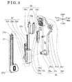
- the buttonhole switch mechanism 2 includes a buttonhole switching lever (i.e., serving as a lever member) 21, a buttonhole switching arm (i.e., serving as a lever member) 22, a switch lever (i.e., serving as a lever member) 23, a detection switch 24, and an attaching portion 25.
- a buttonhole switching lever i.e., serving as a lever member
- a buttonhole switching arm i.e., serving as a lever member
- a switch lever i.e., serving as a lever member
- an attaching portion 25 After integrally assembling the buttonhole switching lever 21, the buttonhole switching arm 22, the switch lever 23, the detection switch 24, and the attaching portion 25 as a unit, as illustrated in Fig. 1 , by fixing the unit onto the left-hand side of the upper arm portion 1 a of the machine frame 1 via a base plate 26 by means of the screw, the buttonhole switch mechanism 2 is attached to the machine frame 1.
- the buttonhole switching lever 21 is a bar shaped, or rod shaped member having a cross-section in rectangular shape and elongated in an upward-downward direction.
- the buttonhole switching lever 21 is provided with an engagement pawl 21a at an upper end and a knob portion (lower end portion) 21 b at a lower end.
- the buttonhole switching lever 21 is inserted from the downward to the upward into a lever retaining portion 22b of the buttonhole switching arm 22 so that the buttonhole switching lever 21 is retained to be slidable in an upward-downward direction relative to the buttonhole switching arm 22.
- the buttonhole switching arm 22 is formed with a first switch lever thrusting portion 22a, a second switch lever thrusting portion 22d, the lever retaining portion 22b, and a bearing hole 22c.
- the second switch lever thrusting portion 22d is provided at, or diverges from a middle, or a center portion of the buttonhole switching arm 22 in an upward-downward direction to protrude forward and upward.
- the lever retaining portion 22b is provided at a lower portion of the buttonhole switching arm 22.
- the bearing hole 22c is provided at a forward of the lever retaining portion 22b and penetrates through in a rightward-leftward direction.
- the first switch lever thrusting portion 22a includes a round portion protruding forward and protrudes higher than the second switch lever thrusting portion 22d.
- the second switch lever thrusting portion 22d includes a round portion protruding rearward and is positioned at a lower end level of the first switch lever thrusting portion 22a.
- the lever retaining portion 22b is formed in a sleeve or pipe shape which extends in an upward-downward direction and is formed to have a rectangular cross-section.
- the bearing hole 22c is positioned at a portion below the diverging portion of the first switch lever thrusting portion 22a and the second switch lever thrusting portion 22d.
- a rotation shaft 25a formed at the attaching portion 25 is positioned inside the bearing hole 22c, and an engagement pawl formed at a distal end of the rotation shaft 25a is engaged with a left-hand end of the bearing hole 22c to prevent the buttonhole switching arm 22 from falling off from the rotation shaft 25a.
- the buttonhole switching arm 22 is supported by the rotation shaft 25a formed at the attaching portion 25 to be rotatable in a front-rear direction in a state where the buttonhole switching lever 21 is retained at the lever retaining portion 22b.
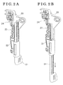
- the buttonhole switching lever 21 By a user's operation of the buttonhole switching lever 21, pinching the knob portion 21 b to draw the buttonhole switching lever 21 downward, the buttonhole switching lever 21 is switched from a housed state (normal sewing state) shown in Fig. 2A to a lowered position state shown in Fig. 2B . Then, the knob portion 21 b of the buttonhole switching lever 21 comes to contact with the buttonhole presser 7 to electrically conduct the detection switch 24 so that a control portion 8 (see Fig. 7 ) determines that the buttonhole switching lever 21 is at the lowered position and a state which allows the buttonhole sewing is established (see Fig. 6 ). At the lowered position state of the buttonhole switching lever 21 shown in Fig. 2B , by the engagement of the engagement pawl 21 a with the upper end of the lever retaining portion 22b, the buttonhole switching lever 21 is prevented from falling off from the lever retaining portion 22b.
- the switch lever 23 includes a switch action portion 23a at an upper end thereof, a point of application 23b at a lower end thereof, and a rotation center 23c at a lower portion relative to the center thereof.
- the switch action portion 23a includes a round portion protruding forward, positioned at a forward of the first switch lever thrusting portion 22a and at an approximately the same height with an end of the first switch lever thrusting portion 22a so as to be contactable with the first switch lever thrusting portion 22a.
- the point of application 23b is positioned between the second switch lever thrusting portion 22d and the lower end of the first switch lever thrusting portion 22a at the portion where the first switch lever thrusting portion 22a and the second switch lever thrusting portion 22d of the buttonhole switching arm 22 diverge, and the point of application 23b is contactable with the second switch lever thrusting portion 22d.
- the rotation center 23c penetrates in the right-left direction and a rotation shaft 25b formed at the attaching portion 25 is inserted to be positioned in the rotation center 23c.
- An engagement pawl formed at a distal end of the rotation shaft 25b is engaged with the rotation center 23c in the front-rear direction so as to prevent the switch lever 23 from falling off from the rotation shaft 25b.
- the detection switch 24 includes a first contact piece 241 and a second contact piece 242 each made of metal.
- Each of the first contact piece 241 and the second contact piece 242 includes a harness connection portion 24a at an upper end thereof, a bent portion 24b at a lower end thereof, a plane portion 24c which is formed in a rectangular strip shape elongated in an upward-downward direction and connects the harness connection portion 24a and the bent portion 24b, and a fitting portion 24d formed above the plane portion 24c.
- the first contact piece 241 and the second contact piece 242 have the same configuration and dimension.
- the harness connection portion 24a is formed with a through hole penetrating in an approximately front-rear direction and is connected to a harness for transmitting an input signal to the control portion 8.
- the bent portion 24b is bent in a substantially right angle relative to the plane portion 24c.
- the fitting portion 24d is bent in a substantially U-shape to protrude to the opposite direction relative to the bent portion 24b.
- the first contact piece 241 and the second contact piece 242 are arranged so that the bent portions 24b protrude to oppose to each other and are shifted in an upward-downward direction from each other and face one another in the front-rear direction.
- the detection switch 24 is fixed to the attaching portion 25 by snap-fitting the fitting portion 24d to a detection switch fixing portion 25d.
- the second contact piece 242 is shifted downward so that the bent portion 24b of the first contact piece 241 faces the plane portion 24c of the second contact piece 242 with a distance.
- the second contact piece 242 is positioned at the rearward relative to the first contact piece 241.
- the plane portion 24c of the second contact piece 242 is positioned at the forward of the switch action portion 23a of the switch lever 23.
- the bent portion 24b of the first contact piece 241 serves as a first contact point.
- a portion of the plane portion 24c of the second contact piece 242 which is positioned opposing to, or facing the bent portion 24b of the first contact piece 241 serves as a second contact point.
- the second switch lever thrusting portion 22d thrusts the point of application 23b of the switch lever 23 in a rearward direction (i.e., the counterclockwise direction).
- the first switch lever thrusting portion 22a thrusts the switch action portion 23a of the switch lever 23 in the forward direction (i.e., counterclockwise direction). Namely, irrespective of the rotation direction of the buttonhole switching arm 22, the switch lever 23 always operates in the counterclockwise direction.
- the switch action portion 23a thrusts, or pushes the plane portion 24c of the second contact piece 242, the plane portion 24c is elastically deformed, the second contact point displaces towards the bent portion 24b serving as the first contact point, and the detection switch 24 is electrically conducted when the plane portion 24c contacts the bent portion 24b.
- the first switch lever thrusting portion 22a rotates the switch lever 23
- the second switch lever thrusting portion 22d and other portions of the buttonhole switching arm 22 do not interfere with the switch lever 23.
- the second switch lever thrusting portion 22d rotates the switch lever 23
- the first switch lever thrusting portion 22a and other portions of the buttonhole switching arm 22 do not interfere with the switch lever 23.
- the integrated buttonhole switching lever 21, the buttonhole switching arm 22, and the switch lever 23 serve as a lever member.
- the attaching portion 25 is a plate-shaped member having surfaces extending in an upward-downward direction and front-rear direction and elongated in the upward-downward direction.
- the rotation shaft 25a for the buttonhole switching arm 22, the rotation shaft 25a protruding in the leftward, is formed at a lower portion of the surface of the attaching portion 25.
- the rotation shaft 25b for the switch lever 23, the rotation shaft 25b protruding in the leftward direction, is formed at a center portion of the attaching portion 25.
- a stopper hole 25c that is an elongated hole elongated in the front-rear direction and penetrated in the right-left direction is formed between the rotation shaft 25a and the rotation shaft 25b in the upward-downward direction.
- the detection switch fixing portion 25d for fixing the detection switch 24 is formed at a face of an upper front portion of the attaching portion 25.
- a screw stopper hole 25e which is an elongated hole elongated in a front-rear direction and penetrating in right-left direction is formed at an upper rear portion of the surfaces of the attaching portion 25.
- a pin 25f protruding in a rightward direction is provided at a backside (right-hand surface) of the attaching portion 25 at slightly lower position relative to the screw stopper hole 25e.
- the attaching portion 25 is fixed to the base plate 26 by means of a fixation screw (set screw) 11 that is positioned in the screw stopper hole 25e in a state where the pin 25f is positioned in a long hole of the base plate 26 (see Fig. 6 ).
- the buttonhole presser 7 includes a presser frame 72 that is a main body of the buttonhole presser 7, a button diameter measurement member 71 that is provided to be slidable in a front-rear direction relative to the presser frame 72, and a slide member 73 that is provided to be slidable on the presser frame 72.
- the slide member 73 is biased to contact the presser frame 72 by a tensile force of a spiral spring (power spring) provided within the presser frame 72.
- a spiral spring power spring
- the presser frame 72 includes a plane surface formed in a rectangular shape elongated in a front-rear direction.
- a lever operation arm 72a serving as a projection portion, that protrudes upward and leftward is formed at an intermediate portion of the presser frame 72 at leftwards in the front-rear direction.
- a button contact surface 72b that protrudes upward is formed at a front end of the presser frame 72.
- a stopper 72c that is configured to contact the slide member 73 is formed at a rear portion within the presser frame 72. The slide member 73 is biased to contact the stopper 72c by means of a biasing force (spring force) of a biasing member.
- the button diameter measurement member 71 includes a plane surface formed in a rectangular shape elongated in a front-rear direction. Long sides at right-hand and left-hand of the button diameter measurement member 71 are slidably supported by long sides at right-hand and left-hand of the presser frame 72 in a sandwiched manner.
- a lever operation arm 71 a serving as a projection portion, protruding upward and leftward is formed at a leftward-rear end of the button diameter measurement member 71.
- a button contact surface 71 b protruding upward is formed at a front end of the button diameter measurement member 71.
- the lever operation arm 71 a contacts the lever operation arm 72a and the button contact surface 71 b contacts the button contact surface 72b.
- a distance H between the lever operation arm 71 a of the button diameter measurement member 71 and the lever operation arm 72a of the presser frame 72 change in accordance with a diameter of the button B. Length (dimension) of the buttonhole when finishing sewing is determined by the distance H.
- Figs. 6A, 6B, 6C illustrate transitional states of the operation of the buttonhole switch mechanism 2 and the buttonhole presser 7 when performing the buttonhole sewing.
- Fig. 6A shows a state A where the buttonhole presser 7 is at a start position for the buttonhole sewing.
- Fig. 6B shows a state B where the buttonhole presser 7 is at a reverse position for the buttonhole sewing.
- Fig. 6C shows a state C where the buttonhole presser 7 is at a position where the buttonhole sewing is completed.
- the buttonhole switching lever 21 is at the housed state.
- the bent portion 24b of the first contact piece 241 of the detection switch 24 and the plane portion 24c of the second contact piece 242 are separated, and the detection switch 24 is not electrically conducted because the first contact point and the second contact point are not in contact (disconnected).
- the slide member 73 of the buttonhole presser 7 comes to contact the stopper 72c to establish a state where the presser frame 72 is moved to be positioned at a foremost position.
- the buttonhole switching arm 22 rotates in the clockwise direction about the rotation shaft 25a and the second switch lever thrusting portion 22d thrusts the point of application 23b of the switch lever 23 in a rearward direction (i.e., direction X2 in Fig. 6 ).
- the switch lever 23 rotates in the counterclockwise direction about the rotation center 23c, the plane portion 24c of the second contact piece 242 is thrust, or pushed by the switch action portion 23a in a forward direction (i.e., direction X1 in Fig.
- the buttonhole is sewn automatically in an order shown in Fig. 8 .
- the control portion 8 controls a sewing machine actuation motor 9a (see Fig. 7 ) to perform straight stitching while moving the cloth rearward (i.e., direction X2 in Fig. 6 ) together with the buttonhole presser 7 by means of a feed mechanism with the feed dog 6 of the sewing machine frame M.
- the buttonhole switching arm 22 rotates in the counterclockwise direction about the rotation shaft 25a so that the first switch lever thrusting portion 22a thrusts, or pushes the switch action portion 23a of the switch lever 23 forward (i.e., direction X1 in Fig. 6 ).
- the switch lever 23 rotates in the counterclockwise direction about the rotation center 23c and the plane portion 24c of the second contact piece 242 is thrust, or pushed forward (i.e., direction X1 in Fig.
- the control portion 8 reverses the feeding direction of the cloth (fabric) to the forward by moving a feed mechanism stepping motor 9b.
- the control portion 8 reverses the feeding direction of the cloth, or fabric to the rearward (i.e., direction X2 in Fig. 6 ) by moving the feed mechanism stepping motor 9b.
- the control portion 8 performs a zigzag sewing by moving the sewing needle 4 in the right-left direction alternatively by a swing width mechanism stepping motor 9c. Accordingly, in response to the input number of times of the input signal of the detection switch 24 (buttonhole sensor) shown in Fig. 7 , the control portion 8 controls the sewing machine actuation motor (i.e., serving as an output portion) 9a, the feed mechanism stepping motor (i.e., serving as an output portion) 9b, and the swing width mechanism stepping motor (i.e., serving as an output portion) 9c to automatically perform the buttonhole sewing in the order indicated with 101 to 108 in Fig. 8 .
- the sewing machine actuation motor i.e., serving as an output portion
- the feed mechanism stepping motor i.e., serving as an output portion
- the swing width mechanism stepping motor i.e., serving as an output portion
- the correspondence of the input number of times of the input signal of the buttonhole sensor and the procedures 101 to 108 is as shown in Fig. 9 .
- the counter number is reset when exceeding eight (8) or when the start/stop switch 10 of the sewing machine frame M is pressed. As long as the control portion 8 enables to judge that an input signal is transmitted from the detection switch 24 (buttonhole sensor), any form of input signal is applicable.
- the knob portion 21 b of the buttonhole switching lever 21 is disengaged from (non-contact) the lever operation arm 71 a or the lever operation arm 72a of the buttonhole presser 7 in positional states between states shown in Fig. 6A and Fig. 6B , and between states shown in Fig. 6B and Fig. 6C .
- a clearance, or gap is made between the contact portion (bent portion 24b) of the first contact piece 241 and the plane portion 24c of the second contact piece 242.
- first switch lever thrusting portion 22a of the buttonhole switching arm 22 and the switch action portion 23a of the switch lever 23 are in contact with each other and the second switch lever thrusting portion 22d of the buttonhole switching arm 22 and the point of application 23b of the switch lever 23 are in contact with each other.
- whisker-shaped stitching pattern corresponding to length D1 may be generated, which impairs the appearance of the finished buttonhole.
- the sewing trace that impairs the appearance is generated provided that the user makes the knob portion 21 b of the buttonhole switching lever 21 contact the lever operation arm 72a of the buttonhole presser 7 excessively to excessively thrust the detection switch 24 in the state A shown in Fig. 6 whereas the thrust amount of the detection switch 24 when the knob portion 21 b automatically contacts the lever operation arm 72a is the minimum necessary amount in the state C in Fig. 6 .
- the state C shown in Fig. 6 as indicated with 103 and 106 in Fig.
- the feeding direction of the cloth (fabric) is reversed at a timing before returning to the state A at the start position.
- the sewing trace that impairs the appearance is unlikely generated in a case where the thrust amount of the detection switch 24 at the state A in Fig. 6 is the minimum necessary amount likewise the thrust amount of the detection switch 24 at the state C in Fig. 6 .
- the position for electrically conducting the detection switch may be adjusted so that the excessive thrust amount of the detection switch 24 in the state A in Fig. 6A is assumed to be equal to the minimum requirements of the thrust amount of the detection switch 24 in the state C in Fig. 6C .
- an adjusting mechanism for performing the foregoing adjustment is disclosed in JP2011-283091A .
- the buttonhole switch mechanism according to this embodiment may include a similar adjusting mechanism.
- the fitting portion 24d of the detection switch 24 is strengthen (rigidly formed) by being bent in a U-shape and a base portion of the plane portion 24c extended from the bent portion 24b (i.e., the portion fixed to the detection switch fixing portion 25d) serves as a fulcrum for the elastic deformation and thus the buttonhole switch mechanism 2 is formed in a relatively small dimension (equal to or less than 20 millimeter in the total length).
- the detection switch 24 of the embodiment because the contact pieces (241, 242) formed in the same configuration and dimension are used and are positioned in a manner that the bent portions 24b are opposed to one another where the contact pieces are displaced from one another in an upward-downward direction, productivity in the mass production is enhanced.
- a single contact switch with lower price may be readily applicable.
- a sewing machine with lower price can be provided to end users.
- the buttonhole switch mechanism of the disclosure is not limited to the above-described embodiment.
- the lever members (21 to 23) are not limited to the construction to thrust, or push the second contact piece 242 of the detection switch 24 in one direction.
- the first contact piece 241 and the second contact piece 242 may be pushed towards the opposing contact pieces one another.
Landscapes
- Engineering & Computer Science (AREA)
- Textile Engineering (AREA)
- Sewing Machines And Sewing (AREA)
Abstract
Description
- This disclosure generally relates to a buttonhole sewing machine that enables to automatically sew buttonholes.
- According to a sewing machine that is configured to sew buttonholes, it is necessary to change buttonhole sewing lengths in accordance with diameters of buttons. For example, computerized sewing machines disclosed in
JPH08-141235A JP2008-12052A - The computerized sewing machine disclosed in
Patent reference 1 is provided with a buttonhole sensor for detecting the diameter of the button at a housing of a machine main body. The buttonhole sensor is structured with a detection lever, a button case and a variable resistor (slide volume). After setting the button in the button case, by providing the button between an inner wall of the button case and the detection lever by moving the detection lever, a resistance value of the variable resistor changes in response to a moving amount of the detection lever, and the diameter of the button corresponding to the resistance value can be detected. At a CPU of the sewing machine, sewing data of the buttonhole is created on the basis of the feed amount of the cloth that a user set and on the basis of the detected diameter of the button, and the buttonhole is automatically sewn on the basis of the sewing data. - The computerized sewing machine disclosed in
Patent reference 2 includes the built-in variable resistor at a buttonhole presser attached at a bottom end of a presser bar of the sewing machine. The buttonhole presser includes a presser member fixed to the presser bar and a presser frame that slides in a front-rear direction relative to the presser member. A relative displacement of the presser member and the presser frame is detectable by the variable resistor. According to the sewing machine disclosed inPatent reference 2, the buttonholes are automatically sewn while detecting the diameter of the button mounted to the buttonhole presser and constantly detecting the position of the buttonhole presser on the basis of the changes in the resistance value of the variable resistor. - According to the sewing machine disclosed in
Patent reference 1, the variable resistor is applied as the detection mechanism for detecting the diameter of the button while the variable resistor is applied as the detection mechanism for detecting the diameter of the button and the position of the buttonhole presser according to the sewing machine disclosed inPatent reference 2. Thus, the sewing machines disclosed inPatent references - Further, according to the sewing machine disclosed in
Patent reference 2, because the variable resistor is built in the buttonhole presser, it is necessary to connect a harness extending from the buttonhole presser to a connection portion of the sewing machine main body. Thus, a user has to be careful so as not to hook the cloth onto the harness during the sewing process and when setting the cloth, the fabric work piece, to the sewing machine. - According to a sewing machine disclosed in Japanese Patent Application No.
2011-283091 Patent reference 3 allows to automatically sew buttonholes with lower costs than by the constructions disclosed inPatent references Patent reference 3, it is necessary to use two single contact switches which are relatively lower price or one double contact switch which is relatively higher price. -
JP2003-141960A Patent reference 4 realizes a mounting operation of a stable contact point with high reliability readily and in a simple manner. However, because the switch base needs the plural bosses in order to prevent the deformation other than the plane portion and to prevent the contact pieces from falling down when deformed, the switch device ofPatent reference 4 is not suitable for smaller contact pieces having length equal to or shorter than 20 millimeters. That is, the switch device ofPatent reference 4 is not suitable for a device in which parts with various functions are disposed in small space, for example, a sewing machine. Further, a structure for realizing a fulcrum for the elastic deformation by retaining the plane portion is manufactured by insert molding, which increases manufacturing costs. - A need thus exists for a buttonhole sewing machine which automatically sews buttonholes and is lower price.
- In light of the foregoing, the disclosure provides a buttonhole sewing machine, which includes a buttonhole presser including a presser frame mounted to a lower end of a presser bar and being movable in a front-rear direction relative to the presser bar and two projection portions positioned keeping a distance from one another in the front-rear direction in accordance with a diameter of a button, the projection portions moving integrally with the presser frame, a feed dog provided below the buttonhole presser and moving a fabric work piece in a front-rear direction with a predetermined feed pitch in cooperation with the presser frame, a sewing needle moving in an upward and downward direction to form stitches on the fabric work piece and configured to move in a right-left direction, a buttonhole switch mechanism including a detection switch provided at an arm portion and changing an open and closed states when the presser frame is positioned at a foremost position and at a rearmost position, the buttonhole switch mechanism including a lever member having a lower end portion positioned between said two projection portions of the buttonhole presser and rotatably supported for moving the lower end portion in a front-rear direction, and a control portion controlling a motion of the sewing needle and the feed dog on the basis of changes in the open and closed states of the detection switch. The detection switch includes first and second contact points that are selectively connected to each other. The lever member changes the open and closed states of the detection switch when the lower end portion rotates by being thrust by the projection portions, respectively.
- According to another aspect of the disclosure, the detection switch includes a first contact piece including the first contact point and a second contact piece including the second contact point and made from a leaf spring, the second contact piece is fixed at a first end and facing the first contact point with a distance at a second end and the second contact piece is configured to displace towards the first contact point in response to a rotation of the lever member.
- According to still another aspect of the disclosure, the first contact piece includes a plane portion formed in a rectangular strip shape and a bent portion protruding from an end of the plane portion to bend to be opposing to the second contact piece, and the second contact piece is formed in the same configuration with the first contact piece and is fixed in a state being shifted in an upward-downward direction relative to the first contact piece.
- According to further aspect of the disclosure, the lever member includes a switch lever including a switch action portion, a point of application and a rotation center provided between the switch action portion and the point of application, the switch action portion changes the open and closed states of the detection switch when the switch lever rotates in a first direction. The lever member includes a buttonhole switching arm including a first switch lever thrusting portion thrusting the switch action portion to rotate the switch lever in the first direction by rotating in the first direction and a second switch lever thrusting portion thrusting the point of application to rotate the switch lever in the first direction by rotating in a second direction. One of the first switch lever thrusting portion and the second switch lever thrusting portion does not interfere with the switch lever when the other one of the first switch lever thrusting portion and the second switch lever thrusting portion thrusts the switch lever in the first direction. The first switch lever thrusting portion and the second switch lever thrusting portion are in contact with the switch lever when the lower end portion is not pushed by the projection portions.
- According to the disclosure, the buttonhole switch mechanism with lower price can be attained.
- The foregoing and additional features and characteristics of this disclosure will become more apparent from the following detailed description considered with the reference to the accompanying drawings, wherein:
-
Fig. 1 is a perspective view of a buttonhole sewing machine in a state where a housing is removed according to an embodiment disclosed here; -
Fig. 2A is a perspective view of a buttonhole switch mechanism for the buttonhole sewing machine in a state where a buttonhole switching lever is housed according to the embodiment disclosed here; -
Fig. 2B is a perspective view of the buttonhole switch mechanism for the buttonhole sewing machine in a state where the buttonhole switching lever is at a lowered state according to the embodiment disclosed here; -
Fig. 3 is an exploded perspective view of the buttonhole switch mechanism for the buttonhole sewing machine according to the embodiment disclosed here; -
Fig. 4 is a perspective view of a buttonhole presser combined with the buttonhole switch mechanism for the buttonhole sewing machine according to the embodiment disclosed here; -
Fig. 5 is an explanatory exploded perspective view of a main portion of the buttonhole switch mechanism for the buttonhole sewing machine showing a state where a detection switch is not conducted according to the embodiment disclosed here; -
Fig. 6A is an explanatory view showing an operation of the buttonhole switch mechanism for the buttonhole sewing machine in a state where the buttonhole presser is at a start position for sewing a buttonhole according to the embodiment disclosed here; -
Fig. 6B is an explanatory view showing the operation of the buttonhole switch mechanism for the buttonhole sewing machine in a state where the buttonhole presser is at a reverse position for sewing the buttonhole according to the embodiment disclosed here; -
Fig. 6C is an explanatory view showing the operation of the buttonhole switch mechanism for the buttonhole sewing machine in a state where the buttonhole presser is at a position where the buttonhole sewing is completed according to the embodiment disclosed here; -
Fig. 7 is a block diagram for a control portion of the buttonhole sewing machine provided with the buttonhole switch mechanism according to the embodiment disclosed here; -
Fig. 8 is an explanatory view for explaining procedures of buttonhole sewing by the buttonhole sewing machine provided with the buttonhole switch mechanism according to the embodiment disclosed here; and -
Fig. 9 is a table showing relationships between count numbers by a detection switch and the procedures of the buttonhole sewing by the buttonhole switch mechanism for the buttonhole sewing machine according to the embodiment disclosed here. - One embodiment of a buttonhole sewing machine will be explained with reference to
Figs. 1 to 9 as follows. Up (upper, top), down (lower, bottom), right (rightward), left (leftward), front (forward), rear (rearward) in the descriptions refer to up (upper, top), down (lower, bottom), right (rightward), left (leftward), front (forward), rear (rearward) inFig. 1 and indicate up (upper, top), down (lower, bottom), right (rightward), left (leftward), front (forward), rear (rearward) for a user when the user uses the sewing machine. - A main body of the sewing machine includes a housing serving as a contour of the sewing machine and a sewing machine frame M serving as a main element that is covered with the housing. As illustrated in
Fig. 1 , the sewing machine frame M is structured with a machine frame 1 (immovable portion) and various component parts for the sewing machine mounted to themachine frame 1. Themachine frame 1 includes an upper arm portion (serving as an arm portion) 1a, a bed portion (work supporting arm) 1b provided at a lower portion, and avertical arm portion 1c connecting theupper arm portion 1 a and thebed portion 1 b at right-hand bottom end of theupper arm portion 1 a and right-hand top end of thebed portion 1 b. Abuttonhole switch mechanism 2, apresser bar 3, and asewing needle 4 are provided at a left end of theupper arm portion 1 a of themachine frame 1. Thepresser bar 3 is movable in an upward-downward direction in accordance with a thickness of a fabric which serves as a work piece. Thesewing needle 4 is configured to form stitches in response to an upward-downward motion thereof and to move in rightward-leftward directions. Athroat plate 5 and afeed dog 6 which protrudes and retracts relative to an upper surface of thethroat plate 5 for feeding a fabric work piece are disposed at the leftward portion of thebed portion 1 b of themachine frame 1. Abuttonhole presser 7 is attached to apresser holder 3a that is fixed to a bottom end of thepresser bar 3 by means of a screw. - As illustrated in
Figs. 2A, 2B , and3 , thebuttonhole switch mechanism 2 includes a buttonhole switching lever (i.e., serving as a lever member) 21, a buttonhole switching arm (i.e., serving as a lever member) 22, a switch lever (i.e., serving as a lever member) 23, adetection switch 24, and an attachingportion 25. After integrally assembling thebuttonhole switching lever 21, thebuttonhole switching arm 22, theswitch lever 23, thedetection switch 24, and the attachingportion 25 as a unit, as illustrated inFig. 1 , by fixing the unit onto the left-hand side of theupper arm portion 1 a of themachine frame 1 via abase plate 26 by means of the screw, thebuttonhole switch mechanism 2 is attached to themachine frame 1. - The
buttonhole switching lever 21 is a bar shaped, or rod shaped member having a cross-section in rectangular shape and elongated in an upward-downward direction. Thebuttonhole switching lever 21 is provided with anengagement pawl 21a at an upper end and a knob portion (lower end portion) 21 b at a lower end. Thebuttonhole switching lever 21 is inserted from the downward to the upward into alever retaining portion 22b of thebuttonhole switching arm 22 so that thebuttonhole switching lever 21 is retained to be slidable in an upward-downward direction relative to thebuttonhole switching arm 22. - The
buttonhole switching arm 22 is formed with a first switchlever thrusting portion 22a, a second switchlever thrusting portion 22d, thelever retaining portion 22b, and abearing hole 22c. The second switchlever thrusting portion 22d is provided at, or diverges from a middle, or a center portion of thebuttonhole switching arm 22 in an upward-downward direction to protrude forward and upward. Thelever retaining portion 22b is provided at a lower portion of thebuttonhole switching arm 22. Thebearing hole 22c is provided at a forward of thelever retaining portion 22b and penetrates through in a rightward-leftward direction. The first switchlever thrusting portion 22a includes a round portion protruding forward and protrudes higher than the second switchlever thrusting portion 22d. The second switchlever thrusting portion 22d includes a round portion protruding rearward and is positioned at a lower end level of the first switchlever thrusting portion 22a. Thelever retaining portion 22b is formed in a sleeve or pipe shape which extends in an upward-downward direction and is formed to have a rectangular cross-section. Thebearing hole 22c is positioned at a portion below the diverging portion of the first switchlever thrusting portion 22a and the second switchlever thrusting portion 22d. Arotation shaft 25a formed at the attachingportion 25 is positioned inside thebearing hole 22c, and an engagement pawl formed at a distal end of therotation shaft 25a is engaged with a left-hand end of thebearing hole 22c to prevent thebuttonhole switching arm 22 from falling off from therotation shaft 25a. Thebuttonhole switching arm 22 is supported by therotation shaft 25a formed at the attachingportion 25 to be rotatable in a front-rear direction in a state where thebuttonhole switching lever 21 is retained at thelever retaining portion 22b. - By a user's operation of the
buttonhole switching lever 21, pinching theknob portion 21 b to draw thebuttonhole switching lever 21 downward, thebuttonhole switching lever 21 is switched from a housed state (normal sewing state) shown inFig. 2A to a lowered position state shown inFig. 2B . Then, theknob portion 21 b of thebuttonhole switching lever 21 comes to contact with thebuttonhole presser 7 to electrically conduct thedetection switch 24 so that a control portion 8 (seeFig. 7 ) determines that thebuttonhole switching lever 21 is at the lowered position and a state which allows the buttonhole sewing is established (seeFig. 6 ). At the lowered position state of thebuttonhole switching lever 21 shown inFig. 2B , by the engagement of theengagement pawl 21 a with the upper end of thelever retaining portion 22b, thebuttonhole switching lever 21 is prevented from falling off from thelever retaining portion 22b. - The
switch lever 23 includes aswitch action portion 23a at an upper end thereof, a point ofapplication 23b at a lower end thereof, and arotation center 23c at a lower portion relative to the center thereof. Theswitch action portion 23a includes a round portion protruding forward, positioned at a forward of the first switchlever thrusting portion 22a and at an approximately the same height with an end of the first switchlever thrusting portion 22a so as to be contactable with the first switchlever thrusting portion 22a. The point ofapplication 23b is positioned between the second switchlever thrusting portion 22d and the lower end of the first switchlever thrusting portion 22a at the portion where the first switchlever thrusting portion 22a and the second switchlever thrusting portion 22d of thebuttonhole switching arm 22 diverge, and the point ofapplication 23b is contactable with the second switchlever thrusting portion 22d. Therotation center 23c penetrates in the right-left direction and arotation shaft 25b formed at the attachingportion 25 is inserted to be positioned in therotation center 23c. An engagement pawl formed at a distal end of therotation shaft 25b is engaged with therotation center 23c in the front-rear direction so as to prevent theswitch lever 23 from falling off from therotation shaft 25b. - The
detection switch 24 includes afirst contact piece 241 and asecond contact piece 242 each made of metal. Each of thefirst contact piece 241 and thesecond contact piece 242 includes aharness connection portion 24a at an upper end thereof, abent portion 24b at a lower end thereof, aplane portion 24c which is formed in a rectangular strip shape elongated in an upward-downward direction and connects theharness connection portion 24a and thebent portion 24b, and afitting portion 24d formed above theplane portion 24c. Thefirst contact piece 241 and thesecond contact piece 242 have the same configuration and dimension. Theharness connection portion 24a is formed with a through hole penetrating in an approximately front-rear direction and is connected to a harness for transmitting an input signal to thecontrol portion 8. Thebent portion 24b is bent in a substantially right angle relative to theplane portion 24c. Thefitting portion 24d is bent in a substantially U-shape to protrude to the opposite direction relative to thebent portion 24b. In thedetection switch 24, thefirst contact piece 241 and thesecond contact piece 242 are arranged so that thebent portions 24b protrude to oppose to each other and are shifted in an upward-downward direction from each other and face one another in the front-rear direction. Thedetection switch 24 is fixed to the attachingportion 25 by snap-fitting thefitting portion 24d to a detectionswitch fixing portion 25d. Thesecond contact piece 242 is shifted downward so that thebent portion 24b of thefirst contact piece 241 faces theplane portion 24c of thesecond contact piece 242 with a distance. Thesecond contact piece 242 is positioned at the rearward relative to thefirst contact piece 241. Theplane portion 24c of thesecond contact piece 242 is positioned at the forward of theswitch action portion 23a of theswitch lever 23. Thebent portion 24b of thefirst contact piece 241 serves as a first contact point. A portion of theplane portion 24c of thesecond contact piece 242 which is positioned opposing to, or facing thebent portion 24b of thefirst contact piece 241 serves as a second contact point. - When the
buttonhole switching arm 22 rotates in the clockwise direction, the second switchlever thrusting portion 22d thrusts the point ofapplication 23b of theswitch lever 23 in a rearward direction (i.e., the counterclockwise direction). When thebuttonhole switching arm 22 rotates in the counterclockwise direction, the first switchlever thrusting portion 22a thrusts theswitch action portion 23a of theswitch lever 23 in the forward direction (i.e., counterclockwise direction). Namely, irrespective of the rotation direction of thebuttonhole switching arm 22, theswitch lever 23 always operates in the counterclockwise direction. Thus, theswitch action portion 23a thrusts, or pushes theplane portion 24c of thesecond contact piece 242, theplane portion 24c is elastically deformed, the second contact point displaces towards thebent portion 24b serving as the first contact point, and thedetection switch 24 is electrically conducted when theplane portion 24c contacts thebent portion 24b. When the first switchlever thrusting portion 22a rotates theswitch lever 23, the second switchlever thrusting portion 22d and other portions of thebuttonhole switching arm 22 do not interfere with theswitch lever 23. When the second switchlever thrusting portion 22d rotates theswitch lever 23, the first switchlever thrusting portion 22a and other portions of thebuttonhole switching arm 22 do not interfere with theswitch lever 23. The integratedbuttonhole switching lever 21, thebuttonhole switching arm 22, and theswitch lever 23 serve as a lever member. - The attaching
portion 25 is a plate-shaped member having surfaces extending in an upward-downward direction and front-rear direction and elongated in the upward-downward direction. Therotation shaft 25a for thebuttonhole switching arm 22, therotation shaft 25a protruding in the leftward, is formed at a lower portion of the surface of the attachingportion 25. Therotation shaft 25b for theswitch lever 23, therotation shaft 25b protruding in the leftward direction, is formed at a center portion of the attachingportion 25. Astopper hole 25c that is an elongated hole elongated in the front-rear direction and penetrated in the right-left direction is formed between therotation shaft 25a and therotation shaft 25b in the upward-downward direction. By the insertion of a pin provided at a reverse side (right-hand surface) of thebuttonhole switching arm 22 into thestopper hole 25c, a rotational range of thebuttonhole switching arm 22 is restricted. - The detection
switch fixing portion 25d for fixing thedetection switch 24 is formed at a face of an upper front portion of the attachingportion 25. Ascrew stopper hole 25e which is an elongated hole elongated in a front-rear direction and penetrating in right-left direction is formed at an upper rear portion of the surfaces of the attachingportion 25. Apin 25f protruding in a rightward direction is provided at a backside (right-hand surface) of the attachingportion 25 at slightly lower position relative to thescrew stopper hole 25e. The attachingportion 25 is fixed to thebase plate 26 by means of a fixation screw (set screw) 11 that is positioned in thescrew stopper hole 25e in a state where thepin 25f is positioned in a long hole of the base plate 26 (seeFig. 6 ). - As illustrated in
Fig. 4 , thebuttonhole presser 7 includes apresser frame 72 that is a main body of thebuttonhole presser 7, a buttondiameter measurement member 71 that is provided to be slidable in a front-rear direction relative to thepresser frame 72, and aslide member 73 that is provided to be slidable on thepresser frame 72. Theslide member 73 is biased to contact thepresser frame 72 by a tensile force of a spiral spring (power spring) provided within thepresser frame 72. By the attachment of theslide member 73 to thepresser holder 3a provided at the lower end of thepresser bar 3, thepresser frame 72 is movable in the front-rear direction relative to thepresser bar 3. - The
presser frame 72 includes a plane surface formed in a rectangular shape elongated in a front-rear direction. Alever operation arm 72a, serving as a projection portion, that protrudes upward and leftward is formed at an intermediate portion of thepresser frame 72 at leftwards in the front-rear direction. Abutton contact surface 72b that protrudes upward is formed at a front end of thepresser frame 72. Astopper 72c that is configured to contact theslide member 73 is formed at a rear portion within thepresser frame 72. Theslide member 73 is biased to contact thestopper 72c by means of a biasing force (spring force) of a biasing member. - The button
diameter measurement member 71 includes a plane surface formed in a rectangular shape elongated in a front-rear direction. Long sides at right-hand and left-hand of the buttondiameter measurement member 71 are slidably supported by long sides at right-hand and left-hand of thepresser frame 72 in a sandwiched manner. Alever operation arm 71 a, serving as a projection portion, protruding upward and leftward is formed at a leftward-rear end of the buttondiameter measurement member 71. Abutton contact surface 71 b protruding upward is formed at a front end of the buttondiameter measurement member 71. When the buttondiameter measurement member 71 is at a rearmost slidable position relative to thepresser frame 72, thelever operation arm 71 a contacts thelever operation arm 72a and thebutton contact surface 71 b contacts thebutton contact surface 72b. As illustrated inFigs. 1 ,4 and6 , when a button B is sandwiched between thebutton contact surface 71 b of the buttondiameter measurement member 71 and thebutton contact surface 72b of thepresser frame 72, a distance H between thelever operation arm 71 a of the buttondiameter measurement member 71 and thelever operation arm 72a of thepresser frame 72 change in accordance with a diameter of the button B. Length (dimension) of the buttonhole when finishing sewing is determined by the distance H. - The buttonhole sewing by the computerized sewing machine including the
buttonhole switch mechanism 2 and thebuttonhole presser 7 will be explained with reference toFigs. 5 to 9 .Figs. 6A, 6B, 6C illustrate transitional states of the operation of thebuttonhole switch mechanism 2 and thebuttonhole presser 7 when performing the buttonhole sewing.Fig. 6A shows a state A where thebuttonhole presser 7 is at a start position for the buttonhole sewing.Fig. 6B shows a state B where thebuttonhole presser 7 is at a reverse position for the buttonhole sewing.Fig. 6C shows a state C where thebuttonhole presser 7 is at a position where the buttonhole sewing is completed. - In a normal sewing state, as illustrated in
Figs. 1 and2A , thebuttonhole switching lever 21 is at the housed state. In those circumstances, as illustrated inFig. 5 , thebent portion 24b of thefirst contact piece 241 of thedetection switch 24 and theplane portion 24c of thesecond contact piece 242 are separated, and thedetection switch 24 is not electrically conducted because the first contact point and the second contact point are not in contact (disconnected). In this case, as a preparatory operation for performing the buttonhole sewing by the user, as illustrated inFig. 4 , theslide member 73 of thebuttonhole presser 7 comes to contact thestopper 72c to establish a state where thepresser frame 72 is moved to be positioned at a foremost position. - As illustrated in
Fig. 6A , upon drawing theknob portion 21 b provided at the lower end of thebuttonhole switching lever 21 downward to contact thelever operation arm 72a of thebuttonhole presser 7, thebuttonhole switching arm 22 rotates in the clockwise direction about therotation shaft 25a and the second switchlever thrusting portion 22d thrusts the point ofapplication 23b of theswitch lever 23 in a rearward direction (i.e., direction X2 inFig. 6 ). Theswitch lever 23 rotates in the counterclockwise direction about therotation center 23c, theplane portion 24c of thesecond contact piece 242 is thrust, or pushed by theswitch action portion 23a in a forward direction (i.e., direction X1 inFig. 6 ) to be elastically deformed thus contacting thebent portion 24b of thefirst contact piece 241 to electrically conduct. This electric conduction corresponds to an input signal of the detection switch 24 (buttonhole sensor) shown inFig. 7 . In a case where the user selects a buttonhole sewing mode, by controlling for allowing the activation of the sewing machine by a foot controller connected to the sewing machine frame M or start/stop switch (i.e., serving as an input portion) 10 only when the input signal of the detection switch 24 (buttonhole sensor) is conducted, the activation of the sewing machine while the user forget drawing, or moving thebuttonhole switching lever 21 downward is prevented. - When the user activates the sewing machine by the operation of the start/
stop switch 10 of the sewing machine frame M or by the operation of the foot controller connected to the sewing machine frame M, the buttonhole is sewn automatically in an order shown inFig. 8 . When the sewing machine is activated in a state indicated with 101 inFig. 8 and a state shown inFig. 6A (defined as state A), thecontrol portion 8 controls a sewingmachine actuation motor 9a (seeFig. 7 ) to perform straight stitching while moving the cloth rearward (i.e., direction X2 inFig. 6 ) together with thebuttonhole presser 7 by means of a feed mechanism with thefeed dog 6 of the sewing machine frame M. Then, when theknob portion 21 b of thebuttonhole switching lever 21 comes in contact with thelever operation arm 71 a of thebuttonhole presser 7, thebuttonhole switching arm 22 rotates in the counterclockwise direction about therotation shaft 25a so that the first switchlever thrusting portion 22a thrusts, or pushes theswitch action portion 23a of theswitch lever 23 forward (i.e., direction X1 inFig. 6 ). Theswitch lever 23 rotates in the counterclockwise direction about therotation center 23c and theplane portion 24c of thesecond contact piece 242 is thrust, or pushed forward (i.e., direction X1 inFig. 6 ) by theswitch action portion 23a and is elastically deformed so as to contact thebent portion 24b of thefirst contact piece 241, thus to electrically conduct thedetection switch 24. This electric conduction corresponds to an input signal of the detection switch 24 (buttonhole sensor) shown inFig. 7 . Thecontrol portion 8 reverses the feeding direction of the cloth (fabric) to the forward by moving a feedmechanism stepping motor 9b. - In a state indicated with 103 in
Fig. 8 corresponding to a state shown inFig. 6C (defined as state C), similarly to the state A inFig. 6A , theplane portion 24c of thesecond contact piece 242 is thrust, or pushed forward (i.e., direction X1 inFig. 6 ) to be elastically deformed and to come to contact thebent portion 24b of thefirst contact piece 241 to electrically conduct thedetection switch 24 so that the input signal of the detection switch 24 (buttonhole sensor) shown inFig. 7 is transmitted to thecontrol portion 8. Thecontrol portion 8 reverses the feeding direction of the cloth, or fabric to the rearward (i.e., direction X2 inFig. 6 ) by moving the feedmechanism stepping motor 9b. Then, in a state indicated with 104 shown inFig. 8 , thecontrol portion 8 performs a zigzag sewing by moving thesewing needle 4 in the right-left direction alternatively by a swing widthmechanism stepping motor 9c. Accordingly, in response to the input number of times of the input signal of the detection switch 24 (buttonhole sensor) shown inFig. 7 , thecontrol portion 8 controls the sewing machine actuation motor (i.e., serving as an output portion) 9a, the feed mechanism stepping motor (i.e., serving as an output portion) 9b, and the swing width mechanism stepping motor (i.e., serving as an output portion) 9c to automatically perform the buttonhole sewing in the order indicated with 101 to 108 inFig. 8 . The correspondence of the input number of times of the input signal of the buttonhole sensor and theprocedures 101 to 108 is as shown inFig. 9 . The counter number is reset when exceeding eight (8) or when the start/stop switch 10 of the sewing machine frame M is pressed. As long as thecontrol portion 8 enables to judge that an input signal is transmitted from the detection switch 24 (buttonhole sensor), any form of input signal is applicable. - According to the construction of the
buttonhole switch mechanism 2 and thebuttonhole presser 7, theknob portion 21 b of thebuttonhole switching lever 21 is disengaged from (non-contact) thelever operation arm 71 a or thelever operation arm 72a of thebuttonhole presser 7 in positional states between states shown inFig. 6A and Fig. 6B , and between states shown inFig. 6B and Fig. 6C . As illustrated inFig. 5 , by the elastic force of theplane portion 24c of thesecond contact piece 242, a clearance, or gap is made between the contact portion (bent portion 24b) of thefirst contact piece 241 and theplane portion 24c of thesecond contact piece 242. In those circumstances, the first switchlever thrusting portion 22a of thebuttonhole switching arm 22 and theswitch action portion 23a of theswitch lever 23 are in contact with each other and the second switchlever thrusting portion 22d of thebuttonhole switching arm 22 and the point ofapplication 23b of theswitch lever 23 are in contact with each other. - At the completion of the buttonhole sewing, at the sewing end indicated with 108 in
Fig. 8 , whisker-shaped stitching pattern (sewing trace) corresponding to length D1 may be generated, which impairs the appearance of the finished buttonhole. The sewing trace that impairs the appearance is generated provided that the user makes theknob portion 21 b of thebuttonhole switching lever 21 contact thelever operation arm 72a of thebuttonhole presser 7 excessively to excessively thrust thedetection switch 24 in the state A shown inFig. 6 whereas the thrust amount of thedetection switch 24 when theknob portion 21 b automatically contacts thelever operation arm 72a is the minimum necessary amount in the state C inFig. 6 . In consequence, in the state C shown inFig. 6 , as indicated with 103 and 106 inFig. 8 , the feeding direction of the cloth (fabric) is reversed at a timing before returning to the state A at the start position. In other words, the sewing trace that impairs the appearance is unlikely generated in a case where the thrust amount of thedetection switch 24 at the state A inFig. 6 is the minimum necessary amount likewise the thrust amount of thedetection switch 24 at the state C inFig. 6 . - In order to solve the above described problem, the position for electrically conducting the detection switch may be adjusted so that the excessive thrust amount of the
detection switch 24 in the state A inFig. 6A is assumed to be equal to the minimum requirements of the thrust amount of thedetection switch 24 in the state C inFig. 6C . For example, an adjusting mechanism for performing the foregoing adjustment is disclosed inJP2011-283091A - According to the
buttonhole switch mechanism 2 of the embodiment, thefitting portion 24d of thedetection switch 24 is strengthen (rigidly formed) by being bent in a U-shape and a base portion of theplane portion 24c extended from thebent portion 24b (i.e., the portion fixed to the detectionswitch fixing portion 25d) serves as a fulcrum for the elastic deformation and thus thebuttonhole switch mechanism 2 is formed in a relatively small dimension (equal to or less than 20 millimeter in the total length). Further, according to thedetection switch 24 of the embodiment, because the contact pieces (241, 242) formed in the same configuration and dimension are used and are positioned in a manner that thebent portions 24b are opposed to one another where the contact pieces are displaced from one another in an upward-downward direction, productivity in the mass production is enhanced. Instead of the switch described above, a single contact switch with lower price may be readily applicable. Thus, according to thebuttonhole switch mechanism 2 of the embodiment, a sewing machine with lower price can be provided to end users. - The buttonhole switch mechanism of the disclosure is not limited to the above-described embodiment. For example, the lever members (21 to 23) are not limited to the construction to thrust, or push the
second contact piece 242 of thedetection switch 24 in one direction. Alternatively, thefirst contact piece 241 and thesecond contact piece 242 may be pushed towards the opposing contact pieces one another.
Claims (4)
- A buttonhole sewing machine, comprising:a buttonhole presser (7) including a presser frame (72) mounted to a lower end of a presser bar (3) and being movable in a front-rear direction relative to the presser bar (3) and two projection portions (71 a, 72a) positioned keeping a distance from one another in the front-rear direction in accordance with a diameter of a button, the projection portions (71 a, 72a) moving integrally with the presser frame (72);a feed dog (6) provided below the buttonhole presser (7) and moving a fabric work piece in a front-rear direction with a predetermined feed pitch in cooperation with the presser frame (72);a sewing needle (4) moving in an upward and downward direction to form stitches on the fabric work piece and configured to move in a right-left direction;a buttonhole switch mechanism (2) including a detection switch (24) provided at an arm portion (1 a) and changing an open and closed states when the presser frame (72) is positioned at a foremost position and at a rearmost position, the buttonhole switch mechanism (2) including a lever member (21, 22, 23) having a lower end portion (21 b) positioned between said two projection portions (71 a, 72a) of the buttonhole presser (7) and rotatably supported for moving the lower end portion (21 b) in a front-rear direction;a control portion (8) controlling a motion of the sewing needle (4) and the feed dog (6) on the basis of changes in the open and closed states of the detection switch (24);wherein the detection switch (24) includes first and second contact points (24b, 24c) that are selectively connected to each other; andthe lever member (21, 22, 23) changes the open and closed states of the detection switch (24) when the lower end portion (21 b) rotates by being thrust by the projection portions (71 a, 72a), respectively.
- The buttonhole sewing machine according to claim 1, wherein the detection switch (24) includes a first contact piece (241) including the first contact point (24b) and a second contact piece (242) including the second contact point (24c) and made from a leaf spring, the second contact piece (242) is fixed at a first end and facing the first contact point with a distance at a second end and the second contact piece (242) is configured to displace towards the first contact point in response to a rotation of the lever member (21, 22, 23).
- The buttonhole sewing machine according to claim 2, wherein the first contact piece (241) includes a plane portion (24c) formed in a rectangular strip shape and a bent portion (24b) protruding from an end of the plane portion (24c) to bend to be opposing to the second contact piece (242), and the second contact piece (242) is formed in the same configuration with the first contact piece (241) and is fixed in a state being shifted in an upward-downward direction relative to the first contact piece.
- The buttonhole sewing machine according to any one of claims 1 to 3, wherein the lever member (21, 22, 23) includes a switch lever (23) including a switch action portion (23a), a point of application (23b) and a rotation center provided between the switch action portion (23a) and the point of application (23b), the switch action portion (23a) changes the open and closed states of the detection switch (24) when the switch lever (23) rotates in a first direction; the lever member (21, 22, 23) includes a buttonhole switching arm (22) including a first switch lever thrusting portion (22a) thrusting the switch action portion (23a) to rotate the switch lever (23) in the first direction by rotating in the first direction and a second switch lever thrusting portion (22d) thrusting the point of application (23b) to rotate the switch lever (23) in the first direction by rotating in a second direction;
one of the first switch lever thrusting portion (22a) and the second switch lever thrusting portion (22d) does not interfere with the switch lever (23) when the other one of the first switch lever thrusting portion (22a) and the second switch lever thrusting portion (22d) thrusts the switch lever (23) in the first direction; and
the first switch lever thrusting portion (22a) and the second switch lever thrusting portion (22d) are in contact with the switch lever (23) when the lower end portion (21 b) is not pushed by the projection portions (71 a, 72a).
Applications Claiming Priority (1)
| Application Number | Priority Date | Filing Date | Title |
|---|---|---|---|
| JP2013061823A JP6123402B2 (en) | 2013-03-25 | 2013-03-25 | Buttonhole sewing machine |
Publications (2)
| Publication Number | Publication Date |
|---|---|
| EP2784204A1 true EP2784204A1 (en) | 2014-10-01 |
| EP2784204B1 EP2784204B1 (en) | 2015-05-06 |
Family
ID=50345929
Family Applications (1)
| Application Number | Title | Priority Date | Filing Date |
|---|---|---|---|
| EP20140161472 Not-in-force EP2784204B1 (en) | 2013-03-25 | 2014-03-25 | Buttonhole sewing machine |
Country Status (2)
| Country | Link |
|---|---|
| EP (1) | EP2784204B1 (en) |
| JP (1) | JP6123402B2 (en) |
Families Citing this family (1)
| Publication number | Priority date | Publication date | Assignee | Title |
|---|---|---|---|---|
| CN106490740B (en) * | 2017-01-05 | 2018-10-23 | 广东溢达纺织有限公司 | The automatic of view-based access control model opens button hole machine and the automatic of view-based access control model opens button hole method |
Citations (9)
| Publication number | Priority date | Publication date | Assignee | Title |
|---|---|---|---|---|
| US4953486A (en) * | 1987-10-23 | 1990-09-04 | Yasuro Sano | Electronic zigzag sewing machine |
| JPH06292772A (en) * | 1993-04-09 | 1994-10-21 | Juki Corp | Buttonhole sewing method |
| JPH08141235A (en) | 1994-11-18 | 1996-06-04 | Brother Ind Ltd | Buttonhole sewing machine |
| JPH09187586A (en) * | 1996-01-12 | 1997-07-22 | Brother Ind Ltd | Buttonhole sewing machine |
| JP2003141960A (en) | 2001-11-02 | 2003-05-16 | Olympus Optical Co Ltd | Switching device |
| JP2008012052A (en) | 2006-07-05 | 2008-01-24 | Juki Corp | sewing machine |
| US20080264318A1 (en) * | 2007-04-26 | 2008-10-30 | Brother Kogyo Kabushiki Kaisha | Sewing machine |
| DE102011002273B3 (en) * | 2011-04-26 | 2012-10-31 | Hsien Chang Tseng | Adjusting arrangement for pivotal arm and pivoting center with control of running path of sewing machine, has positioning device including cylindrical slider that is horizontally displaceable and positioned in slide groove |
| EP2610384A1 (en) * | 2011-12-26 | 2013-07-03 | Aisin Seiki Kabushiki Kaisha | Buttonhole switch mechanism |
Family Cites Families (4)
| Publication number | Priority date | Publication date | Assignee | Title |
|---|---|---|---|---|
| JPS6125145Y2 (en) * | 1978-10-06 | 1986-07-29 | ||
| JPS6033980U (en) * | 1983-08-15 | 1985-03-08 | リッカ−株式会社 | Sewing machine buttonhole sewing device |
| JP3369625B2 (en) * | 1993-04-02 | 2003-01-20 | ジューキ株式会社 | Buttonhole sewing method |
| JP5487673B2 (en) * | 2009-03-27 | 2014-05-07 | アイシン精機株式会社 | sewing machine |
-
2013
- 2013-03-25 JP JP2013061823A patent/JP6123402B2/en active Active
-
2014
- 2014-03-25 EP EP20140161472 patent/EP2784204B1/en not_active Not-in-force
Patent Citations (9)
| Publication number | Priority date | Publication date | Assignee | Title |
|---|---|---|---|---|
| US4953486A (en) * | 1987-10-23 | 1990-09-04 | Yasuro Sano | Electronic zigzag sewing machine |
| JPH06292772A (en) * | 1993-04-09 | 1994-10-21 | Juki Corp | Buttonhole sewing method |
| JPH08141235A (en) | 1994-11-18 | 1996-06-04 | Brother Ind Ltd | Buttonhole sewing machine |
| JPH09187586A (en) * | 1996-01-12 | 1997-07-22 | Brother Ind Ltd | Buttonhole sewing machine |
| JP2003141960A (en) | 2001-11-02 | 2003-05-16 | Olympus Optical Co Ltd | Switching device |
| JP2008012052A (en) | 2006-07-05 | 2008-01-24 | Juki Corp | sewing machine |
| US20080264318A1 (en) * | 2007-04-26 | 2008-10-30 | Brother Kogyo Kabushiki Kaisha | Sewing machine |
| DE102011002273B3 (en) * | 2011-04-26 | 2012-10-31 | Hsien Chang Tseng | Adjusting arrangement for pivotal arm and pivoting center with control of running path of sewing machine, has positioning device including cylindrical slider that is horizontally displaceable and positioned in slide groove |
| EP2610384A1 (en) * | 2011-12-26 | 2013-07-03 | Aisin Seiki Kabushiki Kaisha | Buttonhole switch mechanism |
Also Published As
| Publication number | Publication date |
|---|---|
| JP6123402B2 (en) | 2017-05-10 |
| JP2014184046A (en) | 2014-10-02 |
| EP2784204B1 (en) | 2015-05-06 |
Similar Documents
| Publication | Publication Date | Title |
|---|---|---|
| US9340910B2 (en) | Overlock sewing machine | |
| JP6288634B2 (en) | Buttonhole presser and sewing machine equipped with the buttonhole presser | |
| US20080006191A1 (en) | Sewing machine | |
| EP2784204B1 (en) | Buttonhole sewing machine | |
| US9145631B2 (en) | Buttonhole switch mechanism | |
| US9194069B2 (en) | Overlock sewing machine | |
| US7007619B2 (en) | Foot controller connection error detection device for sewing machines | |
| US10876236B2 (en) | Presser foot device | |
| US9695535B2 (en) | Overlock sewing machine | |
| JP2015168895A (en) | sewing machine | |
| JP2024004096A (en) | Presser foot device and sewing machine | |
| JP2018007724A (en) | Embroidery sewing machine | |
| EP2492386B1 (en) | Sewing machine | |
| US4662296A (en) | Buttonholder for zigzag sewing machine | |
| US10435830B2 (en) | Buttonhole sewing guiding device of a sewing machine | |
| US8127700B2 (en) | Sewing machine | |
| EP2141272A1 (en) | Knee lever for sewing machine | |
| CN220846529U (en) | Presser foot for sewing buttonhole | |
| JP5966342B2 (en) | Drop feed mechanism | |
| US5249541A (en) | Feed regulator of a sewing machine | |
| JPH08141235A (en) | Buttonhole sewing machine | |
| JP4139968B2 (en) | Cloth holding device | |
| JPS6125145Y2 (en) | ||
| JP2952979B2 (en) | sewing machine | |
| JPH0123434Y2 (en) |
Legal Events
| Date | Code | Title | Description |
|---|---|---|---|
| 17P | Request for examination filed |
Effective date: 20140325 |
|
| AK | Designated contracting states |
Kind code of ref document: A1 Designated state(s): AL AT BE BG CH CY CZ DE DK EE ES FI FR GB GR HR HU IE IS IT LI LT LU LV MC MK MT NL NO PL PT RO RS SE SI SK SM TR |
|
| AX | Request for extension of the european patent |
Extension state: BA ME |
|
| PUAI | Public reference made under article 153(3) epc to a published international application that has entered the european phase |
Free format text: ORIGINAL CODE: 0009012 |
|
| R17P | Request for examination filed (corrected) |
Effective date: 20140922 |
|
| RBV | Designated contracting states (corrected) |
Designated state(s): AL AT BE BG CH CY CZ DE DK EE ES FI FR GB GR HR HU IE IS IT LI LT LU LV MC MK MT NL NO PL PT RO RS SE SI SK SM TR |
|
| GRAP | Despatch of communication of intention to grant a patent |
Free format text: ORIGINAL CODE: EPIDOSNIGR1 |
|
| GRAJ | Information related to disapproval of communication of intention to grant by the applicant or resumption of examination proceedings by the epo deleted |
Free format text: ORIGINAL CODE: EPIDOSDIGR1 |
|
| GRAP | Despatch of communication of intention to grant a patent |
Free format text: ORIGINAL CODE: EPIDOSNIGR1 |
|
| GRAP | Despatch of communication of intention to grant a patent |
Free format text: ORIGINAL CODE: EPIDOSNIGR1 |
|
| INTG | Intention to grant announced |
Effective date: 20141106 |
|
| INTG | Intention to grant announced |
Effective date: 20141120 |
|
| GRAS | Grant fee paid |
Free format text: ORIGINAL CODE: EPIDOSNIGR3 |
|
| GRAA | (expected) grant |
Free format text: ORIGINAL CODE: 0009210 |
|
| AK | Designated contracting states |
Kind code of ref document: B1 Designated state(s): AL AT BE BG CH CY CZ DE DK EE ES FI FR GB GR HR HU IE IS IT LI LT LU LV MC MK MT NL NO PL PT RO RS SE SI SK SM TR |
|
| REG | Reference to a national code |
Ref country code: GB Ref legal event code: FG4D |
|
| REG | Reference to a national code |
Ref country code: CH Ref legal event code: EP |
|
| REG | Reference to a national code |
Ref country code: IE Ref legal event code: FG4D |
|
| REG | Reference to a national code |
Ref country code: AT Ref legal event code: REF Ref document number: 725788 Country of ref document: AT Kind code of ref document: T Effective date: 20150615 |
|
| REG | Reference to a national code |
Ref country code: DE Ref legal event code: R096 Ref document number: 602014000020 Country of ref document: DE Effective date: 20150618 |
|
| REG | Reference to a national code |
Ref country code: AT Ref legal event code: MK05 Ref document number: 725788 Country of ref document: AT Kind code of ref document: T Effective date: 20150506 |
|
| REG | Reference to a national code |
Ref country code: NL Ref legal event code: MP Effective date: 20150506 |
|
| REG | Reference to a national code |
Ref country code: LT Ref legal event code: MG4D |
|
| PG25 | Lapsed in a contracting state [announced via postgrant information from national office to epo] |
Ref country code: LT Free format text: LAPSE BECAUSE OF FAILURE TO SUBMIT A TRANSLATION OF THE DESCRIPTION OR TO PAY THE FEE WITHIN THE PRESCRIBED TIME-LIMIT Effective date: 20150506 Ref country code: HR Free format text: LAPSE BECAUSE OF FAILURE TO SUBMIT A TRANSLATION OF THE DESCRIPTION OR TO PAY THE FEE WITHIN THE PRESCRIBED TIME-LIMIT Effective date: 20150506 Ref country code: ES Free format text: LAPSE BECAUSE OF FAILURE TO SUBMIT A TRANSLATION OF THE DESCRIPTION OR TO PAY THE FEE WITHIN THE PRESCRIBED TIME-LIMIT Effective date: 20150506 Ref country code: NO Free format text: LAPSE BECAUSE OF FAILURE TO SUBMIT A TRANSLATION OF THE DESCRIPTION OR TO PAY THE FEE WITHIN THE PRESCRIBED TIME-LIMIT Effective date: 20150806 Ref country code: PT Free format text: LAPSE BECAUSE OF FAILURE TO SUBMIT A TRANSLATION OF THE DESCRIPTION OR TO PAY THE FEE WITHIN THE PRESCRIBED TIME-LIMIT Effective date: 20150907 Ref country code: FI Free format text: LAPSE BECAUSE OF FAILURE TO SUBMIT A TRANSLATION OF THE DESCRIPTION OR TO PAY THE FEE WITHIN THE PRESCRIBED TIME-LIMIT Effective date: 20150506 |
|
| PG25 | Lapsed in a contracting state [announced via postgrant information from national office to epo] |
Ref country code: BG Free format text: LAPSE BECAUSE OF FAILURE TO SUBMIT A TRANSLATION OF THE DESCRIPTION OR TO PAY THE FEE WITHIN THE PRESCRIBED TIME-LIMIT Effective date: 20150806 Ref country code: AT Free format text: LAPSE BECAUSE OF FAILURE TO SUBMIT A TRANSLATION OF THE DESCRIPTION OR TO PAY THE FEE WITHIN THE PRESCRIBED TIME-LIMIT Effective date: 20150506 Ref country code: GR Free format text: LAPSE BECAUSE OF FAILURE TO SUBMIT A TRANSLATION OF THE DESCRIPTION OR TO PAY THE FEE WITHIN THE PRESCRIBED TIME-LIMIT Effective date: 20150807 Ref country code: IS Free format text: LAPSE BECAUSE OF FAILURE TO SUBMIT A TRANSLATION OF THE DESCRIPTION OR TO PAY THE FEE WITHIN THE PRESCRIBED TIME-LIMIT Effective date: 20150906 Ref country code: RS Free format text: LAPSE BECAUSE OF FAILURE TO SUBMIT A TRANSLATION OF THE DESCRIPTION OR TO PAY THE FEE WITHIN THE PRESCRIBED TIME-LIMIT Effective date: 20150506 Ref country code: LV Free format text: LAPSE BECAUSE OF FAILURE TO SUBMIT A TRANSLATION OF THE DESCRIPTION OR TO PAY THE FEE WITHIN THE PRESCRIBED TIME-LIMIT Effective date: 20150506 |
|
| PG25 | Lapsed in a contracting state [announced via postgrant information from national office to epo] |
Ref country code: EE Free format text: LAPSE BECAUSE OF FAILURE TO SUBMIT A TRANSLATION OF THE DESCRIPTION OR TO PAY THE FEE WITHIN THE PRESCRIBED TIME-LIMIT Effective date: 20150506 Ref country code: DK Free format text: LAPSE BECAUSE OF FAILURE TO SUBMIT A TRANSLATION OF THE DESCRIPTION OR TO PAY THE FEE WITHIN THE PRESCRIBED TIME-LIMIT Effective date: 20150506 |
|
| REG | Reference to a national code |
Ref country code: DE Ref legal event code: R097 Ref document number: 602014000020 Country of ref document: DE |
|
| PG25 | Lapsed in a contracting state [announced via postgrant information from national office to epo] |
Ref country code: RO Free format text: LAPSE BECAUSE OF NON-PAYMENT OF DUE FEES Effective date: 20150506 Ref country code: SK Free format text: LAPSE BECAUSE OF FAILURE TO SUBMIT A TRANSLATION OF THE DESCRIPTION OR TO PAY THE FEE WITHIN THE PRESCRIBED TIME-LIMIT Effective date: 20150506 Ref country code: CZ Free format text: LAPSE BECAUSE OF FAILURE TO SUBMIT A TRANSLATION OF THE DESCRIPTION OR TO PAY THE FEE WITHIN THE PRESCRIBED TIME-LIMIT Effective date: 20150506 Ref country code: PL Free format text: LAPSE BECAUSE OF FAILURE TO SUBMIT A TRANSLATION OF THE DESCRIPTION OR TO PAY THE FEE WITHIN THE PRESCRIBED TIME-LIMIT Effective date: 20150506 |
|
| PLBE | No opposition filed within time limit |
Free format text: ORIGINAL CODE: 0009261 |
|
| STAA | Information on the status of an ep patent application or granted ep patent |
Free format text: STATUS: NO OPPOSITION FILED WITHIN TIME LIMIT |
|
| 26N | No opposition filed |
Effective date: 20160209 |
|
| PG25 | Lapsed in a contracting state [announced via postgrant information from national office to epo] |
Ref country code: IT Free format text: LAPSE BECAUSE OF FAILURE TO SUBMIT A TRANSLATION OF THE DESCRIPTION OR TO PAY THE FEE WITHIN THE PRESCRIBED TIME-LIMIT Effective date: 20150506 |
|
| PG25 | Lapsed in a contracting state [announced via postgrant information from national office to epo] |
Ref country code: SI Free format text: LAPSE BECAUSE OF FAILURE TO SUBMIT A TRANSLATION OF THE DESCRIPTION OR TO PAY THE FEE WITHIN THE PRESCRIBED TIME-LIMIT Effective date: 20150506 |
|
| PG25 | Lapsed in a contracting state [announced via postgrant information from national office to epo] |
Ref country code: BE Free format text: LAPSE BECAUSE OF FAILURE TO SUBMIT A TRANSLATION OF THE DESCRIPTION OR TO PAY THE FEE WITHIN THE PRESCRIBED TIME-LIMIT Effective date: 20150506 |
|
| REG | Reference to a national code |
Ref country code: DE Ref legal event code: R119 Ref document number: 602014000020 Country of ref document: DE |
|
| PG25 | Lapsed in a contracting state [announced via postgrant information from national office to epo] |
Ref country code: MC Free format text: LAPSE BECAUSE OF FAILURE TO SUBMIT A TRANSLATION OF THE DESCRIPTION OR TO PAY THE FEE WITHIN THE PRESCRIBED TIME-LIMIT Effective date: 20150506 Ref country code: LU Free format text: LAPSE BECAUSE OF FAILURE TO SUBMIT A TRANSLATION OF THE DESCRIPTION OR TO PAY THE FEE WITHIN THE PRESCRIBED TIME-LIMIT Effective date: 20160325 |
|
| REG | Reference to a national code |
Ref country code: IE Ref legal event code: MM4A |
|
| REG | Reference to a national code |
Ref country code: FR Ref legal event code: ST Effective date: 20161130 |
|
| PG25 | Lapsed in a contracting state [announced via postgrant information from national office to epo] |
Ref country code: IE Free format text: LAPSE BECAUSE OF NON-PAYMENT OF DUE FEES Effective date: 20160325 Ref country code: FR Free format text: LAPSE BECAUSE OF NON-PAYMENT OF DUE FEES Effective date: 20160331 Ref country code: DE Free format text: LAPSE BECAUSE OF NON-PAYMENT OF DUE FEES Effective date: 20161001 |
|
| PG25 | Lapsed in a contracting state [announced via postgrant information from national office to epo] |
Ref country code: NL Free format text: LAPSE BECAUSE OF FAILURE TO SUBMIT A TRANSLATION OF THE DESCRIPTION OR TO PAY THE FEE WITHIN THE PRESCRIBED TIME-LIMIT Effective date: 20150506 Ref country code: SE Free format text: LAPSE BECAUSE OF FAILURE TO SUBMIT A TRANSLATION OF THE DESCRIPTION OR TO PAY THE FEE WITHIN THE PRESCRIBED TIME-LIMIT Effective date: 20150506 |
|
| PG25 | Lapsed in a contracting state [announced via postgrant information from national office to epo] |
Ref country code: MT Free format text: LAPSE BECAUSE OF FAILURE TO SUBMIT A TRANSLATION OF THE DESCRIPTION OR TO PAY THE FEE WITHIN THE PRESCRIBED TIME-LIMIT Effective date: 20150506 |
|
| REG | Reference to a national code |
Ref country code: CH Ref legal event code: PL |
|
| PG25 | Lapsed in a contracting state [announced via postgrant information from national office to epo] |
Ref country code: CH Free format text: LAPSE BECAUSE OF NON-PAYMENT OF DUE FEES Effective date: 20170331 Ref country code: LI Free format text: LAPSE BECAUSE OF NON-PAYMENT OF DUE FEES Effective date: 20170331 |
|
| PG25 | Lapsed in a contracting state [announced via postgrant information from national office to epo] |
Ref country code: SM Free format text: LAPSE BECAUSE OF FAILURE TO SUBMIT A TRANSLATION OF THE DESCRIPTION OR TO PAY THE FEE WITHIN THE PRESCRIBED TIME-LIMIT Effective date: 20150506 Ref country code: HU Free format text: LAPSE BECAUSE OF FAILURE TO SUBMIT A TRANSLATION OF THE DESCRIPTION OR TO PAY THE FEE WITHIN THE PRESCRIBED TIME-LIMIT; INVALID AB INITIO Effective date: 20140325 |
|
| PG25 | Lapsed in a contracting state [announced via postgrant information from national office to epo] |
Ref country code: CY Free format text: LAPSE BECAUSE OF FAILURE TO SUBMIT A TRANSLATION OF THE DESCRIPTION OR TO PAY THE FEE WITHIN THE PRESCRIBED TIME-LIMIT Effective date: 20150506 Ref country code: MK Free format text: LAPSE BECAUSE OF FAILURE TO SUBMIT A TRANSLATION OF THE DESCRIPTION OR TO PAY THE FEE WITHIN THE PRESCRIBED TIME-LIMIT Effective date: 20150506 Ref country code: TR Free format text: LAPSE BECAUSE OF FAILURE TO SUBMIT A TRANSLATION OF THE DESCRIPTION OR TO PAY THE FEE WITHIN THE PRESCRIBED TIME-LIMIT Effective date: 20150506 Ref country code: MT Free format text: LAPSE BECAUSE OF FAILURE TO SUBMIT A TRANSLATION OF THE DESCRIPTION OR TO PAY THE FEE WITHIN THE PRESCRIBED TIME-LIMIT Effective date: 20160331 |
|
| PG25 | Lapsed in a contracting state [announced via postgrant information from national office to epo] |
Ref country code: AL Free format text: LAPSE BECAUSE OF FAILURE TO SUBMIT A TRANSLATION OF THE DESCRIPTION OR TO PAY THE FEE WITHIN THE PRESCRIBED TIME-LIMIT Effective date: 20150506 |
|
| PGFP | Annual fee paid to national office [announced via postgrant information from national office to epo] |
Ref country code: GB Payment date: 20190320 Year of fee payment: 6 |
|
| GBPC | Gb: european patent ceased through non-payment of renewal fee |
Effective date: 20200325 |
|
| PG25 | Lapsed in a contracting state [announced via postgrant information from national office to epo] |
Ref country code: GB Free format text: LAPSE BECAUSE OF NON-PAYMENT OF DUE FEES Effective date: 20200325 |