EP2784021A1 - Hydride assembling system and method of making a hydride batch - Google Patents
Hydride assembling system and method of making a hydride batch Download PDFInfo
- Publication number
- EP2784021A1 EP2784021A1 EP14162234.0A EP14162234A EP2784021A1 EP 2784021 A1 EP2784021 A1 EP 2784021A1 EP 14162234 A EP14162234 A EP 14162234A EP 2784021 A1 EP2784021 A1 EP 2784021A1
- Authority
- EP
- European Patent Office
- Prior art keywords
- spool
- sensor tube
- hydrogen
- hydride
- wire
- Prior art date
- Legal status (The legal status is an assumption and is not a legal conclusion. Google has not performed a legal analysis and makes no representation as to the accuracy of the status listed.)
- Granted
Links
Images

Classifications
-
- C—CHEMISTRY; METALLURGY
- C23—COATING METALLIC MATERIAL; COATING MATERIAL WITH METALLIC MATERIAL; CHEMICAL SURFACE TREATMENT; DIFFUSION TREATMENT OF METALLIC MATERIAL; COATING BY VACUUM EVAPORATION, BY SPUTTERING, BY ION IMPLANTATION OR BY CHEMICAL VAPOUR DEPOSITION, IN GENERAL; INHIBITING CORROSION OF METALLIC MATERIAL OR INCRUSTATION IN GENERAL
- C23C—COATING METALLIC MATERIAL; COATING MATERIAL WITH METALLIC MATERIAL; SURFACE TREATMENT OF METALLIC MATERIAL BY DIFFUSION INTO THE SURFACE, BY CHEMICAL CONVERSION OR SUBSTITUTION; COATING BY VACUUM EVAPORATION, BY SPUTTERING, BY ION IMPLANTATION OR BY CHEMICAL VAPOUR DEPOSITION, IN GENERAL
- C23C8/00—Solid state diffusion of only non-metal elements into metallic material surfaces; Chemical surface treatment of metallic material by reaction of the surface with a reactive gas, leaving reaction products of surface material in the coating, e.g. conversion coatings, passivation of metals
- C23C8/06—Solid state diffusion of only non-metal elements into metallic material surfaces; Chemical surface treatment of metallic material by reaction of the surface with a reactive gas, leaving reaction products of surface material in the coating, e.g. conversion coatings, passivation of metals using gases
- C23C8/08—Solid state diffusion of only non-metal elements into metallic material surfaces; Chemical surface treatment of metallic material by reaction of the surface with a reactive gas, leaving reaction products of surface material in the coating, e.g. conversion coatings, passivation of metals using gases only one element being applied
-
- C—CHEMISTRY; METALLURGY
- C01—INORGANIC CHEMISTRY
- C01B—NON-METALLIC ELEMENTS; COMPOUNDS THEREOF; METALLOIDS OR COMPOUNDS THEREOF NOT COVERED BY SUBCLASS C01C
- C01B3/00—Hydrogen; Gaseous mixtures containing hydrogen; Separation of hydrogen from mixtures containing it; Purification of hydrogen; Reversible storage of hydrogen
- C01B3/0005—Reversible storage of hydrogen, e.g. by hydrogen getters or electrodes
-
- F—MECHANICAL ENGINEERING; LIGHTING; HEATING; WEAPONS; BLASTING
- F17—STORING OR DISTRIBUTING GASES OR LIQUIDS
- F17C—VESSELS FOR CONTAINING OR STORING COMPRESSED, LIQUEFIED OR SOLIDIFIED GASES; FIXED-CAPACITY GAS-HOLDERS; FILLING VESSELS WITH, OR DISCHARGING FROM VESSELS, COMPRESSED, LIQUEFIED, OR SOLIDIFIED GASES
- F17C11/00—Use of gas-solvents or gas-sorbents in vessels
- F17C11/005—Use of gas-solvents or gas-sorbents in vessels for hydrogen
-
- Y—GENERAL TAGGING OF NEW TECHNOLOGICAL DEVELOPMENTS; GENERAL TAGGING OF CROSS-SECTIONAL TECHNOLOGIES SPANNING OVER SEVERAL SECTIONS OF THE IPC; TECHNICAL SUBJECTS COVERED BY FORMER USPC CROSS-REFERENCE ART COLLECTIONS [XRACs] AND DIGESTS
- Y02—TECHNOLOGIES OR APPLICATIONS FOR MITIGATION OR ADAPTATION AGAINST CLIMATE CHANGE
- Y02E—REDUCTION OF GREENHOUSE GAS [GHG] EMISSIONS, RELATED TO ENERGY GENERATION, TRANSMISSION OR DISTRIBUTION
- Y02E60/00—Enabling technologies; Technologies with a potential or indirect contribution to GHG emissions mitigation
- Y02E60/30—Hydrogen technology
- Y02E60/32—Hydrogen storage
Definitions
- the present invention relates to hydrides, and more particularly to a hydride assembling system, as well as a method of making a hydride batch.
- Hydrides have many uses and are formed in various configurations. They are typically constructed by inserting a wire into a tube to form a tube assembly. The tube assembly is immersed in a hydrogen atmosphere and heated to a temperature above an ambient temperature. In the elevated temperature environment, the wire absorbs the hydrogen, thus becoming a hydrided material. At typical ambient temperatures, hydrogen is trapped in the hydride material, but as the ambient temperature increases, the hydrided material outgases the hydrogen and increases the pressure in a surrounding volume. Such a characteristic is useful in certain applications, such as fire detection systems, for example.
- the assembly process commonly entails sealing one end of the tube assembly and introducing hydrogen to the other end in the heated condition. Unfortunately, such a process may lead to substantial non-uniformity of the hydrogen distribution along the length of the tube assembly. Additionally, by forming each hydride segment of a batch in an individual manner, the process is often slow and imprecise.
- a hydride assembling system includes a first spool configured to support a sensor tube assembly comprising a wire disposed within a sensor tube. Also included is a hydrogen inlet fluidly coupled to the first spool for providing hydrogen from a hydrogen plenum. Further included is a second spool configured to receive the sensor tube assembly as the sensor tube assembly is fed from the first spool. Yet further included is a heated section at a temperature above an ambient temperature and configured to heat the sensor tube assembly as the sensor tube assembly is fed through the heated section.
- a method of making a hydride batch includes winding a wire onto a first spool, the first spool in close proximity to a hydrogen inlet.
- the method also includes heating a heater section above an ambient temperature.
- the method further includes supplying hydrogen to the hydrogen inlet from a hydrogen plenum.
- the method yet further includes feeding the wire from the first spool through the heater section and toward a second spool.
- the method also includes absorbing hydrogen within the wire during the feeding of the wire from the first spool toward the second spool.
- a hydride assembling system 10 is schematically illustrated.
- the hydride assembling system 10 is employed to assemble hydride material comprising a sensor tube assembly 12.
- the sensor tube assembly 12 includes a wire that is inserted into a sensor tube and disposed therein.
- the wire and the sensor tube may be formed of various materials.
- the wire comprises a metal (e.g., titanium) and the sensor tube comprises a stainless steel tube.
- the sensor tube assembly 12 may be used in conjunction with numerous systems.
- One such system is a pneumatic fire detector for use on an aircraft.
- the sensor tube assembly 12 may be used in an aircraft engine for detection of fires therein.
- an aircraft is merely an exemplary application and it is to be appreciated that the sensor tube assembly 12 may be employed in numerous alternative applications.
- the hydride assembling system 10 is used to continuously produce a batch of stock hydrided material.
- the hydride assembling system 10 includes a first spool 14 that is configured to support a previously constructed length of the sensor tube assembly 12.
- the sensor tube assembly 12 is wound onto the first spool 14 and arranged to be fed away from the first spool 14 in a direction 15 with a roller assembly 16 comprising a system of rollers and guides.
- the roller assembly 16 is controlled by a feed speed controller 17 to adjust the feed speed of the sensor tube assembly 12.
- Proximate the first spool 14 is a hydrogen inlet 18 that is fluidly coupled to a hydrogen plenum 20 that contains a hydrogen supply at a controllable pressure.
- the hydrogen inlet 18 is configured to introduce hydrogen to a location proximate the first spool 14 in a manner that provides hydrogen to the sensor tube assembly 12.
- an end of the sensor tube assembly 12 is directly coupled to the hydrogen inlet 18 to introduce hydrogen directly into the end of the sensor tube assembly 12.
- the flow rate and amount of hydrogen supplied via the hydrogen inlet 18 is regulated with a first valve 21, such as a solenoid valve that may open and close in a pulsed manner.
- the hydrogen plenum 20 is in fluid communication with a hydrogen tank 22 that is configured to supply the hydrogen plenum 20 with hydrogen gas, as needed.
- the pressure of the hydrogen supplied from the hydrogen tank 22 may be regulated with a hydrogen pressure regulator 24 before being routed to the hydrogen plenum 20, with a second valve 26 controlling the flow rate of the hydrogen to the hydrogen plenum 20.
- the second valve 26 comprises a solenoid valve.
- the hydride assembling system 10 includes a second spool 28 that is configured to receive and support the sensor tube assembly 12 as it is fed away from the first spool 14. Disposed proximate the second spool 28 is a vacuum component 30 that is configured to remove air from the sensor tube assembly 12. In addition to simply removing air, in one embodiment the vacuum component 30 may recycle hydrogen to the hydrogen tank 22 and/or the hydrogen plenum 20 during the hydriding process. As the sensor tube assembly 12 is fed along the roller assembly 16, the sensor tube assembly 12 is fed through a heated section 32 that is positioned between the first spool 14 and the second spool 28. The heated section 32 comprises a section that is configured to heat the sensor tube assembly 12 during translation therealong.
- the heated section 32 is a tubular section that is configured to allow the sensor tube assembly 12 to pass therethrough.
- the heated section 32 is controlled to a temperature that facilitates continuous absorption of hydrogen into the wire within the sensor tube assembly 12 as the sensor tube assembly 12 is drawn through the heated section 32.
- the precise temperature that is required to ensure continuous absorption will vary depending on the sensor tube assembly 12. Characteristics such as wire material and thickness, for example, are variables that will affect the necessary temperature.
- the temperature is elevated to a temperature greater than about 300°C (about 572°F).
- a desired concentration of hydrogen is dependent upon the particular application.
- a pressure differential between a location of the wire proximate the first spool 14 and the second spool 28 is monitored. The pressure drop between these locations allows a user to calculate the mass of hydrogen absorbed into the wire. Monitoring of the pressure differential is facilitated by the inclusion of a first pressure gauge 34 disposed proximate the first spool 14 and a second pressure gauge 36 disposed proximate the second spool 28.
- GUI graphical user interface
- the hydride assembling system 10 may be employed to monitor the first pressure gauge 34, the second pressure gauge 36, the first valve 21, the second valve 26, the heated section 32, and/or the feed speed controller 17.
- the GUI 38 is configured to control a plurality of operating characteristics of the hydride assembling system 10. Such characteristics include a feed rate of the wire, a temperature of the heated section 32, a pressure within the hydrogen plenum 20, and a flow rate of hydrogen flowing through the first valve 21 or the second valve 26.
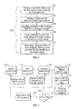
- a method of making a hydride batch 100 is also provided, as illustrated in FIG. 2 and with reference to FIG. 1 .
- the hydride assembling system 10 has been previously described and specific structural components need not be described in further detail.
- the method of making a hydride batch 100 includes winding 102 a wire onto the first spool 14, wherein the first spool is in close proximity to the hydrogen inlet 18.
- the heater section 32 is heated 104 above an ambient temperature.
- the method 100 also includes supplying hydrogen 106 to the hydrogen inlet 18 from the hydrogen plenum 20.
- the wire is fed 108 from the first spool 14 through the heater section 32 and toward the second spool 28 as the hydrogen is absorbed 110 within the wire during the feeding 108 of the wire from the first spool 14 toward the second spool 28.
- FIG. 3 depicts a flow diagram illustrating an embodiment comprising processes that the method 100 entails.
- the sensor tube assembly 12 is first mounted 112 to the first spool 14.
- a user may then interact with the GUI 38 to select 114 a specific identifier, such as a part number, that requires specific hydride properties.
- software of the GUI selects an initial feed rate 115 of the sensor tube assembly 12.
- an initial temperature of the heated section 32 is selected 117. Air within the sensor tube assembly 12 is then evacuated 116, as described above.
- the hydrogen plenum 20 is pressurized 118 to a pressure that will vary depending on the particular application, but in one embodiment the pressure ranges from about 100 psig to about 250 psig.
- the first valve 21 is opened 120 to introduce hydrogen to the hydrogen inlet 18 and therefore the sensor tube assembly 12.
- the quantity of hydrogen absorbed within the wire may be calculated 122.
- a determination 124 is made as to whether the quantity of hydrogen is within a desired range. If so 126, the process continues at the current feed rate. If not 128, the feed rate is adjusted with the feed speed controller 17. This closed loop process continues until the user halts the process.
Landscapes
- Chemical & Material Sciences (AREA)
- Engineering & Computer Science (AREA)
- Organic Chemistry (AREA)
- Chemical Kinetics & Catalysis (AREA)
- Mechanical Engineering (AREA)
- Combustion & Propulsion (AREA)
- Inorganic Chemistry (AREA)
- General Engineering & Computer Science (AREA)
- Materials Engineering (AREA)
- Metallurgy (AREA)
- Filling Or Discharging Of Gas Storage Vessels (AREA)
Abstract
Description
- The present invention relates to hydrides, and more particularly to a hydride assembling system, as well as a method of making a hydride batch.
- Hydrides have many uses and are formed in various configurations. They are typically constructed by inserting a wire into a tube to form a tube assembly. The tube assembly is immersed in a hydrogen atmosphere and heated to a temperature above an ambient temperature. In the elevated temperature environment, the wire absorbs the hydrogen, thus becoming a hydrided material. At typical ambient temperatures, hydrogen is trapped in the hydride material, but as the ambient temperature increases, the hydrided material outgases the hydrogen and increases the pressure in a surrounding volume. Such a characteristic is useful in certain applications, such as fire detection systems, for example.
- The assembly process commonly entails sealing one end of the tube assembly and introducing hydrogen to the other end in the heated condition. Unfortunately, such a process may lead to substantial non-uniformity of the hydrogen distribution along the length of the tube assembly. Additionally, by forming each hydride segment of a batch in an individual manner, the process is often slow and imprecise.
- According to one embodiment, a hydride assembling system includes a first spool configured to support a sensor tube assembly comprising a wire disposed within a sensor tube. Also included is a hydrogen inlet fluidly coupled to the first spool for providing hydrogen from a hydrogen plenum. Further included is a second spool configured to receive the sensor tube assembly as the sensor tube assembly is fed from the first spool. Yet further included is a heated section at a temperature above an ambient temperature and configured to heat the sensor tube assembly as the sensor tube assembly is fed through the heated section.
- According to another embodiment, a method of making a hydride batch is provided. The method includes winding a wire onto a first spool, the first spool in close proximity to a hydrogen inlet. The method also includes heating a heater section above an ambient temperature. The method further includes supplying hydrogen to the hydrogen inlet from a hydrogen plenum. The method yet further includes feeding the wire from the first spool through the heater section and toward a second spool. The method also includes absorbing hydrogen within the wire during the feeding of the wire from the first spool toward the second spool.
- The subject matter which is regarded as the invention is particularly pointed out and distinctly claimed in the claims at the conclusion of the specification. The foregoing and other features and advantages of the invention are apparent from the following detailed description taken in conjunction with the accompanying drawings in which:
-
FIG. 1 is a schematic illustration of a hydride assembling system; -
FIG. 2 is a flow diagram illustrating a method of making a hydride batch; and -
FIG. 3 is a flow diagram illustrating the method of making a hydride batch according to another aspect of the invention. - Referring to
FIG. 1 , a hydride assemblingsystem 10 is schematically illustrated. Thehydride assembling system 10 is employed to assemble hydride material comprising asensor tube assembly 12. Thesensor tube assembly 12 includes a wire that is inserted into a sensor tube and disposed therein. The wire and the sensor tube may be formed of various materials. In one embodiment, the wire comprises a metal (e.g., titanium) and the sensor tube comprises a stainless steel tube. Once hydrided, thesensor tube assembly 12 may be used in conjunction with numerous systems. One such system is a pneumatic fire detector for use on an aircraft. In particular, thesensor tube assembly 12 may be used in an aircraft engine for detection of fires therein. However, an aircraft is merely an exemplary application and it is to be appreciated that thesensor tube assembly 12 may be employed in numerous alternative applications. - As noted above, the
hydride assembling system 10 is used to continuously produce a batch of stock hydrided material. Thehydride assembling system 10 includes afirst spool 14 that is configured to support a previously constructed length of thesensor tube assembly 12. In particular, thesensor tube assembly 12 is wound onto thefirst spool 14 and arranged to be fed away from thefirst spool 14 in adirection 15 with aroller assembly 16 comprising a system of rollers and guides. Theroller assembly 16 is controlled by a feed speed controller 17 to adjust the feed speed of thesensor tube assembly 12. Proximate thefirst spool 14 is ahydrogen inlet 18 that is fluidly coupled to ahydrogen plenum 20 that contains a hydrogen supply at a controllable pressure. Thehydrogen inlet 18 is configured to introduce hydrogen to a location proximate thefirst spool 14 in a manner that provides hydrogen to thesensor tube assembly 12. In one embodiment, an end of thesensor tube assembly 12 is directly coupled to thehydrogen inlet 18 to introduce hydrogen directly into the end of thesensor tube assembly 12. The flow rate and amount of hydrogen supplied via thehydrogen inlet 18 is regulated with afirst valve 21, such as a solenoid valve that may open and close in a pulsed manner. - The
hydrogen plenum 20 is in fluid communication with ahydrogen tank 22 that is configured to supply thehydrogen plenum 20 with hydrogen gas, as needed. As shown, the pressure of the hydrogen supplied from thehydrogen tank 22 may be regulated with ahydrogen pressure regulator 24 before being routed to thehydrogen plenum 20, with asecond valve 26 controlling the flow rate of the hydrogen to thehydrogen plenum 20. In one embodiment, thesecond valve 26 comprises a solenoid valve. - The
hydride assembling system 10 includes asecond spool 28 that is configured to receive and support thesensor tube assembly 12 as it is fed away from thefirst spool 14. Disposed proximate thesecond spool 28 is avacuum component 30 that is configured to remove air from thesensor tube assembly 12. In addition to simply removing air, in one embodiment thevacuum component 30 may recycle hydrogen to thehydrogen tank 22 and/or thehydrogen plenum 20 during the hydriding process. As thesensor tube assembly 12 is fed along theroller assembly 16, thesensor tube assembly 12 is fed through aheated section 32 that is positioned between thefirst spool 14 and thesecond spool 28. Theheated section 32 comprises a section that is configured to heat thesensor tube assembly 12 during translation therealong. In one embodiment, theheated section 32 is a tubular section that is configured to allow thesensor tube assembly 12 to pass therethrough. The heatedsection 32 is controlled to a temperature that facilitates continuous absorption of hydrogen into the wire within thesensor tube assembly 12 as thesensor tube assembly 12 is drawn through theheated section 32. The precise temperature that is required to ensure continuous absorption will vary depending on thesensor tube assembly 12. Characteristics such as wire material and thickness, for example, are variables that will affect the necessary temperature. In one embodiment, the temperature is elevated to a temperature greater than about 300°C (about 572°F). - Also dependent upon various characteristics of the wire, and more generally the
sensor tube assembly 12, is the desired amount of hydrogen to be absorbed into the wire. Specifically, a desired concentration of hydrogen, measured by volume and/or length of the wire, is dependent upon the particular application. To determine the amount of hydrogen absorbed by the wire, a pressure differential between a location of the wire proximate thefirst spool 14 and thesecond spool 28 is monitored. The pressure drop between these locations allows a user to calculate the mass of hydrogen absorbed into the wire. Monitoring of the pressure differential is facilitated by the inclusion of afirst pressure gauge 34 disposed proximate thefirst spool 14 and asecond pressure gauge 36 disposed proximate thesecond spool 28. - Several components of the
hydride assembling system 10 are monitored with a graphical user interface (GUI) 38 that is in operative communication with components of thehydride assembling system 10. Specifically, thehydride assembling system 10 may be employed to monitor thefirst pressure gauge 34, thesecond pressure gauge 36, thefirst valve 21, thesecond valve 26, theheated section 32, and/or the feed speed controller 17. By monitoring the above-referenced components, theGUI 38 is configured to control a plurality of operating characteristics of thehydride assembling system 10. Such characteristics include a feed rate of the wire, a temperature of theheated section 32, a pressure within thehydrogen plenum 20, and a flow rate of hydrogen flowing through thefirst valve 21 or thesecond valve 26. Monitoring and controlling these components and characteristics allows a user to modify operation of thehydride assembling system 10, as needed. Such control advantageously allows for continuous and consistent hydriding of thesensor tube assembly 12, thereby lowering production cost and time, as well as increasing hydrogen concentration uniformity throughout a length and/or volume of thesensor tube assembly 12. These benefits are obtained as a result of the above-described characteristics and parameters determining the amount of hydrogen absorbed and the ability of it to remain absorbed. - A method of making a
hydride batch 100 is also provided, as illustrated inFIG. 2 and with reference toFIG. 1 . Thehydride assembling system 10 has been previously described and specific structural components need not be described in further detail. The method of making ahydride batch 100 includes winding 102 a wire onto thefirst spool 14, wherein the first spool is in close proximity to thehydrogen inlet 18. Theheater section 32 is heated 104 above an ambient temperature. Themethod 100 also includes supplyinghydrogen 106 to thehydrogen inlet 18 from thehydrogen plenum 20. The wire is fed 108 from thefirst spool 14 through theheater section 32 and toward thesecond spool 28 as the hydrogen is absorbed 110 within the wire during the feeding 108 of the wire from thefirst spool 14 toward thesecond spool 28. - In addition to the general processes described above in conjunction with the method of making a
hydride batch 100,FIG. 3 depicts a flow diagram illustrating an embodiment comprising processes that themethod 100 entails. Specifically, thesensor tube assembly 12 is first mounted 112 to thefirst spool 14. A user may then interact with theGUI 38 to select 114 a specific identifier, such as a part number, that requires specific hydride properties. Based on this selection, software of the GUI selects aninitial feed rate 115 of thesensor tube assembly 12. Additionally, an initial temperature of theheated section 32 is selected 117. Air within thesensor tube assembly 12 is then evacuated 116, as described above. Thehydrogen plenum 20 is pressurized 118 to a pressure that will vary depending on the particular application, but in one embodiment the pressure ranges from about 100 psig to about 250 psig. Thefirst valve 21 is opened 120 to introduce hydrogen to thehydrogen inlet 18 and therefore thesensor tube assembly 12. By monitoring the pressure differential, the quantity of hydrogen absorbed within the wire may be calculated 122. At this point, adetermination 124 is made as to whether the quantity of hydrogen is within a desired range. If so 126, the process continues at the current feed rate. If not 128, the feed rate is adjusted with the feed speed controller 17. This closed loop process continues until the user halts the process. - While the invention has been described in detail in connection with only a limited number of embodiments, it should be readily understood that the invention is not limited to such disclosed embodiments. Rather, the invention can be modified to incorporate any number of variations, alterations, substitutions or equivalent arrangements not heretofore described, but which are commensurate with the spirit and scope of the invention. Additionally, while various embodiments of the invention have been described, it is to be understood that aspects of the invention may include only some of the described embodiments. Accordingly, the invention is not to be seen as limited by the foregoing description, but is only limited by the scope of the appended claims.
Claims (15)
- A hydride assembling system (10) comprising:a first spool (14) configured to support a sensor tube assembly (12) comprising a wire disposed within a sensor tube;a hydrogen inlet (18) fluidly coupled to the first spool (14) for providing hydrogen from a hydrogen plenum (20);a second spool (28) configured to receive the sensor tube assembly (12) as the sensor tube assembly is fed from the first spool (14); anda heated section (32) at a temperature above an ambient temperature and configured to heat the sensor tube assembly as the sensor tube assembly is fed through the heated section (32).
- The hydride assembling system of claim 1, further comprising:a first pressure gauge (34) disposed proximate the first spool (14); anda second pressure gauge (36) disposed proximate the second spool (28).
- The hydride assembling system of claim 1, further comprising a vacuum component disposed proximate the second spool and configured to remove air from the sensor tube assembly.
- The hydride assembling system of claim 1, further comprising a solenoid valve disposed between the hydrogen plenum (20) and the first spool (14) for regulating the supply of hydrogen to the hydrogen inlet (18).
- The hydride assembling system of claim 1, further comprising a graphical user interface (38) in operative communication with at least one component.
- The hydride assembling system of claim 5, wherein the at least one component comprises a pressure gauge, a solenoid valve, the heated section, and a feed speed controller.
- The hydride assembling system of claim 1, further comprising a roller assembly (16) configured to translate the sensor tube assembly.
- A method of making a hydride batch comprising:winding a wire onto a first spool (14), the first spool in close proximity to a hydrogen inlet (18);heating a heater section (32) above an ambient temperature;supplying hydrogen to the hydrogen inlet (18) from a hydrogen plenum (20);feeding the wire from the first spool (14) through the heater section and toward a second spool (28); andabsorbing hydrogen within the wire during the feeding of the wire from the first spool (14) toward the second spool (28).
- The method of claim 8, wherein feeding the wire comprises translating the wire along a roller assembly (16).
- The method of claim 8, further comprising inserting the wire within a sensor tube.
- The method of claim 10, further comprising vacuuming air from the sensor tube.
- The method of claim 11, wherein vacuuming air from the sensor tube comprises vacuuming with a vacuum component in fluid communication with the sensor tube at a location proximate the second spool (28).
- The method of claim 10, further comprising measuring a pressure drop of the sensor tube detected by a first pressure gauge disposed proximate the first spool and a second pressure gauge disposed proximate the second spool.
- The method of claim 13, further comprising determining a mass of hydrogen absorbed into the wire based on the measured pressure drop between the first pressure gauge and the second pressure gauge.
- The method of claim 8, further comprising monitoring a plurality of operating parameters with a graphical user interface (38).
Applications Claiming Priority (1)
| Application Number | Priority Date | Filing Date | Title |
|---|---|---|---|
| US13/852,746 US9315889B2 (en) | 2013-03-28 | 2013-03-28 | Hydride assembling system and method of making a hydride batch |
Publications (2)
| Publication Number | Publication Date |
|---|---|
| EP2784021A1 true EP2784021A1 (en) | 2014-10-01 |
| EP2784021B1 EP2784021B1 (en) | 2017-08-09 |
Family
ID=50828659
Family Applications (1)
| Application Number | Title | Priority Date | Filing Date |
|---|---|---|---|
| EP14162234.0A Active EP2784021B1 (en) | 2013-03-28 | 2014-03-28 | Hydride assembling system |
Country Status (6)
| Country | Link |
|---|---|
| US (1) | US9315889B2 (en) |
| EP (1) | EP2784021B1 (en) |
| CN (1) | CN104071750B (en) |
| BR (1) | BR102014007444A2 (en) |
| CA (1) | CA2847481A1 (en) |
| ES (1) | ES2638567T3 (en) |
Citations (4)
| Publication number | Priority date | Publication date | Assignee | Title |
|---|---|---|---|---|
| US3277860A (en) * | 1963-04-01 | 1966-10-11 | Jr John E Lindberg | Sensor for heat or temperature detection and fire detection |
| JPS61233298A (en) * | 1985-04-09 | 1986-10-17 | Taiji Tanigaki | Hydrogen occluding/releasing device |
| EP0708055A1 (en) * | 1994-09-26 | 1996-04-24 | Leda S.R.L. | A method for inducing metal systems to absorb large quantities of hydrogen and its isotopes, and equipment for carrying out the method |
| US6936185B1 (en) * | 1999-08-18 | 2005-08-30 | Hydro-Quebec | Metal hydride bands and use thereof for storing hydrogen |
Family Cites Families (3)
| Publication number | Priority date | Publication date | Assignee | Title |
|---|---|---|---|---|
| US6680042B1 (en) * | 2000-11-07 | 2004-01-20 | Hydro-Quebec | Method of rapidly carrying out a hydrogenation of a hydrogen storage material |
| US20020088178A1 (en) * | 2001-01-10 | 2002-07-11 | Davis David Wayne | Hydrogen storage and generation system |
| WO2009089153A2 (en) * | 2008-01-04 | 2009-07-16 | University Of Florida Research Foundation, Inc. | Optical release of hydrogen from functionalized fullerenes as storage materials |
-
2013
- 2013-03-28 US US13/852,746 patent/US9315889B2/en active Active
-
2014
- 2014-03-25 CA CA2847481A patent/CA2847481A1/en not_active Abandoned
- 2014-03-27 BR BRBR102014007444-9A patent/BR102014007444A2/en not_active Application Discontinuation
- 2014-03-28 EP EP14162234.0A patent/EP2784021B1/en active Active
- 2014-03-28 CN CN201410121562.1A patent/CN104071750B/en active Active
- 2014-03-28 ES ES14162234.0T patent/ES2638567T3/en active Active
Patent Citations (4)
| Publication number | Priority date | Publication date | Assignee | Title |
|---|---|---|---|---|
| US3277860A (en) * | 1963-04-01 | 1966-10-11 | Jr John E Lindberg | Sensor for heat or temperature detection and fire detection |
| JPS61233298A (en) * | 1985-04-09 | 1986-10-17 | Taiji Tanigaki | Hydrogen occluding/releasing device |
| EP0708055A1 (en) * | 1994-09-26 | 1996-04-24 | Leda S.R.L. | A method for inducing metal systems to absorb large quantities of hydrogen and its isotopes, and equipment for carrying out the method |
| US6936185B1 (en) * | 1999-08-18 | 2005-08-30 | Hydro-Quebec | Metal hydride bands and use thereof for storing hydrogen |
Non-Patent Citations (1)
| Title |
|---|
| SANDROCK G S ET AL: "Applications", 1 January 1992, HYDROGEN IN INTERMETALLIC COMPOUNDS II, BERLIN, HEIDELBERG, NEW YORK : SPRINGER, DE, PAGE(S) 197 - 258, ISBN: 3-540-54668-5, XP008136481 * |
Also Published As
| Publication number | Publication date |
|---|---|
| EP2784021B1 (en) | 2017-08-09 |
| CA2847481A1 (en) | 2014-09-28 |
| CN104071750B (en) | 2017-04-19 |
| BR102014007444A2 (en) | 2014-12-02 |
| ES2638567T3 (en) | 2017-10-23 |
| CN104071750A (en) | 2014-10-01 |
| US9315889B2 (en) | 2016-04-19 |
| US20140290801A1 (en) | 2014-10-02 |
Similar Documents
| Publication | Publication Date | Title |
|---|---|---|
| JP5428755B2 (en) | Gas filling device | |
| US10150175B2 (en) | Gas systems, welding systems, and methods of welding | |
| US12465998B2 (en) | Volumetric plasma gas flow measurement and control system for metal-based wire-plasma arc additive manufacturing applications | |
| JP2010118652A5 (en) | ||
| CN101352814A (en) | Temperature control system for machine tool | |
| EP3990149A1 (en) | Powder supply system, method of operating a powder supply system and apparatus for producing a three-dimensional work piece | |
| US9315889B2 (en) | Hydride assembling system and method of making a hydride batch | |
| JP2013058066A (en) | Shield gas flow rate controller | |
| JP7771150B2 (en) | System and method for supplying acetylene | |
| CN114354833A (en) | Device and method for measuring oxidation kinetic parameters of reservoir fluid | |
| JP2013532265A5 (en) | ||
| US20240246099A1 (en) | Identiffying and quantifying components in a high-melting-point liquid | |
| JP5237644B2 (en) | Hydrogen amount measuring device | |
| JP6863457B2 (en) | Gas chromatograph | |
| JP2016057148A (en) | Gas chromatograph and flow controller used for the same | |
| EP1847812B1 (en) | Flow rate measuring method and flow rate measuring device | |
| KR101861549B1 (en) | Heat flow sensor for inspection of vacuum insulation material Heat flow detection device | |
| US2550126A (en) | Gas-generator system for producing heat-treating enveloping atmospheres | |
| CN108693282A (en) | The method of sampling for carrying out chromatography to headspace | |
| US20250020617A1 (en) | Gas chromatograph | |
| RU2462542C2 (en) | Method to straighten carbon yarn and plant for its realisation | |
| CN220619097U (en) | Evaporation cabinet for atmospheric pressure microwave plasma external vapor deposition process | |
| JP5247160B2 (en) | Hydrogen amount measuring device | |
| CN202038626U (en) | Device maintaining pressure of refrigerating fluid tank to be balanced | |
| CN106917185B (en) | A kind of braider weaving point temperature control equipment and control method |
Legal Events
| Date | Code | Title | Description |
|---|---|---|---|
| 17P | Request for examination filed |
Effective date: 20140328 |
|
| AK | Designated contracting states |
Kind code of ref document: A1 Designated state(s): AL AT BE BG CH CY CZ DE DK EE ES FI FR GB GR HR HU IE IS IT LI LT LU LV MC MK MT NL NO PL PT RO RS SE SI SK SM TR |
|
| AX | Request for extension of the european patent |
Extension state: BA ME |
|
| PUAI | Public reference made under article 153(3) epc to a published international application that has entered the european phase |
Free format text: ORIGINAL CODE: 0009012 |
|
| R17P | Request for examination filed (corrected) |
Effective date: 20150225 |
|
| RBV | Designated contracting states (corrected) |
Designated state(s): AL AT BE BG CH CY CZ DE DK EE ES FI FR GB GR HR HU IE IS IT LI LT LU LV MC MK MT NL NO PL PT RO RS SE SI SK SM TR |
|
| 17Q | First examination report despatched |
Effective date: 20160711 |
|
| STAA | Information on the status of an ep patent application or granted ep patent |
Free format text: STATUS: EXAMINATION IS IN PROGRESS |
|
| GRAP | Despatch of communication of intention to grant a patent |
Free format text: ORIGINAL CODE: EPIDOSNIGR1 |
|
| STAA | Information on the status of an ep patent application or granted ep patent |
Free format text: STATUS: GRANT OF PATENT IS INTENDED |
|
| INTG | Intention to grant announced |
Effective date: 20170223 |
|
| GRAS | Grant fee paid |
Free format text: ORIGINAL CODE: EPIDOSNIGR3 |
|
| GRAA | (expected) grant |
Free format text: ORIGINAL CODE: 0009210 |
|
| STAA | Information on the status of an ep patent application or granted ep patent |
Free format text: STATUS: THE PATENT HAS BEEN GRANTED |
|
| AK | Designated contracting states |
Kind code of ref document: B1 Designated state(s): AL AT BE BG CH CY CZ DE DK EE ES FI FR GB GR HR HU IE IS IT LI LT LU LV MC MK MT NL NO PL PT RO RS SE SI SK SM TR |
|
| REG | Reference to a national code |
Ref country code: GB Ref legal event code: FG4D |
|
| REG | Reference to a national code |
Ref country code: CH Ref legal event code: EP Ref country code: AT Ref legal event code: REF Ref document number: 916580 Country of ref document: AT Kind code of ref document: T Effective date: 20170815 |
|
| REG | Reference to a national code |
Ref country code: IE Ref legal event code: FG4D |
|
| REG | Reference to a national code |
Ref country code: DE Ref legal event code: R096 Ref document number: 602014012739 Country of ref document: DE |
|
| REG | Reference to a national code |
Ref country code: ES Ref legal event code: FG2A Ref document number: 2638567 Country of ref document: ES Kind code of ref document: T3 Effective date: 20171023 |
|
| REG | Reference to a national code |
Ref country code: NL Ref legal event code: MP Effective date: 20170809 |
|
| REG | Reference to a national code |
Ref country code: LT Ref legal event code: MG4D |
|
| REG | Reference to a national code |
Ref country code: AT Ref legal event code: MK05 Ref document number: 916580 Country of ref document: AT Kind code of ref document: T Effective date: 20170809 |
|
| PG25 | Lapsed in a contracting state [announced via postgrant information from national office to epo] |
Ref country code: SE Free format text: LAPSE BECAUSE OF FAILURE TO SUBMIT A TRANSLATION OF THE DESCRIPTION OR TO PAY THE FEE WITHIN THE PRESCRIBED TIME-LIMIT Effective date: 20170809 Ref country code: HR Free format text: LAPSE BECAUSE OF FAILURE TO SUBMIT A TRANSLATION OF THE DESCRIPTION OR TO PAY THE FEE WITHIN THE PRESCRIBED TIME-LIMIT Effective date: 20170809 Ref country code: FI Free format text: LAPSE BECAUSE OF FAILURE TO SUBMIT A TRANSLATION OF THE DESCRIPTION OR TO PAY THE FEE WITHIN THE PRESCRIBED TIME-LIMIT Effective date: 20170809 Ref country code: AT Free format text: LAPSE BECAUSE OF FAILURE TO SUBMIT A TRANSLATION OF THE DESCRIPTION OR TO PAY THE FEE WITHIN THE PRESCRIBED TIME-LIMIT Effective date: 20170809 Ref country code: NO Free format text: LAPSE BECAUSE OF FAILURE TO SUBMIT A TRANSLATION OF THE DESCRIPTION OR TO PAY THE FEE WITHIN THE PRESCRIBED TIME-LIMIT Effective date: 20171109 Ref country code: NL Free format text: LAPSE BECAUSE OF FAILURE TO SUBMIT A TRANSLATION OF THE DESCRIPTION OR TO PAY THE FEE WITHIN THE PRESCRIBED TIME-LIMIT Effective date: 20170809 Ref country code: LT Free format text: LAPSE BECAUSE OF FAILURE TO SUBMIT A TRANSLATION OF THE DESCRIPTION OR TO PAY THE FEE WITHIN THE PRESCRIBED TIME-LIMIT Effective date: 20170809 |
|
| REG | Reference to a national code |
Ref country code: FR Ref legal event code: PLFP Year of fee payment: 5 |
|
| PG25 | Lapsed in a contracting state [announced via postgrant information from national office to epo] |
Ref country code: BG Free format text: LAPSE BECAUSE OF FAILURE TO SUBMIT A TRANSLATION OF THE DESCRIPTION OR TO PAY THE FEE WITHIN THE PRESCRIBED TIME-LIMIT Effective date: 20171109 Ref country code: IS Free format text: LAPSE BECAUSE OF FAILURE TO SUBMIT A TRANSLATION OF THE DESCRIPTION OR TO PAY THE FEE WITHIN THE PRESCRIBED TIME-LIMIT Effective date: 20171209 Ref country code: GR Free format text: LAPSE BECAUSE OF FAILURE TO SUBMIT A TRANSLATION OF THE DESCRIPTION OR TO PAY THE FEE WITHIN THE PRESCRIBED TIME-LIMIT Effective date: 20171110 Ref country code: LV Free format text: LAPSE BECAUSE OF FAILURE TO SUBMIT A TRANSLATION OF THE DESCRIPTION OR TO PAY THE FEE WITHIN THE PRESCRIBED TIME-LIMIT Effective date: 20170809 Ref country code: PL Free format text: LAPSE BECAUSE OF FAILURE TO SUBMIT A TRANSLATION OF THE DESCRIPTION OR TO PAY THE FEE WITHIN THE PRESCRIBED TIME-LIMIT Effective date: 20170809 Ref country code: RS Free format text: LAPSE BECAUSE OF FAILURE TO SUBMIT A TRANSLATION OF THE DESCRIPTION OR TO PAY THE FEE WITHIN THE PRESCRIBED TIME-LIMIT Effective date: 20170809 |
|
| PG25 | Lapsed in a contracting state [announced via postgrant information from national office to epo] |
Ref country code: CZ Free format text: LAPSE BECAUSE OF FAILURE TO SUBMIT A TRANSLATION OF THE DESCRIPTION OR TO PAY THE FEE WITHIN THE PRESCRIBED TIME-LIMIT Effective date: 20170809 Ref country code: RO Free format text: LAPSE BECAUSE OF FAILURE TO SUBMIT A TRANSLATION OF THE DESCRIPTION OR TO PAY THE FEE WITHIN THE PRESCRIBED TIME-LIMIT Effective date: 20170809 Ref country code: DK Free format text: LAPSE BECAUSE OF FAILURE TO SUBMIT A TRANSLATION OF THE DESCRIPTION OR TO PAY THE FEE WITHIN THE PRESCRIBED TIME-LIMIT Effective date: 20170809 |
|
| REG | Reference to a national code |
Ref country code: DE Ref legal event code: R097 Ref document number: 602014012739 Country of ref document: DE |
|
| PG25 | Lapsed in a contracting state [announced via postgrant information from national office to epo] |
Ref country code: SM Free format text: LAPSE BECAUSE OF FAILURE TO SUBMIT A TRANSLATION OF THE DESCRIPTION OR TO PAY THE FEE WITHIN THE PRESCRIBED TIME-LIMIT Effective date: 20170809 Ref country code: EE Free format text: LAPSE BECAUSE OF FAILURE TO SUBMIT A TRANSLATION OF THE DESCRIPTION OR TO PAY THE FEE WITHIN THE PRESCRIBED TIME-LIMIT Effective date: 20170809 Ref country code: IT Free format text: LAPSE BECAUSE OF FAILURE TO SUBMIT A TRANSLATION OF THE DESCRIPTION OR TO PAY THE FEE WITHIN THE PRESCRIBED TIME-LIMIT Effective date: 20170809 Ref country code: SK Free format text: LAPSE BECAUSE OF FAILURE TO SUBMIT A TRANSLATION OF THE DESCRIPTION OR TO PAY THE FEE WITHIN THE PRESCRIBED TIME-LIMIT Effective date: 20170809 |
|
| PLBE | No opposition filed within time limit |
Free format text: ORIGINAL CODE: 0009261 |
|
| STAA | Information on the status of an ep patent application or granted ep patent |
Free format text: STATUS: NO OPPOSITION FILED WITHIN TIME LIMIT |
|
| 26N | No opposition filed |
Effective date: 20180511 |
|
| PG25 | Lapsed in a contracting state [announced via postgrant information from national office to epo] |
Ref country code: SI Free format text: LAPSE BECAUSE OF FAILURE TO SUBMIT A TRANSLATION OF THE DESCRIPTION OR TO PAY THE FEE WITHIN THE PRESCRIBED TIME-LIMIT Effective date: 20170809 |
|
| REG | Reference to a national code |
Ref country code: CH Ref legal event code: PL |
|
| PG25 | Lapsed in a contracting state [announced via postgrant information from national office to epo] |
Ref country code: MC Free format text: LAPSE BECAUSE OF FAILURE TO SUBMIT A TRANSLATION OF THE DESCRIPTION OR TO PAY THE FEE WITHIN THE PRESCRIBED TIME-LIMIT Effective date: 20170809 |
|
| REG | Reference to a national code |
Ref country code: BE Ref legal event code: MM Effective date: 20180331 |
|
| REG | Reference to a national code |
Ref country code: IE Ref legal event code: MM4A |
|
| PG25 | Lapsed in a contracting state [announced via postgrant information from national office to epo] |
Ref country code: LU Free format text: LAPSE BECAUSE OF NON-PAYMENT OF DUE FEES Effective date: 20180328 |
|
| PG25 | Lapsed in a contracting state [announced via postgrant information from national office to epo] |
Ref country code: IE Free format text: LAPSE BECAUSE OF NON-PAYMENT OF DUE FEES Effective date: 20180328 |
|
| PG25 | Lapsed in a contracting state [announced via postgrant information from national office to epo] |
Ref country code: LI Free format text: LAPSE BECAUSE OF NON-PAYMENT OF DUE FEES Effective date: 20180331 Ref country code: CH Free format text: LAPSE BECAUSE OF NON-PAYMENT OF DUE FEES Effective date: 20180331 Ref country code: BE Free format text: LAPSE BECAUSE OF NON-PAYMENT OF DUE FEES Effective date: 20180331 |
|
| PG25 | Lapsed in a contracting state [announced via postgrant information from national office to epo] |
Ref country code: MT Free format text: LAPSE BECAUSE OF NON-PAYMENT OF DUE FEES Effective date: 20180328 |
|
| PG25 | Lapsed in a contracting state [announced via postgrant information from national office to epo] |
Ref country code: TR Free format text: LAPSE BECAUSE OF FAILURE TO SUBMIT A TRANSLATION OF THE DESCRIPTION OR TO PAY THE FEE WITHIN THE PRESCRIBED TIME-LIMIT Effective date: 20170809 |
|
| PG25 | Lapsed in a contracting state [announced via postgrant information from national office to epo] |
Ref country code: PT Free format text: LAPSE BECAUSE OF FAILURE TO SUBMIT A TRANSLATION OF THE DESCRIPTION OR TO PAY THE FEE WITHIN THE PRESCRIBED TIME-LIMIT Effective date: 20170809 Ref country code: HU Free format text: LAPSE BECAUSE OF FAILURE TO SUBMIT A TRANSLATION OF THE DESCRIPTION OR TO PAY THE FEE WITHIN THE PRESCRIBED TIME-LIMIT; INVALID AB INITIO Effective date: 20140328 |
|
| PG25 | Lapsed in a contracting state [announced via postgrant information from national office to epo] |
Ref country code: CY Free format text: LAPSE BECAUSE OF FAILURE TO SUBMIT A TRANSLATION OF THE DESCRIPTION OR TO PAY THE FEE WITHIN THE PRESCRIBED TIME-LIMIT Effective date: 20170809 Ref country code: MK Free format text: LAPSE BECAUSE OF NON-PAYMENT OF DUE FEES Effective date: 20170809 |
|
| PG25 | Lapsed in a contracting state [announced via postgrant information from national office to epo] |
Ref country code: AL Free format text: LAPSE BECAUSE OF FAILURE TO SUBMIT A TRANSLATION OF THE DESCRIPTION OR TO PAY THE FEE WITHIN THE PRESCRIBED TIME-LIMIT Effective date: 20170809 |
|
| P01 | Opt-out of the competence of the unified patent court (upc) registered |
Effective date: 20230603 |
|
| PGFP | Annual fee paid to national office [announced via postgrant information from national office to epo] |
Ref country code: ES Payment date: 20250401 Year of fee payment: 12 |
|
| PGFP | Annual fee paid to national office [announced via postgrant information from national office to epo] |
Ref country code: GB Payment date: 20260220 Year of fee payment: 13 |
|
| PGFP | Annual fee paid to national office [announced via postgrant information from national office to epo] |
Ref country code: DE Payment date: 20260219 Year of fee payment: 13 |
|
| PGFP | Annual fee paid to national office [announced via postgrant information from national office to epo] |
Ref country code: FR Payment date: 20260219 Year of fee payment: 13 |