EP2783998A1 - Element for the storage, handling and transport of essentially sheet-form objects - Google Patents
Element for the storage, handling and transport of essentially sheet-form objects Download PDFInfo
- Publication number
- EP2783998A1 EP2783998A1 EP14075017.5A EP14075017A EP2783998A1 EP 2783998 A1 EP2783998 A1 EP 2783998A1 EP 14075017 A EP14075017 A EP 14075017A EP 2783998 A1 EP2783998 A1 EP 2783998A1
- Authority
- EP
- European Patent Office
- Prior art keywords
- height
- protrusions
- ribs
- sidelong
- equal
- Prior art date
- Legal status (The legal status is an assumption and is not a legal conclusion. Google has not performed a legal analysis and makes no representation as to the accuracy of the status listed.)
- Withdrawn
Links
- 101100334009 Caenorhabditis elegans rib-2 gene Proteins 0.000 description 5
- 239000011521 glass Substances 0.000 description 4
- 239000002023 wood Substances 0.000 description 4
- 230000005540 biological transmission Effects 0.000 description 2
- 239000002245 particle Substances 0.000 description 2
- 239000000919 ceramic Substances 0.000 description 1
- 238000010276 construction Methods 0.000 description 1
- 230000008878 coupling Effects 0.000 description 1
- 238000010168 coupling process Methods 0.000 description 1
- 238000005859 coupling reaction Methods 0.000 description 1
- 230000000694 effects Effects 0.000 description 1
- 238000004519 manufacturing process Methods 0.000 description 1
- 239000000463 material Substances 0.000 description 1
- 238000000034 method Methods 0.000 description 1
- -1 plates Substances 0.000 description 1
- 239000004576 sand Substances 0.000 description 1
- 230000035939 shock Effects 0.000 description 1
- 230000006641 stabilisation Effects 0.000 description 1
- 239000004575 stone Substances 0.000 description 1
Images



Classifications
-
- B—PERFORMING OPERATIONS; TRANSPORTING
- B65—CONVEYING; PACKING; STORING; HANDLING THIN OR FILAMENTARY MATERIAL
- B65D—CONTAINERS FOR STORAGE OR TRANSPORT OF ARTICLES OR MATERIALS, e.g. BAGS, BARRELS, BOTTLES, BOXES, CANS, CARTONS, CRATES, DRUMS, JARS, TANKS, HOPPERS, FORWARDING CONTAINERS; ACCESSORIES, CLOSURES, OR FITTINGS THEREFOR; PACKAGING ELEMENTS; PACKAGES
- B65D21/00—Nestable, stackable or joinable containers; Containers of variable capacity
- B65D21/02—Containers specially shaped, or provided with fittings or attachments, to facilitate nesting, stacking, or joining together
- B65D21/0201—Containers specially shaped, or provided with fittings or attachments, to facilitate nesting, stacking, or joining together stackable or joined together side-by-side
- B65D21/0202—Containers specially shaped, or provided with fittings or attachments, to facilitate nesting, stacking, or joining together stackable or joined together side-by-side and loosely interengaged by integral complementary shapes
-
- B—PERFORMING OPERATIONS; TRANSPORTING
- B65—CONVEYING; PACKING; STORING; HANDLING THIN OR FILAMENTARY MATERIAL
- B65D—CONTAINERS FOR STORAGE OR TRANSPORT OF ARTICLES OR MATERIALS, e.g. BAGS, BARRELS, BOTTLES, BOXES, CANS, CARTONS, CRATES, DRUMS, JARS, TANKS, HOPPERS, FORWARDING CONTAINERS; ACCESSORIES, CLOSURES, OR FITTINGS THEREFOR; PACKAGING ELEMENTS; PACKAGES
- B65D85/00—Containers, packaging elements or packages, specially adapted for particular articles or materials
- B65D85/30—Containers, packaging elements or packages, specially adapted for particular articles or materials for articles particularly sensitive to damage by shock or pressure
-
- A—HUMAN NECESSITIES
- A47—FURNITURE; DOMESTIC ARTICLES OR APPLIANCES; COFFEE MILLS; SPICE MILLS; SUCTION CLEANERS IN GENERAL
- A47F—SPECIAL FURNITURE, FITTINGS, OR ACCESSORIES FOR SHOPS, STOREHOUSES, BARS, RESTAURANTS OR THE LIKE; PAYING COUNTERS
- A47F7/00—Show stands, hangers, or shelves, adapted for particular articles or materials
- A47F7/0042—Show stands, hangers, or shelves, adapted for particular articles or materials for flat articles, e.g. panels, tiles
-
- B—PERFORMING OPERATIONS; TRANSPORTING
- B65—CONVEYING; PACKING; STORING; HANDLING THIN OR FILAMENTARY MATERIAL
- B65D—CONTAINERS FOR STORAGE OR TRANSPORT OF ARTICLES OR MATERIALS, e.g. BAGS, BARRELS, BOTTLES, BOXES, CANS, CARTONS, CRATES, DRUMS, JARS, TANKS, HOPPERS, FORWARDING CONTAINERS; ACCESSORIES, CLOSURES, OR FITTINGS THEREFOR; PACKAGING ELEMENTS; PACKAGES
- B65D85/00—Containers, packaging elements or packages, specially adapted for particular articles or materials
- B65D85/30—Containers, packaging elements or packages, specially adapted for particular articles or materials for articles particularly sensitive to damage by shock or pressure
- B65D85/48—Containers, packaging elements or packages, specially adapted for particular articles or materials for articles particularly sensitive to damage by shock or pressure for glass sheets
-
- B—PERFORMING OPERATIONS; TRANSPORTING
- B65—CONVEYING; PACKING; STORING; HANDLING THIN OR FILAMENTARY MATERIAL
- B65D—CONTAINERS FOR STORAGE OR TRANSPORT OF ARTICLES OR MATERIALS, e.g. BAGS, BARRELS, BOTTLES, BOXES, CANS, CARTONS, CRATES, DRUMS, JARS, TANKS, HOPPERS, FORWARDING CONTAINERS; ACCESSORIES, CLOSURES, OR FITTINGS THEREFOR; PACKAGING ELEMENTS; PACKAGES
- B65D19/00—Pallets or like platforms, with or without side walls, for supporting loads to be lifted or lowered
- B65D19/0004—Rigid pallets without side walls
- B65D19/0053—Rigid pallets without side walls the load supporting surface being made of more than one element
- B65D19/0077—Rigid pallets without side walls the load supporting surface being made of more than one element forming discontinuous or non-planar contact surfaces
- B65D19/0089—Rigid pallets without side walls the load supporting surface being made of more than one element forming discontinuous or non-planar contact surfaces the base surface being made of more than one element
- B65D19/0093—Rigid pallets without side walls the load supporting surface being made of more than one element forming discontinuous or non-planar contact surfaces the base surface being made of more than one element forming discontinuous or non-planar contact surfaces
- B65D19/0095—Rigid pallets without side walls the load supporting surface being made of more than one element forming discontinuous or non-planar contact surfaces the base surface being made of more than one element forming discontinuous or non-planar contact surfaces and each contact surface having a stringer-like shape
-
- B—PERFORMING OPERATIONS; TRANSPORTING
- B65—CONVEYING; PACKING; STORING; HANDLING THIN OR FILAMENTARY MATERIAL
- B65D—CONTAINERS FOR STORAGE OR TRANSPORT OF ARTICLES OR MATERIALS, e.g. BAGS, BARRELS, BOTTLES, BOXES, CANS, CARTONS, CRATES, DRUMS, JARS, TANKS, HOPPERS, FORWARDING CONTAINERS; ACCESSORIES, CLOSURES, OR FITTINGS THEREFOR; PACKAGING ELEMENTS; PACKAGES
- B65D19/00—Pallets or like platforms, with or without side walls, for supporting loads to be lifted or lowered
- B65D19/38—Details or accessories
- B65D19/44—Elements or devices for locating articles on platforms
-
- B—PERFORMING OPERATIONS; TRANSPORTING
- B65—CONVEYING; PACKING; STORING; HANDLING THIN OR FILAMENTARY MATERIAL
- B65D—CONTAINERS FOR STORAGE OR TRANSPORT OF ARTICLES OR MATERIALS, e.g. BAGS, BARRELS, BOTTLES, BOXES, CANS, CARTONS, CRATES, DRUMS, JARS, TANKS, HOPPERS, FORWARDING CONTAINERS; ACCESSORIES, CLOSURES, OR FITTINGS THEREFOR; PACKAGING ELEMENTS; PACKAGES
- B65D2519/00—Pallets or like platforms, with or without side walls, for supporting loads to be lifted or lowered
- B65D2519/00004—Details relating to pallets
- B65D2519/00009—Materials
- B65D2519/00014—Materials for the load supporting surface
- B65D2519/00029—Wood
-
- B—PERFORMING OPERATIONS; TRANSPORTING
- B65—CONVEYING; PACKING; STORING; HANDLING THIN OR FILAMENTARY MATERIAL
- B65D—CONTAINERS FOR STORAGE OR TRANSPORT OF ARTICLES OR MATERIALS, e.g. BAGS, BARRELS, BOTTLES, BOXES, CANS, CARTONS, CRATES, DRUMS, JARS, TANKS, HOPPERS, FORWARDING CONTAINERS; ACCESSORIES, CLOSURES, OR FITTINGS THEREFOR; PACKAGING ELEMENTS; PACKAGES
- B65D2519/00—Pallets or like platforms, with or without side walls, for supporting loads to be lifted or lowered
- B65D2519/00004—Details relating to pallets
- B65D2519/00009—Materials
- B65D2519/00049—Materials for the base surface
- B65D2519/00064—Wood
-
- B—PERFORMING OPERATIONS; TRANSPORTING
- B65—CONVEYING; PACKING; STORING; HANDLING THIN OR FILAMENTARY MATERIAL
- B65D—CONTAINERS FOR STORAGE OR TRANSPORT OF ARTICLES OR MATERIALS, e.g. BAGS, BARRELS, BOTTLES, BOXES, CANS, CARTONS, CRATES, DRUMS, JARS, TANKS, HOPPERS, FORWARDING CONTAINERS; ACCESSORIES, CLOSURES, OR FITTINGS THEREFOR; PACKAGING ELEMENTS; PACKAGES
- B65D2519/00—Pallets or like platforms, with or without side walls, for supporting loads to be lifted or lowered
- B65D2519/00004—Details relating to pallets
- B65D2519/00258—Overall construction
- B65D2519/00263—Overall construction of the pallet
- B65D2519/00273—Overall construction of the pallet made of more than one piece
-
- B—PERFORMING OPERATIONS; TRANSPORTING
- B65—CONVEYING; PACKING; STORING; HANDLING THIN OR FILAMENTARY MATERIAL
- B65D—CONTAINERS FOR STORAGE OR TRANSPORT OF ARTICLES OR MATERIALS, e.g. BAGS, BARRELS, BOTTLES, BOXES, CANS, CARTONS, CRATES, DRUMS, JARS, TANKS, HOPPERS, FORWARDING CONTAINERS; ACCESSORIES, CLOSURES, OR FITTINGS THEREFOR; PACKAGING ELEMENTS; PACKAGES
- B65D2519/00—Pallets or like platforms, with or without side walls, for supporting loads to be lifted or lowered
- B65D2519/00004—Details relating to pallets
- B65D2519/00258—Overall construction
- B65D2519/00283—Overall construction of the load supporting surface
- B65D2519/00293—Overall construction of the load supporting surface made of more than one piece
-
- B—PERFORMING OPERATIONS; TRANSPORTING
- B65—CONVEYING; PACKING; STORING; HANDLING THIN OR FILAMENTARY MATERIAL
- B65D—CONTAINERS FOR STORAGE OR TRANSPORT OF ARTICLES OR MATERIALS, e.g. BAGS, BARRELS, BOTTLES, BOXES, CANS, CARTONS, CRATES, DRUMS, JARS, TANKS, HOPPERS, FORWARDING CONTAINERS; ACCESSORIES, CLOSURES, OR FITTINGS THEREFOR; PACKAGING ELEMENTS; PACKAGES
- B65D2519/00—Pallets or like platforms, with or without side walls, for supporting loads to be lifted or lowered
- B65D2519/00004—Details relating to pallets
- B65D2519/00258—Overall construction
- B65D2519/00313—Overall construction of the base surface
- B65D2519/00323—Overall construction of the base surface made of more than one piece
-
- B—PERFORMING OPERATIONS; TRANSPORTING
- B65—CONVEYING; PACKING; STORING; HANDLING THIN OR FILAMENTARY MATERIAL
- B65D—CONTAINERS FOR STORAGE OR TRANSPORT OF ARTICLES OR MATERIALS, e.g. BAGS, BARRELS, BOTTLES, BOXES, CANS, CARTONS, CRATES, DRUMS, JARS, TANKS, HOPPERS, FORWARDING CONTAINERS; ACCESSORIES, CLOSURES, OR FITTINGS THEREFOR; PACKAGING ELEMENTS; PACKAGES
- B65D2519/00—Pallets or like platforms, with or without side walls, for supporting loads to be lifted or lowered
- B65D2519/00004—Details relating to pallets
- B65D2519/00258—Overall construction
- B65D2519/00313—Overall construction of the base surface
- B65D2519/00328—Overall construction of the base surface shape of the contact surface of the base
- B65D2519/00333—Overall construction of the base surface shape of the contact surface of the base contact surface having a stringer-like shape
-
- B—PERFORMING OPERATIONS; TRANSPORTING
- B65—CONVEYING; PACKING; STORING; HANDLING THIN OR FILAMENTARY MATERIAL
- B65D—CONTAINERS FOR STORAGE OR TRANSPORT OF ARTICLES OR MATERIALS, e.g. BAGS, BARRELS, BOTTLES, BOXES, CANS, CARTONS, CRATES, DRUMS, JARS, TANKS, HOPPERS, FORWARDING CONTAINERS; ACCESSORIES, CLOSURES, OR FITTINGS THEREFOR; PACKAGING ELEMENTS; PACKAGES
- B65D2519/00—Pallets or like platforms, with or without side walls, for supporting loads to be lifted or lowered
- B65D2519/00004—Details relating to pallets
- B65D2519/00547—Connections
- B65D2519/00552—Structures connecting the constitutive elements of the pallet to each other, i.e. load supporting surface, base surface and/or separate spacer
- B65D2519/00572—Structures connecting the constitutive elements of the pallet to each other, i.e. load supporting surface, base surface and/or separate spacer with separate auxiliary element, e.g. screws, nails, bayonets
-
- B—PERFORMING OPERATIONS; TRANSPORTING
- B65—CONVEYING; PACKING; STORING; HANDLING THIN OR FILAMENTARY MATERIAL
- B65D—CONTAINERS FOR STORAGE OR TRANSPORT OF ARTICLES OR MATERIALS, e.g. BAGS, BARRELS, BOTTLES, BOXES, CANS, CARTONS, CRATES, DRUMS, JARS, TANKS, HOPPERS, FORWARDING CONTAINERS; ACCESSORIES, CLOSURES, OR FITTINGS THEREFOR; PACKAGING ELEMENTS; PACKAGES
- B65D2519/00—Pallets or like platforms, with or without side walls, for supporting loads to be lifted or lowered
- B65D2519/00004—Details relating to pallets
- B65D2519/00736—Details
- B65D2519/00776—Accessories for manipulating the pallet
- B65D2519/00796—Guiding means for fork-lift
-
- B—PERFORMING OPERATIONS; TRANSPORTING
- B65—CONVEYING; PACKING; STORING; HANDLING THIN OR FILAMENTARY MATERIAL
- B65D—CONTAINERS FOR STORAGE OR TRANSPORT OF ARTICLES OR MATERIALS, e.g. BAGS, BARRELS, BOTTLES, BOXES, CANS, CARTONS, CRATES, DRUMS, JARS, TANKS, HOPPERS, FORWARDING CONTAINERS; ACCESSORIES, CLOSURES, OR FITTINGS THEREFOR; PACKAGING ELEMENTS; PACKAGES
- B65D2519/00—Pallets or like platforms, with or without side walls, for supporting loads to be lifted or lowered
- B65D2519/00004—Details relating to pallets
- B65D2519/00736—Details
- B65D2519/0081—Elements or devices for locating articles
- B65D2519/00815—Elements or devices for locating articles on the pallet
-
- B—PERFORMING OPERATIONS; TRANSPORTING
- B65—CONVEYING; PACKING; STORING; HANDLING THIN OR FILAMENTARY MATERIAL
- B65D—CONTAINERS FOR STORAGE OR TRANSPORT OF ARTICLES OR MATERIALS, e.g. BAGS, BARRELS, BOTTLES, BOXES, CANS, CARTONS, CRATES, DRUMS, JARS, TANKS, HOPPERS, FORWARDING CONTAINERS; ACCESSORIES, CLOSURES, OR FITTINGS THEREFOR; PACKAGING ELEMENTS; PACKAGES
- B65D85/00—Containers, packaging elements or packages, specially adapted for particular articles or materials
- B65D85/30—Containers, packaging elements or packages, specially adapted for particular articles or materials for articles particularly sensitive to damage by shock or pressure
- B65D85/46—Containers, packaging elements or packages, specially adapted for particular articles or materials for articles particularly sensitive to damage by shock or pressure for bricks, tiles or building blocks
Definitions
- the present invention relates to an element for the storage, handling and transport of objects.
- the invention relates to an element for the storage, handling and transport of fragile or easily damaged essentially flat objects, such as panes of glass, plates, tablets, tiles and similar of any material, such as natural stone, ceramic, glass, etc.
- the elements if they are small, are relatively light, such that they can be transported more cheaply and such that their own weight compared to the weight placed on them, which typically varies from approximately 500 kg to approximately 1500 kg, is minimised.
- the elements with their objects are also secured to a vehicle or a container. Because the objects are generally not strong enough, affixing the tie-down straps or similar over the objects must be avoided, but they have to run over a part of the elements where there are no objects.
- the tie-down straps thereby only exert a very limited downward force on elements that are between two elements, such that these elements can move relatively easily.
- the purpose of the invention is to provide a solution to at least one of the aforementioned and other disadvantages, by providing an element for the storage, handling and transport of objects, that comprises two or more ribs that extend at a mutual distance from one another in the width and height directions, whereby the element has two sides located opposite one another that are both provided with a sidelong connecting slat that extends in the longitudinal direction of the element, whereby at least one sidelong connecting slat has a top edge that is at a first height and at least one sidelong connecting slat has a bottom edge that is at a second height, whereby the ribs are connected together by means of the connecting slats, whereby the element is provided with one or more protrusions on one or both sides that protrudes or protrude sideways outside the sidelong connecting slat on this side and which has or have a bottom edge at a third height that is greater than or equal to the first height or has or have a top edge at a fourth height that is less than or equal to
- the resistance of the elements to all kinds of violent movements that can occur during transport is increased, such that with an equal construction of the element the weight of the load can be increased, or with an equal load a lighter and/or smaller element can be used.
- the difference between the third and the first height and/or the difference between the second and the fourth height is hereby less than 5 mm, more preferably less than 2 mm and even more preferably less than 1 mm.
- said one or more protrusions are on one or more ribs.
- the protrusions are an integral part of a rib.
- the element is provided on both sides with one or more of the said protrusions, whereby the said protrusions have a bottom edge on the first side at a third height that is greater than or equal to the first height of the top edge of the connecting slat at a second opposite side, and whereby the said protrusions on the second side have a top edge at a fourth height that is less than or equal to the second height of the bottom edge of the connecting slat on the first side.
- the element on the pallet trolley is higher than elements already in place, such that the protrusions on the elements cannot collide with the other elements and the sides of the elements can be neatly placed against one another, after which the element on the pallet trolley is lowered so that the protrusions and the sidelong connecting slats can act on one another with the transmission of forces.
- the element has at least two such protrusions on either side and at least one of the protrusions has a bottom edge on either side at a third height that is greater than or equal to the first height and at least one of the protrusions has a top edge at a fourth height that is less than or equal to the second height.
- the element 1 shown in figures 1 to 3 for placing sheet-form objects thereon is made of wood, for example multilayered sheets of wood, such as multiply, and has a length L of 1800 mm and a width B of 600 mm.
- the element 1 essentially consists of three sheet-form ribs 2 that extend in the height direction and width direction, and which each consists of a single piece of wood and of four connecting slats 3 that connect the ribs parallel to one another and at a distance from one another viewed in the longitudinal direction.
- the connecting slats 3 are affixed in recesses in the ribs 2. They extend in the longitudinal direction of the element 1 and protrude outside the ribs 2.
- the ribs 2 and connecting slats 3 are fastened together by means of combined pin/screw connectors, but other fastening methods are of course also possible.
- the ribs 2 each have two bearing edges 4 that extend essentially horizontally, but at a small angle ⁇ of 5° to a horizontal line, such that they make an upward-oriented angle to one another of 170°.
- each rib 2 runs parallel to the bearing edges 4 of the other ribs 2.
- the ribs 2 also have two supporting edges 5, that are each perpendicular to a bearing edge 4.
- the supporting edges 5 of a rib 2 together define a back section 6. Because the ribs 2 are identical, the supporting edges 5 of each rib 2 are parallel to the supporting edges 5 of the other ribs 2.
- the bearing edges 4 are not the same length, so that the centre of the back section 6 is approximately 15 mm next to the centre of the element 1.
- the ribs 2 have feet 7 on which the element 1 rests, and which ensure that there are clear spaces under the element 1 in which the forks of standard transport aids, such as a forklift truck or a pallet trolley for example, fit.
- Two of the connecting slats, 3A, 3B are at the sides 8, 9 of the element, i.e. one connecting slat 3A, 3B on each side 8,9.
- These sidelong connecting slats 3A, 3B have a thickness D v of 18 mm and a height H v of 92 mm.
- Its top edge 10 is at a first height H 1 of 186 mm and its bottom edge 11 has a second height H 2 of 94 mm above the underside of the element 1.
- a third connecting slat 3C is in the centre between the two sidelong connecting slats 3A, 3B, under the back section 6 of the ribs 2, and is affixed at such a height that its underside is also at the second height H 2 of 94 mm.
- a fourth connecting slat 3D is in a recess in one of the supporting edges 4 of each of the ribs 2.
- the ribs 2 are each provided with a protrusion 12 on a first side 8 of the element 1, that is an integral part of the rib 2, thus made from the same sheet of wood, and which is above the recess 13 for the sidelong connecting slat 3A on the first side, and fits in this recess 13.
- each of the protrusions 12 on the first side 8 are at a third height H 3 187.5 mm, thus 0.5 mm above the first height H 1 . This difference is so small that it cannot be seen in the drawings.
- the ribs 2 are each provided with a protrusion 15, that is also an integral part of the rib 2, and which is under the recess 13 for the sidelong connecting slat 3B on the second side 9, and fits in this recess 13.
- each of the protrusions 15 on the second side 9 is at a fourth height H 4 of 93.5 mm, thus 0.5 mm below the second height H 2 . This difference is so small that it cannot be seen in the drawings.
- the protrusions 12, 15 protrude over a distance of 15 mm outside the sidelong connecting slat 3A, 3B on the same side.
- a first element 1A is first positioned, using a pallet trolley 17 for example, whereby the positioning direction is in the direction from the second side 9 to the first side 8, and corresponds to the driving direction of the lorry. This direction is indicated by the arrow P.
- a second identical element 1B is positioned, in the same positioning direction, also using a pallet trolley 17.
- the pallet trolley 17 lifts the element 1B via the sidelong connecting slat 3B on the second side 9 and the third connecting slat 3C. As a result no part of the pallet trolley 17 protrudes outside the first side 8, so that the second element 1B can be placed exactly against the first element 1A.
- the second element 1B is driven with its first side 8 against the second side 9 of the first element 1A. This is done in a slightly displaced position compared to the first element 1A, so that the ribs 2 of the two elements 1A, 1B are not in line with one another. This is especially clear from figure 6 .
- the protrusions 12 on the first side 8 of the second element 1B are substantially higher than the sidelong connecting slats 3A, 3B of the first element 1A, and the sidelong connecting slats 3A, 3B of the second element 1B are substantially higher than the protrusions 15 on the second side 9 of the first element 1A, so that the said protrusions 12, 15 do not impede the accurate positioning of the second element 1B against the first element 1A with their sidelong connecting slats 3A, 3B against one another.
- the protrusions 15 on the second side 9 of the first element 1A are now under the sidelong connecting slat 3A on the first side 8 of the second element 1B, and the protrusions 12 on the first side 8 of the second element 1B are above the sidelong connecting slat 3B on the second side 9 of the first element 1A, in both cases with a gap in between of only 0.5 mm.
- a third element 1C is now positioned, whereby this third element 1A is again displaced slightly in the longitudinal direction L with respect to the second element 1B, and such that the ribs 2 of the third element 1C are in line with the ribs 2 of the first element 1A.
- the elements 1A, 1B, 1C can be secured, for example by means of straps or belts over the protruding parts of the sidelong connecting slats 3A, whereby little downward force is exerted on the second element 1B.
- the alternative element 1 of figure 9 differs from the element 1 described above by all ribs 2 being provided on both sides 8,9 with first protrusions 12 and second protrusions 15.
- this alternative element 1 is similar to the element 1 described above, with the difference that elements 1 cannot be placed next to one another with a good fit with a pallet trolley 17, because then protrusions 12, 15 collide against a sidelong connecting slat 3A,3B.
- the protrusions 12, 15 can be above the connecting slats on both sides 8, 9, or below the connecting slats 3A, 3B on both sides 8, 9.
- the protrusions 12, 15 could also not be at the ribs 2, but on another component of the element 1 and the number of protrusions 12,15 is not fixed. A single protrusion will also provide an effect.
- the sidelong connecting slats 3A, 3B, and thereby also the protrusions 12, 15 are not necessarily at the same height on both sides 8, 9.
Landscapes
- Engineering & Computer Science (AREA)
- Mechanical Engineering (AREA)
- Pallets (AREA)
Abstract
1.- Element (1) for transporting objects, that has ribs (2) at a distance from one another and two sides (8,9), each with a connecting slat (3A, 3B) for the ribs, whereby a connecting slat (3A, 3B) has a top edge (10) at a first height (H1) and a connecting slat (3A, 3B) has a bottom edge (11) at a second height (H2), whereby the element (1) on one side (8,9) is provided with a protrusion (12, 15) that protrudes sideways outside the connecting slat (3A, 3B) on this side (8,9) and which has a bottom edge (14) at a third height (H3) that is greater than or equal to the first height (H1) or has a top edge (16) at a fourth height (H4) that is less than or equal to the second height (H2).
Description
- The present invention relates to an element for the storage, handling and transport of objects.
- More particularly the invention relates to an element for the storage, handling and transport of fragile or easily damaged essentially flat objects, such as panes of glass, plates, tablets, tiles and similar of any material, such as natural stone, ceramic, glass, etc.
- Damage, whether breakage or damage to a surface with a decorative finishing layer, must of course be avoided.
- When such objects are stacked flat for storage, handling or transport, they are relatively vulnerable to shocks that can occur during transport or handling, and to scratches that can occur by sliding the objects over one another.
- When there are hard particles between the objects, such as grains of sand or particles that have broken off from the objects themselves for example, the risk of damage is particularly high.
- With elements for the storage, handling and transport of objects, it is also important that they are made as cheaply as possible, because they are often only intended to be used once.
- For cost reasons, the elements must be made as small as possible for the load for which they are intended.
- Also the elements, if they are small, are relatively light, such that they can be transported more cheaply and such that their own weight compared to the weight placed on them, which typically varies from approximately 500 kg to approximately 1500 kg, is minimised.
- Nevertheless, it goes without saying that such elements have to satisfy the safety requirements, and they must not collapse or fall over in the event of sudden movements, which can occur for example during emergency manoeuvres of a vehicle in which the elements are transported.
- Hence the objects are normally fastened on the elements with tie-down straps or otherwise.
- The elements with their objects are also secured to a vehicle or a container. Because the objects are generally not strong enough, affixing the tie-down straps or similar over the objects must be avoided, but they have to run over a part of the elements where there are no objects.
- Such elements are described in
WO 2012/031340 , which satisfy all requirements: they are light but strong, and cheap to manufacture. - However, these elements have a disadvantage if a number of them are placed next to one another. Moreover, preferably one single tie-down strap is used to secure a number of elements in one go.
- The tie-down straps thereby only exert a very limited downward force on elements that are between two elements, such that these elements can move relatively easily.
- This in itself can cause damage to the objects when these elements move or tilt. Rather more so however, an element can collapse because upon violent external movements, the forces act in a direction that does not correspond to the direction in which the element can withstand the maximum forces, normally the vertical direction, or are not distributed evenly over the entire element.
- Hence the purpose of the invention is to provide a solution to at least one of the aforementioned and other disadvantages, by providing an element for the storage, handling and transport of objects, that comprises two or more ribs that extend at a mutual distance from one another in the width and height directions, whereby the element has two sides located opposite one another that are both provided with a sidelong connecting slat that extends in the longitudinal direction of the element, whereby at least one sidelong connecting slat has a top edge that is at a first height and at least one sidelong connecting slat has a bottom edge that is at a second height, whereby the ribs are connected together by means of the connecting slats, whereby the element is provided with one or more protrusions on one or both sides that protrudes or protrude sideways outside the sidelong connecting slat on this side and which has or have a bottom edge at a third height that is greater than or equal to the first height or has or have a top edge at a fourth height that is less than or equal to the second height, so that, when the element is placed sideways against an identical element, a protrusion or protrusions is or are above or below a sidelong connecting slat of the identical element.
- When such elements are used side-by-side, upon a first slight deformation or tilting, the protrusions of a first element and a sidelong connecting slat of another element will transmit vertical forces to one another, such that further movement of the elements, which ultimately could lead to the collapse of an element or toppling, is prevented.
- As a result, in brief the resistance of the elements to all kinds of violent movements that can occur during transport is increased, such that with an equal construction of the element the weight of the load can be increased, or with an equal load a lighter and/or smaller element can be used.
- Preferably the difference between the third and the first height and/or the difference between the second and the fourth height is hereby less than 5 mm, more preferably less than 2 mm and even more preferably less than 1 mm.
- As a result, in the event of a very slight deformation or movement, a transmission of force takes place, which moreover comes into being smoothly.
- In a further preferred embodiment the said one or more protrusions are on one or more ribs.
- Because the ribs bear the vertical forces, this gives the advantage that the action of the protrusions is the most direct, because the forces do not first have to be transferred from the ribs to other elements.
- In a further preferred embodiment the protrusions are an integral part of a rib. As a result, an element with protrusions is no more expensive or is barely more expensive than a conventional element.
- In a further preferred embodiment, the element is provided on both sides with one or more of the said protrusions, whereby the said protrusions have a bottom edge on the first side at a third height that is greater than or equal to the first height of the top edge of the connecting slat at a second opposite side, and whereby the said protrusions on the second side have a top edge at a fourth height that is less than or equal to the second height of the bottom edge of the connecting slat on the first side.
- This has the advantage that loaded elements can be easily and accurately positioned correctly with respect to one another by means of a pallet trolley, by placing elements on the pallet trolley and driving with the first side oriented in the drive direction.
- Hereby the element on the pallet trolley is higher than elements already in place, such that the protrusions on the elements cannot collide with the other elements and the sides of the elements can be neatly placed against one another, after which the element on the pallet trolley is lowered so that the protrusions and the sidelong connecting slats can act on one another with the transmission of forces.
- In another preferred embodiment the element has at least two such protrusions on either side and at least one of the protrusions has a bottom edge on either side at a third height that is greater than or equal to the first height and at least one of the protrusions has a top edge at a fourth height that is less than or equal to the second height.
- As a result upward-oriented and downward-oriented deformations are transferred to adjacent elements, such that the elements support one another in two directions, and thus a more stable positioning is obtained.
- With the intention of better showing the characteristics of the invention, a preferred embodiment of an element according to the invention is described hereinafter by way of an example, without any limiting nature, with reference to the accompanying drawings, wherein:
-
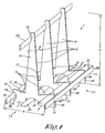
Figure 1 schematically shows a perspective view of an element according to the invention; -
figure 2 shows a side view according to arrow F2 of the element offigure 1 ; -
figure 3 shows a side view according to arrow F3 of the element offigure 1 ; -
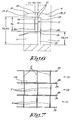
figures 4 and 5 show the use of elements according tofigure 1 ; -
figure 6 is a presentation of the part offigure 5 indicated with F6 on a larger scale and with more details; -
figure 7 is a top view of elements as shown infigure 5 with F6; -
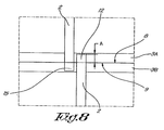
figure 8 is a presentation of the part offigure 7 indicated with F8 on a larger scale and with more details; -
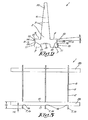
Figure 9 schematically shows a perspective view of an alternative element according to the invention; and -
Figures 10 and 11 respectively are presentations that correspond to the presentations infigures 6 and8 respectively and which concern the use of the element offigure 9 . - The element 1 shown in
figures 1 to 3 for placing sheet-form objects thereon is made of wood, for example multilayered sheets of wood, such as multiply, and has a length L of 1800 mm and a width B of 600 mm. - The element 1 essentially consists of three sheet-
form ribs 2 that extend in the height direction and width direction, and which each consists of a single piece of wood and of four connecting slats 3 that connect the ribs parallel to one another and at a distance from one another viewed in the longitudinal direction. - The connecting slats 3 are affixed in recesses in the
ribs 2. They extend in the longitudinal direction of the element 1 and protrude outside theribs 2. - The
ribs 2 and connecting slats 3 are fastened together by means of combined pin/screw connectors, but other fastening methods are of course also possible. - The
ribs 2 each have twobearing edges 4 that extend essentially horizontally, but at a small angle α of 5° to a horizontal line, such that they make an upward-oriented angle to one another of 170°. - The
bearing edges 4 of eachrib 2 run parallel to thebearing edges 4 of theother ribs 2. - The
ribs 2 also have two supportingedges 5, that are each perpendicular to abearing edge 4. The supportingedges 5 of arib 2 together define aback section 6. Because theribs 2 are identical, the supportingedges 5 of eachrib 2 are parallel to the supportingedges 5 of theother ribs 2. - The
bearing edges 4 are not the same length, so that the centre of theback section 6 is approximately 15 mm next to the centre of the element 1. - The
ribs 2 havefeet 7 on which the element 1 rests, and which ensure that there are clear spaces under the element 1 in which the forks of standard transport aids, such as a forklift truck or a pallet trolley for example, fit. - Two of the connecting slats, 3A, 3B are at the
sides slat side slats top edge 10 is at a first height H1 of 186 mm and itsbottom edge 11 has a second height H2 of 94 mm above the underside of the element 1. - A third connecting slat 3C is in the centre between the two sidelong connecting
slats back section 6 of theribs 2, and is affixed at such a height that its underside is also at the second height H2 of 94 mm. - A fourth connecting slat 3D is in a recess in one of the supporting
edges 4 of each of theribs 2. - The
ribs 2 are each provided with aprotrusion 12 on afirst side 8 of the element 1, that is an integral part of therib 2, thus made from the same sheet of wood, and which is above therecess 13 for the sidelong connectingslat 3A on the first side, and fits in thisrecess 13. - The
bottom edge 14 of each of theprotrusions 12 on thefirst side 8 are at a third height H3 187.5 mm, thus 0.5 mm above the first height H1. This difference is so small that it cannot be seen in the drawings. - On the second
opposite side 9 theribs 2 are each provided with aprotrusion 15, that is also an integral part of therib 2, and which is under therecess 13 for the sidelong connectingslat 3B on thesecond side 9, and fits in thisrecess 13. - The
top edge 16 of each of theprotrusions 15 on thesecond side 9 is at a fourth height H4 of 93.5 mm, thus 0.5 mm below the second height H2. This difference is so small that it cannot be seen in the drawings. - The
protrusions slat - The use of the element 1 described above is described hereinafter, with reference to
figures 4 to 8 . This use concerns the positioning of a number of elements 1, as is done in a lorry prior to transport for example. - Hereby, for clarity no objects placed on the elements are shown. However, in practice objects to be transported are placed on the elements 1 during use, for example panes of glass that are placed side-by-side, each with an edge on the bearing edges 4 and are thereby vertically supported, and which rest with a flat side against the supporting
edges 5, directly or via glass plates placed closer to the supportingedges 5 and are thereby supported sideways. - A
first element 1A is first positioned, using apallet trolley 17 for example, whereby the positioning direction is in the direction from thesecond side 9 to thefirst side 8, and corresponds to the driving direction of the lorry. This direction is indicated by the arrow P. - Then a second
identical element 1B is positioned, in the same positioning direction, also using apallet trolley 17. - Thanks to the fact that there is only a fourth connecting
slat 3D on one side of theback sections 6, the loader can easily select the correct orientation for each element 1. - The
pallet trolley 17 lifts theelement 1B via the sidelong connectingslat 3B on thesecond side 9 and the third connecting slat 3C. As a result no part of thepallet trolley 17 protrudes outside thefirst side 8, so that thesecond element 1B can be placed exactly against thefirst element 1A. - This situation is shown in
figure 4 . Thesecond element 1B is somewhat higher than thefirst element 1A, because thesecond element 1B is on thepallet trolley 17. - The
second element 1B is driven with itsfirst side 8 against thesecond side 9 of thefirst element 1A. This is done in a slightly displaced position compared to thefirst element 1A, so that theribs 2 of the twoelements figure 6 . - Due to the somewhat raised position of the
second element 1B, theprotrusions 12 on thefirst side 8 of thesecond element 1B are substantially higher than the sidelong connectingslats first element 1A, and the sidelong connectingslats second element 1B are substantially higher than theprotrusions 15 on thesecond side 9 of thefirst element 1A, so that the saidprotrusions second element 1B against thefirst element 1A with their sidelong connectingslats - Then the
element 1B can be lowered and thepallet trolley 17 removed. - The
protrusions 15 on thesecond side 9 of thefirst element 1A are now under the sidelong connectingslat 3A on thefirst side 8 of thesecond element 1B, and theprotrusions 12 on thefirst side 8 of thesecond element 1B are above the sidelong connectingslat 3B on thesecond side 9 of thefirst element 1A, in both cases with a gap in between of only 0.5 mm. - In an equivalent way a third element 1C is now positioned, whereby this
third element 1A is again displaced slightly in the longitudinal direction L with respect to thesecond element 1B, and such that theribs 2 of the third element 1C are in line with theribs 2 of thefirst element 1A. - The situation now obtained is shown in
figures 5 to 8 . It is clear that more elements 1 can be placed in an equivalent way, but for clarity only three elements 1 are used in this example. - Then the
elements slats 3A, whereby little downward force is exerted on thesecond element 1B. - If the vehicle in which the
elements feet 7 on thefirst side 8 of each of theelements elements - The
feet 7 on thesecond side 9 of allelements - In the first instance these forces will be coupled with slight deformations or movements of the
elements protrusions elements slats elements - More specifically, downward forces are hereby transmitted from the
first side 8 of theelements second side 9 of anotherelement elements elements elements - The alternative element 1 of
figure 9 differs from the element 1 described above by allribs 2 being provided on bothsides first protrusions 12 andsecond protrusions 15. - The use of this alternative element 1 is similar to the element 1 described above, with the difference that elements 1 cannot be placed next to one another with a good fit with a
pallet trolley 17, because then protrusions 12, 15 collide against a sidelong connectingslat - This means that two elements 1 are first brought close to one another with a
pallet trolley 17 and afterwards must be moved against one another as soon as they are at the same height. This turns out not to be a problem in practice. In order to facilitate this, thecorners 18 of the protrusions are somewhat rounded. - As is especially clear from
figure 10 , theprotrusions side slat - Different further alternative embodiments of the element described above are possible.
- For example, the
protrusions sides slats sides - This does not have any direct consequences on the stability that is obtained with the side-by-side positioning, but the positioning by means of a
pallet truck 17 is more difficult. - The
protrusions ribs 2, but on another component of the element 1 and the number ofprotrusions - The sidelong connecting
slats protrusions sides - An embodiment in which one or
more protrusions - The present invention is by no means limited to the embodiments described as an example and shown in the drawings, but an element according to the invention can be realised in all kinds of forms and dimensions, without departing from the scope of the invention.
Claims (15)
- Element (1) for the storage, handling and transport of objects, that comprises two or more ribs (2) that extend at a mutual distance from one another in the width and height directions, whereby the element (1) has two sides (8,9) located opposite one another that are both provided with a sidelong connecting slat (3A, 3B) that extends in the longitudinal direction (L) of the element (1), whereby at least one sidelong connecting slat (3A, 3B) has a top edge (10) that is at a first height (H1) and at least one sidelong connecting slat (3A, 3B) has a bottom edge (11) that is at a second height (H2), whereby the ribs (2) are connected together by means of the connecting slats (3A, 3B), characterised in that the element (1) is provided with one or more protrusions (12, 15) on one or both sides (8,9) that protrudes or protrude sideways outside the sidelong connecting slat (3A, 3B) on this side (8,9), and which has or have a bottom edge (14) at a third height (H3) that is greater than or equal to the first height (H1) or has or have a top edge (16) at a fourth height (H4) that is less than or equal to the second height (H2), so that, when the element (1) is placed sideways against an identical element (1), a protrusion or protrusions (12, 15) is or are above or below a sidelong connecting slat (3A, 3B) of the identical element (1).
- Element (1) according to claim 1, characterised in that the difference between the third height (H3) and the first height (H1) and/or the difference between the second height (H2) and the fourth height (H4) is less than 5 mm.
- Element (1) according to claim 1 or 2, characterised in that the said one or more protrusions (12, 15) is or are located on one or more ribs (2).
- Element (1) according to any one of the previous claims, characterised in that the said one or more protrusions (12, 15) is or are an integral part of a rib or ribs (2).
- Element (1) according to any one of the previous claims, characterised in that the said one or more protrusions (12, 15) protrudes or protrude sideways outside the sidelong connecting slat (3A, 3B) over a distance (A) that is less than or equal to twice the thickness (Dv) of the connecting slats (3A, 3B) but is greater than half of the thickness (Dv) of the connecting slats (3A, 3B).
- Element (1) according to any one of the previous claims, characterised in that it is provided on both sides (8, 9) with one or more of the said protrusions (12, 15).
- Element (1) according to claim 6, characterised in that the sidelong connecting slats (3A, 3B) are placed at the same height on both sides (8, 9) and are of the same size, viewed in a vertical cross-section.
- Element (1) according to claims 6 or 7, characterised in that all said protrusions (12, 15) have a bottom edge (14) at a third height (H3) that is greater than or equal to the first height (H1), or all said protrusions (12, 15) have a top edge (16) at a fourth height (H4) that is less than or equal to the second height (H2).
- Element (1) according to claims 6 or 7, characterised in that the said protrusions (12) have a bottom edge (14) on a first side (8) at a third height (H3) that is greater than or equal to the first height (H1) of the top edge (10) of the connecting slat (3B) on a second opposite side (9) and that the said protrusions (15) on the second side (9) have a top edge (16) at a fourth height (H4) that is less than or equal to the second height (H2) of the bottom edge (11) of the connecting slat (3A) on the first side (8).
- Element (1) according to any one of the previous claims, characterised in that the element (1) has at least two such protrusions (12, 15) on either side (8, 9) and that at least one of the protrusions (12, 15) on either side (8, 9) has a bottom edge (14) at a third height (H3) that is greater than or equal to the first height (H1) and at least one of the protrusions (12, 15) has a top edge (16) at a fourth height (H4) that is less than or equal to the second height (H2).
- Element (1) according to any one of the claims 1 to 9, characterised in that the element (1), on either side (8, 9) where it has the said one or more protrusions (12, 15), has at least two such protrusions (12, 15) and that the protrusions (12, 15) on a certain side (8,9) all have a bottom edge (14) at a third height (H3) that is greater than or equal to the first height (H1) or all have a top edge (16) at a fourth height (H4) that is less than or equal to the second height (H2).
- Element (1) according to any one of the previous claims, characterised in that it is provided with a third connecting slat (3C) that connects the ribs (2) together, that is between the two sidelong connecting slats (3A, 3B) and which extends parallel to them, whereby the underside of the two sidelong connecting slats (3A, 3B) and of the third connecting slat (3C) are at the same height (H2).
- Element (1) according to any one of the previous claims, characterised in that the ribs (2) each have a bearing edge (4) for the downward support of the objects, whereby the bearing edges (4) are in the same plane and in that the ribs (2) each have a supporting edge (5) for the sideways support of the objects, whereby the supporting edges (15) are in the same plane and perpendicular to the bearing edges (4).
- Element (1) according to claim 13, characterised in that the ribs (2) each have two bearing edges (4) that each have an incline, whereby the inclines of these two bearing edges (4) are such that they make an upward-oriented angle to one another that is less than 180°, and that the ribs (2) have a back section (6) on which there are two supporting edges (5) that are each perpendicular to a bearing edge (4) of the same rib (2).
- Element (1) according to claims 11 and 14, characterised in that the element is provided with a fourth connecting slat (3D) that connects the ribs (2) together, whereby this fourth connecting slat (3D) is in recesses in the supporting edges (5).
Applications Claiming Priority (1)
| Application Number | Priority Date | Filing Date | Title |
|---|---|---|---|
| BE2013/0209A BE1021416B1 (en) | 2013-03-26 | 2013-03-26 | ELEMENT FOR STORING, HANDLING AND TRANSPORTING MAINLY PLATE-MADE ITEMS |
Publications (1)
| Publication Number | Publication Date |
|---|---|
| EP2783998A1 true EP2783998A1 (en) | 2014-10-01 |
Family
ID=48482865
Family Applications (1)
| Application Number | Title | Priority Date | Filing Date |
|---|---|---|---|
| EP14075017.5A Withdrawn EP2783998A1 (en) | 2013-03-26 | 2014-03-13 | Element for the storage, handling and transport of essentially sheet-form objects |
Country Status (3)
| Country | Link |
|---|---|
| US (1) | US20140291187A1 (en) |
| EP (1) | EP2783998A1 (en) |
| BE (1) | BE1021416B1 (en) |
Cited By (3)
| Publication number | Priority date | Publication date | Assignee | Title |
|---|---|---|---|---|
| GB2531801B (en) * | 2014-10-31 | 2017-04-19 | Universal Road Marking Hand Tools Ltd | Paving slab support |
| CN109733740A (en) * | 2019-02-21 | 2019-05-10 | 彩虹(合肥)液晶玻璃有限公司 | A kind of A type frame plummer and liquid-crystalline glasses packing device |
| EP3922576A1 (en) | 2020-06-10 | 2021-12-15 | Deltarack Bvba | Support rack for storing or transporting plate-shaped objects, combination of a transport pallet and such a support rack, kit of parts for manufacturing such a support rack and use of such a support rack |
Families Citing this family (8)
| Publication number | Priority date | Publication date | Assignee | Title |
|---|---|---|---|---|
| DE202014103799U1 (en) * | 2014-08-15 | 2015-11-17 | Carsten Böttcher | Transport and / or storage rack and arrangement of a transport and / or storage rack on a base plate |
| US10336528B2 (en) * | 2016-12-30 | 2019-07-02 | Guardian Glass, LLC | Rail car rack |
| US10422179B2 (en) * | 2017-04-18 | 2019-09-24 | Goldfinch Brothers Inc. | Panel frame assembly, processing, transport, and installation system |
| PL3597564T3 (en) * | 2018-07-15 | 2021-07-26 | H.D. Duijts Holding B.V. | Stand system for arranging panels |
| CN112021881A (en) * | 2020-09-11 | 2020-12-04 | 广东全石石材供应链管理有限公司 | Stone material display device and stone material display system |
| US20220178494A1 (en) * | 2020-12-07 | 2022-06-09 | Richard M. Roche | Stand for Maintaining Panels of Sheet Material in a Vertical Orientation |
| BR202021018884U2 (en) * | 2021-09-22 | 2023-04-04 | Jean Bussolo Antunes | IMPROVEMENT IN SUPPORT FOR LOCKING CERAMIC COATINGS ON PALLETS |
| EP4640576A1 (en) * | 2022-12-21 | 2025-10-29 | Bussolo Antunes, Jean | Structural arrangement applied to a central support for flat articles |
Citations (3)
| Publication number | Priority date | Publication date | Assignee | Title |
|---|---|---|---|---|
| EP0462085A2 (en) * | 1990-06-12 | 1991-12-18 | Aktiebolaget Electrolux | Pallet |
| DE20011434U1 (en) * | 2000-07-05 | 2000-12-07 | Menger, Eduard, 42349 Wuppertal | Transport rack |
| WO2012031340A1 (en) | 2010-09-08 | 2012-03-15 | Parnass, Besloten Vennootschap Met Beperke Aansprakelijkheid | Element for the storage, treatment and transport of articles |
Family Cites Families (23)
| Publication number | Priority date | Publication date | Assignee | Title |
|---|---|---|---|---|
| US1836362A (en) * | 1925-04-27 | 1931-12-15 | Libbey Owens Ford Glass Co | Glass buck |
| US2116381A (en) * | 1936-06-16 | 1938-05-03 | Republic Steel Corp | Means for handling and shipping sheet metal |
| GB2024152B (en) * | 1978-06-30 | 1982-10-06 | Anglia Export Packing Ltd | Equipment-carrying cradle |
| US4382733A (en) * | 1978-11-02 | 1983-05-10 | Rodgers Kenneth G | Freight cradle with replaceable deformable cushioning insert |
| US4304336A (en) * | 1980-02-28 | 1981-12-08 | Mays Calvin B | Interchangeable glass rack for pickup trucks |
| US4512473A (en) * | 1982-12-02 | 1985-04-23 | Ppg Industries, Inc. | Adjustable shipping container for frangible sheet-like units |
| US4626017A (en) * | 1985-10-07 | 1986-12-02 | Robertson Paul E | Trailer structure for transporting sheet glass and frangible material |
| US5085329A (en) * | 1990-12-07 | 1992-02-04 | Crowell John W | Sheeting support |
| US5411360A (en) * | 1993-10-19 | 1995-05-02 | Libbey-Owens-Ford Co. | Apparatus for transporting sheet material |
| AT401258B (en) * | 1994-09-27 | 1996-07-25 | Lisec Peter | DEVICE FOR STORING GLASS PANELS OR INSULATING GLASS |
| US6910591B2 (en) * | 2001-11-15 | 2005-06-28 | Schneider National, Inc. | Transportable rack |
| US20030196971A1 (en) * | 2002-04-19 | 2003-10-23 | Jeskey Marion Michael | Foldable transport rack and methods of use thereof |
| JP3953896B2 (en) * | 2002-06-19 | 2007-08-08 | 日本板硝子株式会社 | Packing tool for plate |
| US6973882B2 (en) * | 2003-12-04 | 2005-12-13 | Sonoco Development, Inc. | Single use disposable pallet |
| US20060043032A1 (en) * | 2004-09-01 | 2006-03-02 | Mchugh Michael P | Modular rack and system of use |
| JP4924981B2 (en) * | 2006-12-07 | 2012-04-25 | 日本電気硝子株式会社 | Glass plate packing pallet and glass plate package |
| US7905183B2 (en) * | 2008-01-29 | 2011-03-15 | Gibson Daniel J | Structural cardboard runner, pallet, shipping article |
| US20130061784A1 (en) * | 2008-06-12 | 2013-03-14 | Green Line Armor, LLC | Pallet Support |
| US8752716B2 (en) * | 2009-10-28 | 2014-06-17 | Agc Flat Glass North America, Inc. | Export rack for sheet-like articles |
| US8376291B1 (en) * | 2010-01-08 | 2013-02-19 | Henry R. Groves | Foldable A-frame carrier |
| SE535026C2 (en) * | 2010-01-19 | 2012-03-20 | Green Wood Logistics Ab | load carriers |
| US8499700B2 (en) * | 2010-12-14 | 2013-08-06 | Barry Schumacher | Brace attachment for pallets |
| US8789710B1 (en) * | 2013-03-14 | 2014-07-29 | Moore Freight Service, Inc. | Glass sheet transport rack |
-
2013
- 2013-03-26 BE BE2013/0209A patent/BE1021416B1/en active
-
2014
- 2014-03-13 EP EP14075017.5A patent/EP2783998A1/en not_active Withdrawn
- 2014-03-24 US US14/223,396 patent/US20140291187A1/en not_active Abandoned
Patent Citations (3)
| Publication number | Priority date | Publication date | Assignee | Title |
|---|---|---|---|---|
| EP0462085A2 (en) * | 1990-06-12 | 1991-12-18 | Aktiebolaget Electrolux | Pallet |
| DE20011434U1 (en) * | 2000-07-05 | 2000-12-07 | Menger, Eduard, 42349 Wuppertal | Transport rack |
| WO2012031340A1 (en) | 2010-09-08 | 2012-03-15 | Parnass, Besloten Vennootschap Met Beperke Aansprakelijkheid | Element for the storage, treatment and transport of articles |
Cited By (5)
| Publication number | Priority date | Publication date | Assignee | Title |
|---|---|---|---|---|
| GB2531801B (en) * | 2014-10-31 | 2017-04-19 | Universal Road Marking Hand Tools Ltd | Paving slab support |
| CN109733740A (en) * | 2019-02-21 | 2019-05-10 | 彩虹(合肥)液晶玻璃有限公司 | A kind of A type frame plummer and liquid-crystalline glasses packing device |
| EP3922576A1 (en) | 2020-06-10 | 2021-12-15 | Deltarack Bvba | Support rack for storing or transporting plate-shaped objects, combination of a transport pallet and such a support rack, kit of parts for manufacturing such a support rack and use of such a support rack |
| BE1028389B1 (en) * | 2020-06-10 | 2022-01-18 | Deltarack Bvba | Carrier rack for storing or transporting plate-shaped objects, combination of a transport pallet and such a carrier rack, set of parts for manufacturing such a carrier rack and use of such a carrier rack |
| US11713161B2 (en) | 2020-06-10 | 2023-08-01 | Deltarack Bvba | Support rack for storing or transporting plate-shaped objects, combination of a transport pallet and such a support rack, kit of parts for manufacturing such a support rack and use of such a support rack |
Also Published As
| Publication number | Publication date |
|---|---|
| US20140291187A1 (en) | 2014-10-02 |
| BE1021416B1 (en) | 2015-11-18 |
Similar Documents
| Publication | Publication Date | Title |
|---|---|---|
| EP2783998A1 (en) | Element for the storage, handling and transport of essentially sheet-form objects | |
| CA2486257C (en) | Modular rack | |
| US10926921B2 (en) | Pallet shelf system and method of storing goods on a pallet shelf system | |
| AU2011328570B2 (en) | Auxiliary transport unit and method for use thereof | |
| EP2614008B1 (en) | Element for the storage, treatment and transport of articles | |
| US9394150B2 (en) | Cradle retainer for material handling | |
| US6708361B1 (en) | Container ramp | |
| CN101531284B (en) | Destacking device | |
| CN104284851A (en) | Stand for storing and/or transporting glass panels of large dimensions | |
| KR101809842B1 (en) | Pallet for transporting tire wheels of vehicle | |
| JP5168720B2 (en) | Glass plate pallet and glass plate package | |
| KR101498946B1 (en) | Aluminium alloy pallet | |
| KR101350171B1 (en) | The tire moving kit for loading container | |
| CN211365370U (en) | Tray for commodity circulation | |
| KR20120001565U (en) | Cargo loading pallet | |
| KR102218749B1 (en) | Pallet for Freight having Payload Drop-Preventing Structure | |
| KR20190136505A (en) | Equipped with support means Clamping lift for freight of glass plate | |
| KR102240360B1 (en) | Pallet for transporting glass | |
| CN219790835U (en) | Heavy-load composite tray | |
| KR102947126B1 (en) | Wooden box with built-in floating deck | |
| KR102947122B1 (en) | Wooden box with built-in floating deck | |
| KR102011037B1 (en) | Wood pallet with an advanced load capacity | |
| US10486873B2 (en) | Pallet-less brick | |
| JP2006347617A (en) | Wall surface structure of box-shaped container | |
| CN116674836A (en) | A multi-container loading vehicle frame |
Legal Events
| Date | Code | Title | Description |
|---|---|---|---|
| 17P | Request for examination filed |
Effective date: 20140313 |
|
| AK | Designated contracting states |
Kind code of ref document: A1 Designated state(s): AL AT BE BG CH CY CZ DE DK EE ES FI FR GB GR HR HU IE IS IT LI LT LU LV MC MK MT NL NO PL PT RO RS SE SI SK SM TR |
|
| AX | Request for extension of the european patent |
Extension state: BA ME |
|
| PUAI | Public reference made under article 153(3) epc to a published international application that has entered the european phase |
Free format text: ORIGINAL CODE: 0009012 |
|
| STAA | Information on the status of an ep patent application or granted ep patent |
Free format text: STATUS: THE APPLICATION IS DEEMED TO BE WITHDRAWN |
|
| 18D | Application deemed to be withdrawn |
Effective date: 20150402 |