EP2783986A2 - Hydraulic pump start system and method - Google Patents
Hydraulic pump start system and method Download PDFInfo
- Publication number
- EP2783986A2 EP2783986A2 EP14160961.0A EP14160961A EP2783986A2 EP 2783986 A2 EP2783986 A2 EP 2783986A2 EP 14160961 A EP14160961 A EP 14160961A EP 2783986 A2 EP2783986 A2 EP 2783986A2
- Authority
- EP
- European Patent Office
- Prior art keywords
- hydraulic motor
- motor pump
- contactor
- bus
- power unit
- Prior art date
- Legal status (The legal status is an assumption and is not a legal conclusion. Google has not performed a legal analysis and makes no representation as to the accuracy of the status listed.)
- Granted
Links
Images


Classifications
-
- F—MECHANICAL ENGINEERING; LIGHTING; HEATING; WEAPONS; BLASTING
- F15—FLUID-PRESSURE ACTUATORS; HYDRAULICS OR PNEUMATICS IN GENERAL
- F15B—SYSTEMS ACTING BY MEANS OF FLUIDS IN GENERAL; FLUID-PRESSURE ACTUATORS, e.g. SERVOMOTORS; DETAILS OF FLUID-PRESSURE SYSTEMS, NOT OTHERWISE PROVIDED FOR
- F15B20/00—Safety arrangements for fluid actuator systems; Applications of safety devices in fluid actuator systems; Emergency measures for fluid actuator systems
-
- B—PERFORMING OPERATIONS; TRANSPORTING
- B64—AIRCRAFT; AVIATION; COSMONAUTICS
- B64D—EQUIPMENT FOR FITTING IN OR TO AIRCRAFT; FLIGHT SUITS; PARACHUTES; ARRANGEMENT OR MOUNTING OF POWER PLANTS OR PROPULSION TRANSMISSIONS IN AIRCRAFT
- B64D41/00—Power installations for auxiliary purposes
-
- B—PERFORMING OPERATIONS; TRANSPORTING
- B64—AIRCRAFT; AVIATION; COSMONAUTICS
- B64D—EQUIPMENT FOR FITTING IN OR TO AIRCRAFT; FLIGHT SUITS; PARACHUTES; ARRANGEMENT OR MOUNTING OF POWER PLANTS OR PROPULSION TRANSMISSIONS IN AIRCRAFT
- B64D41/00—Power installations for auxiliary purposes
- B64D41/007—Ram air turbines
-
- F—MECHANICAL ENGINEERING; LIGHTING; HEATING; WEAPONS; BLASTING
- F02—COMBUSTION ENGINES; HOT-GAS OR COMBUSTION-PRODUCT ENGINE PLANTS
- F02C—GAS-TURBINE PLANTS; AIR INTAKES FOR JET-PROPULSION PLANTS; CONTROLLING FUEL SUPPLY IN AIR-BREATHING JET-PROPULSION PLANTS
- F02C7/00—Features, components parts, details or accessories, not provided for in, or of interest apart form groups F02C1/00 - F02C6/00; Air intakes for jet-propulsion plants
- F02C7/32—Arrangement, mounting, or driving, of auxiliaries
-
- B—PERFORMING OPERATIONS; TRANSPORTING
- B64—AIRCRAFT; AVIATION; COSMONAUTICS
- B64D—EQUIPMENT FOR FITTING IN OR TO AIRCRAFT; FLIGHT SUITS; PARACHUTES; ARRANGEMENT OR MOUNTING OF POWER PLANTS OR PROPULSION TRANSMISSIONS IN AIRCRAFT
- B64D2221/00—Electric power distribution systems onboard aircraft
-
- F—MECHANICAL ENGINEERING; LIGHTING; HEATING; WEAPONS; BLASTING
- F05—INDEXING SCHEMES RELATING TO ENGINES OR PUMPS IN VARIOUS SUBCLASSES OF CLASSES F01-F04
- F05D—INDEXING SCHEME FOR ASPECTS RELATING TO NON-POSITIVE-DISPLACEMENT MACHINES OR ENGINES, GAS-TURBINES OR JET-PROPULSION PLANTS
- F05D2220/00—Application
- F05D2220/30—Application in turbines
- F05D2220/34—Application in turbines in ram-air turbines ("RATS")
-
- F—MECHANICAL ENGINEERING; LIGHTING; HEATING; WEAPONS; BLASTING
- F05—INDEXING SCHEMES RELATING TO ENGINES OR PUMPS IN VARIOUS SUBCLASSES OF CLASSES F01-F04
- F05D—INDEXING SCHEME FOR ASPECTS RELATING TO NON-POSITIVE-DISPLACEMENT MACHINES OR ENGINES, GAS-TURBINES OR JET-PROPULSION PLANTS
- F05D2220/00—Application
- F05D2220/50—Application for auxiliary power units (APU's)
-
- F—MECHANICAL ENGINEERING; LIGHTING; HEATING; WEAPONS; BLASTING
- F05—INDEXING SCHEMES RELATING TO ENGINES OR PUMPS IN VARIOUS SUBCLASSES OF CLASSES F01-F04
- F05D—INDEXING SCHEME FOR ASPECTS RELATING TO NON-POSITIVE-DISPLACEMENT MACHINES OR ENGINES, GAS-TURBINES OR JET-PROPULSION PLANTS
- F05D2260/00—Function
- F05D2260/85—Starting
Definitions
- Aircraft hydraulic systems may be driven by one or more sources.
- output hydraulic power may be provided by engine driven sources 102 or (104) electric motor driven sources 106.
- the hydraulic power may be provided by the electric motor driven sources (e.g., pumps) 106.
- the engine driven sources 102 and the electric motor driven sources 106 may, in turn, be driven by other engines referred to in FIG. 1 as "main engines.”
- a Ram Air Turbine may be included.
- the RAT might not provide sufficient power to start the electric motor driven sources/pumps 106.
- the electric motor driven sources 106 may impose high current inrush and breakaway torque requirements at turn-on.
- an overload condition imposed on the RAT can have adverse effects on an emergency electric system, and may result in a loss of hydraulic power on the aircraft.
- the RAT could be sized to provide sufficient power, however doing so would result in additional weight being added to the aircraft.
- Embodiments are directed to a method for powering a hydraulic motor pump comprising: powering the hydraulic motor pump from a main bus when power is available from the main bus, powering the hydraulic motor pump from an auxiliary power unit starter motor controller during a start-up of the hydraulic motor pump when power from the main bus is unavailable, and powering the hydraulic motor pump from a generator different than the auxiliary power unit subsequent to starting-up the hydraulic motor pump.
- Embodiments are directed to a system comprising: a hydraulic motor pump configured to drive one or more hydraulic loads, a power bus configured to be selectively coupled to the hydraulic motor pump, a main bus configured to be selectively coupled to the power bus, a generator configured to be selectively coupled to the power bus, and an auxiliary power unit starter motor controller configured to selectively provide power to either the hydraulic motor pump or an auxiliary power unit.
- a hydraulic electric motor pump may be started by a motor controller, such as an auxiliary power unit (APU) starter motor controller.
- the APU motor controller may start the hydraulic electric motor pump using a battery as a power source.
- the hydraulic electric motor pump may be driven by (e.g., power for the hydraulic electric motor pump may be sourced from) a Ram Air Turbine (RAT) generator.
- RAT Ram Air Turbine
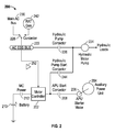
- FIG. 2 an exemplary aircraft system 200 in accordance with one or more embodiments is shown. The role and function of the various components and devices of the system 200 is described below in further detail.
- the system 200 may include a motor controller (MC) 202.
- the MC 202 may be used to source or provide power to an auxiliary power unit (APU) 204, by way of an APU starter motor 206.
- APU auxiliary power unit
- an APU start contactor 208 may be closed to couple the MC 202 to the APU starter motor 206.
- the power used to source the APU 204 may be derived from a battery 210.
- the battery 210 may be selectively coupled to the MC 202 based on a state of a MC power contactor 212.
- the MC power contactor 212 when the MC power contactor 212 is closed, power from the battery 210 may be coupled to the MC 202, and when the MC power contactor 212 is open, the battery 210 may be isolated from the MC 202.
- the APU start contactor 208 When the MC 202 is not providing power to the APU 204, the APU start contactor 208 may be opened to isolate the APU starter motor 206 from the MC 202.
- the APU 204 may be used to drive one or more loads. Typically, the APU 204 is used when an aircraft is on the ground, although the APU 204 can be used to drive loads during flight.
- the system 200 may include an aircraft essential bus (AC ESS BUS) 222.
- the AC ESS BUS 222 may be coupled to one or more loads deemed essential to flight, such as avionics, flight controls, and the like.
- the AC ESS BUS 222 may be used to provide power to a hydraulic motor pump 224, which in turn may power or drive one or more hydraulic loads, such as control surfaces on an aircraft.
- a hydraulic pump contactor 226 may be used to selectively couple the AC ESS BUS 222 and the hydraulic motor pump 224. When the hydraulic pump contactor 226 is closed, the AC ESS BUS 222 and the hydraulic motor pump 224 may be coupled to one another. When the hydraulic pump contactor 226 is open, the AC ESS BUS 222 may be isolated from the hydraulic motor pump 224.
- a switch or contactor 228 may be configured as shown in FIG. 2 to couple the ACC ESS BUS 222 to the Main AC BUS 230. Such a condition may be referred to as a so-called "normal mode" of operation, and the hydraulic motor pump 224 may receive electrical power via the Main AC BUS 230.
- a RAT generator (Gen) 242 may be engaged and the state of the contactor 228 may change such that the AC ESS BUS 222 may be coupled to the RAT Gen 242 (as opposed to the Main AC BUS 230). Such a condition may be referred to as a so-called "RAT Gen mode" of operation.
- the hydraulic motor pump 224 When first entering the RAT Gen mode of operation, the hydraulic motor pump 224 may be off, or may turn off as a result of the Main AC BUS 230 power being unavailable. When the hydraulic motor pump 224 is off the hydraulic motor pump 224 may represent or provide a low impedance that could subject a power source to a large in-rush current and/or startup torque that can exceed the capability of the source. To prevent a large in-rush current/startup torque being imposed on the RAT Gen 242, the hydraulic pump contactor 226 may be opened to isolate the AC ESS BUS (and hence, the RAT Gen 242) from the hydraulic motor pump 224.
- a hydraulic pump start contactor 244 may be closed and the MC power contactor 212 may be closed.
- the hydraulic motor pump 224 may be coupled to the battery 210 by way of the MC 202, and power from the battery 210 may be used to start the hydraulic motor pump 224.
- the MC 202 may optimize the starting of the hydraulic motor pump 224 using motor control techniques, such as constant voltage over frequency control.
- the APU start contactor 208 may be open to isolate the battery 210/MC 202 from the APU starter motor 206/APU 204.
- the MC 202 may be used to provide power to the APU starter motor 206/APU 204, and in this respect, the APU start contactor 208 may be closed. Moreover, once the hydraulic motor pump 224 is started, the hydraulic pump start contactor 244 may be opened to isolate the MC 202 from the hydraulic motor pump 224 and the hydraulic pump contactor 226 may be closed to power the hydraulic motor pump 224 from the RAT Gen 242 (via the AC ESS BUS 222).
- the hydraulic motor pump 224 may be started using power provided by the battery 210. Once the hydraulic motor pump 224 is up-and-running, the hydraulic motor pump 224 may be powered by the RAT Gen 242. In this manner, the output power capacity (and hence, the size and weight) of the RAT Gen 242 may be made less/smaller than if the RAT Gen 242 was required to provide sufficient power to start the hydraulic motor pump 224.
- the battery 210 and the MC 202 may be appropriately sized to facilitate starting the hydraulic motor pump 224.
- the timeframe for starting the hydraulic motor pump 224 is typically short (e.g., on the order of two to ten seconds).
- the MC 202's output characteristics may be matched or synchronized to the characteristics of the AC ESS BUS 222.
- the characteristics of the AC ESS BUS may be sensed or determined by a buffer or sensory device 252.
- the matching of the characteristics may be used to minimize the electrical disturbance when the input power source to the hydraulic motor pump 224 is switched, e.g., from the MC 202/battery 210 to the AC ESS BUS 222/RAT Gen 242.
- Minimizing the electrical disturbance may be used to protect one or more components, such as the hydraulic pump contactor 226, from being subjected to excessive voltages or currents.
- the method 300 may be used to selectively power a hydraulic motor pump (e.g., hydraulic motor pump 224).
- a hydraulic motor pump e.g., hydraulic motor pump 224
- the method 300 is described below in connection with the system 200 of FIG. 2 .
- the method 300 may be applied to or adapted for other systems, components, or devices.
- the hydraulic motor pump 224 may be powered by the Main AC BUS 230 via the AC ESS BUS 222.
- the RAT Gen 242 may be disengaged or turned-off, the hydraulic pump contactor 226 may be closed, the hydraulic pump start contactor 244 may be open, and the contactor 228 may be positioned to couple the ACC ESS BUS 222 to the Main AC BUS 230.
- the APU start contactor 208 and the MC power contactor 212 may be open; otherwise, if APU power is needed the APU start contactor 208 may be closed and the MC power contactor 212 may be closed.
- the hydraulic motor pump 224 may be powered by the MC 202/battery 210 in order to start-up or turn-on the hydraulic motor pump 224.
- the RAT Gen 242 may be engaged or turned-on, the hydraulic pump contactor 226 may be opened, the hydraulic pump start contactor 244 may be closed, the MC power contactor 212 may be closed, the APU start contractor 208 may be opened, and the contactor 228 may be positioned to couple the ACC ESS BUS 222 to the RAT Gen 242.
- the hydraulic motor pump 224 may be powered by the RAT Gen 242 via the AC ESS BUS 222.
- the hydraulic pump contactor 226 may be closed, and the hydraulic pump start contactor 244 may be opened.
- the APU start contactor 208 may be closed; otherwise, if APU power is not needed the MC power contactor 212 may be opened.
- Flow may remain in block 308 until Main AC BUS power is restored, at which point flow may proceed from block 308 to block 302.
- the method shown in FIG. 3 is illustrative. In some embodiments, one or more of the blocks or operations (or portions thereof) may be optional. In some embodiments, the blocks may execute in an order or sequence that is different from what is shown in FIG. 3 . In some embodiments, one or more additional blocks not shown may be included.
- Embodiments of the disclosure may be tied to one or more particular machines.
- a hydraulic electric motor pump may be driven by one or more sources or devices.
- the sources or devices may include a motor controller and a RAT generator.
- the hydraulic electric motor pump may receive power from one or more sources for purposes of starting or running the hydraulic electric motor pump.
- various functions or acts may take place at a given location and/or in connection with the operation of one or more apparatuses or systems.
- a portion of a given function or act may be performed at a first device or location, and the remainder of the function or act may be performed at one or more additional devices or locations.
- Embodiments of the disclosure may be directed to one or more systems, apparatuses, and/or methods.
- Embodiments of the disclosure may be implemented using hardware, software, firmware, or any combination thereof.
- a memory may store instructions that, when executed by at least one processor, cause an apparatus or system to perform one or more methodological acts, such as those described herein.
- a computer-readable medium e.g., a transitory and/or non-transitory medium
- the medium may include instructions that, when executed, cause an apparatus or system to perform one or more methodological acts, such as those described herein.
- various mechanical components known to those of skill in the art may be utilized.
Landscapes
- Engineering & Computer Science (AREA)
- Chemical & Material Sciences (AREA)
- Aviation & Aerospace Engineering (AREA)
- Combustion & Propulsion (AREA)
- Mechanical Engineering (AREA)
- General Engineering & Computer Science (AREA)
- Fluid Mechanics (AREA)
- Physics & Mathematics (AREA)
- Analytical Chemistry (AREA)
- Control Of Electric Motors In General (AREA)
- Fluid-Pressure Circuits (AREA)
- Control Of Positive-Displacement Pumps (AREA)
- Auxiliary Drives, Propulsion Controls, And Safety Devices (AREA)
Abstract
Description
- Aircraft hydraulic systems may be driven by one or more sources. For example, referring to
FIG. 1 , output hydraulic power may be provided by engine drivensources 102 or (104) electric motor drivensources 106. In the event of failure of unavailability of the engine driven sources (e.g., pumps) 102, the hydraulic power may be provided by the electric motor driven sources (e.g., pumps) 106. The engine drivensources 102 and the electric motor drivensources 106 may, in turn, be driven by other engines referred to inFIG. 1 as "main engines." - In order to provide an alternate source of electric power (e.g., in the event that the main engines fail or are unavailable), a Ram Air Turbine (RAT) may be included. In some instances (e.g., under some flight conditions), the RAT might not provide sufficient power to start the electric motor driven sources/
pumps 106. For example, the electric motor drivensources 106 may impose high current inrush and breakaway torque requirements at turn-on. As a result, an overload condition imposed on the RAT can have adverse effects on an emergency electric system, and may result in a loss of hydraulic power on the aircraft. Alternatively, the RAT could be sized to provide sufficient power, however doing so would result in additional weight being added to the aircraft. - Embodiments are directed to a method for powering a hydraulic motor pump comprising: powering the hydraulic motor pump from a main bus when power is available from the main bus, powering the hydraulic motor pump from an auxiliary power unit starter motor controller during a start-up of the hydraulic motor pump when power from the main bus is unavailable, and powering the hydraulic motor pump from a generator different than the auxiliary power unit subsequent to starting-up the hydraulic motor pump.
- Embodiments are directed to a system comprising: a hydraulic motor pump configured to drive one or more hydraulic loads, a power bus configured to be selectively coupled to the hydraulic motor pump, a main bus configured to be selectively coupled to the power bus, a generator configured to be selectively coupled to the power bus, and an auxiliary power unit starter motor controller configured to selectively provide power to either the hydraulic motor pump or an auxiliary power unit.
- Additional embodiments are described below.
- The present disclosure is illustrated by way of example and not limited in the accompanying Figures, in which:
-
FIG. 1 illustrates an aircraft hydraulic system in accordance with the prior art; -
FIG. 2 illustrates an aircraft system in accordance with one or more embodiments; and -
FIG. 3 illustrates an exemplary method in accordance with one or more embodiments of this disclosure. - It is noted that various connections are set forth between elements in the following description and in the drawings (the contents of which are included in this disclosure by way of reference). It is noted that these connections in general and, unless specified otherwise, may be direct or indirect and that this specification is not intended to be limiting in this respect. In this regard, a coupling of entities, components, and/or devices may refer to either a direct connection or an indirect connection.
- In accordance with various embodiments of the disclosure, a hydraulic electric motor pump may be started by a motor controller, such as an auxiliary power unit (APU) starter motor controller. The APU motor controller may start the hydraulic electric motor pump using a battery as a power source. Once the hydraulic electric motor pump is running, the hydraulic electric motor pump may be driven by (e.g., power for the hydraulic electric motor pump may be sourced from) a Ram Air Turbine (RAT) generator. In this manner, the RAT generator might not be overloaded during hydraulic electric motor pump starting, which may help to ensure that emergency electric system power and hydraulic power is available.
- Turning now to
FIG. 2 , anexemplary aircraft system 200 in accordance with one or more embodiments is shown. The role and function of the various components and devices of thesystem 200 is described below in further detail. - The
system 200 may include a motor controller (MC) 202. The MC 202 may be used to source or provide power to an auxiliary power unit (APU) 204, by way of anAPU starter motor 206. To facilitate such use, an APU startcontactor 208 may be closed to couple the MC 202 to the APUstarter motor 206. The power used to source the APU 204 may be derived from abattery 210. Thebattery 210 may be selectively coupled to theMC 202 based on a state of aMC power contactor 212. For example, when theMC power contactor 212 is closed, power from thebattery 210 may be coupled to theMC 202, and when theMC power contactor 212 is open, thebattery 210 may be isolated from the MC 202. When the MC 202 is not providing power to the APU 204, the APU startcontactor 208 may be opened to isolate the APUstarter motor 206 from the MC 202. - The APU 204 may be used to drive one or more loads. Typically, the APU 204 is used when an aircraft is on the ground, although the APU 204 can be used to drive loads during flight.
- The
system 200 may include an aircraft essential bus (AC ESS BUS) 222. The AC ESS BUS 222 may be coupled to one or more loads deemed essential to flight, such as avionics, flight controls, and the like. The AC ESS BUS 222 may be used to provide power to ahydraulic motor pump 224, which in turn may power or drive one or more hydraulic loads, such as control surfaces on an aircraft. Ahydraulic pump contactor 226 may be used to selectively couple the AC ESS BUS 222 and thehydraulic motor pump 224. When thehydraulic pump contactor 226 is closed, the AC ESS BUS 222 and thehydraulic motor pump 224 may be coupled to one another. When thehydraulic pump contactor 226 is open, the AC ESS BUS 222 may be isolated from thehydraulic motor pump 224. - When Main AC
BUS 230 power is available, a switch orcontactor 228 may be configured as shown inFIG. 2 to couple the ACCESS BUS 222 to theMain AC BUS 230. Such a condition may be referred to as a so-called "normal mode" of operation, and thehydraulic motor pump 224 may receive electrical power via the Main AC BUS 230. - When Main AC
BUS 230 power is unavailable (e.g., Main ACBUS 230 power is lost), a RAT generator (Gen) 242 may be engaged and the state of thecontactor 228 may change such that the AC ESS BUS 222 may be coupled to the RAT Gen 242 (as opposed to the Main AC BUS 230). Such a condition may be referred to as a so-called "RAT Gen mode" of operation. - When first entering the RAT Gen mode of operation, the
hydraulic motor pump 224 may be off, or may turn off as a result of the Main ACBUS 230 power being unavailable. When thehydraulic motor pump 224 is off thehydraulic motor pump 224 may represent or provide a low impedance that could subject a power source to a large in-rush current and/or startup torque that can exceed the capability of the source. To prevent a large in-rush current/startup torque being imposed on the RAT Gen 242, thehydraulic pump contactor 226 may be opened to isolate the AC ESS BUS (and hence, the RAT Gen 242) from thehydraulic motor pump 224. - To start the
hydraulic motor pump 224 in the RAT Gen mode of operation, a hydraulicpump start contactor 244 may be closed and theMC power contactor 212 may be closed. In this manner, thehydraulic motor pump 224 may be coupled to thebattery 210 by way of theMC 202, and power from thebattery 210 may be used to start thehydraulic motor pump 224. The MC 202 may optimize the starting of thehydraulic motor pump 224 using motor control techniques, such as constant voltage over frequency control. When starting the hydraulic motor pump, the APU startcontactor 208 may be open to isolate thebattery 210/MC 202 from the APUstarter motor 206/APU 204. - Once the
hydraulic motor pump 224 is started in the RAT Gen mode of operation, the MC 202 may be used to provide power to the APUstarter motor 206/APU 204, and in this respect, the APUstart contactor 208 may be closed. Moreover, once thehydraulic motor pump 224 is started, the hydraulicpump start contactor 244 may be opened to isolate the MC 202 from thehydraulic motor pump 224 and thehydraulic pump contactor 226 may be closed to power thehydraulic motor pump 224 from the RAT Gen 242 (via the AC ESS BUS 222). - Thus, as described above, the
hydraulic motor pump 224 may be started using power provided by thebattery 210. Once thehydraulic motor pump 224 is up-and-running, thehydraulic motor pump 224 may be powered by the RAT Gen 242. In this manner, the output power capacity (and hence, the size and weight) of the RAT Gen 242 may be made less/smaller than if the RAT Gen 242 was required to provide sufficient power to start thehydraulic motor pump 224. Thebattery 210 and the MC 202 may be appropriately sized to facilitate starting thehydraulic motor pump 224. The timeframe for starting thehydraulic motor pump 224 is typically short (e.g., on the order of two to ten seconds). - In some embodiments, the
MC 202's output characteristics (e.g., frequency, voltage, and phase) may be matched or synchronized to the characteristics of the ACESS BUS 222. The characteristics of the AC ESS BUS may be sensed or determined by a buffer orsensory device 252. The matching of the characteristics may be used to minimize the electrical disturbance when the input power source to thehydraulic motor pump 224 is switched, e.g., from theMC 202/battery 210 to the AC ESS BUS 222/RAT Gen 242. Minimizing the electrical disturbance may be used to protect one or more components, such as thehydraulic pump contactor 226, from being subjected to excessive voltages or currents. - Turning now to
FIG. 3 , amethod 300 in accordance with one or more embodiments is shown. Themethod 300 may be used to selectively power a hydraulic motor pump (e.g., hydraulic motor pump 224). For purposes of convenience, themethod 300 is described below in connection with thesystem 200 ofFIG. 2 . One skilled in the art would appreciate that themethod 300 may be applied to or adapted for other systems, components, or devices. - In
block 302, thehydraulic motor pump 224 may be powered by theMain AC BUS 230 via theAC ESS BUS 222. As part ofblock 302, theRAT Gen 242 may be disengaged or turned-off, thehydraulic pump contactor 226 may be closed, the hydraulicpump start contactor 244 may be open, and thecontactor 228 may be positioned to couple theACC ESS BUS 222 to theMain AC BUS 230. Assuming that APU power is not needed, the APU startcontactor 208 and theMC power contactor 212 may be open; otherwise, if APU power is needed the APU start contactor 208 may be closed and theMC power contactor 212 may be closed. - In
block 304, a determination may be made whetherMain AC BUS 230 power is available. If so (e.g., the "yes" path is taken out of block 304), flow may remain inblock 304 to continue monitoring theMain AC BUS 230 power. IfMain AC BUS 230 power is unavailable (e.g., the "no" path is taken out of block 304), flow may proceed fromblock 304 to block 306. - In
block 306, thehydraulic motor pump 224 may be powered by theMC 202/battery 210 in order to start-up or turn-on thehydraulic motor pump 224. As part ofblock 306, theRAT Gen 242 may be engaged or turned-on, thehydraulic pump contactor 226 may be opened, the hydraulicpump start contactor 244 may be closed, theMC power contactor 212 may be closed, the APU startcontractor 208 may be opened, and thecontactor 228 may be positioned to couple theACC ESS BUS 222 to theRAT Gen 242. Once thehydraulic motor pump 224 has been started, flow may proceed fromblock 306 to block 308. - In
block 308, thehydraulic motor pump 224 may be powered by theRAT Gen 242 via theAC ESS BUS 222. As part ofblock 308, thehydraulic pump contactor 226 may be closed, and the hydraulicpump start contactor 244 may be opened. Assuming that APU power is needed, the APU start contactor 208 may be closed; otherwise, if APU power is not needed theMC power contactor 212 may be opened. Flow may remain inblock 308 until Main AC BUS power is restored, at which point flow may proceed fromblock 308 to block 302. - The method shown in
FIG. 3 is illustrative. In some embodiments, one or more of the blocks or operations (or portions thereof) may be optional. In some embodiments, the blocks may execute in an order or sequence that is different from what is shown inFIG. 3 . In some embodiments, one or more additional blocks not shown may be included. - Embodiments of the disclosure may be tied to one or more particular machines. For example, in some embodiments a hydraulic electric motor pump may be driven by one or more sources or devices. The sources or devices may include a motor controller and a RAT generator. The hydraulic electric motor pump may receive power from one or more sources for purposes of starting or running the hydraulic electric motor pump.
- In some embodiments various functions or acts may take place at a given location and/or in connection with the operation of one or more apparatuses or systems. In some embodiments, a portion of a given function or act may be performed at a first device or location, and the remainder of the function or act may be performed at one or more additional devices or locations. Embodiments of the disclosure may be directed to one or more systems, apparatuses, and/or methods.
- Embodiments of the disclosure may be implemented using hardware, software, firmware, or any combination thereof. For example, in some embodiments a memory may store instructions that, when executed by at least one processor, cause an apparatus or system to perform one or more methodological acts, such as those described herein. In some embodiments, a computer-readable medium (e.g., a transitory and/or non-transitory medium) may be used. The medium may include instructions that, when executed, cause an apparatus or system to perform one or more methodological acts, such as those described herein. In some embodiments, various mechanical components known to those of skill in the art may be utilized.
- Aspects of the disclosure have been described in terms of illustrative embodiments thereof. Numerous other embodiments, modifications and variations within the scope of the appended claims will occur to persons of ordinary skill in the art from a review of this disclosure. For example, one of ordinary skill in the art will appreciate that the steps described in conjunction with the illustrative Figures may be performed in other than the recited order, and that one or more steps illustrated may be optional in accordance with aspects of the disclosure.
Claims (15)
- A method for powering a hydraulic motor pump (224) comprising:powering the hydraulic motor pump (224) from a main bus (230) when power is available from the main bus (230);powering the hydraulic motor pump (224) from an auxiliary power unit starter motor controller (202) during a start-up of the hydraulic motor pump (224) when power from the main bus (230) is unavailable; andpowering the hydraulic motor pump (224) from a generator (242) different than the auxiliary power unit (204) subsequent to starting-up the hydraulic motor pump (224).
- The method of claim 1, wherein the generator comprises a Ram Air Turbine (RAT) (242).
- The method of claim 1 or 2, wherein when power from the main bus (230) becomes unavailable, the generator (242) is engaged and a position of a contactor (228) is changed from coupling an essential bus (222) to the main bus (230) to coupling the essential bus (222) and the generator (242).
- The method of claim 3, wherein during the start-up of the hydraulic motor pump (224) a second contactor (244) is closed to couple the auxiliary power unit starter motor controller (202) and the hydraulic motor pump (224), and wherein a third contactor (226) is opened to isolate the essential bus (222) from the hydraulic motor pump (224), and wherein when the hydraulic motor pump (224) is powered from the generator (242), the second contactor (244) is opened to isolate the auxiliary power unit starter motor controller (202) from the hydraulic motor pump (224), and wherein the third contactor (226) is closed to couple the essential bus (222) and the hydraulic motor pump (224).
- The method of any preceding claim, wherein the auxiliary power unit starter motor controller (202) is coupled to a battery (210) when powering the hydraulic motor pump (224).
- The method of any preceding claim, further comprising:matching at least one output characteristic of the auxiliary power unit starter motor controller (202) to a corresponding at least one output characteristic of the generator (242),wherein the at least one output characteristic comprises at least one of: a frequency, a voltage, and a phase.
- The method of any preceding claim, wherein the hydraulic motor pump (224) is located on an aircraft.
- A system (200) comprising:a hydraulic motor pump (224) configured to drive one or more hydraulic loads;a power bus (222) configured to be selectively coupled to the hydraulic motor pump (224);a main bus (230) configured to be selectively coupled to the power bus (222);a generator (242) configured to be selectively coupled to the power bus (222); andan auxiliary power unit starter motor controller (202) configured to selectively provide power to either the hydraulic motor pump (224) or an auxiliary power unit (204).
- The system of claim 8, wherein main bus (230) is configured to be coupled to the power bus (222) via a contactor (228) when power from the main bus (230) is available, and wherein the generator (242) is configured to be coupled to the power bus (222) via the contactor (228) when power from the main bus (230) is unavailable.
- The system of claim 8 or 9, wherein the auxiliary power unit starter motor controller (202) is configured to be coupled to the hydraulic motor pump (224) via a contactor (244) when the hydraulic motor pump (224) is being started, and wherein the auxiliary power unit starter motor controller (202) is configured to be isolated from the hydraulic motor pump (244) via the contactor when the hydraulic motor pump (224) is not being started.
- The system of any of claims 8 to 10, wherein the power bus (222) is configured to be isolated from the hydraulic motor pump (224) via a contactor (226) when the hydraulic motor pump (224) is being started, and wherein the power bus (222) is configured to be coupled to the hydraulic motor pump (224) via the contactor (226) when the hydraulic motor pump (224) is not being started.
- The system of any of claims 8 to 11, wherein the auxiliary power unit starter motor controller (202) is configured to be selectively coupled to a battery (210) via a contactor (212).
- The system of claim 12, wherein the contactor (212) is configured to be closed to couple the auxiliary power unit starter motor controller (202) to the battery (210) when the hydraulic motor pump (224) is being started.
- The system of claim 12 or 13, wherein the auxiliary power unit (204) is configured to be selectively coupled to the auxiliary power unit starter motor controller (202) via a second contactor (208), and wherein the second contactor (208) is configured to be opened to isolate the auxiliary power unit starter motor controller (202) from the auxiliary power unit (204) when the hydraulic motor pump (224) is being started.
- The system of any of claims 8 to 14, wherein the auxiliary power unit starter motor controller (202) is configured to match at least one output characteristic of the auxiliary power unit starter motor controller (202) to a corresponding at least one output characteristic of the generator (242), and wherein the at least one output characteristic comprises at least one of: a frequency, a voltage, and a phase.
Applications Claiming Priority (1)
| Application Number | Priority Date | Filing Date | Title |
|---|---|---|---|
| US13/852,526 US9222491B2 (en) | 2013-03-28 | 2013-03-28 | Hydraulic pump start system and method |
Publications (3)
| Publication Number | Publication Date |
|---|---|
| EP2783986A2 true EP2783986A2 (en) | 2014-10-01 |
| EP2783986A3 EP2783986A3 (en) | 2014-12-10 |
| EP2783986B1 EP2783986B1 (en) | 2019-05-01 |
Family
ID=50336173
Family Applications (1)
| Application Number | Title | Priority Date | Filing Date |
|---|---|---|---|
| EP14160961.0A Active EP2783986B1 (en) | 2013-03-28 | 2014-03-20 | Hydraulic pump start system and method |
Country Status (2)
| Country | Link |
|---|---|
| US (1) | US9222491B2 (en) |
| EP (1) | EP2783986B1 (en) |
Cited By (1)
| Publication number | Priority date | Publication date | Assignee | Title |
|---|---|---|---|---|
| CN108691849A (en) * | 2018-04-23 | 2018-10-23 | 马钢(集团)控股有限公司 | Emergency system after a kind of failure of construction machinery hydraulic system |
Families Citing this family (5)
| Publication number | Priority date | Publication date | Assignee | Title |
|---|---|---|---|---|
| CN107787289A (en) | 2015-06-30 | 2018-03-09 | 庞巴迪公司 | Aircraft with distribution formula hydraulic system |
| CA2996852C (en) | 2015-09-11 | 2024-04-02 | Bombardier Inc. | Apparatus and methods for distributing electric power on an aircraft during a limited power availability condition |
| US20200041130A1 (en) * | 2018-07-31 | 2020-02-06 | Hotstart, Inc. | Combustor Systems |
| US12240428B2 (en) | 2021-11-24 | 2025-03-04 | Hotstart, Inc. | Gas turbine engine heaters |
| CN116853511B (en) * | 2023-07-11 | 2025-11-14 | 中国商用飞机有限责任公司 | Method for starting the hydraulic pump of the power system in aircraft emergency power supply mode |
Family Cites Families (8)
| Publication number | Priority date | Publication date | Assignee | Title |
|---|---|---|---|---|
| US6023134A (en) * | 1996-10-25 | 2000-02-08 | Daimlerchrysler Aerospace Airbus Gmbh | Power conversion system for bi-directional conversion between hydraulic power and electrical power |
| US5977645A (en) | 1997-06-30 | 1999-11-02 | Sundstrand Corporation | Aircraft secondary power system |
| AU2002242188A1 (en) | 2001-02-16 | 2002-09-04 | United Technologies Corporation | Improved aircraft architecture with a reduced bleed aircraft secondary power system |
| FR2919673B1 (en) | 2007-07-30 | 2014-02-28 | Hispano Suiza Sa | ASSISTANCE AND RELIEF FOR THE ELECTRIC DRIVE OF A FUEL PUMP IN A TURBOMOTEUR |
| US7687927B2 (en) | 2007-11-21 | 2010-03-30 | The Boeing Company | Electrical systems architecture for an aircraft, and related operating methods |
| US8427001B2 (en) | 2008-07-30 | 2013-04-23 | Honeywell International, Inc. | Electrically controlled frequency-based power system architecture for aircraft |
| EP2492451B1 (en) * | 2011-02-28 | 2021-05-19 | Hamilton Sundstrand Corporation | Aircraft with low pressure spool emergency generator |
| US8820677B2 (en) | 2011-06-18 | 2014-09-02 | Jason A. Houdek | Aircraft power systems and methods |
-
2013
- 2013-03-28 US US13/852,526 patent/US9222491B2/en active Active
-
2014
- 2014-03-20 EP EP14160961.0A patent/EP2783986B1/en active Active
Non-Patent Citations (1)
| Title |
|---|
| None |
Cited By (1)
| Publication number | Priority date | Publication date | Assignee | Title |
|---|---|---|---|---|
| CN108691849A (en) * | 2018-04-23 | 2018-10-23 | 马钢(集团)控股有限公司 | Emergency system after a kind of failure of construction machinery hydraulic system |
Also Published As
| Publication number | Publication date |
|---|---|
| US9222491B2 (en) | 2015-12-29 |
| EP2783986B1 (en) | 2019-05-01 |
| US20140294604A1 (en) | 2014-10-02 |
| EP2783986A3 (en) | 2014-12-10 |
Similar Documents
| Publication | Publication Date | Title |
|---|---|---|
| EP2783986B1 (en) | Hydraulic pump start system and method | |
| CN108374724B (en) | Engine core assist | |
| US4554501A (en) | Variable speed constant frequency power system with auxiliary DC output | |
| EP2880738B1 (en) | Electric system stabilizing system for aircraft | |
| EP2801719B1 (en) | Aircraft electrical system | |
| US20170158058A1 (en) | Vehicle power control method and system for jump-start | |
| EP2797769B1 (en) | Method and arrangement for powering up a dc distribution system in a hybrid vehicle | |
| US7759821B2 (en) | System and process for direct current power supply of an electrical network on board an aircraft | |
| US9083201B2 (en) | Load shedding circuit for RAM air turbines | |
| JP2003200795A (en) | Method and apparatus for supplying resting current to a vehicle with a multi-voltage on-board electrical system | |
| CN109119980A (en) | System and method for limiting electric current in a power distribution system | |
| US10087902B2 (en) | Power limiting generator control unit (GCU) | |
| KR20250071229A (en) | Energy distribution system | |
| CN101710732B (en) | Unmanned helicopter continuous voltage-stabilizing power supply system with engine air restarting function | |
| US8866344B2 (en) | System and method of paralleling engine-generators on a common bus | |
| CN107848425B (en) | Railway vehicle control device | |
| CN110709346B (en) | passenger conveyor | |
| US20120106007A1 (en) | Shunt Regulator for Overvoltage Protection at Transformer Rectifier Unit of Electrical Generating System | |
| CN111264012B (en) | Method for black starting an energy supply device, a bidirectional inverter and an energy supply device with a bidirectional inverter | |
| US8576522B2 (en) | Shunt regulator at excitation output of generator control unit for overvoltage protection | |
| US9909502B2 (en) | Battery current regulation | |
| CN101841241A (en) | Devices with DC power supply units connected in parallel | |
| CN116853511B (en) | Method for starting the hydraulic pump of the power system in aircraft emergency power supply mode | |
| EP3849036B1 (en) | Ram air turbine systems | |
| EP4480825A1 (en) | Fault detection and load management in a series hybrid propulsion system |
Legal Events
| Date | Code | Title | Description |
|---|---|---|---|
| 17P | Request for examination filed |
Effective date: 20140320 |
|
| AK | Designated contracting states |
Kind code of ref document: A2 Designated state(s): AL AT BE BG CH CY CZ DE DK EE ES FI FR GB GR HR HU IE IS IT LI LT LU LV MC MK MT NL NO PL PT RO RS SE SI SK SM TR |
|
| AX | Request for extension of the european patent |
Extension state: BA ME |
|
| PUAI | Public reference made under article 153(3) epc to a published international application that has entered the european phase |
Free format text: ORIGINAL CODE: 0009012 |
|
| PUAL | Search report despatched |
Free format text: ORIGINAL CODE: 0009013 |
|
| RIC1 | Information provided on ipc code assigned before grant |
Ipc: F02C 7/32 20060101ALI20141013BHEP Ipc: H02J 4/00 20060101ALI20141013BHEP Ipc: B64D 41/00 20060101AFI20141013BHEP |
|
| AK | Designated contracting states |
Kind code of ref document: A3 Designated state(s): AL AT BE BG CH CY CZ DE DK EE ES FI FR GB GR HR HU IE IS IT LI LT LU LV MC MK MT NL NO PL PT RO RS SE SI SK SM TR |
|
| AX | Request for extension of the european patent |
Extension state: BA ME |
|
| RIC1 | Information provided on ipc code assigned before grant |
Ipc: B64D 41/00 20060101AFI20141104BHEP Ipc: F02C 7/32 20060101ALI20141104BHEP Ipc: H02J 4/00 20060101ALI20141104BHEP |
|
| R17P | Request for examination filed (corrected) |
Effective date: 20150610 |
|
| RBV | Designated contracting states (corrected) |
Designated state(s): AL AT BE BG CH CY CZ DE DK EE ES FI FR GB GR HR HU IE IS IT LI LT LU LV MC MK MT NL NO PL PT RO RS SE SI SK SM TR |
|
| STAA | Information on the status of an ep patent application or granted ep patent |
Free format text: STATUS: EXAMINATION IS IN PROGRESS |
|
| 17Q | First examination report despatched |
Effective date: 20170919 |
|
| GRAP | Despatch of communication of intention to grant a patent |
Free format text: ORIGINAL CODE: EPIDOSNIGR1 |
|
| STAA | Information on the status of an ep patent application or granted ep patent |
Free format text: STATUS: GRANT OF PATENT IS INTENDED |
|
| INTG | Intention to grant announced |
Effective date: 20181108 |
|
| GRAS | Grant fee paid |
Free format text: ORIGINAL CODE: EPIDOSNIGR3 |
|
| GRAA | (expected) grant |
Free format text: ORIGINAL CODE: 0009210 |
|
| STAA | Information on the status of an ep patent application or granted ep patent |
Free format text: STATUS: THE PATENT HAS BEEN GRANTED |
|
| AK | Designated contracting states |
Kind code of ref document: B1 Designated state(s): AL AT BE BG CH CY CZ DE DK EE ES FI FR GB GR HR HU IE IS IT LI LT LU LV MC MK MT NL NO PL PT RO RS SE SI SK SM TR |
|
| REG | Reference to a national code |
Ref country code: GB Ref legal event code: FG4D |
|
| REG | Reference to a national code |
Ref country code: CH Ref legal event code: EP Ref country code: AT Ref legal event code: REF Ref document number: 1126605 Country of ref document: AT Kind code of ref document: T Effective date: 20190515 |
|
| REG | Reference to a national code |
Ref country code: DE Ref legal event code: R096 Ref document number: 602014045618 Country of ref document: DE |
|
| REG | Reference to a national code |
Ref country code: IE Ref legal event code: FG4D |
|
| REG | Reference to a national code |
Ref country code: NL Ref legal event code: MP Effective date: 20190501 |
|
| REG | Reference to a national code |
Ref country code: LT Ref legal event code: MG4D |
|
| PG25 | Lapsed in a contracting state [announced via postgrant information from national office to epo] |
Ref country code: PT Free format text: LAPSE BECAUSE OF FAILURE TO SUBMIT A TRANSLATION OF THE DESCRIPTION OR TO PAY THE FEE WITHIN THE PRESCRIBED TIME-LIMIT Effective date: 20190901 Ref country code: ES Free format text: LAPSE BECAUSE OF FAILURE TO SUBMIT A TRANSLATION OF THE DESCRIPTION OR TO PAY THE FEE WITHIN THE PRESCRIBED TIME-LIMIT Effective date: 20190501 Ref country code: AL Free format text: LAPSE BECAUSE OF FAILURE TO SUBMIT A TRANSLATION OF THE DESCRIPTION OR TO PAY THE FEE WITHIN THE PRESCRIBED TIME-LIMIT Effective date: 20190501 Ref country code: SE Free format text: LAPSE BECAUSE OF FAILURE TO SUBMIT A TRANSLATION OF THE DESCRIPTION OR TO PAY THE FEE WITHIN THE PRESCRIBED TIME-LIMIT Effective date: 20190501 Ref country code: HR Free format text: LAPSE BECAUSE OF FAILURE TO SUBMIT A TRANSLATION OF THE DESCRIPTION OR TO PAY THE FEE WITHIN THE PRESCRIBED TIME-LIMIT Effective date: 20190501 Ref country code: NL Free format text: LAPSE BECAUSE OF FAILURE TO SUBMIT A TRANSLATION OF THE DESCRIPTION OR TO PAY THE FEE WITHIN THE PRESCRIBED TIME-LIMIT Effective date: 20190501 Ref country code: LT Free format text: LAPSE BECAUSE OF FAILURE TO SUBMIT A TRANSLATION OF THE DESCRIPTION OR TO PAY THE FEE WITHIN THE PRESCRIBED TIME-LIMIT Effective date: 20190501 Ref country code: FI Free format text: LAPSE BECAUSE OF FAILURE TO SUBMIT A TRANSLATION OF THE DESCRIPTION OR TO PAY THE FEE WITHIN THE PRESCRIBED TIME-LIMIT Effective date: 20190501 Ref country code: NO Free format text: LAPSE BECAUSE OF FAILURE TO SUBMIT A TRANSLATION OF THE DESCRIPTION OR TO PAY THE FEE WITHIN THE PRESCRIBED TIME-LIMIT Effective date: 20190801 |
|
| PG25 | Lapsed in a contracting state [announced via postgrant information from national office to epo] |
Ref country code: RS Free format text: LAPSE BECAUSE OF FAILURE TO SUBMIT A TRANSLATION OF THE DESCRIPTION OR TO PAY THE FEE WITHIN THE PRESCRIBED TIME-LIMIT Effective date: 20190501 Ref country code: GR Free format text: LAPSE BECAUSE OF FAILURE TO SUBMIT A TRANSLATION OF THE DESCRIPTION OR TO PAY THE FEE WITHIN THE PRESCRIBED TIME-LIMIT Effective date: 20190802 Ref country code: LV Free format text: LAPSE BECAUSE OF FAILURE TO SUBMIT A TRANSLATION OF THE DESCRIPTION OR TO PAY THE FEE WITHIN THE PRESCRIBED TIME-LIMIT Effective date: 20190501 Ref country code: BG Free format text: LAPSE BECAUSE OF FAILURE TO SUBMIT A TRANSLATION OF THE DESCRIPTION OR TO PAY THE FEE WITHIN THE PRESCRIBED TIME-LIMIT Effective date: 20190801 |
|
| REG | Reference to a national code |
Ref country code: AT Ref legal event code: MK05 Ref document number: 1126605 Country of ref document: AT Kind code of ref document: T Effective date: 20190501 |
|
| PG25 | Lapsed in a contracting state [announced via postgrant information from national office to epo] |
Ref country code: IS Free format text: LAPSE BECAUSE OF FAILURE TO SUBMIT A TRANSLATION OF THE DESCRIPTION OR TO PAY THE FEE WITHIN THE PRESCRIBED TIME-LIMIT Effective date: 20190901 |
|
| PG25 | Lapsed in a contracting state [announced via postgrant information from national office to epo] |
Ref country code: DK Free format text: LAPSE BECAUSE OF FAILURE TO SUBMIT A TRANSLATION OF THE DESCRIPTION OR TO PAY THE FEE WITHIN THE PRESCRIBED TIME-LIMIT Effective date: 20190501 Ref country code: SK Free format text: LAPSE BECAUSE OF FAILURE TO SUBMIT A TRANSLATION OF THE DESCRIPTION OR TO PAY THE FEE WITHIN THE PRESCRIBED TIME-LIMIT Effective date: 20190501 Ref country code: RO Free format text: LAPSE BECAUSE OF FAILURE TO SUBMIT A TRANSLATION OF THE DESCRIPTION OR TO PAY THE FEE WITHIN THE PRESCRIBED TIME-LIMIT Effective date: 20190501 Ref country code: CZ Free format text: LAPSE BECAUSE OF FAILURE TO SUBMIT A TRANSLATION OF THE DESCRIPTION OR TO PAY THE FEE WITHIN THE PRESCRIBED TIME-LIMIT Effective date: 20190501 Ref country code: EE Free format text: LAPSE BECAUSE OF FAILURE TO SUBMIT A TRANSLATION OF THE DESCRIPTION OR TO PAY THE FEE WITHIN THE PRESCRIBED TIME-LIMIT Effective date: 20190501 Ref country code: AT Free format text: LAPSE BECAUSE OF FAILURE TO SUBMIT A TRANSLATION OF THE DESCRIPTION OR TO PAY THE FEE WITHIN THE PRESCRIBED TIME-LIMIT Effective date: 20190501 |
|
| REG | Reference to a national code |
Ref country code: DE Ref legal event code: R097 Ref document number: 602014045618 Country of ref document: DE |
|
| PG25 | Lapsed in a contracting state [announced via postgrant information from national office to epo] |
Ref country code: IT Free format text: LAPSE BECAUSE OF FAILURE TO SUBMIT A TRANSLATION OF THE DESCRIPTION OR TO PAY THE FEE WITHIN THE PRESCRIBED TIME-LIMIT Effective date: 20190501 Ref country code: SM Free format text: LAPSE BECAUSE OF FAILURE TO SUBMIT A TRANSLATION OF THE DESCRIPTION OR TO PAY THE FEE WITHIN THE PRESCRIBED TIME-LIMIT Effective date: 20190501 |
|
| PLBE | No opposition filed within time limit |
Free format text: ORIGINAL CODE: 0009261 |
|
| STAA | Information on the status of an ep patent application or granted ep patent |
Free format text: STATUS: NO OPPOSITION FILED WITHIN TIME LIMIT |
|
| PG25 | Lapsed in a contracting state [announced via postgrant information from national office to epo] |
Ref country code: TR Free format text: LAPSE BECAUSE OF FAILURE TO SUBMIT A TRANSLATION OF THE DESCRIPTION OR TO PAY THE FEE WITHIN THE PRESCRIBED TIME-LIMIT Effective date: 20190501 |
|
| 26N | No opposition filed |
Effective date: 20200204 |
|
| PG25 | Lapsed in a contracting state [announced via postgrant information from national office to epo] |
Ref country code: PL Free format text: LAPSE BECAUSE OF FAILURE TO SUBMIT A TRANSLATION OF THE DESCRIPTION OR TO PAY THE FEE WITHIN THE PRESCRIBED TIME-LIMIT Effective date: 20190501 |
|
| PG25 | Lapsed in a contracting state [announced via postgrant information from national office to epo] |
Ref country code: SI Free format text: LAPSE BECAUSE OF FAILURE TO SUBMIT A TRANSLATION OF THE DESCRIPTION OR TO PAY THE FEE WITHIN THE PRESCRIBED TIME-LIMIT Effective date: 20190501 |
|
| PG25 | Lapsed in a contracting state [announced via postgrant information from national office to epo] |
Ref country code: MC Free format text: LAPSE BECAUSE OF FAILURE TO SUBMIT A TRANSLATION OF THE DESCRIPTION OR TO PAY THE FEE WITHIN THE PRESCRIBED TIME-LIMIT Effective date: 20190501 |
|
| REG | Reference to a national code |
Ref country code: CH Ref legal event code: PL |
|
| REG | Reference to a national code |
Ref country code: BE Ref legal event code: MM Effective date: 20200331 |
|
| PG25 | Lapsed in a contracting state [announced via postgrant information from national office to epo] |
Ref country code: LU Free format text: LAPSE BECAUSE OF NON-PAYMENT OF DUE FEES Effective date: 20200320 |
|
| PG25 | Lapsed in a contracting state [announced via postgrant information from national office to epo] |
Ref country code: IE Free format text: LAPSE BECAUSE OF NON-PAYMENT OF DUE FEES Effective date: 20200320 Ref country code: CH Free format text: LAPSE BECAUSE OF NON-PAYMENT OF DUE FEES Effective date: 20200331 Ref country code: LI Free format text: LAPSE BECAUSE OF NON-PAYMENT OF DUE FEES Effective date: 20200331 |
|
| PG25 | Lapsed in a contracting state [announced via postgrant information from national office to epo] |
Ref country code: BE Free format text: LAPSE BECAUSE OF NON-PAYMENT OF DUE FEES Effective date: 20200331 |
|
| GBPC | Gb: european patent ceased through non-payment of renewal fee |
Effective date: 20200320 |
|
| PG25 | Lapsed in a contracting state [announced via postgrant information from national office to epo] |
Ref country code: GB Free format text: LAPSE BECAUSE OF NON-PAYMENT OF DUE FEES Effective date: 20200320 |
|
| PG25 | Lapsed in a contracting state [announced via postgrant information from national office to epo] |
Ref country code: MT Free format text: LAPSE BECAUSE OF FAILURE TO SUBMIT A TRANSLATION OF THE DESCRIPTION OR TO PAY THE FEE WITHIN THE PRESCRIBED TIME-LIMIT Effective date: 20190501 Ref country code: CY Free format text: LAPSE BECAUSE OF FAILURE TO SUBMIT A TRANSLATION OF THE DESCRIPTION OR TO PAY THE FEE WITHIN THE PRESCRIBED TIME-LIMIT Effective date: 20190501 |
|
| PG25 | Lapsed in a contracting state [announced via postgrant information from national office to epo] |
Ref country code: MK Free format text: LAPSE BECAUSE OF FAILURE TO SUBMIT A TRANSLATION OF THE DESCRIPTION OR TO PAY THE FEE WITHIN THE PRESCRIBED TIME-LIMIT Effective date: 20190501 |
|
| P01 | Opt-out of the competence of the unified patent court (upc) registered |
Effective date: 20230522 |
|
| PGFP | Annual fee paid to national office [announced via postgrant information from national office to epo] |
Ref country code: DE Payment date: 20260219 Year of fee payment: 13 |
|
| PGFP | Annual fee paid to national office [announced via postgrant information from national office to epo] |
Ref country code: FR Payment date: 20260219 Year of fee payment: 13 |