EP2783810A2 - Robot system and method for producing to-be-processed material - Google Patents
Robot system and method for producing to-be-processed material Download PDFInfo
- Publication number
- EP2783810A2 EP2783810A2 EP14158332.8A EP14158332A EP2783810A2 EP 2783810 A2 EP2783810 A2 EP 2783810A2 EP 14158332 A EP14158332 A EP 14158332A EP 2783810 A2 EP2783810 A2 EP 2783810A2
- Authority
- EP
- European Patent Office
- Prior art keywords
- workpiece
- robot
- stocker
- sensor
- workpieces
- Prior art date
- Legal status (The legal status is an assumption and is not a legal conclusion. Google has not performed a legal analysis and makes no representation as to the accuracy of the status listed.)
- Withdrawn
Links
Images



Classifications
-
- B—PERFORMING OPERATIONS; TRANSPORTING
- B65—CONVEYING; PACKING; STORING; HANDLING THIN OR FILAMENTARY MATERIAL
- B65G—TRANSPORT OR STORAGE DEVICES, e.g. CONVEYORS FOR LOADING OR TIPPING, SHOP CONVEYOR SYSTEMS OR PNEUMATIC TUBE CONVEYORS
- B65G1/00—Storing articles, individually or in orderly arrangement, in warehouses or magazines
- B65G1/02—Storage devices
- B65G1/04—Storage devices mechanical
- B65G1/137—Storage devices mechanical with arrangements or automatic control means for selecting which articles are to be removed
-
- B—PERFORMING OPERATIONS; TRANSPORTING
- B25—HAND TOOLS; PORTABLE POWER-DRIVEN TOOLS; MANIPULATORS
- B25J—MANIPULATORS; CHAMBERS PROVIDED WITH MANIPULATION DEVICES
- B25J9/00—Program-controlled manipulators
- B25J9/16—Program controls
- B25J9/1612—Program controls characterised by the hand, wrist, grip control
-
- B—PERFORMING OPERATIONS; TRANSPORTING
- B25—HAND TOOLS; PORTABLE POWER-DRIVEN TOOLS; MANIPULATORS
- B25J—MANIPULATORS; CHAMBERS PROVIDED WITH MANIPULATION DEVICES
- B25J9/00—Program-controlled manipulators
- B25J9/16—Program controls
- B25J9/1694—Program controls characterised by use of sensors other than normal servo-feedback from position, speed or acceleration sensors, perception control, multi-sensor controlled systems, sensor fusion
- B25J9/1697—Vision controlled systems
-
- G—PHYSICS
- G05—CONTROLLING; REGULATING
- G05B—CONTROL OR REGULATING SYSTEMS IN GENERAL; FUNCTIONAL ELEMENTS OF SUCH SYSTEMS; MONITORING OR TESTING ARRANGEMENTS FOR SUCH SYSTEMS OR ELEMENTS
- G05B2219/00—Program-control systems
- G05B2219/30—Nc systems
- G05B2219/37—Measurements
- G05B2219/37555—Camera detects orientation, position workpiece, points of workpiece
-
- G—PHYSICS
- G05—CONTROLLING; REGULATING
- G05B—CONTROL OR REGULATING SYSTEMS IN GENERAL; FUNCTIONAL ELEMENTS OF SUCH SYSTEMS; MONITORING OR TESTING ARRANGEMENTS FOR SUCH SYSTEMS OR ELEMENTS
- G05B2219/00—Program-control systems
- G05B2219/30—Nc systems
- G05B2219/39—Robotics, robotics to robotics hand
- G05B2219/39508—Reorientation of object, orient, regrasp object
-
- G—PHYSICS
- G05—CONTROLLING; REGULATING
- G05B—CONTROL OR REGULATING SYSTEMS IN GENERAL; FUNCTIONAL ELEMENTS OF SUCH SYSTEMS; MONITORING OR TESTING ARRANGEMENTS FOR SUCH SYSTEMS OR ELEMENTS
- G05B2219/00—Program-control systems
- G05B2219/30—Nc systems
- G05B2219/40—Robotics, robotics mapping to robotics vision
- G05B2219/40053—Pick 3-D object from pile of objects
Definitions
- the present invention relates to a robot system and a method for producing a to-be-processed material.
- bin picking technology by which identically shaped workpieces, such as bolts, that are randomly stored (stacked in bulk) in a stocker are taken out of the stocker for handling.
- This technology includes shape recognition (three-dimensional recognition of position and posture) of the workpieces in the stocker, determination as to which workpiece to hold based on the recognition result, and taking the workpiece out of the stocker.
- the present disclosure has been made in view of the above-described circumstances, and it is an object of the present disclosure to provide a robot system and a method for producing a to-be-processed material that shorten the time for workpiece handling work.
- a robot system 100 includes a robot 101, a sensor 103, and a controller 104.
- the robot 101 includes a holder 10 configured to hold a first workpiece from among a plurality of workpieces stored in a stocker 102.
- the sensor 103 is configured to perform shape recognition of the plurality of workpieces stored in the stocker 102 and is configured to detect a holding state of the first workpiece held by the robot 101.
- the controller 104 is configured to control the sensor 103 to perform the shape recognition of the plurality of workpieces stored in the stocker 102, configured to control the robot 101 to hold the first workpiece based on the shape recognition performed by the sensor 103 and to transfer the first workpiece to a particular position in a sensor area of the sensor 103, configured to control the sensor 103 to detect the holding state of the first workpiece held by the robot 101, and configured to control the robot 101 to place the first workpiece at a predetermined position or in a predetermined posture based on the holding state detected by the sensor 103.
- a method for producing a to-be-processed material includes obtaining a to-be-processed material using a workpiece obtained using the above-described robot system 100.
- the present disclosure ensures a robot system and a method for producing a to-be-processed material that shorten the time for workpiece handling work.
- a robot system 100 includes a robot 101, a stocker 102, a camera (that is, sensor) 103, and a robot controller (that is, controller) 104.
- the robot 101 grips (that is, holds) one workpiece W at a time from the stocker 102.
- the robot 101 is what is called an articulated robot.
- the robot 101 includes a base fixed to a fixed surface, and an arm 101A having a plurality of rotary joints from the base to the distal end of the arm 101A.
- the arm 101A is equipped with built-in servo motors. Each of the servo motors drives a corresponding joint.
- the joint is driven by the robot controller 104.
- the arm 101A of the robot 101 includes a holding device (that is, holder) 10 at the distal end of the arm 101A.
- the holding device 10 includes a pair of finger members 10A.
- the pair of finger members 10A are openable and closable by an actuator that expands and diminishes the gap between the pair.
- the holding device 10 is rotatable by an actuator about an axis oriented along the direction in which the holding device 10 is elongate.
- the robot controller 104 controls the open-close operation of the finger members 10A and the rotation of the holding device 10.
- the stocker 102 is a box made of metal, resin, or other material.
- the plurality of workpieces W are randomly disposed (stacked in bulk). While the workpieces W stacked in bulk in the stocker 102 are cubic in FIG. 1 , any other shapes are also possible (examples including a bolt shape, a bar shape, and a spherical shape). In some cases, some tens or hundreds of the workpieces W are put in multiple stacks. In this embodiment, however, only a few workpieces W in one or two stacks are shown for the convenience of description and illustration.
- the camera 103 is positioned over the stocker 102 and oriented vertically downward to capture an image of the inside of the stocker 102.
- the camera 103 is a three dimensional camera capable of capturing images (pixel arrangement data) from above the stocker 102 and acquiring distance information on an image.
- the height of the camera 103 is adjusted to ensure that all the workpieces W stacked in the stocker 102 are within an image capture area (that is, field angle) R of the camera 103.
- the camera 103 is fixed at this height position.
- the camera 103 is controlled by the robot controller 104.
- the camera 103 includes a built-in camera controller (not shown).
- the camera controller analyzes the image captured by the camera 103. As described later, the analysis processing of the image includes shape recognition of the workpieces W stored in the stocker 102 and detection of a holding state of a workpiece W1 held by the robot 101.
- the robot controller 104 controls both the robot 101 and the camera 103.
- the robot controller 104 controls the robot 101 to transfer the holding device 10, which is at the distal end of the robot 101, to a desired position within a movable range of the robot 101, orient the holding device 10 in a desired direction, rotate the holding device 10, and open and close the pair of finger members 10A of the holding device 10.
- the robot controller 104 controls the camera 103 to acquire various pieces of information in addition to the above-described image and distance information from the camera 103.
- the information that the robot controller 104 acquires from the camera 103 includes a result of shape recognition of the workpieces W stored in the stocker 102 and a result of detection of the holding state of the workpiece W1 held by the robot 101.
- a procedure of the handling work of the workpieces W (workpiece handling work) using the robot system 100 will be described below.
- the robot controller 104 controls the camera 103 to perform shape recognition of the workpieces W. Specifically, the camera 103 captures an image of the workpieces W stored in the stocker 102, and performs shape recognition of the workpieces W stored in the stocker 102 based on the captured image. Then, the camera 103 transmits a result of the shape recognition to the robot controller 104.
- the shape recognition of the workpieces W includes, for example, detecting a shape, an orientation, and a height of the plurality of workpieces W stored in the stocker 102 from the captured image and distance information; and, based on the detection result, selecting one or a plurality of candidates (candidate workpiece) to be held by the robot 101. In the case where a plurality of candidate workpieces are selected, it is possible to prioritize these candidates.
- the robot controller 104 controls the robot 101 to hold the workpiece W selected through the shape recognition. Specifically, the robot controller 104 controls the holding device 10 of the robot 101 to move to a position of the selected workpiece W. At the position, the robot controller 104 controls the pair of finger members 10A of the holding device 10 to open and close itself so as to hold (grip) the selected workpiece W.
- the robot controller 104 controls the robot 101 to transfer the workpiece W1 held by the holding device 10 to a predetermined height position H in the image capture area of the camera 103.
- the robot controller 104 controls the camera 103 to detect the holding state of the workpiece W1 held by the holding device 10.
- the camera 103 captures an image of the workpiece W1 positioned in the image capture area and detects the holding state of the workpiece W1 from the captured image.
- the camera 103 transmits a detection result of the holding state to the robot controller 104. That is, the camera 103 and the image of the image capture area R used in the shape recognition of the workpieces W stored in the stocker 102 are also used in the detection of the holding state of the workpiece W1.
- the detection of the holding state of the workpiece W1 is processing that includes detecting the state in which the workpiece W1 is being held by the holding device 10 from an image and distance information obtained by imaging. Examples to be detected include position and posture (inclination angle) of the held workpiece W1. As necessary, it is possible to determine acceptability of the holding state of the workpiece W1 based on the detected position and/or posture. In this case, the determination result of acceptability is included in the detection result of the holding state of the workpiece W1 transmitted from the camera 103 to the robot controller 104.
- the robot controller 104 controls the robot 101 to subject the workpiece W1 held by the holding device 10 to handling in the next step.
- Examples of the handling in the next step include, but are not limited to, "step of placing the workpiece W1", “step of temporarily placing the workpiece W1 for re-recognition”, and “step of excluding the workpiece W1".
- the robot controller 104 controls the robot 101 to place the workpiece W1 onto a predetermined place other than in the stocker 102.
- the robot controller 104 controls the robot 101 to correct (correct the position and/or correct the posture of) the workpiece W1 based on the holding state of the workpiece W1, and then to place the workpiece W1.
- the robot controller 104 controls the robot 101 to place a workpiece W1 determined as unacceptable on a predetermined temporary table, not shown. On the predetermined temporary table, the workpiece W1 is subjected to shape recognition again and re-held by the holding device 10.
- the robot controller 104 controls the robot 101 to place the workpiece W1 on a predetermined exclusion area, so as to exclude the workpiece W1.
- the robot system 100 includes the robot 101, the camera 103, and the robot controller 104.
- the robot 101 includes the holding device 10 to hold a workpieces W from among the plurality of workpieces W stored in the stocker 102.
- the camera 103 performs shape recognition of the workpieces W stored in the stocker 102 and detects the holding state of the workpiece W1 held by the robot 101.
- the robot controller 104 controls the robot 101 and the camera 103.
- the robot controller 104 controls the camera 103 to perform shape recognition of the workpieces W stored in the stocker 102. Based on the shape recognition of the workpieces W recognized by the camera 103, the robot controller 104 controls the robot 101 to hold one workpiece W from among the workpieces W. Then, the robot controller 104 controls the robot 101 to transfer the held workpiece W1 to a particular position H in the image capture area of the camera 103, and controls the camera 103 to detect the holding state of the workpiece W1. Based on the holding state detected by the camera 103, the robot controller 104 controls the robot 101 to subject the workpiece W1 to handling in the next step.
- the robot controller 104 controls the camera 103 to perform shape recognition of the workpieces W stored in the stocker 102 and detect the holding state of the workpiece W1 held by the robot 101.
- This requires no or minimal transfer between the place of shape recognition of the workpieces and the place of detection of the holding state of the workpiece. This, in turn, minimizes the time necessary for the transfer, if any.
- the conventional art provides the shape sensor and the holding state detection device separately, and thus necessitates some time to transfer the workpiece from the place of shape recognition of the workpiece to the place of detection of the holding state of the workpiece.
- the robot system 100 eliminates or minimizes the transfer time and thus saves the time for the workpiece handling work.
- the to-be-processed material may be any article obtained using a workpiece W transferred or processed, such as in a combining operation, by the robot system 1.
- the to-be-processed material may be the workpiece W itself. Examples of the to-be-processed material include parts such as bolts and assembled structures such as automobiles.
- the handling in the next step may be correcting the holding state of the held workpiece W1 and placing the workpiece W1. This ensures accurate placement of the workpiece W1 without re-holding of the workpiece W1 even when the workpiece W1 is not held in a suitable manner. This, in turn, saves time as compared with the case of re-holding the workpiece W1 when the workpiece W1 is not held in a suitable manner.
- the correction may be at least one of correction of the position of the workpiece W1 and correction of the posture of the workpiece W1.
- the robot system 100 may include a determinator 104A built in the robot controller 104.
- the determinator 104A determines a destination position to which the held workpiece W1 is transferred.
- the determinator 104A determines the destination position to which the workpiece W1 is to be transferred based on the image acquired during the shape recognition of the workpieces W stored in the stocker 102.
- the determinator 104A detects an area in which no workpieces W exist from the image acquired during the shape recognition of the workpieces W in the stocker 102 to determine a position within the area as the destination of the workpiece W1. This ensures that the workpiece W1 is transferred to an area in which no workpieces W exist. Transferring the workpiece W1 to an area in which no workpieces W exist eliminates or minimizes overlap of the held workpiece W1 with the workpieces W stored in the stocker 102 (eliminates or minimizes the situation in which the workpieces W are hidden from the camera 103). Thus, the workpiece W1 is prevented from interfering with the camera 103's shape recognition of the workpieces W.
- the determinator 104A may change the destination of the workpiece W1 with each cycle (that is, every time the holding state is confirmed). As a result, as shown in FIG. 4 , the workpiece W1 is transferred to another destination position different from the position shown in FIG. 3 .
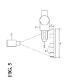
- the determinator 104A may detect a maximum height position of the workpieces W stored in the stocker 102 from the distance information acquired during the shape recognition of the workpieces W stored in the stocker 102. Then, the determinator 104A may determine a height position apart from the maximum height position by a predetermined distance as the destination of the workpiece W1. As shown in FIG. 5 , when the number of workpieces W stored in the stocker 102 reduces and thus the maximum height position of the stack of the workpieces W reduces, then in accordance with the reduced maximum height position, the destination position of the holding device 10 can be set at a lower height position h (where h ⁇ H).
- the workpiece W1 is positioned farther away from the camera 103. This reduces the area occupancy of the workpiece W1 in the image capture area R of the camera 103 (that is, the workpiece W1 looks smaller), as shown in FIG. 6 . As the workpiece W1 is transferred to the lower height position h, the held workpiece W1 becomes less likely to block the workpieces W stored in the stocker 102. This eliminates or minimizes the situation in which the workpiece W1 interferes with the camera 103 while the camera 103 is performing the shape recognition of the workpieces W.
- the determinator 104A may determine, as the destination of the workpiece W1, a position where the workpiece W1 does not block a candidate workpiece W2, as shown in FIG. 6 .
- the candidate workpiece W2 may include a single candidate workpiece W2 or a plurality of candidate workpieces W2. If the workpiece W1 held in this manner does not overlap at least the candidate workpiece W2 among the plurality of workpieces W stored in the stocker 102, the subsequent shape recognition and workpiece holding are facilitated. This saves the time for the workpiece handling work.
- the determinator 104A may not necessarily be built in the robot controller 104 but may be disposed separately from the robot controller 104.
- the camera 103 will not be limited to a three-dimensional camera; any other known two-dimensional cameras or three-dimensional sensors are possible insofar as the sensors are capable of performing shape recognition of the workpieces W in the stocker 102 and detecting the holding state of the workpiece W1 held by the robot 101.
- a two-dimensional camera it is possible to rotate the holding device 10 so as to enable the two-dimensional camera to detect the holding state of the workpiece W1 three-dimensionally (sterically).
- the holding device 10 may include, insofar as the holding device 10 is able to hold the workpiece W, a pair of fingers 10A, may include a finger swingable to grasp the workpiece W, or may use pneumatic or electromagnetic force to suck the workpiece W.
Landscapes
- Engineering & Computer Science (AREA)
- Mechanical Engineering (AREA)
- Robotics (AREA)
- Health & Medical Sciences (AREA)
- General Health & Medical Sciences (AREA)
- Orthopedic Medicine & Surgery (AREA)
- Manipulator (AREA)
Abstract
Description
- The present invention relates to a robot system and a method for producing a to-be-processed material.
- In recent years, various proposals have been made regarding bin picking technology, by which identically shaped workpieces, such as bolts, that are randomly stored (stacked in bulk) in a stocker are taken out of the stocker for handling. This technology includes shape recognition (three-dimensional recognition of position and posture) of the workpieces in the stocker, determination as to which workpiece to hold based on the recognition result, and taking the workpiece out of the stocker.
- In some situations of the bin picking, the workpieces overlap in the stocker in such a complicated manner that the to-be-held portion of the workpiece is hidden. For this and other reasons, it may not be possible to suitably hold the workpiece. As a result, the held workpiece may not be forwarded to the next step in a suitable holding state, leaving a possibility of degraded accuracy of workpiece handling work. In view of this, in addition to the use of a shape sensor for shape recognition of the workpieces in the stocker, it is necessary to detect whether the holding state of the held workpiece is suitable. (See Japanese Unexamined Patent Application Publication No.
2011-183537 - The contents of Japanese Unexamined Patent Application Publication No.
2011-183537 - Unfortunately, since the above-described conventional technique involves a holding-state detection device to detect the holding state in addition to the shape sensor, it is necessary to transfer the workpiece from the sensor area of the shape sensor to the holding-state detection device. The time necessary for the transfer has inhibited the attempt to shorten the time for workpiece handling work.
- The present disclosure has been made in view of the above-described circumstances, and it is an object of the present disclosure to provide a robot system and a method for producing a to-be-processed material that shorten the time for workpiece handling work.
- According to one aspect of the present disclosure, a
robot system 100 includes arobot 101, asensor 103, and acontroller 104. Therobot 101 includes aholder 10 configured to hold a first workpiece from among a plurality of workpieces stored in astocker 102. Thesensor 103 is configured to perform shape recognition of the plurality of workpieces stored in thestocker 102 and is configured to detect a holding state of the first workpiece held by therobot 101. Thecontroller 104 is configured to control thesensor 103 to perform the shape recognition of the plurality of workpieces stored in thestocker 102, configured to control therobot 101 to hold the first workpiece based on the shape recognition performed by thesensor 103 and to transfer the first workpiece to a particular position in a sensor area of thesensor 103, configured to control thesensor 103 to detect the holding state of the first workpiece held by therobot 101, and configured to control therobot 101 to place the first workpiece at a predetermined position or in a predetermined posture based on the holding state detected by thesensor 103. - According to another aspect of the present disclosure, a method for producing a to-be-processed material includes obtaining a to-be-processed material using a workpiece obtained using the above-described
robot system 100. - The present disclosure ensures a robot system and a method for producing a to-be-processed material that shorten the time for workpiece handling work.
- A more complete appreciation of the present disclosure and many of the attendant advantages thereof will be readily obtained as the same becomes better understood by reference to the following detailed description when considered in connection with the accompanying drawings, wherein:
-
FIG. 1 is a diagram schematically illustrating a configuration of a robot system according to an embodiment; -
FIG. 2 illustrates a state in which a workpiece is handled using the robot system shown inFIG. 1 ; -
FIG. 3 illustrates an image captured under the condition shown inFIG. 2 ; -
FIG. 4 illustrates another image captured under a condition different from the condition shown inFIG. 3 ; -
FIG. 5 illustrates a state in which a workpiece is handled using the robot system shown inFIG. 1 under a condition different from the condition shown inFIG. 2 ; and -
FIG. 6 illustrates an image captured under the condition shown inFIG. 5 . - The embodiments will now be described with reference to the accompanying drawings, wherein like reference numerals designate corresponding or identical elements throughout the various drawings.
- As shown in
FIG. 1 , arobot system 100 includes arobot 101, astocker 102, a camera (that is, sensor) 103, and a robot controller (that is, controller) 104. Therobot 101 grips (that is, holds) one workpiece W at a time from thestocker 102. - The
robot 101 is what is called an articulated robot. Therobot 101 includes a base fixed to a fixed surface, and anarm 101A having a plurality of rotary joints from the base to the distal end of thearm 101A. Thearm 101A is equipped with built-in servo motors. Each of the servo motors drives a corresponding joint. The joint is driven by therobot controller 104. - The
arm 101A of therobot 101 includes a holding device (that is, holder) 10 at the distal end of thearm 101A. Theholding device 10 includes a pair offinger members 10A. The pair offinger members 10A are openable and closable by an actuator that expands and diminishes the gap between the pair. Theholding device 10 is rotatable by an actuator about an axis oriented along the direction in which theholding device 10 is elongate. Therobot controller 104 controls the open-close operation of thefinger members 10A and the rotation of theholding device 10. - The
stocker 102 is a box made of metal, resin, or other material. In thestocker 102, the plurality of workpieces W are randomly disposed (stacked in bulk). While the workpieces W stacked in bulk in thestocker 102 are cubic inFIG. 1 , any other shapes are also possible (examples including a bolt shape, a bar shape, and a spherical shape). In some cases, some tens or hundreds of the workpieces W are put in multiple stacks. In this embodiment, however, only a few workpieces W in one or two stacks are shown for the convenience of description and illustration. - The
camera 103 is positioned over thestocker 102 and oriented vertically downward to capture an image of the inside of thestocker 102. Thecamera 103 is a three dimensional camera capable of capturing images (pixel arrangement data) from above thestocker 102 and acquiring distance information on an image. The height of thecamera 103 is adjusted to ensure that all the workpieces W stacked in thestocker 102 are within an image capture area (that is, field angle) R of thecamera 103. Thecamera 103 is fixed at this height position. Similarly to therobot 101, thecamera 103 is controlled by therobot controller 104. - The
camera 103 includes a built-in camera controller (not shown). The camera controller analyzes the image captured by thecamera 103. As described later, the analysis processing of the image includes shape recognition of the workpieces W stored in thestocker 102 and detection of a holding state of a workpiece W1 held by therobot 101. - As described above, the
robot controller 104 controls both therobot 101 and thecamera 103. - For example, the
robot controller 104 controls therobot 101 to transfer theholding device 10, which is at the distal end of therobot 101, to a desired position within a movable range of therobot 101, orient theholding device 10 in a desired direction, rotate theholding device 10, and open and close the pair offinger members 10A of theholding device 10. - Also, the
robot controller 104 controls thecamera 103 to acquire various pieces of information in addition to the above-described image and distance information from thecamera 103. The information that therobot controller 104 acquires from thecamera 103 includes a result of shape recognition of the workpieces W stored in thestocker 102 and a result of detection of the holding state of the workpiece W1 held by therobot 101. - A procedure of the handling work of the workpieces W (workpiece handling work) using the
robot system 100 will be described below. - First, the
robot controller 104 controls thecamera 103 to perform shape recognition of the workpieces W. Specifically, thecamera 103 captures an image of the workpieces W stored in thestocker 102, and performs shape recognition of the workpieces W stored in thestocker 102 based on the captured image. Then, thecamera 103 transmits a result of the shape recognition to therobot controller 104. - The shape recognition of the workpieces W includes, for example, detecting a shape, an orientation, and a height of the plurality of workpieces W stored in the
stocker 102 from the captured image and distance information; and, based on the detection result, selecting one or a plurality of candidates (candidate workpiece) to be held by therobot 101. In the case where a plurality of candidate workpieces are selected, it is possible to prioritize these candidates. - Next, the
robot controller 104 controls therobot 101 to hold the workpiece W selected through the shape recognition. Specifically, therobot controller 104 controls the holdingdevice 10 of therobot 101 to move to a position of the selected workpiece W. At the position, therobot controller 104 controls the pair offinger members 10A of the holdingdevice 10 to open and close itself so as to hold (grip) the selected workpiece W. - Next, as shown in
FIG. 2 , therobot controller 104 controls therobot 101 to transfer the workpiece W1 held by the holdingdevice 10 to a predetermined height position H in the image capture area of thecamera 103. After the transfer, therobot controller 104 controls thecamera 103 to detect the holding state of the workpiece W1 held by the holdingdevice 10. Specifically, as shown inFIG. 3 , thecamera 103 captures an image of the workpiece W1 positioned in the image capture area and detects the holding state of the workpiece W1 from the captured image. Then, thecamera 103 transmits a detection result of the holding state to therobot controller 104. That is, thecamera 103 and the image of the image capture area R used in the shape recognition of the workpieces W stored in thestocker 102 are also used in the detection of the holding state of the workpiece W1. - The detection of the holding state of the workpiece W1 is processing that includes detecting the state in which the workpiece W1 is being held by the holding
device 10 from an image and distance information obtained by imaging. Examples to be detected include position and posture (inclination angle) of the held workpiece W1. As necessary, it is possible to determine acceptability of the holding state of the workpiece W1 based on the detected position and/or posture. In this case, the determination result of acceptability is included in the detection result of the holding state of the workpiece W1 transmitted from thecamera 103 to therobot controller 104. - Then, the
robot controller 104 controls therobot 101 to subject the workpiece W1 held by the holdingdevice 10 to handling in the next step. - Examples of the handling in the next step include, but are not limited to, "step of placing the workpiece W1", "step of temporarily placing the workpiece W1 for re-recognition", and "step of excluding the workpiece W1".
- In the step of placing the workpiece W1, the
robot controller 104 controls therobot 101 to place the workpiece W1 onto a predetermined place other than in thestocker 102. Here, therobot controller 104 controls therobot 101 to correct (correct the position and/or correct the posture of) the workpiece W1 based on the holding state of the workpiece W1, and then to place the workpiece W1. - In the step of temporarily placing the workpiece W1 for re-recognition, the
robot controller 104 controls therobot 101 to place a workpiece W1 determined as unacceptable on a predetermined temporary table, not shown. On the predetermined temporary table, the workpiece W1 is subjected to shape recognition again and re-held by the holdingdevice 10. - In the step of excluding a workpiece W1 held (or re-held) by the holding
device 10 when the workpiece W1 is determined as unacceptable, therobot controller 104 controls therobot 101 to place the workpiece W1 on a predetermined exclusion area, so as to exclude the workpiece W1. - As has been described hereinbefore, the
robot system 100 includes therobot 101, thecamera 103, and therobot controller 104. Therobot 101 includes the holdingdevice 10 to hold a workpieces W from among the plurality of workpieces W stored in thestocker 102. Thecamera 103 performs shape recognition of the workpieces W stored in thestocker 102 and detects the holding state of the workpiece W1 held by therobot 101. Therobot controller 104 controls therobot 101 and thecamera 103. - Then, the
robot controller 104 controls thecamera 103 to perform shape recognition of the workpieces W stored in thestocker 102. Based on the shape recognition of the workpieces W recognized by thecamera 103, therobot controller 104 controls therobot 101 to hold one workpiece W from among the workpieces W. Then, therobot controller 104 controls therobot 101 to transfer the held workpiece W1 to a particular position H in the image capture area of thecamera 103, and controls thecamera 103 to detect the holding state of the workpiece W1. Based on the holding state detected by thecamera 103, therobot controller 104 controls therobot 101 to subject the workpiece W1 to handling in the next step. - In the
robot system 100, therobot controller 104 controls thecamera 103 to perform shape recognition of the workpieces W stored in thestocker 102 and detect the holding state of the workpiece W1 held by therobot 101. This requires no or minimal transfer between the place of shape recognition of the workpieces and the place of detection of the holding state of the workpiece. This, in turn, minimizes the time necessary for the transfer, if any. In contrast, the conventional art provides the shape sensor and the holding state detection device separately, and thus necessitates some time to transfer the workpiece from the place of shape recognition of the workpiece to the place of detection of the holding state of the workpiece. Therobot system 100 eliminates or minimizes the transfer time and thus saves the time for the workpiece handling work. - Similar advantageous effects are obtained in a method for producing a to-be-processed material when a workpiece W is obtained using the
robot system 100 and a to-be-processed material is obtained using the workpiece W. The to-be-processed material may be any article obtained using a workpiece W transferred or processed, such as in a combining operation, by the robot system 1. The to-be-processed material may be the workpiece W itself. Examples of the to-be-processed material include parts such as bolts and assembled structures such as automobiles. - As described above, the handling in the next step may be correcting the holding state of the held workpiece W1 and placing the workpiece W1. This ensures accurate placement of the workpiece W1 without re-holding of the workpiece W1 even when the workpiece W1 is not held in a suitable manner. This, in turn, saves time as compared with the case of re-holding the workpiece W1 when the workpiece W1 is not held in a suitable manner. The correction may be at least one of correction of the position of the workpiece W1 and correction of the posture of the workpiece W1.
- The
robot system 100 may include adeterminator 104A built in therobot controller 104. Thedeterminator 104A determines a destination position to which the held workpiece W1 is transferred. Thedeterminator 104A determines the destination position to which the workpiece W1 is to be transferred based on the image acquired during the shape recognition of the workpieces W stored in thestocker 102. - For example, the
determinator 104A detects an area in which no workpieces W exist from the image acquired during the shape recognition of the workpieces W in thestocker 102 to determine a position within the area as the destination of the workpiece W1. This ensures that the workpiece W1 is transferred to an area in which no workpieces W exist. Transferring the workpiece W1 to an area in which no workpieces W exist eliminates or minimizes overlap of the held workpiece W1 with the workpieces W stored in the stocker 102 (eliminates or minimizes the situation in which the workpieces W are hidden from the camera 103). Thus, the workpiece W1 is prevented from interfering with thecamera 103's shape recognition of the workpieces W. In therobot system 100, thedeterminator 104A may change the destination of the workpiece W1 with each cycle (that is, every time the holding state is confirmed). As a result, as shown inFIG. 4 , the workpiece W1 is transferred to another destination position different from the position shown inFIG. 3 . - Also, the
determinator 104A may detect a maximum height position of the workpieces W stored in thestocker 102 from the distance information acquired during the shape recognition of the workpieces W stored in thestocker 102. Then, thedeterminator 104A may determine a height position apart from the maximum height position by a predetermined distance as the destination of the workpiece W1. As shown inFIG. 5 , when the number of workpieces W stored in thestocker 102 reduces and thus the maximum height position of the stack of the workpieces W reduces, then in accordance with the reduced maximum height position, the destination position of the holdingdevice 10 can be set at a lower height position h (where h < H). Thus, when the height position of the holdingdevice 10 reduces, the workpiece W1 is positioned farther away from thecamera 103. This reduces the area occupancy of the workpiece W1 in the image capture area R of the camera 103 (that is, the workpiece W1 looks smaller), as shown inFIG. 6 . As the workpiece W1 is transferred to the lower height position h, the held workpiece W1 becomes less likely to block the workpieces W stored in thestocker 102. This eliminates or minimizes the situation in which the workpiece W1 interferes with thecamera 103 while thecamera 103 is performing the shape recognition of the workpieces W. - When a candidate workpiece next to be held is determined during the shape recognition of the workpieces W, the
determinator 104A may determine, as the destination of the workpiece W1, a position where the workpiece W1 does not block a candidate workpiece W2, as shown inFIG. 6 . The candidate workpiece W2 may include a single candidate workpiece W2 or a plurality of candidate workpieces W2. If the workpiece W1 held in this manner does not overlap at least the candidate workpiece W2 among the plurality of workpieces W stored in thestocker 102, the subsequent shape recognition and workpiece holding are facilitated. This saves the time for the workpiece handling work. - The
determinator 104A may not necessarily be built in therobot controller 104 but may be disposed separately from therobot controller 104. - Obviously, numerous modifications and variations of the present invention are possible in light of the above teachings. It is therefore to be understood that within the scope of the appended claims, the invention may be practiced otherwise than as specifically described herein.
- For example, the
camera 103 will not be limited to a three-dimensional camera; any other known two-dimensional cameras or three-dimensional sensors are possible insofar as the sensors are capable of performing shape recognition of the workpieces W in thestocker 102 and detecting the holding state of the workpiece W1 held by therobot 101. In the case of a two-dimensional camera, it is possible to rotate the holdingdevice 10 so as to enable the two-dimensional camera to detect the holding state of the workpiece W1 three-dimensionally (sterically). - The holding
device 10 may include, insofar as the holdingdevice 10 is able to hold the workpiece W, a pair offingers 10A, may include a finger swingable to grasp the workpiece W, or may use pneumatic or electromagnetic force to suck the workpiece W. - 10
- Holder
- 100
- Robot system
- 101
- Robot
- 102
- Stocker
- 103
- Sensor
- 104
- Robot controller
- 104A
- Determinator
- W, W1, W2
- Workpiece
Claims (6)
- A robot system (100), characterized by comprising:a robot (101) including a holder (10) configured to hold a first workpiece from among a plurality of workpieces stored in a stocker (102);a sensor (103) configured to perform shape recognition of the plurality of workpieces stored in the stocker (102) and configured to detect a holding state of the first workpiece held by the robot (101); anda controller (104) configured to control the sensor (103) to perform the shape recognition of the plurality of workpieces stored in the stocker (102), configured to control the robot (101) to hold the first workpiece based on the shape recognition performed by the sensor (103) and to transfer the first workpiece to a particular position in a sensor area of the sensor (103), configured to control the sensor (103) to detect the holding state of the first workpiece held by the robot (101), and configured to control the robot (101) to place the first workpiece at a predetermined position or in a predetermined posture based on the holding state detected by the sensor (103).
- The robot system (100) according to claim 1, wherein the controller (104) is configured to, as a handling operation, correct at least one of a position and a posture of the first workpiece and place the corrected first workpiece.
- The robot system (100) according to claim 1 or 2, further comprising a determinator (104A) configured to determine the particular position in the sensor area of the sensor (103) as a destination position of the first workpiece held and transferred by the robot (101).
- The robot system 100 according to claim 3, wherein the determinator (104A) is configured to determine the destination position as a position where the first workpiece held by the robot (101) does not overlap a candidate workpiece next to be held from the stocker (102).
- The robot system (100) according to claim 3, wherein the determinator (104A) is configured to determine the destination position in accordance with a maximum height position of the plurality of workpieces stored in the stocker (102).
- A method for producing a to-be-processed material, characterized by obtaining a to-be-processed material using a workpiece obtained using the robot system (100) according to any one of claims 1 to 5.
Applications Claiming Priority (1)
| Application Number | Priority Date | Filing Date | Title |
|---|---|---|---|
| JP2013052059A JP2014176923A (en) | 2013-03-14 | 2013-03-14 | Robot system and method for manufacturing workpiece |
Publications (2)
| Publication Number | Publication Date |
|---|---|
| EP2783810A2 true EP2783810A2 (en) | 2014-10-01 |
| EP2783810A3 EP2783810A3 (en) | 2015-09-23 |
Family
ID=50236052
Family Applications (1)
| Application Number | Title | Priority Date | Filing Date |
|---|---|---|---|
| EP14158332.8A Withdrawn EP2783810A3 (en) | 2013-03-14 | 2014-03-07 | Robot system and method for producing to-be-processed material |
Country Status (4)
| Country | Link |
|---|---|
| US (1) | US20140277694A1 (en) |
| EP (1) | EP2783810A3 (en) |
| JP (1) | JP2014176923A (en) |
| CN (1) | CN104044132A (en) |
Cited By (3)
| Publication number | Priority date | Publication date | Assignee | Title |
|---|---|---|---|---|
| AT519452B1 (en) * | 2017-01-18 | 2018-07-15 | Tgw Logistics Group Gmbh | Method and device for picking goods |
| US10589422B2 (en) | 2017-01-11 | 2020-03-17 | Fanuc Corporation | Article conveying apparatus |
| DE102019208187B4 (en) | 2018-06-08 | 2022-05-19 | Fanuc Corporation | Robot system and control method for a robot system |
Families Citing this family (27)
| Publication number | Priority date | Publication date | Assignee | Title |
|---|---|---|---|---|
| JP6140204B2 (en) | 2015-02-06 | 2017-05-31 | ファナック株式会社 | Transport robot system with 3D sensor |
| CN105159241A (en) * | 2015-07-23 | 2015-12-16 | 龙工(上海)叉车有限公司 | Internal combustion balance weight fork truck positioning management system |
| CN106041942B (en) * | 2016-07-01 | 2018-09-25 | 江苏捷帝机器人股份有限公司 | A kind of crawl size mixes the manipulator of pipe |
| CN109791614B (en) * | 2016-07-15 | 2023-08-18 | 麦格纳国际公司 | System and method for adaptive case picking for manufacturing |
| US10078908B2 (en) * | 2016-08-12 | 2018-09-18 | Elite Robotics | Determination of relative positions |
| JP6614075B2 (en) | 2016-09-07 | 2019-12-04 | 株式会社ダイフク | Material loading equipment |
| DK3537867T3 (en) * | 2016-11-08 | 2023-11-06 | Dogtooth Tech Limited | ROBOT FRUIT PICKING SYSTEM |
| JP2018136896A (en) * | 2017-02-24 | 2018-08-30 | キヤノン株式会社 | Information processing apparatus, system, information processing method, and article manufacturing method |
| KR101963643B1 (en) * | 2017-03-13 | 2019-04-01 | 한국과학기술연구원 | 3D Image Generating Method And System For A Plant Phenotype Analysis |
| JP6923383B2 (en) * | 2017-07-27 | 2021-08-18 | 株式会社日立物流 | Picking robot and picking system |
| CN108698224A (en) * | 2017-08-23 | 2018-10-23 | 深圳蓝胖子机器人有限公司 | The method of robot store items, the system and robot of control robot store items |
| CN108160530A (en) * | 2017-12-29 | 2018-06-15 | 苏州德创测控科技有限公司 | A kind of material loading platform and workpiece feeding method |
| CN110196568B (en) * | 2018-02-26 | 2022-06-24 | 宝山钢铁股份有限公司 | Method for grabbing plate blank by travelling crane |
| JP6795007B2 (en) * | 2018-04-27 | 2020-12-02 | 株式会社ダイフク | Picking equipment |
| JP7233858B2 (en) | 2018-06-13 | 2023-03-07 | オムロン株式会社 | ROBOT CONTROL DEVICE, ROBOT CONTROL METHOD, AND ROBOT CONTROL PROGRAM |
| CN110228068A (en) * | 2019-06-14 | 2019-09-13 | 广西科技大学 | A kind of robot plane setting quick positioning system and its method for rapidly positioning |
| WO2021014563A1 (en) * | 2019-07-23 | 2021-01-28 | 株式会社Fuji | Component supply device and automatic assembly system |
| US11648674B2 (en) * | 2019-07-23 | 2023-05-16 | Teradyne, Inc. | System and method for robotic bin picking using advanced scanning techniques |
| US11679508B2 (en) * | 2019-08-01 | 2023-06-20 | Fanuc Corporation | Robot device controller for controlling position of robot |
| JP7356867B2 (en) * | 2019-10-31 | 2023-10-05 | ミネベアミツミ株式会社 | gripping device |
| CN110817228A (en) * | 2019-12-11 | 2020-02-21 | 南京邮电大学 | Unmanned storage carrier |
| JP7517176B2 (en) * | 2021-01-28 | 2024-07-17 | トヨタ自動車株式会社 | Task System |
| JP7673601B2 (en) | 2021-09-13 | 2025-05-09 | トヨタ自動車株式会社 | Workpiece holding device, workpiece holding method, program, and control device |
| CN114979473A (en) * | 2022-05-16 | 2022-08-30 | 遥相科技发展(北京)有限公司 | Industrial robot control method |
| WO2023233557A1 (en) * | 2022-05-31 | 2023-12-07 | 日本電気株式会社 | Robot system, control method, and recording medium |
| US12433259B2 (en) * | 2023-01-13 | 2025-10-07 | Beekeeping 101 Llc | Automated system and method for application of a beehive treatment |
| CN120166193A (en) | 2023-07-06 | 2025-06-17 | 浙江恒逸石化有限公司 | A channel monitoring method, device, equipment and storage medium |
Citations (1)
| Publication number | Priority date | Publication date | Assignee | Title |
|---|---|---|---|---|
| JP2011183537A (en) | 2010-03-11 | 2011-09-22 | Yaskawa Electric Corp | Robot system, robot device and work taking-out method |
Family Cites Families (10)
| Publication number | Priority date | Publication date | Assignee | Title |
|---|---|---|---|---|
| US4402053A (en) * | 1980-09-25 | 1983-08-30 | Board Of Regents For Education For The State Of Rhode Island | Estimating workpiece pose using the feature points method |
| JP4174342B2 (en) * | 2003-02-19 | 2008-10-29 | ファナック株式会社 | Work transfer device |
| JP3876260B2 (en) * | 2004-09-16 | 2007-01-31 | ファナック株式会社 | Article supply equipment |
| CA2744333C (en) * | 2008-11-21 | 2015-11-03 | Dematic Corp. | Stacking apparatus and method of multi-layer stacking of objects on a support |
| JP5333344B2 (en) * | 2009-06-19 | 2013-11-06 | 株式会社安川電機 | Shape detection apparatus and robot system |
| EP2470333A2 (en) * | 2009-08-27 | 2012-07-04 | ABB Research Ltd. | Robotic picking of parts from a parts holding bin |
| JP5528095B2 (en) * | 2009-12-22 | 2014-06-25 | キヤノン株式会社 | Robot system, control apparatus and method thereof |
| JP5423441B2 (en) * | 2010-02-03 | 2014-02-19 | 株式会社安川電機 | Work system, robot apparatus, and manufacturing method of machine product |
| JP5382621B2 (en) * | 2010-06-03 | 2014-01-08 | 株式会社安川電機 | Transfer equipment |
| JP5685027B2 (en) * | 2010-09-07 | 2015-03-18 | キヤノン株式会社 | Information processing apparatus, object gripping system, robot system, information processing method, object gripping method, and program |
-
2013
- 2013-03-14 JP JP2013052059A patent/JP2014176923A/en active Pending
-
2014
- 2014-01-16 CN CN201410020324.1A patent/CN104044132A/en active Pending
- 2014-03-07 EP EP14158332.8A patent/EP2783810A3/en not_active Withdrawn
- 2014-03-13 US US14/210,348 patent/US20140277694A1/en not_active Abandoned
Patent Citations (1)
| Publication number | Priority date | Publication date | Assignee | Title |
|---|---|---|---|---|
| JP2011183537A (en) | 2010-03-11 | 2011-09-22 | Yaskawa Electric Corp | Robot system, robot device and work taking-out method |
Cited By (5)
| Publication number | Priority date | Publication date | Assignee | Title |
|---|---|---|---|---|
| US10589422B2 (en) | 2017-01-11 | 2020-03-17 | Fanuc Corporation | Article conveying apparatus |
| AT519452B1 (en) * | 2017-01-18 | 2018-07-15 | Tgw Logistics Group Gmbh | Method and device for picking goods |
| AT519452A4 (en) * | 2017-01-18 | 2018-07-15 | Tgw Logistics Group Gmbh | Method and device for picking goods |
| US11559899B2 (en) | 2017-01-18 | 2023-01-24 | Tgw Logistics Group Gmbh | Method and device for picking goods |
| DE102019208187B4 (en) | 2018-06-08 | 2022-05-19 | Fanuc Corporation | Robot system and control method for a robot system |
Also Published As
| Publication number | Publication date |
|---|---|
| CN104044132A (en) | 2014-09-17 |
| EP2783810A3 (en) | 2015-09-23 |
| US20140277694A1 (en) | 2014-09-18 |
| JP2014176923A (en) | 2014-09-25 |
Similar Documents
| Publication | Publication Date | Title |
|---|---|---|
| US20140277694A1 (en) | Robot system and method for producing to-be-processed material | |
| US20140277734A1 (en) | Robot system and a method for producing a to-be-processed material | |
| CN109955222B (en) | Article transfer device, robot system, and article transfer method | |
| CN110497401B (en) | Robot system for taking out bulk work and control method of robot system | |
| JP4226623B2 (en) | Work picking device | |
| JP5266377B2 (en) | Taking-out device having a function of correcting the posture of an article | |
| JP6088563B2 (en) | Work picking robot system having position and orientation conversion operation function, and work picking method | |
| US9205563B2 (en) | Workpiece takeout system, robot apparatus, and method for producing a to-be-processed material | |
| US9102063B2 (en) | Robot apparatus | |
| JP6741222B2 (en) | Robot work transfer method and work transfer device | |
| US10434652B2 (en) | Workpiece picking system | |
| US10596707B2 (en) | Article transfer device | |
| EP2921267A2 (en) | Robot system, calibration method in robot system, and position correcting method in robot system | |
| US11213954B2 (en) | Workpiece identification method | |
| CN107150032A (en) | A kind of workpiece identification based on many image acquisition equipments and sorting equipment and method | |
| CN109791614A (en) | The system and method that adaptability chest for manufacturing industry picks up | |
| JP2010131685A (en) | Robot system and imaging method | |
| US20240269853A1 (en) | Calibration method, calibration device, and robotic system | |
| JP2016185573A (en) | A robot system having a function of correcting the take-out path of an object | |
| JP2015182212A (en) | Robot system, robot, control device, and control method | |
| CN204868885U (en) | A robot system for controlling work piece | |
| JP2011177863A (en) | Gripping device | |
| JP7436170B2 (en) | robot system | |
| CN109551458B (en) | Robot system | |
| JP6708142B2 (en) | Robot controller |
Legal Events
| Date | Code | Title | Description |
|---|---|---|---|
| 17P | Request for examination filed |
Effective date: 20140307 |
|
| AK | Designated contracting states |
Kind code of ref document: A2 Designated state(s): AL AT BE BG CH CY CZ DE DK EE ES FI FR GB GR HR HU IE IS IT LI LT LU LV MC MK MT NL NO PL PT RO RS SE SI SK SM TR |
|
| AX | Request for extension of the european patent |
Extension state: BA ME |
|
| PUAI | Public reference made under article 153(3) epc to a published international application that has entered the european phase |
Free format text: ORIGINAL CODE: 0009012 |
|
| PUAL | Search report despatched |
Free format text: ORIGINAL CODE: 0009013 |
|
| AK | Designated contracting states |
Kind code of ref document: A3 Designated state(s): AL AT BE BG CH CY CZ DE DK EE ES FI FR GB GR HR HU IE IS IT LI LT LU LV MC MK MT NL NO PL PT RO RS SE SI SK SM TR |
|
| AX | Request for extension of the european patent |
Extension state: BA ME |
|
| RIC1 | Information provided on ipc code assigned before grant |
Ipc: B25J 9/16 20060101AFI20150820BHEP |
|
| STAA | Information on the status of an ep patent application or granted ep patent |
Free format text: STATUS: THE APPLICATION IS DEEMED TO BE WITHDRAWN |
|
| 18D | Application deemed to be withdrawn |
Effective date: 20160324 |