EP2783800A2 - Robot system and method for controlling robot system - Google Patents
Robot system and method for controlling robot system Download PDFInfo
- Publication number
- EP2783800A2 EP2783800A2 EP14157180.2A EP14157180A EP2783800A2 EP 2783800 A2 EP2783800 A2 EP 2783800A2 EP 14157180 A EP14157180 A EP 14157180A EP 2783800 A2 EP2783800 A2 EP 2783800A2
- Authority
- EP
- European Patent Office
- Prior art keywords
- robot
- region
- operation load
- moving body
- actuator
- Prior art date
- Legal status (The legal status is an assumption and is not a legal conclusion. Google has not performed a legal analysis and makes no representation as to the accuracy of the status listed.)
- Granted
Links
Images




Classifications
-
- B—PERFORMING OPERATIONS; TRANSPORTING
- B25—HAND TOOLS; PORTABLE POWER-DRIVEN TOOLS; MANIPULATORS
- B25J—MANIPULATORS; CHAMBERS PROVIDED WITH MANIPULATION DEVICES
- B25J9/00—Program-controlled manipulators
- B25J9/16—Program controls
- B25J9/1674—Program controls characterised by safety, monitoring, diagnostic
- B25J9/1676—Avoiding collision or forbidden zones
-
- B—PERFORMING OPERATIONS; TRANSPORTING
- B25—HAND TOOLS; PORTABLE POWER-DRIVEN TOOLS; MANIPULATORS
- B25J—MANIPULATORS; CHAMBERS PROVIDED WITH MANIPULATION DEVICES
- B25J9/00—Program-controlled manipulators
- B25J9/16—Program controls
- B25J9/1674—Program controls characterised by safety, monitoring, diagnostic
-
- G—PHYSICS
- G05—CONTROLLING; REGULATING
- G05B—CONTROL OR REGULATING SYSTEMS IN GENERAL; FUNCTIONAL ELEMENTS OF SUCH SYSTEMS; MONITORING OR TESTING ARRANGEMENTS FOR SUCH SYSTEMS OR ELEMENTS
- G05B19/00—Program-control systems
- G05B19/02—Program-control systems electric
- G05B19/18—Numerical control [NC], i.e. automatically operating machines, in particular machine tools, e.g. in a manufacturing environment, so as to execute positioning, movement or co-ordinated operations by means of program data in numerical form
- G05B19/406—Numerical control [NC], i.e. automatically operating machines, in particular machine tools, e.g. in a manufacturing environment, so as to execute positioning, movement or co-ordinated operations by means of program data in numerical form characterised by monitoring or safety
- G05B19/4061—Avoiding collision or forbidden zones
-
- G—PHYSICS
- G05—CONTROLLING; REGULATING
- G05B—CONTROL OR REGULATING SYSTEMS IN GENERAL; FUNCTIONAL ELEMENTS OF SUCH SYSTEMS; MONITORING OR TESTING ARRANGEMENTS FOR SUCH SYSTEMS OR ELEMENTS
- G05B2219/00—Program-control systems
- G05B2219/30—Nc systems
- G05B2219/40—Robotics, robotics mapping to robotics vision
- G05B2219/40202—Human robot coexistence
-
- G—PHYSICS
- G05—CONTROLLING; REGULATING
- G05B—CONTROL OR REGULATING SYSTEMS IN GENERAL; FUNCTIONAL ELEMENTS OF SUCH SYSTEMS; MONITORING OR TESTING ARRANGEMENTS FOR SUCH SYSTEMS OR ELEMENTS
- G05B2219/00—Program-control systems
- G05B2219/30—Nc systems
- G05B2219/40—Robotics, robotics mapping to robotics vision
- G05B2219/40203—Detect position of operator, create non material barrier to protect operator
Definitions
- the present disclosure relates to a robot system and a method for controlling the robot system.
- a robot with an operable working arm has been suggested.
- a safety fence is disposed around the working arm to separate an operation region for the working arm separated from an operation region for people.
- a person may enter the safety fence to supply the work object.
- both the robot and the people have expanded opportunities to work together in a space where the operation regions for the working arm and the people are not separated.
- the use of the robot in such a circumstance may cause a risk that the robot and a person interfere with each other if the person enters the operation region for the working arm.
- a safety countermeasure has been built for avoiding such a risk.
- a man ⁇ machine working system disclosed in Japanese Patent No. 4219870 includes a transmitter provided for a person, a receiver attached to a device to respond to the transmitter, and a position detector. The position detector detects the position of the person relative to the device by calculating an output signal from the receiver.
- the positional relation of the person to the device is detected by the position detector. Based on the positional relation, the operation region for people is set.
- a robot system includes a human detection device for detecting the presence of a human within an operation region for an industrial robot.
- the robot system according to JP-A-2010-167523 includes an electric supply adjusting device for adjusting the amount of current to be supplied to a robot control device.
- the electric supply adjusting device changes the amount of current in response to a signal output from the human detection device.
- the operation load of the robot body or the operation load of the working arm is, however, not always constant and changes during the operation of the robot body.
- the influence (risk) on the people from the device is changed depending on the operation load of the robot body or the operation load of the working arm. Therefore, setting the operation region for people depending on merely the positional relation relative to the device may not be the sufficient safety countermeasure.
- the safety countermeasure becomes excessive for some operation loads of the robot body; in those cases, the working efficiency of the robot body may deteriorate.
- An object of the present disclosure is to provide a robot system with higher safety, and a method for controlling the robot system.
- a robot system of the present disclosure includes: a robot including an operable working arm driven by an actuator; an operation load detection unit configured to detect an operation load of the actuator; a region setting unit that sets a region with a predetermined range around the robot; a moving body detection unit configured to detect a position of a moving body other than the robot; and an abnormality determination unit that determines abnormality when detecting of the position of the moving body within the region, wherein the region setting unit changes the range of the region in accordance with the operation load of the actuator.
- a robot system of an exemplary aspect of the present disclosure includes: a robot including an operable working arm driven by an actuator; an operation load detection unit configured to detect an operation load of the actuator; a region setting unit that sets a region with a predetermined range around the robot; a moving body detection unit configured to detect a position of a moving body other than the robot; and an abnormality determination unit that determines abnormality when detecting of the position of the moving body within the region, wherein the region setting unit changes the range of the region in accordance with the operation load of the actuator.
- the robot may have a base that supports the working arm and a moving mechanism configured to move the base.
- a process of the abnormality determination by the abnormality determination unit may include at least one control of motion of operation of the robot, issuing of alarm, reduction of motion speed of the robot, and reduction of operation load of the actuator.
- the robot may execute a plurality of works by having a motion program installed therein.
- the motion program may contain information that defines the motion speed of the robot.
- the robot may execute a plurality of works by having a motion program installed therein.
- the abnormality determination unit may perform different abnormality determination in accordance with the work of the robot in execution when detecting the position of the moving body within the region.
- the operation load detection unit may detect at least one component of an X-direction component, a Y-direction component, and a Z-direction component on an XYZ coordinate system of the operation load at an end of the working arm. Further, the region setting unit may set the range of the region in accordance with at least one component among the X-direction component, the Y-direction component, and the Z-direction component of the load detected by the operation load detection unit.
- the moving body detection unit may be a laser ranging device, a photographing device, or a data receiving device.
- the data receiving device is configured to read data from an IC tag provided for the moving body.
- the region setting unit may set a plurality of different regions around the robot.
- the abnormality determination unit may perform different abnormality determination for each of the regions.
- the abnormality determination unit may cancel the abnormality determination when detecting that the position of the moving body is not within the region after the abnormality determination.
- the operation load detection unit may detect the operation load by estimating the operation load based on at least one of a driving current value of the actuator and posture data for the robot. Further, the operation load detection unit may detect the operation load by estimating the operation load based on content of a motion order input to the robot.
- a method for controlling a robot system of another exemplary aspect of the present disclosure includes: detecting an operation load of an actuator of a robot having a working arm driven by the actuator; setting a region with a predetermined range around the robot; detecting a position of a moving body other than the robot; and determining abnormality when detecting of the position of the moving body within the region, wherein the setting of the region includes changing the range of the region in accordance with the operation load of the actuator.
- the robot system and the method for controlling the robot system according to the present disclosure further improve the safety of the robot system.
- FIG. 1 is a schematic diagram illustrating an operation of the robot system according to the first embodiment.
- FIG. 2 is a schematic diagram illustrating an example in which operation load of an actuator is greater than that in the state illustrated in FIG. 1 .
- FIG. 3 is a schematic diagram illustrating an example in which operation load of the actuator is less than that in the state illustrated in FIG. 1 .
- FIG. 1 illustrates a state in which a hand at an end of a working arm 4 holds an article 12a.
- FIG. 2 illustrates a state in which the hand at the end of the working arm 4 holds an article 12b, which is larger than the article 12a illustrated in FIG. 1 .
- FIG. 3 illustrates the state in which the hand at the end of the working arm 4 holds nothing.
- the operation load of the actuator 11 is greater than that in the state illustrated in FIG. 1 .
- the operation load of the actuator 11 is less than that in the state illustrated in FIG. 1 .
- the operation load of the actuator 11 variously changes in this manner when the hand at the end of the working arm 4 holds different products depending on the work of the working arm 4.
- FIG. 1 , FIG. 2 , and FIG. 3 depict examples for describing the magnitude of the operation load of the actuator 11.
- the operation load of the actuator 11 changes not just by the holding of the article 12a as illustrated in FIG. 1 .
- a robot system 2 includes a robot 3, an operation load detection unit 5, a region setting unit 6, a moving body detection unit 7, an abnormality determination unit 8, and a motion control unit 13.
- the robot 3 has the working arm 4 driven by the actuator 11.
- the working arm 4 is driven by the actuator 11 to execute the operation such as expansion, contraction, stretch, or rotation.
- the robot 3 includes one or more working arms 4.
- the operation load detection unit 5 detects the operation load of the actuator 11.
- the operation load of the actuator 11 refers to the load consuming the energy generated by the actuator 11.
- the operation load of the actuator 11 corresponds to, for example, static load, resistance load, or inertial load.
- the static load refers to a force required for the hand at the end of the working arm 4 to hold the article 12a.
- the resistance load refers to a force for driving the working arm 4 or keeping the posture of the working arm 4.
- the inertial load refers to a force that resists the inertia generated due to the acceleration or deceleration for driving the working arm 4.
- the region setting unit 6 sets a region 10 with a predetermined range around the robot 3.
- the region 10 may be a circular region with a predetermined radius in which the working arm 4 serves as a center.
- the moving body detection unit 7 detects the position of a moving body 9 other than the robot 3.
- the moving body 9 other than the robot 3 corresponds to, for example, a person, a hand lift, a conveyer truck, or a self-running robot other than the robot 3.
- the moving body 9 may be a person or a human-powered traveling body.
- the abnormality determination unit 8 determines the abnormality when detecting of the position of the moving body 9 within the region 10.
- the motion control unit 13 controls the motion of the robot 3 or the working arm 4. In accordance with the motion program to be described later, the motion control unit 13 outputs the motion order to the actuator 11 of the working arm 4. On the other hand, the motion control unit 13 monitors the positional information or the like of the actuator 11 and controls the working arm 4 so that the working arm 4 operates based on the motion order. The motion control unit 13 changes the motion speed of the working arm 4 or stops the working arm 4 on the basis of the abnormality determination made by the abnormality determination unit 8.
- the robot system 2 includes a storage unit (not shown) for storing the motion program or the parameters necessary for the control.
- the region setting unit 6 changes the range of the region 10 in accordance with the operation load of the actuator 11.
- the range of the region 10 where the abnormality determination is performed is wide as a region 10a illustrated in FIG. 2 .
- the range of the region 10 where the abnormality determination is performed is narrow as a region 10b illustrated in FIG. 3 .
- the robot system 2 can variably set the region 10 where the abnormality is determined upon the entry of the moving body 9.
- the moving body 9 can secure the minimum safety distance in accordance with the work of the robot 3. This reduces the space occupied by the robot 3. If the moving body 9 is absent in the region 10, the robot 3 can operate without the abnormality determination. As a result, deterioration in productivity and rate of operation of the robot 3 can be suppressed.
- the robot system 2 illustrated in FIG. 1 includes, for example, the robot 3 having the multi-joint working arm 4, which is disposed on a floor, a ceiling, a wall surface, or the like.
- the robot 3 is not limited to the robot 3 described above as long as the robot has the working arm 4 driven by the actuator 11.
- the robot 3 may have a base that supports the working arm 4 and a moving mechanism that moves this base.
- the operation load detection unit 5 is disposed in the robot 3.
- the operation load detection unit 5 for example, a sensor for converting the load or force into an electric signal, such as a load cell, is given.
- the operation load detection unit 5 may be a device configured to detect the operation load by estimating the operation load based on at least one of the driving current value of the actuator 11 and the posture data for the robot 3.
- the operation load detection unit 5 may include a driving current value measurement unit, a load data storage unit, and an operation load estimation and detection unit (all of which are not shown).
- the driving current value measurement unit measures the driving current value of the actuator 11.
- the load data storage unit stores the load current value characteristic of the actuator 11 in advance.
- the operation load estimation and detection unit estimates and detects the operation load of the actuator 11 based on the load current value characteristic and the driving current value.
- the operation load estimation and detection unit reads out the load current value characteristic from the load data storage unit. Then, by comparing the load current value characteristic and the driving current value measured by the driving current value measurement unit, the operation load estimation and detection unit estimates and detects the operation load of the current actuator 11.
- the operation load detection unit 5 may be configured to detect the operation load of the actuator 11 not directly but indirectly.
- the moving body detection unit 7 detects the position of the moving body 9 other than the robot 3 around the robot 3. If the moving body 9 as the detection target is the one moving on the floor, the moving body detection unit 7 such as a laser ranging device may be disposed at a predetermined height from the floor as illustrated in FIG. 1 to detect the position of the moving body 9 at the predetermined height.
- the moving body detection unit 7 is not limited to the laser ranging device.
- the moving body detection unit 7 may be, for example, a photographing device or a data receiving device for reading data from an IC tag provided for the moving body 9.
- the region setting unit 6 may have a storage unit for storing correlation data.
- the correlation data are obtained by associating the operation load of the actuator 11 and the range of the region 10 in advance.
- the region setting unit 6 reads out the correlation data from such a storage unit.
- the region setting unit 6 can set the range of the region 10 that is suitable for the operation load detected by the operation load detection unit 5 on the basis of the correlation data.
- the abnormality determination unit 8 determines whether the state is abnormal or not based on the range of the region 10 set by the region setting unit 6 and the position of the moving body 9 detected by the moving body detection unit 7. In other words, the state is determined as being abnormal when detecting of the position of the moving body 9 within the region 10. For example, the state is determined as being abnormal if an appropriate distance is not secured between the moving body 9 and the robot 3.
- the motion control unit 13 performs a predetermined process. This predetermined process may include at least one control of the stop of motion of the robot 3, the issuing of alarm, the reduction of speed of the robot 3, and the reduction of operation load of the actuator 11.
- the motion control unit 13 may issue an alarm. This can warn the moving body 9 or another worker around the moving body 9 that the moving body 9 is too close to the robot 3. This can suppress the interference between the moving body 9 and the robot 3. Even though the moving body 9 interferes with the robot 3, the influence of the interference on the moving body 9 can be reduced by reducing the motion speed of the robot 3. When the motion speed of the robot 3 is reduced, the moving body 9 can be easily retracted. By reducing the operation load of the actuator 11, the influence from the interference between the moving body 9 and the working arm 4 can be reduced.
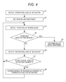
- FIG. 4 is a flowchart illustrating the procedure for changing the range of the region 10 and determining the abnormality according to the robot system 2 of the first embodiment.
- the operation load detection unit 5 detects the operation load of the actuator 11 in Step S 1.
- the detection of the operation load of the actuator 11 is to set the region 10 initially around the robot 3.
- the operation load detection unit 5 may be, for example, a sensor such as a load cell.
- the operation load detection unit 5 may detect the operation load by estimating the operation load based on at least one of the driving current value of the actuator 11 and the posture data for the robot 3.
- Step S2 the region setting unit 6 sets the region 10 around the robot 3 based on the detected operation load of the actuator 11. If there is any change in the operation load of the actuator 11, this region 10 varies depending on the operation load of the actuator 11 as appropriate in Step S7 and Step S8 to be described later. If the operation load of the actuator 11 is large, the range of the region 10 is set wider. Meanwhile, if the operation load of the actuator 11 is small, the range of the region 10 is set narrower.
- the region setting unit 6 may include a storage unit storing the correlation data in which the operation load of the actuator 11 and the range of the region 10 are associated with each other. In this case, the region setting unit 6 may set the range of the region 10 as below. First, the region setting unit 6 reads out the correlation data from the storage unit. Then, the region setting unit 6 sets the range of the region 10 to match the operation load detected by the operation load detection unit 5.
- the moving body detection unit 7 detects the position of the moving body 9.
- the moving body detection unit 7 may be, for example, a laser ranging device, a photographing device, or a data receiving device for reading data from an IC tag provided for the moving body 9.
- Step S4 the abnormality determination unit 8 determines whether the position of the moving body 9 is within the region 10 or not. If the position of the moving body 9 is within the region 10, the process advances to Step S5 where the state is determined as being abnormal. In other words, if the position of the moving body 9 is within the region 10, the state is determined as being abnormal because the moving body 9 does not secure enough distance relative to the operation load of the actuator 11. If the state is determined as being abnormal, an appropriate instruction may be given to at least one of the robot 3 and the moving body 9. This secures the safety of the robot 3 and the moving body 9. If the position of the moving body 9 is not within the region 10, the state is not determined as being abnormal. On this point, the motion of the robot 3 and the work of the moving body 9 are not restricted.
- Step S6 the operation load of the actuator 11 is detected again.
- the operation load of the actuator 11 is not always constant, and may vary during the work of the robot 3. Therefore, if the state is not determined as being abnormal in Step S4, the operation load detection unit 5 detects the operation load of the actuator 11 again.
- Step S7 the region setting unit 6 checks if there is a change in the operation load of the actuator 11. If there is a change in the operation load of the actuator 11, the process proceeds to Step S8 where the region setting unit 6 changes the range of the region 10 in accordance with the operation load of the actuator 11.
- the operation load detection unit 5 may detect the operation load of the actuator 11 continuously.
- the region setting unit 6 may change the range of the region 10 in accordance with the operation load of the actuator 11 in real time. That is, for the convenience of the description, the operation load of the actuator 11 is detected again in Step S6 after the detection of the position of the moving body 9 in Step S3 and the determination on whether the position of the moving body 9 is within the region 10 in Step S4. However, the operation load of the actuator 11 may be detected continuously in parallel to the detection of the position of the moving body 9 in Step S3 and the determination on whether the position of the moving body 9 is within the region 10 in Step S4. Then, the range of the region 10 may be changed as appropriate in accordance with the change in operation load of the actuator 11.
- Step S7 If there is no change in the operation load of the actuator 11 in Step S7, the process returns to Step S3 where the moving body detection unit 7 detects the position of the moving body 9 again. In other words, even though the state is not determined as being abnormal in Step S4, the further movement of the moving body 9 would change the position. Thus, even though there is no change in the operation load in Step S7, the moving body detection unit 7 detects the position of the moving body 9 again. Moreover, even in the case where the range of the region 10 is changed in Step S8, the process returns to Step S3 similarly and the moving body detection unit 7 detects the position of the moving body 9 again.
- the abnormality determination unit 8 determines again whether the position of the moving body 9 is within the region 10 or not in Step S4. Further, in a manner similar to the detection of the operation load of the actuator 11, the moving body detection unit 7 may continuously detect the position of the moving body 9. In other words, the abnormality determination unit 8 may determine whether the real-time position of the moving body 9 is within the region 10 changed according to the real-time operation load of the actuator 11 by knowing the real-time position of the moving body 9.
- the operation region for people has been uniformly set according to the positional relation relative to the robot. Therefore, the influence (risk) depending on the operation load of the actuator 11 has not been taken into consideration in the known robot system.
- the range of the region 10 can be changed according to the operation load of the actuator 11. Therefore, even though the moving body 9 is always present at the same position, for example, the state may be determined as being abnormal if the enough safety distance is no longer secured relative to the operation load of the actuator 11. Therefore, the moving body 9 can secure the minimum safety distance according to the work of the robot 3. This can reduce the space occupied by the robot 3.
- the robot 3 can operate at the original speed. Since this can shorten the takt time, the productivity and rate of operation of the robot 3 can be improved.
- FIG. 5 is a schematic diagram illustrating the operation of a robot system according to a first modified example.
- a robot system 2a includes the robot 3, the operation load detection unit 5, the region setting unit 6, a moving body detection unit 7a, the abnormality determination unit 8, and the motion control unit 13.
- the moving body detection unit 7a of the robot system 2a includes a plurality of moving body sensing sensors disposed on a ceiling around the robot 3. These moving body sensing sensors are disposed at predetermined intervals at different positions whose distance from the robot 3 is different. In the robot system 2a, the position of the moving body 9 other than the robot 3 can be detected using such plural moving body sensing sensors. In the example illustrated in FIG.
- the three moving body sensing sensors are disposed at almost equal intervals on the ceiling around the robot 3.
- the moving body sensing sensor may be, for example, a known sensor using an infrared ray, an ultrasonic wave, visible light, or the like. Since the other configurations of the robot system 2a of the first modified example are similar to those of the first embodiment, the description is omitted.
- FIG. 6 is a flowchart illustrating the procedure for changing the range of the region 10 and the procedure for the abnormality determination of the robot system 2 or 2a according to a second modified example.
- the operation load detection unit 5 first detects the operation load of the actuator 11 (or the working arm 4) in Step S9.
- the region setting unit 6 sets the region 10 around the robot 3 on the basis of the detected operation load of the actuator 11.
- the moving body detection unit 7 or 7a detects the position of the moving body 9.
- the abnormality determination unit 8 determines whether the position of the moving body 9 is within the region 10 or not.
- Step S16 the state is determined as being abnormal.
- the moving body detection unit 7 or 7a detects the position of the moving body 9 again in Step S17.
- the abnormality determination unit 8 determines whether the po sition of the moving body 9 is within the region 10 or not. Then, if the position of the moving body 9 is detected within the region 10, the process returns to Step S16 and the abnormality determination is maintained. If the position of the moving body 9 is not within the region 10, the process advances to Step S19 where the abnormality determination is cancelled.
- the motion control unit 13 may reset the robot 3 so that the robot 3 operates at the motion speed immediately before the abnormality determination.
- Step S 13 the operation load of the actuator 11 is detected again.
- Step S 14 whether there is a change in operation load of the actuator 11 is determined. If there is a change in operation load of the actuator 11, the process advances to Step S15 where the range of the region 10 is changed according to the operation load of the actuator 11. Then, the process returns to Step S11 and the position of the moving body 9 is detected again. If there is no change in operation load of the actuator 11 in Step S14, the process returns to Step S11 and the position of the moving body 9 is detected again.
- FIG. 7 is a flowchart illustrating the procedure for changing the range of the region 10 and the procedure for the abnormality determination of the robot system 2 or 2a according to a third modified example.
- FIG. 7 is a flowchart of the process after the determination on whether the position of the moving body 9 is within the region 10 or not, and after the abnormality determination step (Step S20).
- the procedure before Step S20 is similar to that illustrated in FIG. 4 ; thus, the procedure before Step S20 is not illustrated in FIG. 7 .
- particular control is executed in Step S21 upon the abnormality determination in Step S20.
- the particular control corresponds to at least one control of the stop of motion of the robot 3, the issuing of alarm, the reduction of the motion speed of the robot 3, and the reduction of the operation load of the actuator 11.
- the operation load of the actuator 11 is detected in Step S22 again after Step S21.
- Step S23 the range of the region 10 is changed according to the operation load detected again.
- the position of the moving body 9 is detected again in Step S24.
- Step S25 whether the position of the moving body 9 is within the region 10 or not is determined.
- the range of the region 10 is changed by the control for reducing the operation load of the actuator 11.
- the range of the region 10 after the change is narrower than the range at the abnormality determination in some cases.
- the process proceeds to Step S26 where the abnormality determination is cancelled.
- the process returns to Step S20 where the abnormality determination is maintained. This improves the productivity and the rate of operation of the robot 3.
- it is possible to suppress that the working efficiency of the robot 3 is deteriorated because of taking the safety countermeasure excessively.
- the robot 3 is capable of executing a plurality of works by having a motion program installed therein in advance.
- the motion program may contain the information for defining the motion speed of the robot 3.
- the motion program has the information for defining the motion speed of the robot 3, the motion of the robot 3 with high flexibility can be realized.
- the motion speed of the robot 3 can be defined in accordance with the position of the moving body 9. Thus, higher safety and working efficiency can be realized.
- the motion program may contain the information for defining the motion speed of the robot 3.
- the abnormality determination unit 8 may perform different abnormality determination according to the work of the robot 3 in execution if the position of the moving body 9 is detected within the region 10.
- the motion control unit 13 may change the process after the abnormality determination. For example, if the work of the robot 3 in execution is highly safe to the moving body 9, the motion control unit 13 may continue a part of the motion of the robot 3 during the abnormality determination. Meanwhile, if the work of the robot 3 in execution is not so safe to the moving body 9, the motion control unit 13 may completely stop the motion of the robot 3 during the abnormality determination.
- a part of the motion of the robot 3 that is continued may be, for example, a process including the issuing of alarm, or the control for reducing the motion speed of the robot 3.
- the process such as the emergency stop of completely stopping the motion of the robot 3, it may take time to restore the state of the robot 3 and restart the motion. Therefore, the different process capable of securing the enough safety may be performed as appropriate after the abnormality determination in accordance with the work in execution. This can realize higher safety and working efficiency.
- the operation load detection unit 5 may be configured to detect at least one component of an X-direction component, a Y-direction component, and a Z-direction component on an XYZ coordinate system of the load on the end of the working arm 4.
- the region setting unit 6 may be configured to set the range of the region 10 in accordance with at least one component among the X-direction component, the Y-direction component, and the Z-direction component of the load detected by the operation load detection unit 5. Even though the absolute value of the operation load of the actuator 11 is the same, the influence from the motion of the working arm 4 may be different depending on the direction of the motion.
- the influence on the moving body 9 from the working arm 4 is smaller than that in the case where the working arm 4 operates in a direction toward the moving body 9.
- the load on the end of the working arm 4 may be decomposed into the XYZ coordinate system to set the range of the region 10.
- the region setting unit 6 may set plural different regions 10 around the robot 3.
- the abnormality determination unit 8 may perform different abnormality determination for each region 10. For example, the abnormality determination unit 8 may perform the different abnormality determination in the region 10 where the entry or exit of the moving body 9 occurs frequently and the region 10 where the entry or exit of the moving body 9 occurs infrequently.
- the region setting unit 6 may set the plural regions 10 in each of which the distance from the region boundary to the robot 3 is different (for example, plural nested regions). Then, the abnormality determination unit 8 may perform the abnormality determination in which the operation load of the actuator 11 is more restricted in a region closer to the robot 3 of the plural regions.
- the safety countermeasure according to the circumstances around the robot 3 can be built individually.
- a method for controlling a robot system according to a second embodiment is hereinafter described.
- the method for controlling the robot system according to the second embodiment is a method for controlling the robot system 2 according to the first embodiment illustrated in FIG. 1 .
- the control method according to the second embodiment includes an operation load detecting step, a region setting step, a moving body detecting step, and an abnormality determining step.
- the operation load detecting step the operation load detection unit 5 detects the operation load of the actuator 11 for driving the working arm 4 of the robot 3 as illustrated in FIG. 1 .
- the region setting unit 6 sets the region 10 with a predetermined range around the robot 3.
- the moving body detection unit 7 detects the position of the moving body 9 other than the robot 3.
- the abnormality determination unit 8 determines the abnormality when detecting the position of the moving body 9 within the region 10.
- the region setting unit 6 changes the range of the region 10 according to the operation load of the actuator 11.
- Step S1 the operation load detection unit 5 detects the operation load of the actuator 11.
- Step S2 the region setting unit 6 sets the region 10 around the robot 3.
- Step S3 the moving body detection unit 7 detects the position of the moving body 9 other than the robot 3.
- Step S4 the abnormality determination unit 8 determines whether the position of the moving body 9 is within the region 10. If the position of the moving body 9 is within the region 10, the process advances to Step S5 where the state is determined as being abnormal.
- Step S6 the operation load detection unit 5 detects the operation load of the actuator 11 again.
- Step S7 the operation load detection unit 5 determines whether there is a change in the operation load of the actuator 11. If there is a change in the operation load of the actuator 11, the process advances to Step S8 where the region setting unit 6 changes the range of the region 10 according to the operation load of the actuator 11. If there is no change in the operation load of the actuator 11, the process returns to Step S3 and the moving body detection unit 7 detects the position of the moving body 9 again. In Step S8, even when the range of the region 10 is changed, the process returns to Step S3 and the moving body detection unit 7 detects the position of the moving body 9 again.
- the abnormality determination unit 8 determines whether the position of the moving body 9 is within the region 10 on the basis of the range of the region 10, which has been changed in Step S8, in Step S4 conducted subsequent to Step S3. According to the method for controlling the robot system as above, high safety and working efficiency can be realized. Moreover, the moving body 9 can secure the minimum safety distance in accordance with the work of the robot 3. This can reduce the space occupied by the robot 3. Moreover, when the moving body 9 is not present in the region 10, the robot 3 can operate at the original speed. Accordingly, the takt time can be shortened. This improves the productivity and the rate of operation of the robot 3.
- the method for controlling the robot system may be a method for controlling the robot system according to any of the first to third modified examples, or the robot system according to the other modified example.
- the operation load detecting step, the region setting step, the moving body detecting step, and the abnormality determining step may be modified as appropriate.
Landscapes
- Engineering & Computer Science (AREA)
- Robotics (AREA)
- Mechanical Engineering (AREA)
- Human Computer Interaction (AREA)
- Manufacturing & Machinery (AREA)
- Physics & Mathematics (AREA)
- General Physics & Mathematics (AREA)
- Automation & Control Theory (AREA)
- Manipulator (AREA)
Abstract
Description
- This application claims priority from Japanese Patent Application No.
2013-052806 - The present disclosure relates to a robot system and a method for controlling the robot system.
- Conventionally, a robot with an operable working arm has been suggested. In general, a safety fence is disposed around the working arm to separate an operation region for the working arm separated from an operation region for people. However, for example, a person may enter the safety fence to supply the work object. Further, in recent years, both the robot and the people have expanded opportunities to work together in a space where the operation regions for the working arm and the people are not separated. The use of the robot in such a circumstance may cause a risk that the robot and a person interfere with each other if the person enters the operation region for the working arm. A safety countermeasure has been built for avoiding such a risk. For example, a man · machine working system disclosed in Japanese Patent No.
4219870 - In the man · machine working system disclosed in Japanese Patent No.
4219870 - For example, a robot system according to
JP-A-2010-167523 - The robot system according to
JP-A-2010-167523 - The operation load of the robot body or the operation load of the working arm is, however, not always constant and changes during the operation of the robot body. The influence (risk) on the people from the device is changed depending on the operation load of the robot body or the operation load of the working arm. Therefore, setting the operation region for people depending on merely the positional relation relative to the device may not be the sufficient safety countermeasure. On the contrary, the safety countermeasure becomes excessive for some operation loads of the robot body; in those cases, the working efficiency of the robot body may deteriorate.
- An object of the present disclosure is to provide a robot system with higher safety, and a method for controlling the robot system.
- A robot system of the present disclosure includes: a robot including an operable working arm driven by an actuator; an operation load detection unit configured to detect an operation load of the actuator; a region setting unit that sets a region with a predetermined range around the robot; a moving body detection unit configured to detect a position of a moving body other than the robot; and an abnormality determination unit that determines abnormality when detecting of the position of the moving body within the region, wherein the region setting unit changes the range of the region in accordance with the operation load of the actuator.
-
-
FIG. 1 is a schematic diagram illustrating the operation of a robot system according to a first embodiment. -
FIG. 2 is a schematic diagram illustrating an example in which the operation load of an actuator is greater than that in the state depicted inFIG. 1 . -
FIG. 3 is a schematic diagram illustrating an example in which the operation load of the actuator is less than that in the state depicted inFIG. 1 . -
FIG. 4 is a flowchart illustrating the procedure for changing a range of a region and the procedure for abnormality determination in the robot system according to the first embodiment. -
FIG. 5 is a schematic diagram illustrating the operation of the robot system according to a first modified example. -
FIG. 6 is a flowchart illustrating the procedure for changing a range of a region and the procedure for abnormality determination in a robot system according to a second modified example. -
FIG. 7 is a flowchart illustrating the procedure for changing a range of a region and the procedure for abnormality determination in a robot system according to a third modified example. - In the following detailed description, for purpose of explanation, numerous specific details are set forth in order to provide a thorough understanding of the disclosed embodiments. It will be apparent, however, that one or more embodiments may be practiced without these specific details. In other instances, well-known structures and devices are schematically shown in order to simplify the drawing.
- A robot system of an exemplary aspect of the present disclosure includes: a robot including an operable working arm driven by an actuator; an operation load detection unit configured to detect an operation load of the actuator; a region setting unit that sets a region with a predetermined range around the robot; a moving body detection unit configured to detect a position of a moving body other than the robot; and an abnormality determination unit that determines abnormality when detecting of the position of the moving body within the region, wherein the region setting unit changes the range of the region in accordance with the operation load of the actuator.
- The robot may have a base that supports the working arm and a moving mechanism configured to move the base.
- A process of the abnormality determination by the abnormality determination unit may include at least one control of motion of operation of the robot, issuing of alarm, reduction of motion speed of the robot, and reduction of operation load of the actuator.
- The robot may execute a plurality of works by having a motion program installed therein. The motion program may contain information that defines the motion speed of the robot.
- The robot may execute a plurality of works by having a motion program installed therein. The abnormality determination unit may perform different abnormality determination in accordance with the work of the robot in execution when detecting the position of the moving body within the region.
- The operation load detection unit may detect at least one component of an X-direction component, a Y-direction component, and a Z-direction component on an XYZ coordinate system of the operation load at an end of the working arm. Further, the region setting unit may set the range of the region in accordance with at least one component among the X-direction component, the Y-direction component, and the Z-direction component of the load detected by the operation load detection unit.
- The moving body detection unit may be a laser ranging device, a photographing device, or a data receiving device. The data receiving device is configured to read data from an IC tag provided for the moving body.
- The region setting unit may set a plurality of different regions around the robot. The abnormality determination unit may perform different abnormality determination for each of the regions.
- The abnormality determination unit may cancel the abnormality determination when detecting that the position of the moving body is not within the region after the abnormality determination.
- The operation load detection unit may detect the operation load by estimating the operation load based on at least one of a driving current value of the actuator and posture data for the robot. Further, the operation load detection unit may detect the operation load by estimating the operation load based on content of a motion order input to the robot.
- A method for controlling a robot system of another exemplary aspect of the present disclosure includes: detecting an operation load of an actuator of a robot having a working arm driven by the actuator; setting a region with a predetermined range around the robot; detecting a position of a moving body other than the robot; and determining abnormality when detecting of the position of the moving body within the region, wherein the setting of the region includes changing the range of the region in accordance with the operation load of the actuator.
- Other objects and characteristics of the present disclosure will be made apparent from the embodiments to be described below with reference to the attached drawings.
- The robot system and the method for controlling the robot system according to the present disclosure further improve the safety of the robot system.
- A robot system according to a first embodiment is hereinafter described with reference to the drawings.
FIG. 1 is a schematic diagram illustrating an operation of the robot system according to the first embodiment.FIG. 2 is a schematic diagram illustrating an example in which operation load of an actuator is greater than that in the state illustrated inFIG. 1 .FIG. 3 is a schematic diagram illustrating an example in which operation load of the actuator is less than that in the state illustrated inFIG. 1 . - Here,
FIG. 1 illustrates a state in which a hand at an end of a workingarm 4 holds anarticle 12a.FIG. 2 illustrates a state in which the hand at the end of the workingarm 4 holds anarticle 12b, which is larger than thearticle 12a illustrated inFIG. 1 .FIG. 3 illustrates the state in which the hand at the end of the workingarm 4 holds nothing. - In the state illustrated in
FIG. 2 , therefore, the operation load of theactuator 11 is greater than that in the state illustrated inFIG. 1 . On the other hand, in the state illustrated inFIG. 3 , the operation load of theactuator 11 is less than that in the state illustrated inFIG. 1 . The operation load of theactuator 11 variously changes in this manner when the hand at the end of the workingarm 4 holds different products depending on the work of the workingarm 4.FIG. 1 ,FIG. 2 , andFIG. 3 depict examples for describing the magnitude of the operation load of theactuator 11. The operation load of the actuator 11 changes not just by the holding of thearticle 12a as illustrated inFIG. 1 . - As illustrated in
FIG. 1 , arobot system 2 includes arobot 3, an operationload detection unit 5, aregion setting unit 6, a movingbody detection unit 7, anabnormality determination unit 8, and amotion control unit 13. Therobot 3 has the workingarm 4 driven by theactuator 11. The workingarm 4 is driven by theactuator 11 to execute the operation such as expansion, contraction, stretch, or rotation. Therobot 3 includes one or more workingarms 4. The operationload detection unit 5 detects the operation load of theactuator 11. The operation load of theactuator 11 refers to the load consuming the energy generated by theactuator 11. The operation load of theactuator 11 corresponds to, for example, static load, resistance load, or inertial load. The static load refers to a force required for the hand at the end of the workingarm 4 to hold thearticle 12a. The resistance load refers to a force for driving the workingarm 4 or keeping the posture of the workingarm 4. The inertial load refers to a force that resists the inertia generated due to the acceleration or deceleration for driving the workingarm 4. Theregion setting unit 6 sets aregion 10 with a predetermined range around therobot 3. Theregion 10 may be a circular region with a predetermined radius in which the workingarm 4 serves as a center. The movingbody detection unit 7 detects the position of a movingbody 9 other than therobot 3. The movingbody 9 other than therobot 3 corresponds to, for example, a person, a hand lift, a conveyer truck, or a self-running robot other than therobot 3. In particular, the movingbody 9 may be a person or a human-powered traveling body. Theabnormality determination unit 8 determines the abnormality when detecting of the position of the movingbody 9 within theregion 10. - The
motion control unit 13 controls the motion of therobot 3 or the workingarm 4. In accordance with the motion program to be described later, themotion control unit 13 outputs the motion order to theactuator 11 of the workingarm 4. On the other hand, themotion control unit 13 monitors the positional information or the like of theactuator 11 and controls the workingarm 4 so that the workingarm 4 operates based on the motion order. Themotion control unit 13 changes the motion speed of the workingarm 4 or stops the workingarm 4 on the basis of the abnormality determination made by theabnormality determination unit 8. - Further, the
robot system 2 includes a storage unit (not shown) for storing the motion program or the parameters necessary for the control. - In the
robot system 2, theregion setting unit 6 changes the range of theregion 10 in accordance with the operation load of theactuator 11. In therobot system 2 as above, high safety can be achieved. In other words, when the operation load of theactuator 11 is large as illustrated inFIG. 2 , the range of theregion 10 where the abnormality determination is performed is wide as aregion 10a illustrated inFIG. 2 . On the other hand, when the operation load of theactuator 11 is small as illustrated inFIG. 3 , the range of theregion 10 where the abnormality determination is performed is narrow as a region 10b illustrated inFIG. 3 . In this manner, therobot system 2 can variably set theregion 10 where the abnormality is determined upon the entry of the movingbody 9. Therefore, the movingbody 9 can secure the minimum safety distance in accordance with the work of therobot 3. This reduces the space occupied by therobot 3. If the movingbody 9 is absent in theregion 10, therobot 3 can operate without the abnormality determination. As a result, deterioration in productivity and rate of operation of therobot 3 can be suppressed. - The
robot system 2 illustrated inFIG. 1 includes, for example, therobot 3 having the multi-joint workingarm 4, which is disposed on a floor, a ceiling, a wall surface, or the like. Therobot 3 is not limited to therobot 3 described above as long as the robot has the workingarm 4 driven by theactuator 11. For example, although not shown, therobot 3 may have a base that supports the workingarm 4 and a moving mechanism that moves this base. - In the
robot system 2 illustrated inFIG. 1 , the operationload detection unit 5 is disposed in therobot 3. As the operationload detection unit 5, for example, a sensor for converting the load or force into an electric signal, such as a load cell, is given. The operationload detection unit 5 may be a device configured to detect the operation load by estimating the operation load based on at least one of the driving current value of theactuator 11 and the posture data for therobot 3. For example, the operationload detection unit 5 may include a driving current value measurement unit, a load data storage unit, and an operation load estimation and detection unit (all of which are not shown). The driving current value measurement unit measures the driving current value of theactuator 11. The load data storage unit stores the load current value characteristic of theactuator 11 in advance. The operation load estimation and detection unit estimates and detects the operation load of theactuator 11 based on the load current value characteristic and the driving current value. The operation load estimation and detection unit reads out the load current value characteristic from the load data storage unit. Then, by comparing the load current value characteristic and the driving current value measured by the driving current value measurement unit, the operation load estimation and detection unit estimates and detects the operation load of thecurrent actuator 11. The operationload detection unit 5 may be configured to detect the operation load of theactuator 11 not directly but indirectly. - The moving
body detection unit 7 detects the position of the movingbody 9 other than therobot 3 around therobot 3. If the movingbody 9 as the detection target is the one moving on the floor, the movingbody detection unit 7 such as a laser ranging device may be disposed at a predetermined height from the floor as illustrated inFIG. 1 to detect the position of the movingbody 9 at the predetermined height. The movingbody detection unit 7 is not limited to the laser ranging device. The movingbody detection unit 7 may be, for example, a photographing device or a data receiving device for reading data from an IC tag provided for the movingbody 9. - The
region setting unit 6 may have a storage unit for storing correlation data. The correlation data are obtained by associating the operation load of theactuator 11 and the range of theregion 10 in advance. Theregion setting unit 6 reads out the correlation data from such a storage unit. Theregion setting unit 6 can set the range of theregion 10 that is suitable for the operation load detected by the operationload detection unit 5 on the basis of the correlation data. - The
abnormality determination unit 8 determines whether the state is abnormal or not based on the range of theregion 10 set by theregion setting unit 6 and the position of the movingbody 9 detected by the movingbody detection unit 7. In other words, the state is determined as being abnormal when detecting of the position of the movingbody 9 within theregion 10. For example, the state is determined as being abnormal if an appropriate distance is not secured between the movingbody 9 and therobot 3. Upon the determination of abnormality, themotion control unit 13 performs a predetermined process. This predetermined process may include at least one control of the stop of motion of therobot 3, the issuing of alarm, the reduction of speed of therobot 3, and the reduction of operation load of theactuator 11. If the motion of therobot 3 stops, the contact between the movingbody 9 and therobot 3 is unlikely to happen unless the movingbody 9 gets closer to interfere with therobot 3. Thus, the safety of the movingbody 9 can be secured. Upon the determination of the abnormality, themotion control unit 13 may issue an alarm. This can warn the movingbody 9 or another worker around the movingbody 9 that the movingbody 9 is too close to therobot 3. This can suppress the interference between the movingbody 9 and therobot 3. Even though the movingbody 9 interferes with therobot 3, the influence of the interference on the movingbody 9 can be reduced by reducing the motion speed of therobot 3. When the motion speed of therobot 3 is reduced, the movingbody 9 can be easily retracted. By reducing the operation load of theactuator 11, the influence from the interference between the movingbody 9 and the workingarm 4 can be reduced. - The procedures for changing the range of the
region 10 and determining the abnormality according to therobot system 2 as above are illustrated in the flowchart.FIG. 4 is a flowchart illustrating the procedure for changing the range of theregion 10 and determining the abnormality according to therobot system 2 of the first embodiment. In therobot system 2, first, the operationload detection unit 5 detects the operation load of theactuator 11 in Step S 1. The detection of the operation load of theactuator 11 is to set theregion 10 initially around therobot 3. The operationload detection unit 5 may be, for example, a sensor such as a load cell. The operationload detection unit 5 may detect the operation load by estimating the operation load based on at least one of the driving current value of theactuator 11 and the posture data for therobot 3. - Next, in Step S2, the
region setting unit 6 sets theregion 10 around therobot 3 based on the detected operation load of theactuator 11. If there is any change in the operation load of theactuator 11, thisregion 10 varies depending on the operation load of theactuator 11 as appropriate in Step S7 and Step S8 to be described later. If the operation load of theactuator 11 is large, the range of theregion 10 is set wider. Meanwhile, if the operation load of theactuator 11 is small, the range of theregion 10 is set narrower. Theregion setting unit 6 may include a storage unit storing the correlation data in which the operation load of theactuator 11 and the range of theregion 10 are associated with each other. In this case, theregion setting unit 6 may set the range of theregion 10 as below. First, theregion setting unit 6 reads out the correlation data from the storage unit. Then, theregion setting unit 6 sets the range of theregion 10 to match the operation load detected by the operationload detection unit 5. - Next, in Step S3, the moving
body detection unit 7 detects the position of the movingbody 9. The movingbody detection unit 7 may be, for example, a laser ranging device, a photographing device, or a data receiving device for reading data from an IC tag provided for the movingbody 9. - Next, in Step S4, the
abnormality determination unit 8 determines whether the position of the movingbody 9 is within theregion 10 or not. If the position of the movingbody 9 is within theregion 10, the process advances to Step S5 where the state is determined as being abnormal. In other words, if the position of the movingbody 9 is within theregion 10, the state is determined as being abnormal because the movingbody 9 does not secure enough distance relative to the operation load of theactuator 11. If the state is determined as being abnormal, an appropriate instruction may be given to at least one of therobot 3 and the movingbody 9. This secures the safety of therobot 3 and the movingbody 9. If the position of the movingbody 9 is not within theregion 10, the state is not determined as being abnormal. On this point, the motion of therobot 3 and the work of the movingbody 9 are not restricted. - If the position of the moving
body 9 is not within theregion 10 as described above, the process proceeds to Step S6. In this step, the operation load of theactuator 11 is detected again. In other words, the operation load of theactuator 11 is not always constant, and may vary during the work of therobot 3. Therefore, if the state is not determined as being abnormal in Step S4, the operationload detection unit 5 detects the operation load of theactuator 11 again. Next, in Step S7, theregion setting unit 6 checks if there is a change in the operation load of theactuator 11. If there is a change in the operation load of theactuator 11, the process proceeds to Step S8 where theregion setting unit 6 changes the range of theregion 10 in accordance with the operation load of theactuator 11. The operationload detection unit 5 may detect the operation load of theactuator 11 continuously. In this case, theregion setting unit 6 may change the range of theregion 10 in accordance with the operation load of theactuator 11 in real time. That is, for the convenience of the description, the operation load of theactuator 11 is detected again in Step S6 after the detection of the position of the movingbody 9 in Step S3 and the determination on whether the position of the movingbody 9 is within theregion 10 in Step S4. However, the operation load of theactuator 11 may be detected continuously in parallel to the detection of the position of the movingbody 9 in Step S3 and the determination on whether the position of the movingbody 9 is within theregion 10 in Step S4. Then, the range of theregion 10 may be changed as appropriate in accordance with the change in operation load of theactuator 11. - If there is no change in the operation load of the
actuator 11 in Step S7, the process returns to Step S3 where the movingbody detection unit 7 detects the position of the movingbody 9 again. In other words, even though the state is not determined as being abnormal in Step S4, the further movement of the movingbody 9 would change the position. Thus, even though there is no change in the operation load in Step S7, the movingbody detection unit 7 detects the position of the movingbody 9 again. Moreover, even in the case where the range of theregion 10 is changed in Step S8, the process returns to Step S3 similarly and the movingbody detection unit 7 detects the position of the movingbody 9 again. Then, based on the result of detecting the position of the movingbody 9, theabnormality determination unit 8 determines again whether the position of the movingbody 9 is within theregion 10 or not in Step S4. Further, in a manner similar to the detection of the operation load of theactuator 11, the movingbody detection unit 7 may continuously detect the position of the movingbody 9. In other words, theabnormality determination unit 8 may determine whether the real-time position of the movingbody 9 is within theregion 10 changed according to the real-time operation load of theactuator 11 by knowing the real-time position of the movingbody 9. - For example, in a known robot system, the operation region for people has been uniformly set according to the positional relation relative to the robot. Therefore, the influence (risk) depending on the operation load of the
actuator 11 has not been taken into consideration in the known robot system. In therobot system 2 of this embodiment described so far, the range of theregion 10 can be changed according to the operation load of theactuator 11. Therefore, even though the movingbody 9 is always present at the same position, for example, the state may be determined as being abnormal if the enough safety distance is no longer secured relative to the operation load of theactuator 11. Therefore, the movingbody 9 can secure the minimum safety distance according to the work of therobot 3. This can reduce the space occupied by therobot 3. Moreover, when the movingbody 9 is not present in theregion 10, therobot 3 can operate at the original speed. Since this can shorten the takt time, the productivity and rate of operation of therobot 3 can be improved. -
FIG. 5 is a schematic diagram illustrating the operation of a robot system according to a first modified example. As illustrated inFIG. 5 , arobot system 2a includes therobot 3, the operationload detection unit 5, theregion setting unit 6, a movingbody detection unit 7a, theabnormality determination unit 8, and themotion control unit 13. The movingbody detection unit 7a of therobot system 2a includes a plurality of moving body sensing sensors disposed on a ceiling around therobot 3. These moving body sensing sensors are disposed at predetermined intervals at different positions whose distance from therobot 3 is different. In therobot system 2a, the position of the movingbody 9 other than therobot 3 can be detected using such plural moving body sensing sensors. In the example illustrated inFIG. 5 , the three moving body sensing sensors are disposed at almost equal intervals on the ceiling around therobot 3. The moving body sensing sensor may be, for example, a known sensor using an infrared ray, an ultrasonic wave, visible light, or the like. Since the other configurations of therobot system 2a of the first modified example are similar to those of the first embodiment, the description is omitted. -
FIG. 6 is a flowchart illustrating the procedure for changing the range of theregion 10 and the procedure for the abnormality determination of therobot system FIG. 6 , in the procedure according to the second modified example, the operationload detection unit 5 first detects the operation load of the actuator 11 (or the working arm 4) in Step S9. Next, in Step S10, theregion setting unit 6 sets theregion 10 around therobot 3 on the basis of the detected operation load of theactuator 11. Then, in Step S11, the movingbody detection unit body 9. Next, in Step S12, theabnormality determination unit 8 determines whether the position of the movingbody 9 is within theregion 10 or not. If the position of the movingbody 9 is within theregion 10, the process advances to Step S16 where the state is determined as being abnormal. In the procedure according to the second modified example, after the abnormality determination in Step S 16, the movingbody detection unit body 9 again in Step S17. Then, inStep S 18, theabnormality determination unit 8 determines whether the po sition of the movingbody 9 is within theregion 10 or not. Then, if the position of the movingbody 9 is detected within theregion 10, the process returns to Step S16 and the abnormality determination is maintained. If the position of the movingbody 9 is not within theregion 10, the process advances to Step S19 where the abnormality determination is cancelled. Thus, in the procedure illustrated inFIG. 6 , even after the abnormality determination in Step S16, the position of the movingbody 9 is detected. Then, if the movingbody 9 is not confirmed within theregion 10 due to, for example, the retraction of the movingbody 9, the safety of the movingbody 9 is regarded as being assured and the abnormality determination is cancelled. This improves the productivity and the rate of operation of therobot 3. The expression "the abnormality determination is cancelled" refers to that "therobot 3 operates at higher speed than the motion speed after the abnormality determination". For cancelling the abnormality determination, themotion control unit 13 may reset therobot 3 so that therobot 3 operates at the motion speed immediately before the abnormality determination. If the position of the movingbody 9 is determined as not being within theregion 10 in Step S12, the steps after this advance according to the procedure similar to that of therobot system 2 of the first embodiment. In other words, inStep S 13, the operation load of theactuator 11 is detected again. Then, in Step S 14, whether there is a change in operation load of theactuator 11 is determined. If there is a change in operation load of theactuator 11, the process advances to Step S15 where the range of theregion 10 is changed according to the operation load of theactuator 11. Then, the process returns to Step S11 and the position of the movingbody 9 is detected again. If there is no change in operation load of theactuator 11 in Step S14, the process returns to Step S11 and the position of the movingbody 9 is detected again. -
FIG. 7 is a flowchart illustrating the procedure for changing the range of theregion 10 and the procedure for the abnormality determination of therobot system FIG. 7 is a flowchart of the process after the determination on whether the position of the movingbody 9 is within theregion 10 or not, and after the abnormality determination step (Step S20). The procedure before Step S20 is similar to that illustrated inFIG. 4 ; thus, the procedure before Step S20 is not illustrated inFIG. 7 . As illustrated inFIG. 7 , in the procedure according to the third modified example, particular control is executed in Step S21 upon the abnormality determination in Step S20. The particular control corresponds to at least one control of the stop of motion of therobot 3, the issuing of alarm, the reduction of the motion speed of therobot 3, and the reduction of the operation load of theactuator 11. In the robot system according to the third modified example, the operation load of theactuator 11 is detected in Step S22 again after Step S21. Next, in Step S23, the range of theregion 10 is changed according to the operation load detected again. After the range of theregion 10 is changed, the position of the movingbody 9 is detected again in Step S24. Then, in Step S25, whether the position of the movingbody 9 is within theregion 10 or not is determined. For example, the range of theregion 10 is changed by the control for reducing the operation load of theactuator 11. The range of theregion 10 after the change is narrower than the range at the abnormality determination in some cases. When detecting that the position of the movingbody 9 is not within the range of theregion 10 after the change, the process proceeds to Step S26 where the abnormality determination is cancelled. When detecting that the position of the movingbody 9 is within the range of theregion 10 after the change, the process returns to Step S20 where the abnormality determination is maintained. This improves the productivity and the rate of operation of therobot 3. In particular, in the procedure according to the third modified example, it is possible to suppress that the working efficiency of therobot 3 is deteriorated because of taking the safety countermeasure excessively. - The
robot 3 is capable of executing a plurality of works by having a motion program installed therein in advance. The motion program may contain the information for defining the motion speed of therobot 3. When the motion program has the information for defining the motion speed of therobot 3, the motion of therobot 3 with high flexibility can be realized. In other words, the motion speed of therobot 3 can be defined in accordance with the position of the movingbody 9. Thus, higher safety and working efficiency can be realized. - Further, the motion program may contain the information for defining the motion speed of the
robot 3. Theabnormality determination unit 8 may perform different abnormality determination according to the work of therobot 3 in execution if the position of the movingbody 9 is detected within theregion 10. Depending on the kind of the abnormality determination, themotion control unit 13 may change the process after the abnormality determination. For example, if the work of therobot 3 in execution is highly safe to the movingbody 9, themotion control unit 13 may continue a part of the motion of therobot 3 during the abnormality determination. Meanwhile, if the work of therobot 3 in execution is not so safe to the movingbody 9, themotion control unit 13 may completely stop the motion of therobot 3 during the abnormality determination. A part of the motion of therobot 3 that is continued may be, for example, a process including the issuing of alarm, or the control for reducing the motion speed of therobot 3. In the process such as the emergency stop of completely stopping the motion of therobot 3, it may take time to restore the state of therobot 3 and restart the motion. Therefore, the different process capable of securing the enough safety may be performed as appropriate after the abnormality determination in accordance with the work in execution. This can realize higher safety and working efficiency. - The operation
load detection unit 5 may be configured to detect at least one component of an X-direction component, a Y-direction component, and a Z-direction component on an XYZ coordinate system of the load on the end of the workingarm 4. Theregion setting unit 6 may be configured to set the range of theregion 10 in accordance with at least one component among the X-direction component, the Y-direction component, and the Z-direction component of the load detected by the operationload detection unit 5. Even though the absolute value of the operation load of theactuator 11 is the same, the influence from the motion of the workingarm 4 may be different depending on the direction of the motion. For example, in the case where the workingarm 4 operates in a direction away from the movingbody 9, the influence on the movingbody 9 from the workingarm 4 is smaller than that in the case where the workingarm 4 operates in a direction toward the movingbody 9. As described above, the load on the end of the workingarm 4 may be decomposed into the XYZ coordinate system to set the range of theregion 10. Thus, the appropriate safety countermeasure can be built according to the motion content of therobot 3. - The
region setting unit 6 may set pluraldifferent regions 10 around therobot 3. Theabnormality determination unit 8 may perform different abnormality determination for eachregion 10. For example, theabnormality determination unit 8 may perform the different abnormality determination in theregion 10 where the entry or exit of the movingbody 9 occurs frequently and theregion 10 where the entry or exit of the movingbody 9 occurs infrequently. Theregion setting unit 6 may set theplural regions 10 in each of which the distance from the region boundary to therobot 3 is different (for example, plural nested regions). Then, theabnormality determination unit 8 may perform the abnormality determination in which the operation load of theactuator 11 is more restricted in a region closer to therobot 3 of the plural regions. Thus, the safety countermeasure according to the circumstances around therobot 3 can be built individually. - A method for controlling a robot system according to a second embodiment is hereinafter described. The method for controlling the robot system according to the second embodiment is a method for controlling the
robot system 2 according to the first embodiment illustrated inFIG. 1 . The control method according to the second embodiment includes an operation load detecting step, a region setting step, a moving body detecting step, and an abnormality determining step. In the operation load detecting step, the operationload detection unit 5 detects the operation load of theactuator 11 for driving the workingarm 4 of therobot 3 as illustrated inFIG. 1 . In the region setting step, theregion setting unit 6 sets theregion 10 with a predetermined range around therobot 3. In the moving body detecting step, the movingbody detection unit 7 detects the position of the movingbody 9 other than therobot 3. In the abnormality determining step, theabnormality determination unit 8 determines the abnormality when detecting the position of the movingbody 9 within theregion 10. In the region setting step, theregion setting unit 6 changes the range of theregion 10 according to the operation load of theactuator 11. - The procedure for the control in the method for controlling the robot system according to the second embodiment is described in the order of steps with reference to the flowchart illustrated in
FIG. 4 . First, in Step S1, the operationload detection unit 5 detects the operation load of theactuator 11. Next, in Step S2, theregion setting unit 6 sets theregion 10 around therobot 3. Then, in Step S3, the movingbody detection unit 7 detects the position of the movingbody 9 other than therobot 3. In Step S4, subsequently, theabnormality determination unit 8 determines whether the position of the movingbody 9 is within theregion 10. If the position of the movingbody 9 is within theregion 10, the process advances to Step S5 where the state is determined as being abnormal. If the position of the movingbody 9 is not within theregion 10, the process advances to Step S6 where the operationload detection unit 5 detects the operation load of theactuator 11 again. Next, in Step S7, the operationload detection unit 5 determines whether there is a change in the operation load of theactuator 11. If there is a change in the operation load of theactuator 11, the process advances to Step S8 where theregion setting unit 6 changes the range of theregion 10 according to the operation load of theactuator 11. If there is no change in the operation load of theactuator 11, the process returns to Step S3 and the movingbody detection unit 7 detects the position of the movingbody 9 again. In Step S8, even when the range of theregion 10 is changed, the process returns to Step S3 and the movingbody detection unit 7 detects the position of the movingbody 9 again. However, if the process includes Step S8, theabnormality determination unit 8 determines whether the position of the movingbody 9 is within theregion 10 on the basis of the range of theregion 10, which has been changed in Step S8, in Step S4 conducted subsequent to Step S3. According to the method for controlling the robot system as above, high safety and working efficiency can be realized. Moreover, the movingbody 9 can secure the minimum safety distance in accordance with the work of therobot 3. This can reduce the space occupied by therobot 3. Moreover, when the movingbody 9 is not present in theregion 10, therobot 3 can operate at the original speed. Accordingly, the takt time can be shortened. This improves the productivity and the rate of operation of therobot 3. - The method for controlling the robot system may be a method for controlling the robot system according to any of the first to third modified examples, or the robot system according to the other modified example. In accordance with the structure of the robot system of each modified example described so far, the operation load detecting step, the region setting step, the moving body detecting step, and the abnormality determining step may be modified as appropriate.
- The embodiments have been described so far. However, the present disclosure is not limited thereto. Various modifications and changes can be made within the content thereof.
- The foregoing detailed description has been presented for the purposes of illustration and description. Many modifications and variations are possible in light of the above teaching. It is not intended to be exhaustive or to limit the subject matter described herein to the precise form disclosed. Although the subject matter has been described in language specific to structural features and/or methodological acts, it is to be understood that the subject matter defined in the appended claims is not necessarily limited to the specific features or acts described above. Rather, the specific features and acts described above are disclosed as example forms of implementing the claims appended hereto.
Claims (12)
- A robot system (2) comprising:a robot (3) including an operable working arm (4) driven by an actuator (11);an operation load detection unit (5) configured to detect an operation load of the actuator;a region setting unit (6) that sets a region (10) with a predetermined range around the robot;a moving body detection unit (7) configured to detect a position of a moving body (9) other than the robot; andan abnormality determination unit (8) that determines abnormality when detecting of the position of the moving body within the region, wherein the region setting unit changes the range of the region in accordance with the operation load of the actuator.
- The robot system (2) according to Claim 1, wherein the robot (3) has a base that supports the working arm (4) and a moving mechanism configured to move the base.
- The robot system (2) according to Claim 1 or 2, wherein a process of the abnormality determination by the abnormality determination unit (8) includes at least one control of stop of motion of the robot, issuing of alarm, reduction of motion speed of the robot (3), and reduction of operation load of the actuator.
- The robot system (2) according to any one of Claims 1 to 3, wherein:the robot (3) can execute a plurality of works by having a motion program installed therein; andthe motion program contains information that defines the motion speed of the robot.
- The robot system (2) according to any one of Claims 1 to 4, wherein:the robot (3) can execute a plurality of works by having a motion program installed therein; andthe abnormality determination unit (8) performs different abnormality determination in accordance with the work of the robot in execution when detecting the position of the moving body (9) within the region.
- The robot system (2) according to any one of Claims 1 to 5, wherein:the operation load detection unit (5) detects at least one component of an X-direction component, a Y-direction component, and a Z-direction component on an XYZ coordinate system of the operation load at an end of the working arm (4); andthe region setting unit (6) sets the range of the region (10) in accordance with at least one component among the X-direction component, the Y-direction component, and the Z-direction component of the load detected by the operation load detection unit.
- The robot system (2) according to any one of Claims 1 to 6, wherein the moving body detection unit (7) is a laser ranging device, a photographing device, or a data receiving device for reading data from an IC tag provided for the moving body.
- The robot system (2) according to any one of Claims 1 to 7, wherein:the region setting unit (6) sets a plurality of different regions (10) around the robot (3); andthe abnormality determination unit (8) performs different abnormality determination for each of the regions.
- The robot system (2) according to any one of Claims 1 to 8, wherein the abnormality determination unit (8) cancels the abnormality determination when detecting that the position of the moving body (9) is not within the region (10) after the abnormality determination.
- The robot system (2) according to any one of Claims 1 to 9, wherein the operation load detection unit (5) detects the operation load by estimating the operation load based on at least one of a driving current value of the actuator (11) and posture data for the robot (3).
- The robot system (2) according to any one of Claims 1 to 10, wherein the operation load detection unit (5) detects the operation load by estimating the operation load based on content of a motion order input to the robot (3).
- A method for controlling a robot system, comprising:detecting an operation load of an actuator (11) of a robot (3) having a working arm (4) driven by the actuator (11);setting a region (10) with a predetermined range around the robot;detecting a position of a moving body (9) other than the robot; anddetermining abnormality when detecting of the position of the moving body within the region, whereinthe setting of the region includes changing the range of the region in accordance with the operation load of the actuator.
Applications Claiming Priority (1)
| Application Number | Priority Date | Filing Date | Title |
|---|---|---|---|
| JP2013052806A JP5835254B2 (en) | 2013-03-15 | 2013-03-15 | Robot system and control method of robot system |
Publications (3)
| Publication Number | Publication Date |
|---|---|
| EP2783800A2 true EP2783800A2 (en) | 2014-10-01 |
| EP2783800A3 EP2783800A3 (en) | 2016-03-23 |
| EP2783800B1 EP2783800B1 (en) | 2023-05-17 |
Family
ID=50238147
Family Applications (1)
| Application Number | Title | Priority Date | Filing Date |
|---|---|---|---|
| EP14157180.2A Active EP2783800B1 (en) | 2013-03-15 | 2014-02-28 | Robot system and method for controlling robot system |
Country Status (4)
| Country | Link |
|---|---|
| US (1) | US9162359B2 (en) |
| EP (1) | EP2783800B1 (en) |
| JP (1) | JP5835254B2 (en) |
| CN (1) | CN104044141B (en) |
Cited By (1)
| Publication number | Priority date | Publication date | Assignee | Title |
|---|---|---|---|---|
| WO2021186254A1 (en) * | 2020-03-19 | 2021-09-23 | Auris Health, Inc. | Systems and methods for dynamic adjustments based on load inputs for robotic systems |
Families Citing this family (23)
| Publication number | Priority date | Publication date | Assignee | Title |
|---|---|---|---|---|
| US9927797B2 (en) * | 2014-08-29 | 2018-03-27 | Amazon Technologies, Inc. | Safety compliance for mobile drive units |
| EP3017920B1 (en) * | 2014-11-07 | 2017-08-23 | Comau S.p.A. | An industrial robot and a method for controlling an industrial robot |
| US9427872B1 (en) * | 2014-12-21 | 2016-08-30 | Google Inc. | Devices and methods for encoder calibration |
| US10201901B2 (en) * | 2015-01-29 | 2019-02-12 | Canon Kabushiki Kaisha | Robot apparatus, method for controlling robot, program, and recording medium |
| JP6105674B2 (en) | 2015-05-28 | 2017-03-29 | ファナック株式会社 | Robot system for monitoring contact force between robot and human |
| US10213923B2 (en) * | 2015-09-09 | 2019-02-26 | Carbon Robotics, Inc. | Robotic arm system and object avoidance methods |
| JP6145153B2 (en) * | 2015-11-30 | 2017-06-07 | ファナック株式会社 | Robot controller that records the occurrence of emergency stop of robot |
| JP6423813B2 (en) * | 2016-03-03 | 2018-11-14 | ファナック株式会社 | Bulk loading work picking system and picking method |
| WO2017183414A1 (en) * | 2016-04-22 | 2017-10-26 | 三菱電機株式会社 | Object manipulation device and object manipulation method |
| CN105945897B (en) * | 2016-06-28 | 2018-08-07 | 江苏捷帝机器人股份有限公司 | A kind of full-automatic intelligent mechanical arm and its working method |
| CN105922266B (en) * | 2016-06-28 | 2018-08-07 | 江苏捷帝机器人股份有限公司 | A kind of anticollision mechanical arm and its working method with self-protection function |
| CN106041500B (en) * | 2016-06-28 | 2018-08-07 | 江苏捷帝机器人股份有限公司 | A kind of Intelligentized mechanical arm and its working method for Fast Installation screw |
| CN106041876B (en) * | 2016-06-28 | 2019-01-29 | 江苏捷帝机器人股份有限公司 | A kind of the Intelligentized mechanical arm and its working method of all-around mobile |
| JP6407945B2 (en) | 2016-12-06 | 2018-10-17 | ファナック株式会社 | Robot's conductive path structure |
| JP6400751B2 (en) * | 2017-01-26 | 2018-10-03 | ファナック株式会社 | Robot program correction device, robot control device, robot simulation device, and robot program correction method |
| JP6693451B2 (en) * | 2017-03-14 | 2020-05-13 | オムロン株式会社 | Judgment device, judgment program, and learning method |
| CN110382181B (en) * | 2017-03-29 | 2022-10-28 | Groove X 株式会社 | Joint structure suitable for robot joints |
| DE102017111886B3 (en) * | 2017-05-31 | 2018-05-03 | Sick Ag | Determine the movement of a machine to be protected |
| US11110610B2 (en) | 2018-06-19 | 2021-09-07 | Bae Systems Plc | Workbench system |
| FR3085495B1 (en) * | 2018-08-30 | 2021-03-05 | Commissariat Energie Atomique | AUTOMATIC LOAD COMPENSATION PROCESS FOR A COBOT OR EXOSKELETON OF A SUPERIOR LIMB |
| JP7172399B2 (en) * | 2018-10-03 | 2022-11-16 | カシオ計算機株式会社 | Control device, robot, control method and program |
| CN109822570A (en) * | 2019-01-31 | 2019-05-31 | 秒针信息技术有限公司 | The monitoring method and device of mechanical arm |
| CN119381314A (en) * | 2020-03-31 | 2025-01-28 | 芝浦机械电子装置株式会社 | Substrate processing device and substrate processing method |
Family Cites Families (40)
| Publication number | Priority date | Publication date | Assignee | Title |
|---|---|---|---|---|
| US5047700A (en) * | 1988-03-23 | 1991-09-10 | The United States Of America As Represented By The Administrator Of The National Aeronautics And Space Administration | Universal computer control system for motors |
| US5197846A (en) * | 1989-12-22 | 1993-03-30 | Hitachi, Ltd. | Six-degree-of-freedom articulated robot mechanism and assembling and working apparatus using same |
| JPH0832402B2 (en) * | 1989-12-28 | 1996-03-29 | 川崎重工業株式会社 | Industrial robots |
| JPH06226683A (en) * | 1993-01-28 | 1994-08-16 | Fanuc Ltd | Safety device for traveling industrial robot |
| US5528955A (en) * | 1994-09-08 | 1996-06-25 | Hannaford; Blake | Five axis direct-drive mini-robot having fifth actuator located at non-adjacent joint |
| JPH09272096A (en) * | 1996-04-04 | 1997-10-21 | Nissan Motor Co Ltd | Safety equipment for production equipment |
| US5956465A (en) * | 1996-04-04 | 1999-09-21 | Nissan Motor Co., Ltd. | Production facility with automatic movable body for man-machine cooperation |
| JP4423719B2 (en) * | 1999-10-28 | 2010-03-03 | 株式会社安川電機 | Robot and robot control method |
| JP2002036165A (en) * | 2000-07-28 | 2002-02-05 | Nissan Motor Co Ltd | Work detection method and work detection device for jig |
| WO2004052597A1 (en) * | 2002-12-10 | 2004-06-24 | Honda Motor Co.,Ltd. | Robot control device, robot control method, and robot control program |
| GB2417090A (en) * | 2003-04-28 | 2006-02-15 | Stephen James Crampton | CMM arm with exoskeleton |
| DE10324627A1 (en) * | 2003-05-28 | 2005-01-05 | Daimlerchrysler Ag | Working space monitoring for automated operating machines involves monitoring speed-dependent second zone for object penetration, preventing object from entering first zone if detected in second zone |
| JP2005161469A (en) * | 2003-12-03 | 2005-06-23 | Sony Corp | Robot device and overcurrent protection device for robot device |
| JP4477924B2 (en) * | 2004-03-31 | 2010-06-09 | 本田技研工業株式会社 | Mobile robot external detection device |
| JP4219870B2 (en) * | 2004-08-09 | 2009-02-04 | 本田技研工業株式会社 | Man-machine working system |
| DE102004043514A1 (en) * | 2004-09-08 | 2006-03-09 | Sick Ag | Method and device for controlling a safety-related function of a machine |
| JP4764070B2 (en) * | 2005-05-24 | 2011-08-31 | 本田技研工業株式会社 | Work station safety system |
| JP4455417B2 (en) * | 2005-06-13 | 2010-04-21 | 株式会社東芝 | Mobile robot, program, and robot control method |
| JP3946753B2 (en) * | 2005-07-25 | 2007-07-18 | ファナック株式会社 | Robot program evaluation / correction method and robot program evaluation / correction device |
| CN1811848A (en) * | 2006-03-01 | 2006-08-02 | 四川交通职业技术学院 | Method and system for vehicle speed limiting and safety space controlling |
| US8219245B2 (en) * | 2006-05-15 | 2012-07-10 | Kuka Roboter Gmbh | Articulated arm robot |
| EP1901150B1 (en) * | 2006-09-14 | 2008-10-29 | Abb Research Ltd. | A method and device for avoiding collisions between an industrial robot and an object |
| JP4576445B2 (en) * | 2007-04-12 | 2010-11-10 | パナソニック株式会社 | Autonomous mobile device and program for autonomous mobile device |
| JP2009090403A (en) * | 2007-10-05 | 2009-04-30 | Fanuc Ltd | Robot movement range setting device |
| JP5365524B2 (en) * | 2007-12-07 | 2013-12-11 | 株式会社安川電機 | Robot operation restriction method and robot system |
| JP4565023B2 (en) * | 2008-07-04 | 2010-10-20 | ファナック株式会社 | Article take-out device |
| JP5025598B2 (en) * | 2008-08-29 | 2012-09-12 | 三菱電機株式会社 | Interference check control apparatus and interference check control method |
| CN101477351B (en) * | 2008-11-18 | 2010-11-24 | 天津大学 | Intelligent NC method with self-optimization function of three-level machining |
| JP5308840B2 (en) * | 2009-01-21 | 2013-10-09 | ファナック株式会社 | Robot system with power supply adjustment device |
| JP4947073B2 (en) * | 2009-03-11 | 2012-06-06 | トヨタ自動車株式会社 | Robot apparatus and control method thereof |
| JP5343641B2 (en) * | 2009-03-12 | 2013-11-13 | 株式会社Ihi | Robot apparatus control device and robot apparatus control method |
| WO2010120307A1 (en) * | 2009-04-17 | 2010-10-21 | Teradyne, Inc. | Storage device testing |
| DE102009040145A1 (en) * | 2009-09-04 | 2011-03-10 | Kuka Roboter Gmbh | Method and device for stopping a manipulator |
| CN102781633A (en) * | 2010-01-15 | 2012-11-14 | 松下电器产业株式会社 | Control device for elastic-body-made actuator drive mechanism, method for controlling said mechanism, and control program |
| JP5218470B2 (en) * | 2010-04-28 | 2013-06-26 | 株式会社安川電機 | Robot work success / failure determination apparatus and method |
| JP4938115B2 (en) * | 2010-07-27 | 2012-05-23 | ファナック株式会社 | Work take-out device and work take-out method |
| US9789603B2 (en) * | 2011-04-29 | 2017-10-17 | Sarcos Lc | Teleoperated robotic system |
| JP2012236244A (en) * | 2011-05-10 | 2012-12-06 | Sony Corp | Robot device, method of controlling the same, and program for controlling the same |
| KR101305819B1 (en) * | 2012-01-04 | 2013-09-06 | 현대자동차주식회사 | Manipulating intention torque extracting method of wearable robot |
| JP6320037B2 (en) * | 2013-12-27 | 2018-05-09 | キヤノン株式会社 | Imaging device, control method thereof, and control program |
-
2013
- 2013-03-15 JP JP2013052806A patent/JP5835254B2/en active Active
-
2014
- 2014-01-16 CN CN201410019965.5A patent/CN104044141B/en active Active
- 2014-02-28 EP EP14157180.2A patent/EP2783800B1/en active Active
- 2014-03-13 US US14/207,655 patent/US9162359B2/en active Active
Cited By (2)
| Publication number | Priority date | Publication date | Assignee | Title |
|---|---|---|---|---|
| WO2021186254A1 (en) * | 2020-03-19 | 2021-09-23 | Auris Health, Inc. | Systems and methods for dynamic adjustments based on load inputs for robotic systems |
| US11925424B2 (en) | 2020-03-19 | 2024-03-12 | Auris Health, Inc. | Systems and methods for dynamic adjustments based on load inputs for robotic systems |
Also Published As
| Publication number | Publication date |
|---|---|
| JP5835254B2 (en) | 2015-12-24 |
| US20140277724A1 (en) | 2014-09-18 |
| EP2783800A3 (en) | 2016-03-23 |
| CN104044141A (en) | 2014-09-17 |
| CN104044141B (en) | 2016-01-20 |
| EP2783800B1 (en) | 2023-05-17 |
| JP2014176933A (en) | 2014-09-25 |
| US9162359B2 (en) | 2015-10-20 |
Similar Documents
| Publication | Publication Date | Title |
|---|---|---|
| US9162359B2 (en) | Robot system and method for controlling robot system | |
| US9403276B2 (en) | Robot system and method for controlling robot system | |
| US9278451B2 (en) | Robot system and method for controlling robot system | |
| US9903774B2 (en) | Robot system for monitoring contact force of robot and human | |
| US11440188B2 (en) | Robot system | |
| EP2042278B1 (en) | Robot controller for halting a robot based on the speed of a robot hand portion | |
| JP6591818B2 (en) | Industrial robot system and control method thereof | |
| US9533417B2 (en) | Human interactive type robot system | |
| US20190001504A1 (en) | Method For Detecting A Collision Of A Robot Arm With An Object, And A Robot With A Robot Arm | |
| US11040449B2 (en) | Robot control system and method of controlling a robot | |
| US9409295B2 (en) | Method for controlling a robot | |
| US20150209961A1 (en) | Robot, device and method for controlling robot, and computer-readable non-transitory recording medium | |
| US20170113349A1 (en) | Safety monitoring device for robot | |
| JP5371882B2 (en) | Force control device | |
| JP5177008B2 (en) | Robot control device and robot | |
| CN108068140A (en) | For being applied to the device and method on object | |
| JP7398780B2 (en) | Monitoring systems, monitoring methods and programs | |
| EP4286114A1 (en) | Control device, control system, control method, and program | |
| KR101487624B1 (en) | Method for controlling robot manipulator device with a redundant dof for detecting abnormal external force | |
| JP2022131424A (en) | robot controller | |
| Kinugawa et al. | Collision risk reduction system for assembly task partner robot | |
| CN107924181A (en) | Operating area apparatus for predicting, control device, control system, operating area estimating method and program |
Legal Events
| Date | Code | Title | Description |
|---|---|---|---|
| 17P | Request for examination filed |
Effective date: 20140228 |
|
| AK | Designated contracting states |
Kind code of ref document: A2 Designated state(s): AL AT BE BG CH CY CZ DE DK EE ES FI FR GB GR HR HU IE IS IT LI LT LU LV MC MK MT NL NO PL PT RO RS SE SI SK SM TR |
|
| AX | Request for extension of the european patent |
Extension state: BA ME |
|
| PUAI | Public reference made under article 153(3) epc to a published international application that has entered the european phase |
Free format text: ORIGINAL CODE: 0009012 |
|
| PUAL | Search report despatched |
Free format text: ORIGINAL CODE: 0009013 |
|
| AK | Designated contracting states |
Kind code of ref document: A3 Designated state(s): AL AT BE BG CH CY CZ DE DK EE ES FI FR GB GR HR HU IE IS IT LI LT LU LV MC MK MT NL NO PL PT RO RS SE SI SK SM TR |
|
| AX | Request for extension of the european patent |
Extension state: BA ME |
|
| RIC1 | Information provided on ipc code assigned before grant |
Ipc: G05B 19/4061 20060101ALI20160216BHEP Ipc: B25J 9/16 20060101AFI20160216BHEP |
|
| R17P | Request for examination filed (corrected) |
Effective date: 20160923 |
|
| RBV | Designated contracting states (corrected) |
Designated state(s): AL AT BE BG CH CY CZ DE DK EE ES FI FR GB GR HR HU IE IS IT LI LT LU LV MC MK MT NL NO PL PT RO RS SE SI SK SM TR |
|
| STAA | Information on the status of an ep patent application or granted ep patent |
Free format text: STATUS: EXAMINATION IS IN PROGRESS |
|
| 17Q | First examination report despatched |
Effective date: 20180525 |
|
| GRAP | Despatch of communication of intention to grant a patent |
Free format text: ORIGINAL CODE: EPIDOSNIGR1 |
|
| STAA | Information on the status of an ep patent application or granted ep patent |
Free format text: STATUS: GRANT OF PATENT IS INTENDED |
|
| INTG | Intention to grant announced |
Effective date: 20221216 |
|
| GRAS | Grant fee paid |
Free format text: ORIGINAL CODE: EPIDOSNIGR3 |
|
| GRAA | (expected) grant |
Free format text: ORIGINAL CODE: 0009210 |
|
| STAA | Information on the status of an ep patent application or granted ep patent |
Free format text: STATUS: THE PATENT HAS BEEN GRANTED |
|
| AK | Designated contracting states |
Kind code of ref document: B1 Designated state(s): AL AT BE BG CH CY CZ DE DK EE ES FI FR GB GR HR HU IE IS IT LI LT LU LV MC MK MT NL NO PL PT RO RS SE SI SK SM TR |
|
| REG | Reference to a national code |
Ref country code: GB Ref legal event code: FG4D |
|
| REG | Reference to a national code |
Ref country code: CH Ref legal event code: EP |
|
| REG | Reference to a national code |
Ref country code: DE Ref legal event code: R096 Ref document number: 602014086957 Country of ref document: DE |
|
| REG | Reference to a national code |
Ref country code: IE Ref legal event code: FG4D |
|
| REG | Reference to a national code |
Ref country code: AT Ref legal event code: REF Ref document number: 1568221 Country of ref document: AT Kind code of ref document: T Effective date: 20230615 |
|
| REG | Reference to a national code |
Ref country code: LT Ref legal event code: MG9D |
|
| REG | Reference to a national code |
Ref country code: NL Ref legal event code: MP Effective date: 20230517 |
|
| REG | Reference to a national code |
Ref country code: AT Ref legal event code: MK05 Ref document number: 1568221 Country of ref document: AT Kind code of ref document: T Effective date: 20230517 |
|
| PG25 | Lapsed in a contracting state [announced via postgrant information from national office to epo] |
Ref country code: SE Free format text: LAPSE BECAUSE OF FAILURE TO SUBMIT A TRANSLATION OF THE DESCRIPTION OR TO PAY THE FEE WITHIN THE PRESCRIBED TIME-LIMIT Effective date: 20230517 Ref country code: PT Free format text: LAPSE BECAUSE OF FAILURE TO SUBMIT A TRANSLATION OF THE DESCRIPTION OR TO PAY THE FEE WITHIN THE PRESCRIBED TIME-LIMIT Effective date: 20230918 Ref country code: NO Free format text: LAPSE BECAUSE OF FAILURE TO SUBMIT A TRANSLATION OF THE DESCRIPTION OR TO PAY THE FEE WITHIN THE PRESCRIBED TIME-LIMIT Effective date: 20230817 Ref country code: NL Free format text: LAPSE BECAUSE OF FAILURE TO SUBMIT A TRANSLATION OF THE DESCRIPTION OR TO PAY THE FEE WITHIN THE PRESCRIBED TIME-LIMIT Effective date: 20230517 Ref country code: ES Free format text: LAPSE BECAUSE OF FAILURE TO SUBMIT A TRANSLATION OF THE DESCRIPTION OR TO PAY THE FEE WITHIN THE PRESCRIBED TIME-LIMIT Effective date: 20230517 Ref country code: AT Free format text: LAPSE BECAUSE OF FAILURE TO SUBMIT A TRANSLATION OF THE DESCRIPTION OR TO PAY THE FEE WITHIN THE PRESCRIBED TIME-LIMIT Effective date: 20230517 |
|
| PG25 | Lapsed in a contracting state [announced via postgrant information from national office to epo] |
Ref country code: RS Free format text: LAPSE BECAUSE OF FAILURE TO SUBMIT A TRANSLATION OF THE DESCRIPTION OR TO PAY THE FEE WITHIN THE PRESCRIBED TIME-LIMIT Effective date: 20230517 Ref country code: PL Free format text: LAPSE BECAUSE OF FAILURE TO SUBMIT A TRANSLATION OF THE DESCRIPTION OR TO PAY THE FEE WITHIN THE PRESCRIBED TIME-LIMIT Effective date: 20230517 Ref country code: LV Free format text: LAPSE BECAUSE OF FAILURE TO SUBMIT A TRANSLATION OF THE DESCRIPTION OR TO PAY THE FEE WITHIN THE PRESCRIBED TIME-LIMIT Effective date: 20230517 Ref country code: LT Free format text: LAPSE BECAUSE OF FAILURE TO SUBMIT A TRANSLATION OF THE DESCRIPTION OR TO PAY THE FEE WITHIN THE PRESCRIBED TIME-LIMIT Effective date: 20230517 Ref country code: IS Free format text: LAPSE BECAUSE OF FAILURE TO SUBMIT A TRANSLATION OF THE DESCRIPTION OR TO PAY THE FEE WITHIN THE PRESCRIBED TIME-LIMIT Effective date: 20230917 Ref country code: HR Free format text: LAPSE BECAUSE OF FAILURE TO SUBMIT A TRANSLATION OF THE DESCRIPTION OR TO PAY THE FEE WITHIN THE PRESCRIBED TIME-LIMIT Effective date: 20230517 Ref country code: GR Free format text: LAPSE BECAUSE OF FAILURE TO SUBMIT A TRANSLATION OF THE DESCRIPTION OR TO PAY THE FEE WITHIN THE PRESCRIBED TIME-LIMIT Effective date: 20230818 |
|
| PG25 | Lapsed in a contracting state [announced via postgrant information from national office to epo] |
Ref country code: FI Free format text: LAPSE BECAUSE OF FAILURE TO SUBMIT A TRANSLATION OF THE DESCRIPTION OR TO PAY THE FEE WITHIN THE PRESCRIBED TIME-LIMIT Effective date: 20230517 |
|
| PG25 | Lapsed in a contracting state [announced via postgrant information from national office to epo] |
Ref country code: SK Free format text: LAPSE BECAUSE OF FAILURE TO SUBMIT A TRANSLATION OF THE DESCRIPTION OR TO PAY THE FEE WITHIN THE PRESCRIBED TIME-LIMIT Effective date: 20230517 |
|
| PG25 | Lapsed in a contracting state [announced via postgrant information from national office to epo] |
Ref country code: SM Free format text: LAPSE BECAUSE OF FAILURE TO SUBMIT A TRANSLATION OF THE DESCRIPTION OR TO PAY THE FEE WITHIN THE PRESCRIBED TIME-LIMIT Effective date: 20230517 Ref country code: SK Free format text: LAPSE BECAUSE OF FAILURE TO SUBMIT A TRANSLATION OF THE DESCRIPTION OR TO PAY THE FEE WITHIN THE PRESCRIBED TIME-LIMIT Effective date: 20230517 Ref country code: RO Free format text: LAPSE BECAUSE OF FAILURE TO SUBMIT A TRANSLATION OF THE DESCRIPTION OR TO PAY THE FEE WITHIN THE PRESCRIBED TIME-LIMIT Effective date: 20230517 Ref country code: EE Free format text: LAPSE BECAUSE OF FAILURE TO SUBMIT A TRANSLATION OF THE DESCRIPTION OR TO PAY THE FEE WITHIN THE PRESCRIBED TIME-LIMIT Effective date: 20230517 Ref country code: DK Free format text: LAPSE BECAUSE OF FAILURE TO SUBMIT A TRANSLATION OF THE DESCRIPTION OR TO PAY THE FEE WITHIN THE PRESCRIBED TIME-LIMIT Effective date: 20230517 Ref country code: CZ Free format text: LAPSE BECAUSE OF FAILURE TO SUBMIT A TRANSLATION OF THE DESCRIPTION OR TO PAY THE FEE WITHIN THE PRESCRIBED TIME-LIMIT Effective date: 20230517 |
|
| REG | Reference to a national code |
Ref country code: DE Ref legal event code: R097 Ref document number: 602014086957 Country of ref document: DE |
|
| PLBE | No opposition filed within time limit |
Free format text: ORIGINAL CODE: 0009261 |
|
| STAA | Information on the status of an ep patent application or granted ep patent |
Free format text: STATUS: NO OPPOSITION FILED WITHIN TIME LIMIT |
|
| 26N | No opposition filed |
Effective date: 20240220 |
|
| PG25 | Lapsed in a contracting state [announced via postgrant information from national office to epo] |
Ref country code: SI Free format text: LAPSE BECAUSE OF FAILURE TO SUBMIT A TRANSLATION OF THE DESCRIPTION OR TO PAY THE FEE WITHIN THE PRESCRIBED TIME-LIMIT Effective date: 20230517 |
|
| PG25 | Lapsed in a contracting state [announced via postgrant information from national office to epo] |
Ref country code: SI Free format text: LAPSE BECAUSE OF FAILURE TO SUBMIT A TRANSLATION OF THE DESCRIPTION OR TO PAY THE FEE WITHIN THE PRESCRIBED TIME-LIMIT Effective date: 20230517 Ref country code: IT Free format text: LAPSE BECAUSE OF FAILURE TO SUBMIT A TRANSLATION OF THE DESCRIPTION OR TO PAY THE FEE WITHIN THE PRESCRIBED TIME-LIMIT Effective date: 20230517 |
|
| PG25 | Lapsed in a contracting state [announced via postgrant information from national office to epo] |
Ref country code: MC Free format text: LAPSE BECAUSE OF FAILURE TO SUBMIT A TRANSLATION OF THE DESCRIPTION OR TO PAY THE FEE WITHIN THE PRESCRIBED TIME-LIMIT Effective date: 20230517 |
|
| REG | Reference to a national code |
Ref country code: CH Ref legal event code: PL |
|
| PG25 | Lapsed in a contracting state [announced via postgrant information from national office to epo] |
Ref country code: LU Free format text: LAPSE BECAUSE OF NON-PAYMENT OF DUE FEES Effective date: 20240228 |
|
| PG25 | Lapsed in a contracting state [announced via postgrant information from national office to epo] |
Ref country code: CH Free format text: LAPSE BECAUSE OF NON-PAYMENT OF DUE FEES Effective date: 20240229 |
|
| GBPC | Gb: european patent ceased through non-payment of renewal fee |
Effective date: 20240228 |
|
| PG25 | Lapsed in a contracting state [announced via postgrant information from national office to epo] |
Ref country code: LU Free format text: LAPSE BECAUSE OF NON-PAYMENT OF DUE FEES Effective date: 20240228 Ref country code: CH Free format text: LAPSE BECAUSE OF NON-PAYMENT OF DUE FEES Effective date: 20240229 |
|
| PG25 | Lapsed in a contracting state [announced via postgrant information from national office to epo] |
Ref country code: BG Free format text: LAPSE BECAUSE OF FAILURE TO SUBMIT A TRANSLATION OF THE DESCRIPTION OR TO PAY THE FEE WITHIN THE PRESCRIBED TIME-LIMIT Effective date: 20230517 |
|
| PG25 | Lapsed in a contracting state [announced via postgrant information from national office to epo] |
Ref country code: BG Free format text: LAPSE BECAUSE OF FAILURE TO SUBMIT A TRANSLATION OF THE DESCRIPTION OR TO PAY THE FEE WITHIN THE PRESCRIBED TIME-LIMIT Effective date: 20230517 |
|
| REG | Reference to a national code |
Ref country code: BE Ref legal event code: MM Effective date: 20240229 |
|
| PG25 | Lapsed in a contracting state [announced via postgrant information from national office to epo] |
Ref country code: BE Free format text: LAPSE BECAUSE OF NON-PAYMENT OF DUE FEES Effective date: 20240229 |
|
| PG25 | Lapsed in a contracting state [announced via postgrant information from national office to epo] |
Ref country code: GB Free format text: LAPSE BECAUSE OF NON-PAYMENT OF DUE FEES Effective date: 20240228 |
|
| PG25 | Lapsed in a contracting state [announced via postgrant information from national office to epo] |
Ref country code: FR Free format text: LAPSE BECAUSE OF NON-PAYMENT OF DUE FEES Effective date: 20240229 |
|
| PG25 | Lapsed in a contracting state [announced via postgrant information from national office to epo] |
Ref country code: IE Free format text: LAPSE BECAUSE OF NON-PAYMENT OF DUE FEES Effective date: 20240228 |
|
| PG25 | Lapsed in a contracting state [announced via postgrant information from national office to epo] |
Ref country code: IE Free format text: LAPSE BECAUSE OF NON-PAYMENT OF DUE FEES Effective date: 20240228 Ref country code: GB Free format text: LAPSE BECAUSE OF NON-PAYMENT OF DUE FEES Effective date: 20240228 Ref country code: FR Free format text: LAPSE BECAUSE OF NON-PAYMENT OF DUE FEES Effective date: 20240229 Ref country code: BE Free format text: LAPSE BECAUSE OF NON-PAYMENT OF DUE FEES Effective date: 20240229 |
|
| PG25 | Lapsed in a contracting state [announced via postgrant information from national office to epo] |
Ref country code: CY Free format text: LAPSE BECAUSE OF FAILURE TO SUBMIT A TRANSLATION OF THE DESCRIPTION OR TO PAY THE FEE WITHIN THE PRESCRIBED TIME-LIMIT; INVALID AB INITIO Effective date: 20140228 |
|
| PG25 | Lapsed in a contracting state [announced via postgrant information from national office to epo] |
Ref country code: HU Free format text: LAPSE BECAUSE OF FAILURE TO SUBMIT A TRANSLATION OF THE DESCRIPTION OR TO PAY THE FEE WITHIN THE PRESCRIBED TIME-LIMIT; INVALID AB INITIO Effective date: 20140228 |
|
| PG25 | Lapsed in a contracting state [announced via postgrant information from national office to epo] |
Ref country code: TR Free format text: LAPSE BECAUSE OF FAILURE TO SUBMIT A TRANSLATION OF THE DESCRIPTION OR TO PAY THE FEE WITHIN THE PRESCRIBED TIME-LIMIT Effective date: 20230517 |
|
| PGFP | Annual fee paid to national office [announced via postgrant information from national office to epo] |
Ref country code: DE Payment date: 20260102 Year of fee payment: 13 |