EP2783711A1 - Nasal aspirator - Google Patents
Nasal aspirator Download PDFInfo
- Publication number
- EP2783711A1 EP2783711A1 EP14162398.3A EP14162398A EP2783711A1 EP 2783711 A1 EP2783711 A1 EP 2783711A1 EP 14162398 A EP14162398 A EP 14162398A EP 2783711 A1 EP2783711 A1 EP 2783711A1
- Authority
- EP
- European Patent Office
- Prior art keywords
- air
- top cover
- air chamber
- aspirator
- tube
- Prior art date
- Legal status (The legal status is an assumption and is not a legal conclusion. Google has not performed a legal analysis and makes no representation as to the accuracy of the status listed.)
- Granted
Links
- 239000012530 fluid Substances 0.000 claims abstract description 38
- 239000000463 material Substances 0.000 claims description 24
- 210000003811 finger Anatomy 0.000 claims description 21
- 238000005192 partition Methods 0.000 claims description 15
- 210000003813 thumb Anatomy 0.000 claims description 7
- 238000007599 discharging Methods 0.000 claims description 6
- 210000003928 nasal cavity Anatomy 0.000 claims description 5
- 238000000034 method Methods 0.000 description 4
- 210000001331 nose Anatomy 0.000 description 4
- 230000000717 retained effect Effects 0.000 description 2
- 241000405070 Percophidae Species 0.000 description 1
- 230000006835 compression Effects 0.000 description 1
- 238000007906 compression Methods 0.000 description 1
- 230000000366 juvenile effect Effects 0.000 description 1
- 229920003023 plastic Polymers 0.000 description 1
- 239000004033 plastic Substances 0.000 description 1
Images



Classifications
-
- A—HUMAN NECESSITIES
- A61—MEDICAL OR VETERINARY SCIENCE; HYGIENE
- A61M—DEVICES FOR INTRODUCING MEDIA INTO, OR ONTO, THE BODY; DEVICES FOR TRANSDUCING BODY MEDIA OR FOR TAKING MEDIA FROM THE BODY; DEVICES FOR PRODUCING OR ENDING SLEEP OR STUPOR
- A61M1/00—Suction or pumping devices for medical purposes; Devices for carrying-off, for treatment of, or for carrying-over, body-liquids; Drainage systems
- A61M1/80—Suction pumps
- A61M1/82—Membrane pumps, e.g. bulbs
-
- A—HUMAN NECESSITIES
- A61—MEDICAL OR VETERINARY SCIENCE; HYGIENE
- A61M—DEVICES FOR INTRODUCING MEDIA INTO, OR ONTO, THE BODY; DEVICES FOR TRANSDUCING BODY MEDIA OR FOR TAKING MEDIA FROM THE BODY; DEVICES FOR PRODUCING OR ENDING SLEEP OR STUPOR
- A61M1/00—Suction or pumping devices for medical purposes; Devices for carrying-off, for treatment of, or for carrying-over, body-liquids; Drainage systems
- A61M1/64—Containers with integrated suction means
- A61M1/68—Containers incorporating a flexible member creating suction
- A61M1/682—Containers incorporating a flexible member creating suction bulb-type, e.g. nasal mucus aspirators
-
- A—HUMAN NECESSITIES
- A61—MEDICAL OR VETERINARY SCIENCE; HYGIENE
- A61M—DEVICES FOR INTRODUCING MEDIA INTO, OR ONTO, THE BODY; DEVICES FOR TRANSDUCING BODY MEDIA OR FOR TAKING MEDIA FROM THE BODY; DEVICES FOR PRODUCING OR ENDING SLEEP OR STUPOR
- A61M1/00—Suction or pumping devices for medical purposes; Devices for carrying-off, for treatment of, or for carrying-over, body-liquids; Drainage systems
- A61M1/71—Suction drainage systems
- A61M1/74—Suction control
-
- A—HUMAN NECESSITIES
- A61—MEDICAL OR VETERINARY SCIENCE; HYGIENE
- A61M—DEVICES FOR INTRODUCING MEDIA INTO, OR ONTO, THE BODY; DEVICES FOR TRANSDUCING BODY MEDIA OR FOR TAKING MEDIA FROM THE BODY; DEVICES FOR PRODUCING OR ENDING SLEEP OR STUPOR
- A61M2205/00—General characteristics of the apparatus
- A61M2205/07—General characteristics of the apparatus having air pumping means
- A61M2205/071—General characteristics of the apparatus having air pumping means hand operated
- A61M2205/075—Bulb type
-
- A—HUMAN NECESSITIES
- A61—MEDICAL OR VETERINARY SCIENCE; HYGIENE
- A61M—DEVICES FOR INTRODUCING MEDIA INTO, OR ONTO, THE BODY; DEVICES FOR TRANSDUCING BODY MEDIA OR FOR TAKING MEDIA FROM THE BODY; DEVICES FOR PRODUCING OR ENDING SLEEP OR STUPOR
- A61M2210/00—Anatomical parts of the body
- A61M2210/06—Head
- A61M2210/0618—Nose
-
- A—HUMAN NECESSITIES
- A61—MEDICAL OR VETERINARY SCIENCE; HYGIENE
- A61M—DEVICES FOR INTRODUCING MEDIA INTO, OR ONTO, THE BODY; DEVICES FOR TRANSDUCING BODY MEDIA OR FOR TAKING MEDIA FROM THE BODY; DEVICES FOR PRODUCING OR ENDING SLEEP OR STUPOR
- A61M39/00—Tubes, tube connectors, tube couplings, valves, access sites or the like, specially adapted for medical use
- A61M39/22—Valves or arrangement of valves
- A61M39/24—Check- or non-return valves
Definitions
- the present disclosure relates to an aspirator, and in particular, to a nasal aspirator for moving and collecting materials from a nasal passage by suction. More particularly, the present disclosure relates to a juvenile nasal aspirator.
- a nasal aspirator in accordance with the present disclosure is used to remove fluid or tissue or foreign material from a nasal passageway of a child or other person.
- the aspirator includes an aspirator tube coupled to a housing formed to include a chamber that can vary in size and shape and receive air and material that passes through the aspirator tube by suction.
- the housing includes a top cover formed to include a central air-discharge port and an offset air-intake port.
- the upright aspirator tube is retained on the top cover to lie in fluid communication with the air-intake port.
- the housing further includes an elastic deformable squeeze bulb that cooperates with the top cover to form a variable-size material-collection air chamber located therebetween to communicate with the separate air-discharge and air-intake ports formed in the top cover.
- a ring-shaped rim is arranged to mate with a circular lower edge of the top cover and a circular upper edge of the squeeze bulb in illustrative embodiments.
- An airflow-management unit is located in the air chamber and coupled to the top cover to communicate with both of the air-discharge and air-intake ports formed in the top cover in illustrative embodiments.
- the airflow-management unit is configured to provide means for discharging air from the air chamber through the air-discharge port and then drawing air and other materials by suction into the air chamber through the separate air-intake port in response to applying a shape-changing squeezing force to the elastic deformable squeeze bulb and then allowing the elastic deformable squeeze bulb to expand to resume its initial undeformed shape.
- the airflow-management unit includes an umbrella-shaped pressure-relief valve that is positioned to control the flow of air through the air-discharge port formed in the top cover and a duckbill-shaped vacuum-relief valve that is positioned to control the flow of air through the separate air-intake port.
- the umbrella-shaped pressure-relief valve opens only when a caregiver squeezes the squeeze bulb to increase the pressure of air in the air chamber.
- the duckbill-shaped vacuum-relief valve opens only when a vacuum is created in the air chamber because the caregiver subsequently released the squeeze bulb to allow the squeeze bulb elastically to return to its initial undeformed shape.
- Such a vacuum creates enough suction to open the duckbill-shaped vacuum-relief valve and to draw air and nasal-passageway material into the air chamber through the upright aspirator tube and the air-intake port. This process can be repeated multiple times to extract material from the nasal passageway without removing the aspirator tube from the child's nose or discharging any pressurized air into the child's nasal cavity.
- a nasal aspirator 10 in accordance with the present disclosure includes a tube-support housing 12, an aspirator tube 14 coupled to tube-support housing 12 to communicate with an air chamber 16 provided in tube-support housing 12, and an airflow-management unit 18 located in air chamber 16 as suggested in Figs. 1 and 2 .
- Airflow-management unit 18 is configured to regulate discharge of air from air chamber 16 through an air-discharge port 20 formed in tube-support housing 12 and intake of air into air chamber 16 through a separate air-intake port 22 formed in tube-support housing 12 so that pressurized air 100 is discharged from air chamber 16 only through air-discharge port 20 to the atmosphere and never through air-intake port 22 and its companion aspirator tube 14 as suggested in Figs. 7 and 8 .
- airflow-management unit 18 includes an umbrella-shaped pressure-relief valve 120 associated with air-discharge port 20 and a duckbill-shaped vacuum-relief valve 122 associated with the separate air-intake port 22 as suggested in Figs. 3 and 6-8 .
- Tube-support housing 12 includes a dome-shaped top cover 24, a bowl-shaped elastic deformable squeeze bulb 26 arranged to underlie top cover 24, and a ring-shaped rim 25 as shown, for example, in Figs. 2 and 3 .
- Rim 25 is arranged to lie between and interconnect top cover 24 and squeeze bulb 26 as suggested in Fig. 2 .
- Top cover 24, squeeze bulb 26, and rim 25 cooperate to form air chamber 16 as suggested in Figs. 2 , 6 , and 7 .
- Fluid, tissue, and foreign material 102 extant in a nasal passageway 200 of a child or other person may be aspirated into air chamber 16 of tube-support housing 12 in the following manner as suggested in Figs. 6-8 .
- a caregiver first compresses squeeze bulb 26 as suggested diagrammatically in Fig. 7 to pressurize the air in air chamber 16 to a level sufficient to open the normally closed umbrella-shaped pressure-relief valve 120 and discharge pressurized air 100 from air chamber 16 through an air-discharge port 20 that is separate and spaced apart from aspirator tube 14. Then the caregiver releases the squeeze bulb 26 so that the squeeze bulb 26 elastically expands from the deformed state shown diagrammatically in Fig. 7 to a less deformed state shown diagrammatically in Fig.
- Top cover 24 is formed to include air-discharge port 20 and the separate air-intake port 22 as suggested in Figs. 1 and 2 .
- Top cover 24 also includes a first cavity 241 sized to receive a concave first finger grip 241G therein and a second cavity 242 sized to receive a concave second finger grip 242G therein as suggested in Figs. 1 and 3 .
- Finger grips 241G, 242G are arranged to provide a place on top cover 24 for caregivers to place their index and middle fingers when using nasal aspirator 10 so that their thumb can engage the underside of the squeeze bulb 26 as suggested in Fig. 6A .
- aspirator tube 14 is coupled to one side of top cover 24 as suggested in Figs. 1-3 to provide a raised island 24I in top cover 24 that is located between concave first and second finger grips 241G, 242G and the upright aspirator tube 14 and that is formed to include air-discharge port 20.
- top cover 24 includes a dome-shaped shell 24S coupled to ring-shaped rim 25 and formed to include an aperture 24A in raised island 24I and a round disk 24D arranged to lie in aperture 24A and mate with shell 24S.
- Disk 24D is formed to include four windows that cooperate to define air-discharge port 20.
- Squeeze bulb 26 is bowl-shaped and made of an elastic deformable plastics material in illustrative embodiments of the present disclosure.
- squeeze bulb 26 When exposed to an external deformation force F applied by a caregiver 28 as suggested in Figs. 6A and 7 , squeeze bulb 26 will deform and change shape from a normal expanded state shown, for example, in Figs. 1A , 2 , and 6 to a temporary compressed and deformed state as suggested diagrammatically in Fig. 7 to reduce the volume of the air chamber 16 and force some of the air 100 extant in air chamber 16 past a deflectable pliable elastic pad 120P included in an umbrella-shaped pressure-relief valve 120 included in airflow-management unit 18 and out of the air chamber 16 through air-discharge port 20.
- No pressurized air is discharged from air chamber 16 through air-intake port 22 and upright aspirator tube 14 owing to the configuration and operation of the normally closed duckbill-shaped vacuum-relief valve 122 included in airflow-management unit 18 and associated with the air-intake port 22 that is coupled to aspirator tube 14.
- Aspirator tube 14 has a free end that is adapted to be inserted into the nasal passageway 200 of a child or other person as suggested diagrammatically in Fig. 8 .
- Aspirator tube 14 is coupled to one side of top cover 24 of tube-support housing 12 and arranged to extend in an upward direction away from top cover 24 as suggested in Figs. 1, 1A , and 2 .
- Aspirator tube 14 is aligned with the air-intake port 22 formed in top cover 24 and formed to include a fluid-conducting passageway 114 having an inlet 114I formed in an outer tip 14T of aspirator tube 14 and an outlet 140 opening into air chamber 16 as suggested in Figs. 2 and 6-8 .
- aspirator tube 14 of nasal aspirator 10 is placed in the nose of a child or other person to extract fluid.
- a caregiver places two fingers in finger grips 241G, 242G of aspirator 10 and, with his thumb, applies a compressive force F to squeeze bulb 26 by squeezing his fingers together as suggested in Fig. 6A .
- the umbrella-shaped pressure-relief valve 120 is opened as suggested in Fig. 7 to allow now pressurized air 100 to exit air chamber 16 while the duckbill-shaped vacuum-relief valve 122 remains closed.
- the umbrella-shaped pressure-relief valve 120 closes and the duckbill-shaped vacuum-relief valve 122 opens owing to development of a vacuum (i.e., negative pressure) in air chamber 16 as suggested in Fig. 8 .
- the vacuum in air chamber 16 is sufficient to cause fluid, tissue, and body material 102 along with air 101 extant in the nasal passageway 200 receiving the top 14T of aspirator tube 14 to be drawn by suction through aspirator tube 14 and the opened duckbill-shaped vacuum-relief valve 122 into air chamber 16 as also suggested in Fig. 8 .
- This process can be repeated multiple times in order to extract material 102 from nasal passageway 200 without receiving the tip 14T of aspirator tube 14 from nasal passageway 200 or discharging any pressurized air exiting air chamber 16 into nasal passageway 200.
- Aspirator tube 14 includes a base 14B and a separate sleeve 14S in illustrative embodiments of the present disclosure as suggested in Figs. 3 and 4 .
- Base 14B is coupled to shell 24S of top cover 24 at air-intake port 22 to form a monolithic component as suggested in Figs. 1, 1A , 2 , 3 , and 4 .
- Sleeve 14S is formed to include top 14T and an upper portion of fluid-conducting passageway 114 and is coupled to base 14B.
- Base 14B is formed to include a lower portion of fluid-conducting passageway 114.
- Airflow-management unit 18 includes a binoculars-shaped valve housing 180 including a discharge tube 181, an intake tube 182 coupled to discharge tube 181 and arranged to lie in side-by-side relation, and a tube connector 183 coupled to each of tubes 181, 182 and located between tubes 181, 182 as suggested in Figs. 3 and 4 .
- Airflow-management unit 18 is coupled to top cover 24 to place discharge tube 181 in alignment and fluid communication with air-discharge port 20 and to place intake tube 182 in alignment and fluid communication with air-intake port 22 as suggested in Figs. 2 and 6-8 .
- Discharge tube 181 is formed to include a central air exhaust passageway 181P extending therethrough and linking air-discharge port 20 in fluid communication to air chamber 16 as suggested in Figs. 2 and 6 .
- Intake tube 182 is formed to include an offset air intake passageway 182P extending therethrough and linking air-intake port 22 in fluid communication to air chamber 16.
- Airflow-management unit 18 further includes a pressure-relief valve 120 that is mounted in central air exhaust passageway 181P and configured to be moved automatically from a normally closed position shown in Fig. 6 to a temporarily opened position shown in Fig. 7 whenever the pressure in air chamber 16 exceeds a predetermined pressure level.
- This elevated pressure level can be achieved by squeezing the squeeze bulb 26 by, for example, applying deformation force F to squeeze bulb 26.
- An illustrative pressure-relief valve 120 is umbrella-shaped and includes a stem 120S mounted in a partition wall 181W arranged to partition central air exhaust passageway 181P into upper and lower regions and formed to include a series of apertures linking those regions in fluid communication as suggested in Figs. 2 , 3 , 6 , and 7 .
- Pressure-relief valve 120 also includes a pliable elastic pad 120P coupled to an upper end of the stem 120S and arranged to lie in the upper region and move from an undeflected position shown in Fig. 6 to a deflected position shown in Fig. 7 when the pressure in air chamber 16 exceeds the predetermined pressure level.
- Airflow-management unit 18 also includes a vacuum-relief valve 122 that is mounted in offset air intake passageway 182P and configured to be moved automatically from a normally closed position shown in Fig. 6 to a temporarily opened position shown in Fig. 7 whenever a vacuum (i.e., negative pressure) in air chamber 16 exceeds a predetermined negative pressure level.
- This negative pressure level can be achieved when a caregiver loosens a squeezing grip applied to squeeze bulb 26 as suggested diagrammatically in Fig. 8 .
- An illustrative vacuum-relief valve 122 is duckbill-shaped and includes movable first and second flaps 1221, 1222 and a flap anchor 1220 coupled to upper ends of each of flaps 1221, 1222 and mounted to valve housing 180 using any suitable means to cause flaps 1221, 1222 to extend toward air chamber 16 as shown, for example, in Figs. 2 and 6-8 .
- Vacuum-relief valve 122 is configured to provide means for allowing flow of air and fluid materials in only one downward direction toward air chamber 16 of squeeze bulb 26 when vacuum-relief valve 122 is opened in response to development of a sufficient vacuum in air chamber 16.
- the flaps 1221, 1222 of duckbill-shaped vacuum-relief valve 122 are biased elastically normally to mate with one another to lie in undeflected closed positions shown in Fig. 6 when there is positive pressure in air chamber 16 and when the vacuum in air chamber 16 is below the predetermined vacuum level.
- the flaps 1221, 1222 are moved apart automatically to assume deflected opened positions when the vacuum in air chamber 16 exceeds the predetermined vacuum level.
- Housing 12 includes a top cover 24 formed to include a central air-discharge port 20 and an offset air-intake port 22.
- the upright aspirator tube 14 is retained on top cover 24 to lie in fluid communication with air-intake port 22.
- Housing 12 further includes an elastic deformable squeeze bulb 26 that cooperates with top cover 24 to form a variable-size material-collection air chamber 16 located therebetween to communicate with the separate air-discharge and air-intake ports 20, 22 formed in top cover 24.
- a ring-shaped rim 25 is arranged to mate with a circular lower edge of top cover 24 and a circular upper edge of squeeze bulb 26 in illustrative embodiments.
- An airflow-management unit 18 is located in air chamber 16 and coupled to top cover 24 to communicate with both of the air-discharge and air-intake ports 20, 22 formed in top cover 24 in illustrative embodiments.
- Airflow-management unit 18 is configured to provide means for discharging air 100 from the air chamber 16 through the air-discharge port 20 and then sucking air 101 into the air chamber 16 through the separate air-intake port 22 in response to applying a shape-changing squeezing force F to the elastic deformable squeeze bulb 26 and then allowing the elastic deformable squeeze bulb 26 to expand to resume its initial undeformed shape.
- Airflow-management unit 18 includes an umbrella-shaped pressure-relief valve 120 that is positioned to control the flow of air through the air-discharge port 20 formed in top cover 24 and a duckbill-shaped vacuum-relief valve 122 that is positioned to control the flow of air through the separate air-intake port 22.
- the umbrella-shaped pressure-relief valve 120 opens only when a caregiver squeezes the squeeze bulb 26 to increase the pressure of air in the air chamber 16.
- the duckbill-shaped vacuum-relief valve 122 opens only when a vacuum is created in the air chamber 16 because the caregiver subsequently released the squeeze bulb 26 to allow the squeeze bulb 26 elastically to return to its initial undeformed shape.
- Such a vacuum creates enough suction to open the duckbill-shaped vacuum-relief valve 122 and draw air 101 and nasal-passageway material 102 into the air chamber 16 through the upright aspirator tube 14 and the air-intake port 22. This process can be repeated multiple times to extract material from the nasal passageway 200 without removing the aspirator tube 14 from the child's nose or discharging any pressurized air into the child's nasal cavity.
- Airflow-management unit 18 is coupled to an underside of top cover 24 and configured to provide means for managing the flow of air into and out of tube-support housing 12.
- Airflow-management unit 18 is formed to include a central air exhaust passageway 181P that is aligned with the central air-discharge port 20 and sized to contain an umbrella-shaped pressure-relief valve 120 and an offset air intake passageway 182P that is aligned with the upright aspirator tube 14 and sized to contain a duckbill-shaped vacuum-relief valve 122.
- a variable-sized material-collection air chamber 16 is filled with air and placed in fluid communication with each of the offset air intake passageway 182P and the central air exhaust passageway 181P of the airflow-management unit 18.
- a caregiver can hold the nasal aspirator 10 between the thumb and the index and middle fingers and apply an upward force F using the thumb as suggested in Fig. 6A to deform the elastic deformable squeeze bulb 26 to accomplish the result shown diagrammatically in Fig. 8 .
- the elastic deformable squeeze bulb 26 has been pushed upwardly toward the top cover 24 as suggested in Fig. 7 to assume a compressed and deformed shape to reduce the volume of the air chamber 16 and thereby to force air 100 out of air chamber 16 past an opened umbrella-shaped pressure-relief valve 120 and through the central air exhaust passageway 181P and the central air-discharge port 20.
- the squeeze bulb 26 is released and allowed to expand to a less compressed state so as to create a vacuum in the air chamber 16 that is sufficient to move opposing first and second flaps 1221, 1222 included in the duckbill-shaped vacuum-relief valve 122 apart to an opened position to couple the air chamber 16 and the outer portion of the air intake passageway 182P in fluid communication so that a vacuum is applied to any air 101 and fluid, tissue, or body material 102 present in the nasal passageway 200 and such air 101 and material 102 are drawn into the air chamber 16 through the air intake passageway 182P and past the opened duckbill-shaped vacuum-relief valve 122 and deposited in the air chamber 16.
- the nasal aspirator comprises an aspirator tube sized to be inserted into the nasal cavity of a person, a housing coupled to the aspirator tube, the housing including a top cover and an elastic deformable squeeze bulb that cooperates with the top cover to form a variable-size material-collection air chamber located therebetween, the top cover formed to include an air-discharge port in fluid communication with the variable-size material-collection air chamber and an offset air-intake port in fluid communication with the aspirator tube, and an airflow-management unit including a pressure-relief valve that is positioned to control the flow of air through the air-discharge port formed in the top cover and a vacuum-relief valve that is positioned to control the flow of air through the offset air-intake port formed in the top cover, the pressure-relief valve opens only when a predetermined pressure level is reached in the air chamber, and the vacuum-relief valve opens only when a predetermined level of vacuum is reached in the air chamber.
- the airflow management unit comprises a discharge tube that forms an air exhaust passageway that extends from the air-discharge port into the air chamber and a partition wall arranged in the air exhaust passageway to divide the air exhaust passageway into upper and lower regions, the partition wall is formed to include a series of apertures linking the upper and lower regions in fluid communication, and the pressure-relief valve moves from an undeflected position arranged to block the passage of air through the series of apertures when the pressure in the air chamber is below the predetermined pressure level to a deflected position arranged to allow the passage of air through the series of apertures when the pressure in the air chamber exceeds the predetermined pressure level.
- the pressure-relief valve comprises a stem and a pliable elastic pad coupled to the stem so that the pressure-relief valve is umbrella-shaped, the stem is received in the partition wall to couple the pressure-relief valve to the partition wall, and the pliable elastic pad moves from the undeflected position arranged to block the passage of air through the series of apertures when the pressure in the air chamber is below the predetermined pressure level to the deflected position arranged to allow the passage of air through the series of apertures when the pressure in the air chamber exceeds the predetermined pressure level.
- the vacuum-relief valve is duckbill-shaped and includes a movable first flap, a movable second flap, and a flap anchor coupled to upper ends of each of the movable first and second flaps, the movable first and second flaps of the duckbill-shaped vacuum-relief valve are biased elastically normally to mate with one another to lie in undeflected closed positions when there is positive pressure in the air chamber and when the vacuum in the air chamber is below the predetermined vacuum level, and the movable first and second flaps are moved apart automatically to assume deflected opened positions when the vacuum the in air chamber exceeds the predetermined vacuum level.
- the airflow-management unit includes a valve housing coupled to the top cover of the housing that positions the pressure-relief valve and the vacuum-relief valve relative to the air-discharge port and offset air-intake port formed in the top cover.
- the valve housing includes a discharge tube in fluid communication with the air-discharge port that receives the pressure-relief valve and an intake tube in fluid communication with the offset air-intake port that receives the vacuum-relief valve.
- the valve housing is binoculars-shaped and includes a tube connector that extends between the discharge tube and the intake tube so that the discharge tube and the intake tube are arranged to lie in side-by-side relation relative to one another.
- the nasal aspirator comprises an aspirator tube sized to be inserted into the nasal cavity of a person, a housing coupled to the aspirator tube, the housing including a top cover and an elastic deformable squeeze bulb that cooperates with the top cover to form a variable-size material-collection air chamber located therebetween, the top cover formed to include an air-discharge port in fluid communication with the variable-size material-collection air chamber and an offset air-intake port in fluid communication with the aspirator tube, and an airflow-management unit including a pressure-relief valve that opens only when a predetermined pressure level is reached in the air chamber, a vacuum-relief valve that opens only when a predetermined vacuum level is reached in the air chamber, and a binoculars-shaped valve housing coupled to the top cover of the housing that receives the pressure-relief valve and the vacuum-relief valve.
- the binoculars-shaped valve housing is shaped to position the pressure-relief valve to control the flow of air through the air-discharge port and the binoculars-shaped valve housing is shaped to position the vacuum-relief valve to control the flow of air through the offset air-intake port formed in the top cover.
- the binoculars-shaped valve housing includes a discharge tube, an intake tube coupled to the discharge tube and arranged to lie in side-by-side relation relative to the discharge tube, and a tube connector coupled to each of tubes and located between the discharge tube and the intake tube.
- the discharge tube forms an air exhaust passageway that extends from the air-discharge port into the air chamber
- a partition wall is arranged in the air exhaust passageway to divide the air exhaust passageway into upper and lower regions
- the partition wall is formed to include a series of apertures linking the upper and lower regions in fluid communication
- the pressure-relief valve moves relative to the partition wall to block or allow the passage of air through the series of apertures.
- the pressure-relief valve includes a stem and a pliable elastic pad coupled to the stem so that the pressure-relief valve is umbrella-shaped, the stem is received in the partition wall to couple the pressure-relief valve to the partition wall, and the pliable elastic pad moves from an undeflected position arranged to block the passage of air through the series of apertures when the pressure in the air chamber is below the predetermined pressure level to a deflected position arranged to allow the passage of air through the series of apertures when the pressure in the air chamber exceeds the predetermined pressure level.
- the vacuum-relief valve is duckbill-shaped and includes a movable first flap, a movable second flap, and a flap anchor coupled to upper ends of each of the movable first and second flaps and mounted to the intake tube of the binoculars-shaped valve housing.
Landscapes
- Health & Medical Sciences (AREA)
- Heart & Thoracic Surgery (AREA)
- Biomedical Technology (AREA)
- Vascular Medicine (AREA)
- Engineering & Computer Science (AREA)
- Anesthesiology (AREA)
- Hematology (AREA)
- Life Sciences & Earth Sciences (AREA)
- Animal Behavior & Ethology (AREA)
- General Health & Medical Sciences (AREA)
- Public Health (AREA)
- Veterinary Medicine (AREA)
- Otolaryngology (AREA)
- External Artificial Organs (AREA)
Abstract
Description
- The present disclosure relates to an aspirator, and in particular, to a nasal aspirator for moving and collecting materials from a nasal passage by suction. More particularly, the present disclosure relates to a juvenile nasal aspirator.
- A nasal aspirator in accordance with the present disclosure is used to remove fluid or tissue or foreign material from a nasal passageway of a child or other person. The aspirator includes an aspirator tube coupled to a housing formed to include a chamber that can vary in size and shape and receive air and material that passes through the aspirator tube by suction.
- In illustrative embodiments, the housing includes a top cover formed to include a central air-discharge port and an offset air-intake port. The upright aspirator tube is retained on the top cover to lie in fluid communication with the air-intake port. The housing further includes an elastic deformable squeeze bulb that cooperates with the top cover to form a variable-size material-collection air chamber located therebetween to communicate with the separate air-discharge and air-intake ports formed in the top cover. A ring-shaped rim is arranged to mate with a circular lower edge of the top cover and a circular upper edge of the squeeze bulb in illustrative embodiments.
- An airflow-management unit is located in the air chamber and coupled to the top cover to communicate with both of the air-discharge and air-intake ports formed in the top cover in illustrative embodiments. The airflow-management unit is configured to provide means for discharging air from the air chamber through the air-discharge port and then drawing air and other materials by suction into the air chamber through the separate air-intake port in response to applying a shape-changing squeezing force to the elastic deformable squeeze bulb and then allowing the elastic deformable squeeze bulb to expand to resume its initial undeformed shape. When a free end of the upright aspirator tube is placed in a nasal passageway of a child or other person, nearby fluid, tissue, or foreign material extant in the nasal passageway will be aspirated (i.e., drawn by suction) into the air chamber through the air-intake port formed in the top cover.
- In illustrative embodiments, the airflow-management unit includes an umbrella-shaped pressure-relief valve that is positioned to control the flow of air through the air-discharge port formed in the top cover and a duckbill-shaped vacuum-relief valve that is positioned to control the flow of air through the separate air-intake port. The umbrella-shaped pressure-relief valve opens only when a caregiver squeezes the squeeze bulb to increase the pressure of air in the air chamber. The duckbill-shaped vacuum-relief valve opens only when a vacuum is created in the air chamber because the caregiver subsequently released the squeeze bulb to allow the squeeze bulb elastically to return to its initial undeformed shape. Such a vacuum creates enough suction to open the duckbill-shaped vacuum-relief valve and to draw air and nasal-passageway material into the air chamber through the upright aspirator tube and the air-intake port. This process can be repeated multiple times to extract material from the nasal passageway without removing the aspirator tube from the child's nose or discharging any pressurized air into the child's nasal cavity.
- Additional features of the present disclosure will become apparent to those skilled in the art upon consideration of illustrative embodiments exemplifying the best mode of carrying out the disclosure as presently perceived.
- The detailed description particularly refers to the accompanying figures in which:
-
Fig. 1 is a perspective view of a nasal aspirator in accordance with the present disclosure showing that the nasal aspirator includes an upright aspirator tube adapted to be extended into a nasal passageway of a child or other patient and a tube-support housing including a top cover coupled to a base of the upright aspirator tube and formed to support two concave finger grips and to include a central air-discharge port located on a raised island arranged to lie between the two concave finger grips and the upright aspirator tube, a bowl-shaped elastic deformable squeeze bulb located under the top cover and shown in more detail inFigs. 1A and2 , and a ring-shaped rim arranged to lie between and interconnect the top cover and the squeeze bulb; -
Fig. 1A is a reduced-size front elevation view of the nasal aspirator ofFig. 1 and showing the elastic deformable squeeze bulb in a normal undeformed state; -
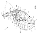
Fig. 2 is a perspective view similar toFig. 1 with portions broken away to show that the tube-support housing includes an airflow-management unit coupled to an underside of the top cover and configured to provide means for managing the flow of air into and out of the tube-support housing and showing that the airflow-management unit is formed to include a central air exhaust passageway that is aligned in fluid communication with the central air-discharge port and sized to contain an umbrella-shaped pressure-relief valve and an offset air intake passageway that is aligned in fluid communication with the upright aspirator tube and sized to contain a duckbill-shaped vacuum-relief valve, and a variable-sized material-collection air chamber that is filled with air and placed in fluid communication with each of the offset air intake passageway and the central air exhaust passageway of the airflow-management unit; -
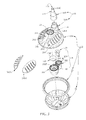
Fig. 3 is an exploded perspective assembly view of the components included in the nasal aspirator ofFigs. 1 and2 showing, from bottom to top, the bowl-shaped elastic deformable squeeze bulb, the ring-shaped rim, a binoculars-shaped valve housing included in the airflow-management unit and formed to include the central air exhaust passageway (on the left) and the offset air intake passageway (on the right), the umbrella-shaped pressure-relief valve that is included in the airflow-management unit and located above the central air exhaust passageways, the duckbill-shaped vacuum-relief valve that is included in the airflow-management unit and located above the offset air intake passageway, the top cover, first and second concave finger grips shown to the left of the top cover, and an upright aspirator tube comprising a base coupled to the top cover and a sleeve separated from the base and formed to include a narrow tip sized to extend into a nasal passageway of a child or other patient; -
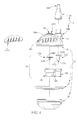
Fig. 4 is a side elevation view of many of the components shown inFig. 3 ; -
Fig. 5 is an enlarged top plan view of the nasal aspirator ofFig. 1 ; -
Fig. 6 is an enlarged sectional view taken along line 6-6 ofFig. 1 showing the elastic deformable squeeze bulb in a normal expanded state, the umbrella-shaped pressure-relief valve in a normal closed flow-blocking position arranged to block discharge of air from the variable-size material-collection air chamber bounded by the squeeze bulb, ring-shaped rim, and top cover, and the duckbill-shaped vacuum-relief valve in a normal closed flow-blocking position arranged to block intake of air from the atmosphere into the air chamber through the upright aspirator tube; -
Fig. 6A is a diagrammatic view suggesting that a caregiver can hold the nasal aspirator between the thumb and the index and middle fingers and apply an upward force using the thumb to deform the elastic deformable squeeze bulb to accomplish the nasal passage aspiration result shown diagrammatically inFig. 8 ; -
Fig. 7 is a diagrammatic view similar toFig. 6 suggesting that the elastic deformable squeeze bulb has been pushed upwardly toward the relatively stationary top cover and compressed by a caregiver squeezing the squeeze bulb to assume a deformed shape to reduce the volume of the air chamber and thereby to force air under pressure out of the air chamber past an opened umbrella-shaped pressure-relief valve and through the central air exhaust passageway and the central air-discharge port; and -
Fig. 8 is a diagrammatic view similar toFig. 7 suggesting that the squeeze bulb has elastically expanded to assume a less compressed and deformed state once the caregiver releases the squeezing grip on the squeeze bulb so as to create a vacuum in the air chamber that is sufficient to move opposing first and second flaps included in the duckbill-shaped vacuum-relief valve apart to an opened position to couple the air chamber and the outer portion of the air intake passageway in fluid communication so that a vacuum is applied to any fluid, tissue, or body material present in the nasal passageway and such material is drawn by suction into the air chamber (along with air in the nasal passageway) through the air intake passageway and past the opened duckbill-shaped vacuum-relief valve and deposited in the air chamber. - According to one embodiment, a
nasal aspirator 10 in accordance with the present disclosure includes a tube-support housing 12, anaspirator tube 14 coupled to tube-support housing 12 to communicate with anair chamber 16 provided in tube-support housing 12, and an airflow-management unit 18 located inair chamber 16 as suggested inFigs. 1 and2 . Airflow-management unit 18 is configured to regulate discharge of air fromair chamber 16 through an air-discharge port 20 formed in tube-support housing 12 and intake of air intoair chamber 16 through a separate air-intake port 22 formed in tube-support housing 12 so that pressurizedair 100 is discharged fromair chamber 16 only through air-discharge port 20 to the atmosphere and never through air-intake port 22 and itscompanion aspirator tube 14 as suggested inFigs. 7 and8 . In an illustrative embodiment, airflow-management unit 18 includes an umbrella-shaped pressure-relief valve 120 associated with air-discharge port 20 and a duckbill-shaped vacuum-relief valve 122 associated with the separate air-intake port 22 as suggested inFigs. 3 and6-8 . - Tube-
support housing 12 includes a dome-shapedtop cover 24, a bowl-shaped elasticdeformable squeeze bulb 26 arranged to underlietop cover 24, and a ring-shaped rim 25 as shown, for example, inFigs. 2 and3 .Rim 25 is arranged to lie between and interconnecttop cover 24 and squeezebulb 26 as suggested inFig. 2 .Top cover 24,squeeze bulb 26, and rim 25 cooperate to formair chamber 16 as suggested inFigs. 2 ,6 , and7 . - Fluid, tissue, and
foreign material 102 extant in anasal passageway 200 of a child or other person may be aspirated intoair chamber 16 of tube-support housing 12 in the following manner as suggested inFigs. 6-8 . A caregiver first compresses squeezebulb 26 as suggested diagrammatically inFig. 7 to pressurize the air inair chamber 16 to a level sufficient to open the normally closed umbrella-shaped pressure-relief valve 120 and discharge pressurizedair 100 fromair chamber 16 through an air-discharge port 20 that is separate and spaced apart fromaspirator tube 14. Then the caregiver releases thesqueeze bulb 26 so that thesqueeze bulb 26 elastically expands from the deformed state shown diagrammatically inFig. 7 to a less deformed state shown diagrammatically inFig. 8 to create a vacuum inair chamber 16 that is sufficient to open the normally closed duckbill vacuum-relief valve 122 and draw bysuction air 101 andmaterial 102 fromnasal passageway 200 throughaspirator tube 14 and airflow-management unit 18 intoair chamber 16. This process can be repeated by the caregiver several times in accordance with the present disclosure to extractmaterial 102 fromnasal passageway 200 without removingaspirator tube 14 from the nose of a child or other person or causing any pressurized air to be discharged into thatnasal passageway 200. -
Top cover 24 is formed to include air-discharge port 20 and the separate air-intake port 22 as suggested inFigs. 1 and2 .Top cover 24 also includes afirst cavity 241 sized to receive a concavefirst finger grip 241G therein and asecond cavity 242 sized to receive a concavesecond finger grip 242G therein as suggested inFigs. 1 and3 .Finger grips top cover 24 for caregivers to place their index and middle fingers when usingnasal aspirator 10 so that their thumb can engage the underside of thesqueeze bulb 26 as suggested inFig. 6A . In an illustrative embodiment,aspirator tube 14 is coupled to one side oftop cover 24 as suggested inFigs. 1-3 to provide a raised island 24I intop cover 24 that is located between concave first andsecond finger grips upright aspirator tube 14 and that is formed to include air-discharge port 20. - In illustrative embodiments,
top cover 24 includes a dome-shaped shell 24S coupled to ring-shaped rim 25 and formed to include anaperture 24A in raised island 24I and around disk 24D arranged to lie inaperture 24A and mate withshell 24S. Disk 24D is formed to include four windows that cooperate to define air-discharge port 20. -
Squeeze bulb 26 is bowl-shaped and made of an elastic deformable plastics material in illustrative embodiments of the present disclosure. When exposed to an external deformation force F applied by acaregiver 28 as suggested inFigs. 6A and7 ,squeeze bulb 26 will deform and change shape from a normal expanded state shown, for example, inFigs. 1A ,2 , and6 to a temporary compressed and deformed state as suggested diagrammatically inFig. 7 to reduce the volume of theair chamber 16 and force some of theair 100 extant inair chamber 16 past a deflectable pliableelastic pad 120P included in an umbrella-shaped pressure-relief valve 120 included in airflow-management unit 18 and out of theair chamber 16 through air-discharge port 20. No pressurized air is discharged fromair chamber 16 through air-intake port 22 andupright aspirator tube 14 owing to the configuration and operation of the normally closed duckbill-shaped vacuum-relief valve 122 included in airflow-management unit 18 and associated with the air-intake port 22 that is coupled toaspirator tube 14. -
Aspirator tube 14 has a free end that is adapted to be inserted into thenasal passageway 200 of a child or other person as suggested diagrammatically inFig. 8 .Aspirator tube 14 is coupled to one side oftop cover 24 of tube-support housing 12 and arranged to extend in an upward direction away fromtop cover 24 as suggested inFigs. 1, 1A , and2 .Aspirator tube 14 is aligned with the air-intake port 22 formed intop cover 24 and formed to include a fluid-conductingpassageway 114 having an inlet 114I formed in anouter tip 14T ofaspirator tube 14 and an outlet 140 opening intoair chamber 16 as suggested inFigs. 2 and6-8 . - In use,
aspirator tube 14 ofnasal aspirator 10 is placed in the nose of a child or other person to extract fluid. A caregiver places two fingers infinger grips aspirator 10 and, with his thumb, applies a compressive force F to squeezebulb 26 by squeezing his fingers together as suggested inFig. 6A . In doing the is, the umbrella-shaped pressure-relief valve 120 is opened as suggested inFig. 7 to allow now pressurizedair 100 to exitair chamber 16 while the duckbill-shaped vacuum-relief valve 122 remains closed. As the caregiver releases the compression on thesqueeze bulb 26, the umbrella-shaped pressure-relief valve 120 closes and the duckbill-shaped vacuum-relief valve 122 opens owing to development of a vacuum (i.e., negative pressure) inair chamber 16 as suggested inFig. 8 . The vacuum inair chamber 16 is sufficient to cause fluid, tissue, andbody material 102 along withair 101 extant in thenasal passageway 200 receiving the top 14T ofaspirator tube 14 to be drawn by suction throughaspirator tube 14 and the opened duckbill-shaped vacuum-relief valve 122 intoair chamber 16 as also suggested inFig. 8 . This process can be repeated multiple times in order to extract material 102 fromnasal passageway 200 without receiving thetip 14T ofaspirator tube 14 fromnasal passageway 200 or discharging any pressurized air exitingair chamber 16 intonasal passageway 200. -
Aspirator tube 14 includes abase 14B and aseparate sleeve 14S in illustrative embodiments of the present disclosure as suggested inFigs. 3 and4 .Base 14B is coupled toshell 24S oftop cover 24 at air-intake port 22 to form a monolithic component as suggested inFigs. 1, 1A ,2 ,3 , and4 .Sleeve 14S is formed to include top 14T and an upper portion of fluid-conductingpassageway 114 and is coupled tobase 14B.Base 14B is formed to include a lower portion of fluid-conductingpassageway 114. - Airflow-
management unit 18 includes a binoculars-shaped valve housing 180 including adischarge tube 181, anintake tube 182 coupled todischarge tube 181 and arranged to lie in side-by-side relation, and atube connector 183 coupled to each oftubes tubes Figs. 3 and4 . Airflow-management unit 18 is coupled totop cover 24 to placedischarge tube 181 in alignment and fluid communication with air-discharge port 20 and to placeintake tube 182 in alignment and fluid communication with air-intake port 22 as suggested inFigs. 2 and6-8 .Discharge tube 181 is formed to include a centralair exhaust passageway 181P extending therethrough and linking air-discharge port 20 in fluid communication toair chamber 16 as suggested inFigs. 2 and6 .Intake tube 182 is formed to include an offsetair intake passageway 182P extending therethrough and linking air-intake port 22 in fluid communication toair chamber 16. - Airflow-
management unit 18 further includes a pressure-relief valve 120 that is mounted in centralair exhaust passageway 181P and configured to be moved automatically from a normally closed position shown inFig. 6 to a temporarily opened position shown inFig. 7 whenever the pressure inair chamber 16 exceeds a predetermined pressure level. This elevated pressure level can be achieved by squeezing thesqueeze bulb 26 by, for example, applying deformation force F to squeezebulb 26. - An illustrative pressure-
relief valve 120 is umbrella-shaped and includes astem 120S mounted in a partition wall 181W arranged to partition centralair exhaust passageway 181P into upper and lower regions and formed to include a series of apertures linking those regions in fluid communication as suggested inFigs. 2 ,3 ,6 , and7 . Pressure-relief valve 120 also includes a pliableelastic pad 120P coupled to an upper end of thestem 120S and arranged to lie in the upper region and move from an undeflected position shown inFig. 6 to a deflected position shown inFig. 7 when the pressure inair chamber 16 exceeds the predetermined pressure level. - Airflow-
management unit 18 also includes a vacuum-relief valve 122 that is mounted in offsetair intake passageway 182P and configured to be moved automatically from a normally closed position shown inFig. 6 to a temporarily opened position shown inFig. 7 whenever a vacuum (i.e., negative pressure) inair chamber 16 exceeds a predetermined negative pressure level. This negative pressure level can be achieved when a caregiver loosens a squeezing grip applied to squeezebulb 26 as suggested diagrammatically inFig. 8 . - An illustrative vacuum-
relief valve 122 is duckbill-shaped and includes movable first andsecond flaps flap anchor 1220 coupled to upper ends of each offlaps flaps air chamber 16 as shown, for example, inFigs. 2 and6-8 . Vacuum-relief valve 122 is configured to provide means for allowing flow of air and fluid materials in only one downward direction towardair chamber 16 ofsqueeze bulb 26 when vacuum-relief valve 122 is opened in response to development of a sufficient vacuum inair chamber 16. Theflaps relief valve 122 are biased elastically normally to mate with one another to lie in undeflected closed positions shown inFig. 6 when there is positive pressure inair chamber 16 and when the vacuum inair chamber 16 is below the predetermined vacuum level. Theflaps air chamber 16 exceeds the predetermined vacuum level. -
Housing 12 includes atop cover 24 formed to include a central air-discharge port 20 and an offset air-intake port 22. Theupright aspirator tube 14 is retained ontop cover 24 to lie in fluid communication with air-intake port 22.Housing 12 further includes an elasticdeformable squeeze bulb 26 that cooperates withtop cover 24 to form a variable-size material-collection air chamber 16 located therebetween to communicate with the separate air-discharge and air-intake ports top cover 24. A ring-shapedrim 25 is arranged to mate with a circular lower edge oftop cover 24 and a circular upper edge ofsqueeze bulb 26 in illustrative embodiments. - An airflow-
management unit 18 is located inair chamber 16 and coupled totop cover 24 to communicate with both of the air-discharge and air-intake ports top cover 24 in illustrative embodiments. Airflow-management unit 18 is configured to provide means for dischargingair 100 from theair chamber 16 through the air-discharge port 20 and then suckingair 101 into theair chamber 16 through the separate air-intake port 22 in response to applying a shape-changing squeezing force F to the elasticdeformable squeeze bulb 26 and then allowing the elasticdeformable squeeze bulb 26 to expand to resume its initial undeformed shape. When afree end 14T ofupright aspirator tube 14 is placed in anasal passageway 200 of a child or other person, nearby fluid, tissue, orforeign material 102 extant in thenasal passageway 200 will be aspirated (i.e., drawn by suction) into theair chamber 16 through the air-intake port 22 formed intop cover 24. - Airflow-
management unit 18 includes an umbrella-shaped pressure-relief valve 120 that is positioned to control the flow of air through the air-discharge port 20 formed intop cover 24 and a duckbill-shaped vacuum-relief valve 122 that is positioned to control the flow of air through the separate air-intake port 22. The umbrella-shaped pressure-relief valve 120 opens only when a caregiver squeezes thesqueeze bulb 26 to increase the pressure of air in theair chamber 16. The duckbill-shaped vacuum-relief valve 122 opens only when a vacuum is created in theair chamber 16 because the caregiver subsequently released thesqueeze bulb 26 to allow thesqueeze bulb 26 elastically to return to its initial undeformed shape. Such a vacuum creates enough suction to open the duckbill-shaped vacuum-relief valve 122 and drawair 101 and nasal-passageway material 102 into theair chamber 16 through theupright aspirator tube 14 and the air-intake port 22. This process can be repeated multiple times to extract material from thenasal passageway 200 without removing theaspirator tube 14 from the child's nose or discharging any pressurized air into the child's nasal cavity. - Airflow-
management unit 18 is coupled to an underside oftop cover 24 and configured to provide means for managing the flow of air into and out of tube-support housing 12. Airflow-management unit 18 is formed to include a centralair exhaust passageway 181P that is aligned with the central air-discharge port 20 and sized to contain an umbrella-shaped pressure-relief valve 120 and an offsetair intake passageway 182P that is aligned with theupright aspirator tube 14 and sized to contain a duckbill-shaped vacuum-relief valve 122. A variable-sized material-collection air chamber 16 is filled with air and placed in fluid communication with each of the offsetair intake passageway 182P and the centralair exhaust passageway 181P of the airflow-management unit 18. - A caregiver can hold the
nasal aspirator 10 between the thumb and the index and middle fingers and apply an upward force F using the thumb as suggested inFig. 6A to deform the elasticdeformable squeeze bulb 26 to accomplish the result shown diagrammatically inFig. 8 . The elasticdeformable squeeze bulb 26 has been pushed upwardly toward thetop cover 24 as suggested inFig. 7 to assume a compressed and deformed shape to reduce the volume of theair chamber 16 and thereby to forceair 100 out ofair chamber 16 past an opened umbrella-shaped pressure-relief valve 120 and through the centralair exhaust passageway 181P and the central air-discharge port 20. Then thesqueeze bulb 26 is released and allowed to expand to a less compressed state so as to create a vacuum in theair chamber 16 that is sufficient to move opposing first andsecond flaps relief valve 122 apart to an opened position to couple theair chamber 16 and the outer portion of theair intake passageway 182P in fluid communication so that a vacuum is applied to anyair 101 and fluid, tissue, orbody material 102 present in thenasal passageway 200 andsuch air 101 andmaterial 102 are drawn into theair chamber 16 through theair intake passageway 182P and past the opened duckbill-shaped vacuum-relief valve 122 and deposited in theair chamber 16. - To summarize, the nasal aspirator comprises an aspirator tube sized to be inserted into the nasal cavity of a person, a housing coupled to the aspirator tube, the housing including a top cover and an elastic deformable squeeze bulb that cooperates with the top cover to form a variable-size material-collection air chamber located therebetween, the top cover formed to include an air-discharge port in fluid communication with the variable-size material-collection air chamber and an offset air-intake port in fluid communication with the aspirator tube, and an airflow-management unit including a pressure-relief valve that is positioned to control the flow of air through the air-discharge port formed in the top cover and a vacuum-relief valve that is positioned to control the flow of air through the offset air-intake port formed in the top cover, the pressure-relief valve opens only when a predetermined pressure level is reached in the air chamber, and the vacuum-relief valve opens only when a predetermined level of vacuum is reached in the air chamber.
- According to one embodiment, the airflow management unit comprises a discharge tube that forms an air exhaust passageway that extends from the air-discharge port into the air chamber and a partition wall arranged in the air exhaust passageway to divide the air exhaust passageway into upper and lower regions, the partition wall is formed to include a series of apertures linking the upper and lower regions in fluid communication, and the pressure-relief valve moves from an undeflected position arranged to block the passage of air through the series of apertures when the pressure in the air chamber is below the predetermined pressure level to a deflected position arranged to allow the passage of air through the series of apertures when the pressure in the air chamber exceeds the predetermined pressure level.
- According to one embodiment, the pressure-relief valve comprises a stem and a pliable elastic pad coupled to the stem so that the pressure-relief valve is umbrella-shaped, the stem is received in the partition wall to couple the pressure-relief valve to the partition wall, and the pliable elastic pad moves from the undeflected position arranged to block the passage of air through the series of apertures when the pressure in the air chamber is below the predetermined pressure level to the deflected position arranged to allow the passage of air through the series of apertures when the pressure in the air chamber exceeds the predetermined pressure level.
- According to one embodiment, the vacuum-relief valve is duckbill-shaped and includes a movable first flap, a movable second flap, and a flap anchor coupled to upper ends of each of the movable first and second flaps, the movable first and second flaps of the duckbill-shaped vacuum-relief valve are biased elastically normally to mate with one another to lie in undeflected closed positions when there is positive pressure in the air chamber and when the vacuum in the air chamber is below the predetermined vacuum level, and the movable first and second flaps are moved apart automatically to assume deflected opened positions when the vacuum the in air chamber exceeds the predetermined vacuum level.
- According to one embodiment, the airflow-management unit includes a valve housing coupled to the top cover of the housing that positions the pressure-relief valve and the vacuum-relief valve relative to the air-discharge port and offset air-intake port formed in the top cover.
- According to one embodiment, the valve housing includes a discharge tube in fluid communication with the air-discharge port that receives the pressure-relief valve and an intake tube in fluid communication with the offset air-intake port that receives the vacuum-relief valve.
- According to one embodiment, the valve housing is binoculars-shaped and includes a tube connector that extends between the discharge tube and the intake tube so that the discharge tube and the intake tube are arranged to lie in side-by-side relation relative to one another.
- In other words the nasal aspirator comprises an aspirator tube sized to be inserted into the nasal cavity of a person, a housing coupled to the aspirator tube, the housing including a top cover and an elastic deformable squeeze bulb that cooperates with the top cover to form a variable-size material-collection air chamber located therebetween, the top cover formed to include an air-discharge port in fluid communication with the variable-size material-collection air chamber and an offset air-intake port in fluid communication with the aspirator tube, and an airflow-management unit including a pressure-relief valve that opens only when a predetermined pressure level is reached in the air chamber, a vacuum-relief valve that opens only when a predetermined vacuum level is reached in the air chamber, and a binoculars-shaped valve housing coupled to the top cover of the housing that receives the pressure-relief valve and the vacuum-relief valve. The binoculars-shaped valve housing is shaped to position the pressure-relief valve to control the flow of air through the air-discharge port and the binoculars-shaped valve housing is shaped to position the vacuum-relief valve to control the flow of air through the offset air-intake port formed in the top cover.
- According to one embodiment, the binoculars-shaped valve housing includes a discharge tube, an intake tube coupled to the discharge tube and arranged to lie in side-by-side relation relative to the discharge tube, and a tube connector coupled to each of tubes and located between the discharge tube and the intake tube.
- According to one embodiment, the discharge tube forms an air exhaust passageway that extends from the air-discharge port into the air chamber, a partition wall is arranged in the air exhaust passageway to divide the air exhaust passageway into upper and lower regions, the partition wall is formed to include a series of apertures linking the upper and lower regions in fluid communication, and the pressure-relief valve moves relative to the partition wall to block or allow the passage of air through the series of apertures.
- According to one embodiment, the pressure-relief valve includes a stem and a pliable elastic pad coupled to the stem so that the pressure-relief valve is umbrella-shaped, the stem is received in the partition wall to couple the pressure-relief valve to the partition wall, and the pliable elastic pad moves from an undeflected position arranged to block the passage of air through the series of apertures when the pressure in the air chamber is below the predetermined pressure level to a deflected position arranged to allow the passage of air through the series of apertures when the pressure in the air chamber exceeds the predetermined pressure level.
- According to one embodiment, the vacuum-relief valve is duckbill-shaped and includes a movable first flap, a movable second flap, and a flap anchor coupled to upper ends of each of the movable first and second flaps and mounted to the intake tube of the binoculars-shaped valve housing.
Claims (10)
- A nasal aspirator adapted to remove fluid or tissue or foreign material from a nasal passageway of a person, the nasal aspirator comprising an aspirator tube sized to be inserted into the nasal cavity of a person and a housing coupled to the aspirator tube,
characterized in that the housing comprises:a top cover and an elastic deformable squeeze bulb that cooperates with the top cover to form a variable-size material-collection air chamber located therebetween, the top cover formed to include an air-discharge port in fluid communication with the variable-size material-collection air chamber and an offset air-intake port in fluid communication with the aspirator tube, andan airflow-management unit located in the air chamber and coupled to the top cover of the housing to communicate with both of the air-discharge and the offset air-intake ports formed in the top cover,the airflow-management unit being configured to provide means for discharging air from the air chamber through the air-discharge port and then drawing air and other materials by suction into the air chamber through the offset air-intake port in response to applying a shape-changing squeezing force to the elastic deformable squeeze bulb and then allowing the elastic deformable squeeze bulb to expand to resume its initial undeformed shape so that when a free end of the upright aspirator tube is placed in the nasal passageway of the person, nearby fluid, tissue, or foreign material extant in the nasal passageway will be drawn by suction into the air chamber through the aspirator tube and the air-intake port formed in the top cover of the housing. - The nasal aspirator of claim 1, wherein the airflow management unit comprises a pressure-relief valve that is positioned to control the flow of air through the air-discharge port formed in the top cover and a vacuum-relief valve that is positioned to control the flow of air through the offset air-intake port formed in the top cover, the pressure-relief valve opens only when the pressure of air in the air chamber is increased in response the shape-changing squeezing force being applied to the elastic deformable squeeze bulb, and the vacuum-relief valve opens only when a vacuum is created in the air chamber in response to the squeeze bulb elastically to returning to its initial undeformed shape.
- The nasal aspirator of claim 2, wherein the airflow management unit comprises a discharge tube that forms an air exhaust passageway that extends from the air-discharge port into the air chamber and a partition wall arranged in the air exhaust passageway to divide the air exhaust passageway into upper and lower regions, the partition wall is formed to include a series of apertures linking the upper and lower regions in fluid communication, and the pressure-relief valve moves from an undeflected position arranged to block the passage of air through the series of apertures when the pressure in the air chamber is below a predetermined pressure level to a deflected position arranged to allow the passage of air through the series of apertures when the pressure in the air chamber exceeds the predetermined pressure level.
- The nasal aspirator of claim 3, wherein the pressure-relief valve comprises a stem and a pliable elastic pad coupled to the stem so that the pressure-relief valve is umbrella-shaped, the stem is received in the partition wall to couple the pressure-relief valve to the partition wall, and the pliable elastic pad moves from the undeflected position arranged to block the passage of air through the series of apertures when the pressure in the air chamber is below the predetermined pressure level to the deflected position arranged to allow the passage of air through the series of apertures when the pressure in the air chamber exceeds the predetermined pressure level.
- The nasal aspirator of claim 2, wherein the vacuum-relief valve is duckbill-shaped and comprises a movable first flap, a movable second flap, and a flap anchor coupled to upper ends of each of the movable first and second flaps, the movable first and second flaps of the duckbill-shaped vacuum-relief valve are biased elastically normally to mate with one another to lie in undeflected closed positions when there is positive pressure in the air chamber and when the vacuum in the air chamber is below a predetermined vacuum level, and the movable first and second flaps are moved apart automatically to assume deflected opened positions when the vacuum in the air chamber exceeds the predetermined vacuum level.
- The nasal aspirator of claim 2, wherein the airflow-management unit comprises a binoculars-shaped valve housing including a discharge tube, an intake tube coupled to the discharge tube and arranged to lie in side-by-side relation relative to the discharge tube, and a tube connector coupled to each of tubes and located between the discharge tube and the intake tube.
- The nasal aspirator of claim 6, wherein the airflow-management unit is coupled to the top cover of the housing to place the discharge tube of the binoculars-shaped valve housing in alignment and fluid communication with the air-discharge port and to place the intake tube of the binoculars-shaped valve housing in alignment and fluid communication with the offset air-intake port.
- The nasal aspirator of claim 1, wherein the top cover comprises a first cavity sized to receive a concave first finger grip therein and a second cavity sized to receive a concave second finger grip therein, the finger grips are arranged to provide a place on the top cover for caregivers to place their index and middle fingers when using the nasal aspirator so that their thumb can engage the underside of the squeeze bulb.
- The nasal aspirator of claim 8, wherein the aspirator tube is coupled to one side of the top cover between the concave first and second finger grips received in the top cover so that the aspirator tube is arranged between the index and middle fingers of a caregiver when the nasal aspirator is used.
- The nasal aspirator of claim 8, wherein the air-discharge port is formed between the concave first and second finger grips received in the top cover so that the air-discharge port is uncovered and arranged between the index and middle fingers of a caregiver when the nasal aspirator is used.
Applications Claiming Priority (1)
| Application Number | Priority Date | Filing Date | Title |
|---|---|---|---|
| US201361806293P | 2013-03-28 | 2013-03-28 |
Publications (2)
| Publication Number | Publication Date |
|---|---|
| EP2783711A1 true EP2783711A1 (en) | 2014-10-01 |
| EP2783711B1 EP2783711B1 (en) | 2017-01-11 |
Family
ID=50389328
Family Applications (1)
| Application Number | Title | Priority Date | Filing Date |
|---|---|---|---|
| EP14162398.3A Not-in-force EP2783711B1 (en) | 2013-03-28 | 2014-03-28 | Nasal aspirator |
Country Status (2)
| Country | Link |
|---|---|
| US (1) | US9656005B2 (en) |
| EP (1) | EP2783711B1 (en) |
Families Citing this family (14)
| Publication number | Priority date | Publication date | Assignee | Title |
|---|---|---|---|---|
| CN104436336A (en) * | 2014-12-24 | 2015-03-25 | 宁波戴维医疗器械股份有限公司 | Nasal aspirator for baby |
| TWI603749B (en) * | 2015-09-21 | 2017-11-01 | 陳郁枝 | Nasal suction device |
| US10398810B2 (en) * | 2015-12-02 | 2019-09-03 | BeeClear, LLC | Nasal suction device |
| US10694895B2 (en) * | 2016-02-03 | 2020-06-30 | Conair Corporation | Food processor having indexing storage containers |
| US10638884B2 (en) * | 2016-02-04 | 2020-05-05 | Conair Corporation | Food processor and sidewall cleaning mechanism therefor |
| US10888673B2 (en) * | 2016-03-29 | 2021-01-12 | Rose Medical Innovations, LLC | Counterbalanced nasal bulb aspirator |
| ES2678420B1 (en) * | 2017-01-09 | 2019-05-20 | Distrosur S A | NASAL VACUUM CLEANING DEVICE |
| WO2019104081A1 (en) * | 2017-11-21 | 2019-05-31 | Doddle & Co, Llc | Hygienic nasal aspirator |
| USD897525S1 (en) * | 2019-03-31 | 2020-09-29 | Ningbo Albert Novosino Co., Ltd | Nasal aspirator |
| CN115671412A (en) * | 2022-07-27 | 2023-02-03 | 丽水市华荟科技有限公司 | Nasal aspirator |
| TWI841299B (en) * | 2023-03-16 | 2024-05-01 | 許淑紅 | Nasal aspirator with adjustable suction power |
| KR102636134B1 (en) * | 2023-07-27 | 2024-02-13 | 김선구 | Apparatus for nasal aspiration |
| US20260083892A1 (en) * | 2024-09-20 | 2026-03-26 | Playhouse Method Inc. | Mucus extraction device and method of use |
| TWI879681B (en) * | 2024-09-26 | 2025-04-01 | 許宏興 | Nasal aspirator |
Citations (5)
| Publication number | Priority date | Publication date | Assignee | Title |
|---|---|---|---|---|
| DE1853713U (en) * | 1962-03-19 | 1962-06-20 | Holger Dr Hesse | MANUAL PUMP FOR SUCTIONING SLIME, BLOOD AND THE LIKE. FROM THE AIRWAY FROM PATIENTS. |
| WO1992000111A1 (en) * | 1990-06-26 | 1992-01-09 | Regent Limited | Mucus extractor |
| CH687851A5 (en) * | 1994-02-09 | 1997-03-14 | Philippe Mougeolle | Instrument for sucking mucus from the noses of babies, young children or the handicapped |
| GB2327062A (en) * | 1997-07-09 | 1999-01-13 | Hamilton Designs Limited | Suction operated seed handling device |
| WO2010126586A1 (en) * | 2009-04-27 | 2010-11-04 | Aardvark Medical, Llc | Irrigation and aspiration devices and methods |
Family Cites Families (14)
| Publication number | Priority date | Publication date | Assignee | Title |
|---|---|---|---|---|
| US2890699A (en) | 1956-06-21 | 1959-06-16 | Laurence W Miller | Nasal suction device |
| US4226233A (en) * | 1978-10-10 | 1980-10-07 | Longevity Products, Inc. | Respirators |
| FR2596277A1 (en) | 1986-03-26 | 1987-10-02 | Bangemann Georges | Suction device for mucus in particular for clearing the noses of children |
| US4921488A (en) | 1988-01-15 | 1990-05-01 | Maitz Carlos A | Aspirator device for body fluids |
| US5848993A (en) * | 1997-08-07 | 1998-12-15 | Deroyal Industries, Inc. | Bulb syringe providing for visual observation of contents thereof and for enhanced deflation/inflation control |
| FR2775602B1 (en) | 1998-03-03 | 2000-05-26 | Philippe Mougeolle | NASAL MUCOSITY SUCTION DEVICE |
| CN2693245Y (en) | 2004-04-04 | 2005-04-20 | 林哥婴儿用品(昆山)有限公司 | Backflow preventing hand-operated nose sucker |
| FR2868322B1 (en) | 2004-04-06 | 2007-05-04 | Incomex Sa Monegasque | APPARATUS FOR MOVING PEOPLE |
| US6994087B1 (en) * | 2004-12-02 | 2006-02-07 | Smith John D | Esophageal intubation detection system |
| US7766886B2 (en) * | 2005-07-30 | 2010-08-03 | The Regents Of The University Of California | Drainage devices and methods |
| US8092434B2 (en) | 2006-08-04 | 2012-01-10 | Med-Systems, Inc. | Device and method for washing nasal passages |
| ES1067564Y (en) | 2007-11-08 | 2008-09-01 | De La Cruz Jose Cobo | VACUUM CLEANER OF THE NASAL SECRETIONS OF THE INFANT WITH A NON-INDUCTIVE DEVICE OF POLLUTION AND TRANSMISSION OF PATHOGEN GERMANS. |
| ES1068572Y (en) | 2008-08-04 | 2009-02-01 | Garcia M Del Carmen Rodriguez | NASAL VACUUM CLEANER DEVICE FOR BABIES AND CHILDREN OF MANUAL OPERATION |
| CH699415A2 (en) | 2008-08-20 | 2010-02-26 | Jean-Luc Dubois | An aspiration of the nasal mucus. |
-
2014
- 2014-03-10 US US14/203,298 patent/US9656005B2/en not_active Expired - Fee Related
- 2014-03-28 EP EP14162398.3A patent/EP2783711B1/en not_active Not-in-force
Patent Citations (5)
| Publication number | Priority date | Publication date | Assignee | Title |
|---|---|---|---|---|
| DE1853713U (en) * | 1962-03-19 | 1962-06-20 | Holger Dr Hesse | MANUAL PUMP FOR SUCTIONING SLIME, BLOOD AND THE LIKE. FROM THE AIRWAY FROM PATIENTS. |
| WO1992000111A1 (en) * | 1990-06-26 | 1992-01-09 | Regent Limited | Mucus extractor |
| CH687851A5 (en) * | 1994-02-09 | 1997-03-14 | Philippe Mougeolle | Instrument for sucking mucus from the noses of babies, young children or the handicapped |
| GB2327062A (en) * | 1997-07-09 | 1999-01-13 | Hamilton Designs Limited | Suction operated seed handling device |
| WO2010126586A1 (en) * | 2009-04-27 | 2010-11-04 | Aardvark Medical, Llc | Irrigation and aspiration devices and methods |
Also Published As
| Publication number | Publication date |
|---|---|
| US20140296793A1 (en) | 2014-10-02 |
| US9656005B2 (en) | 2017-05-23 |
| EP2783711B1 (en) | 2017-01-11 |
Similar Documents
| Publication | Publication Date | Title |
|---|---|---|
| EP2783711B1 (en) | Nasal aspirator | |
| US4764167A (en) | Safety newborn mucous suction device | |
| US5611336A (en) | Single use medical aspirating device and method | |
| US4813932A (en) | Single-handed breast pump | |
| KR100977749B1 (en) | Manual milking machine with stimulating properties | |
| US5215522A (en) | Single use medical aspirating device and method | |
| US8100886B2 (en) | Aspirator assembly | |
| US20080243061A1 (en) | Pump apparatus | |
| EP3854429A1 (en) | Nasal aspirator | |
| GB2245833A (en) | Mucus extractor | |
| JPH05115556A (en) | Sucking device for wound | |
| JP2014500084A (en) | Aspirator and housing cap for aspirator | |
| US2896840A (en) | Air bulb for atomizers and method of making same | |
| US20170281881A1 (en) | Counterbalanced nasal bulb aspirator | |
| CN107427616B (en) | Visible valve system and spill reduction system | |
| CN207461878U (en) | A kind of cup lid | |
| EP0455664B1 (en) | Fluid extractors | |
| CN208927177U (en) | Electronic nose sucking device | |
| WO1989005665A2 (en) | Fluid extractor | |
| CN106540341A (en) | nasal aspirator | |
| CN207506805U (en) | A kind of pressing medical sputum aspirator | |
| CN204501956U (en) | Flying disc type safe transfusion system dropping funnel | |
| CN87200379U (en) | Liquid guiding device | |
| CN219764067U (en) | Airflow control part and handheld suction device | |
| CN221814871U (en) | Negative pressure cupping device |
Legal Events
| Date | Code | Title | Description |
|---|---|---|---|
| 17P | Request for examination filed |
Effective date: 20140328 |
|
| AK | Designated contracting states |
Kind code of ref document: A1 Designated state(s): AL AT BE BG CH CY CZ DE DK EE ES FI FR GB GR HR HU IE IS IT LI LT LU LV MC MK MT NL NO PL PT RO RS SE SI SK SM TR |
|
| AX | Request for extension of the european patent |
Extension state: BA ME |
|
| PUAI | Public reference made under article 153(3) epc to a published international application that has entered the european phase |
Free format text: ORIGINAL CODE: 0009012 |
|
| R17P | Request for examination filed (corrected) |
Effective date: 20150317 |
|
| RBV | Designated contracting states (corrected) |
Designated state(s): AL AT BE BG CH CY CZ DE DK EE ES FI FR GB GR HR HU IE IS IT LI LT LU LV MC MK MT NL NO PL PT RO RS SE SI SK SM TR |
|
| GRAP | Despatch of communication of intention to grant a patent |
Free format text: ORIGINAL CODE: EPIDOSNIGR1 |
|
| INTG | Intention to grant announced |
Effective date: 20160701 |
|
| GRAS | Grant fee paid |
Free format text: ORIGINAL CODE: EPIDOSNIGR3 |
|
| GRAA | (expected) grant |
Free format text: ORIGINAL CODE: 0009210 |
|
| RAP1 | Party data changed (applicant data changed or rights of an application transferred) |
Owner name: DOREL FRANCE |
|
| AK | Designated contracting states |
Kind code of ref document: B1 Designated state(s): AL AT BE BG CH CY CZ DE DK EE ES FI FR GB GR HR HU IE IS IT LI LT LU LV MC MK MT NL NO PL PT RO RS SE SI SK SM TR |
|
| REG | Reference to a national code |
Ref country code: GB Ref legal event code: FG4D |
|
| REG | Reference to a national code |
Ref country code: CH Ref legal event code: EP |
|
| REG | Reference to a national code |
Ref country code: AT Ref legal event code: REF Ref document number: 860677 Country of ref document: AT Kind code of ref document: T Effective date: 20170115 |
|
| REG | Reference to a national code |
Ref country code: IE Ref legal event code: FG4D |
|
| REG | Reference to a national code |
Ref country code: DE Ref legal event code: R096 Ref document number: 602014006122 Country of ref document: DE |
|
| REG | Reference to a national code |
Ref country code: FR Ref legal event code: PLFP Year of fee payment: 4 |
|
| REG | Reference to a national code |
Ref country code: LT Ref legal event code: MG4D |
|
| REG | Reference to a national code |
Ref country code: NL Ref legal event code: MP Effective date: 20170111 |
|
| REG | Reference to a national code |
Ref country code: AT Ref legal event code: MK05 Ref document number: 860677 Country of ref document: AT Kind code of ref document: T Effective date: 20170111 |
|
| PG25 | Lapsed in a contracting state [announced via postgrant information from national office to epo] |
Ref country code: NL Free format text: LAPSE BECAUSE OF FAILURE TO SUBMIT A TRANSLATION OF THE DESCRIPTION OR TO PAY THE FEE WITHIN THE PRESCRIBED TIME-LIMIT Effective date: 20170111 |
|
| PG25 | Lapsed in a contracting state [announced via postgrant information from national office to epo] |
Ref country code: NO Free format text: LAPSE BECAUSE OF FAILURE TO SUBMIT A TRANSLATION OF THE DESCRIPTION OR TO PAY THE FEE WITHIN THE PRESCRIBED TIME-LIMIT Effective date: 20170411 Ref country code: HR Free format text: LAPSE BECAUSE OF FAILURE TO SUBMIT A TRANSLATION OF THE DESCRIPTION OR TO PAY THE FEE WITHIN THE PRESCRIBED TIME-LIMIT Effective date: 20170111 Ref country code: GR Free format text: LAPSE BECAUSE OF FAILURE TO SUBMIT A TRANSLATION OF THE DESCRIPTION OR TO PAY THE FEE WITHIN THE PRESCRIBED TIME-LIMIT Effective date: 20170412 Ref country code: IS Free format text: LAPSE BECAUSE OF FAILURE TO SUBMIT A TRANSLATION OF THE DESCRIPTION OR TO PAY THE FEE WITHIN THE PRESCRIBED TIME-LIMIT Effective date: 20170511 Ref country code: LT Free format text: LAPSE BECAUSE OF FAILURE TO SUBMIT A TRANSLATION OF THE DESCRIPTION OR TO PAY THE FEE WITHIN THE PRESCRIBED TIME-LIMIT Effective date: 20170111 Ref country code: FI Free format text: LAPSE BECAUSE OF FAILURE TO SUBMIT A TRANSLATION OF THE DESCRIPTION OR TO PAY THE FEE WITHIN THE PRESCRIBED TIME-LIMIT Effective date: 20170111 |
|
| PG25 | Lapsed in a contracting state [announced via postgrant information from national office to epo] |
Ref country code: RS Free format text: LAPSE BECAUSE OF FAILURE TO SUBMIT A TRANSLATION OF THE DESCRIPTION OR TO PAY THE FEE WITHIN THE PRESCRIBED TIME-LIMIT Effective date: 20170111 Ref country code: ES Free format text: LAPSE BECAUSE OF FAILURE TO SUBMIT A TRANSLATION OF THE DESCRIPTION OR TO PAY THE FEE WITHIN THE PRESCRIBED TIME-LIMIT Effective date: 20170111 Ref country code: AT Free format text: LAPSE BECAUSE OF FAILURE TO SUBMIT A TRANSLATION OF THE DESCRIPTION OR TO PAY THE FEE WITHIN THE PRESCRIBED TIME-LIMIT Effective date: 20170111 Ref country code: SE Free format text: LAPSE BECAUSE OF FAILURE TO SUBMIT A TRANSLATION OF THE DESCRIPTION OR TO PAY THE FEE WITHIN THE PRESCRIBED TIME-LIMIT Effective date: 20170111 Ref country code: PL Free format text: LAPSE BECAUSE OF FAILURE TO SUBMIT A TRANSLATION OF THE DESCRIPTION OR TO PAY THE FEE WITHIN THE PRESCRIBED TIME-LIMIT Effective date: 20170111 Ref country code: BG Free format text: LAPSE BECAUSE OF FAILURE TO SUBMIT A TRANSLATION OF THE DESCRIPTION OR TO PAY THE FEE WITHIN THE PRESCRIBED TIME-LIMIT Effective date: 20170411 Ref country code: PT Free format text: LAPSE BECAUSE OF FAILURE TO SUBMIT A TRANSLATION OF THE DESCRIPTION OR TO PAY THE FEE WITHIN THE PRESCRIBED TIME-LIMIT Effective date: 20170511 Ref country code: LV Free format text: LAPSE BECAUSE OF FAILURE TO SUBMIT A TRANSLATION OF THE DESCRIPTION OR TO PAY THE FEE WITHIN THE PRESCRIBED TIME-LIMIT Effective date: 20170111 |
|
| REG | Reference to a national code |
Ref country code: DE Ref legal event code: R097 Ref document number: 602014006122 Country of ref document: DE |
|
| PG25 | Lapsed in a contracting state [announced via postgrant information from national office to epo] |
Ref country code: CZ Free format text: LAPSE BECAUSE OF FAILURE TO SUBMIT A TRANSLATION OF THE DESCRIPTION OR TO PAY THE FEE WITHIN THE PRESCRIBED TIME-LIMIT Effective date: 20170111 Ref country code: SK Free format text: LAPSE BECAUSE OF FAILURE TO SUBMIT A TRANSLATION OF THE DESCRIPTION OR TO PAY THE FEE WITHIN THE PRESCRIBED TIME-LIMIT Effective date: 20170111 Ref country code: EE Free format text: LAPSE BECAUSE OF FAILURE TO SUBMIT A TRANSLATION OF THE DESCRIPTION OR TO PAY THE FEE WITHIN THE PRESCRIBED TIME-LIMIT Effective date: 20170111 Ref country code: RO Free format text: LAPSE BECAUSE OF FAILURE TO SUBMIT A TRANSLATION OF THE DESCRIPTION OR TO PAY THE FEE WITHIN THE PRESCRIBED TIME-LIMIT Effective date: 20170111 Ref country code: IT Free format text: LAPSE BECAUSE OF FAILURE TO SUBMIT A TRANSLATION OF THE DESCRIPTION OR TO PAY THE FEE WITHIN THE PRESCRIBED TIME-LIMIT Effective date: 20170111 |
|
| REG | Reference to a national code |
Ref country code: CH Ref legal event code: PL |
|
| PLBE | No opposition filed within time limit |
Free format text: ORIGINAL CODE: 0009261 |
|
| STAA | Information on the status of an ep patent application or granted ep patent |
Free format text: STATUS: NO OPPOSITION FILED WITHIN TIME LIMIT |
|
| PG25 | Lapsed in a contracting state [announced via postgrant information from national office to epo] |
Ref country code: DK Free format text: LAPSE BECAUSE OF FAILURE TO SUBMIT A TRANSLATION OF THE DESCRIPTION OR TO PAY THE FEE WITHIN THE PRESCRIBED TIME-LIMIT Effective date: 20170111 Ref country code: SM Free format text: LAPSE BECAUSE OF FAILURE TO SUBMIT A TRANSLATION OF THE DESCRIPTION OR TO PAY THE FEE WITHIN THE PRESCRIBED TIME-LIMIT Effective date: 20170111 Ref country code: MC Free format text: LAPSE BECAUSE OF FAILURE TO SUBMIT A TRANSLATION OF THE DESCRIPTION OR TO PAY THE FEE WITHIN THE PRESCRIBED TIME-LIMIT Effective date: 20170111 |
|
| 26N | No opposition filed |
Effective date: 20171012 |
|
| REG | Reference to a national code |
Ref country code: IE Ref legal event code: MM4A |
|
| PG25 | Lapsed in a contracting state [announced via postgrant information from national office to epo] |
Ref country code: LU Free format text: LAPSE BECAUSE OF NON-PAYMENT OF DUE FEES Effective date: 20170328 |
|
| PG25 | Lapsed in a contracting state [announced via postgrant information from national office to epo] |
Ref country code: SI Free format text: LAPSE BECAUSE OF FAILURE TO SUBMIT A TRANSLATION OF THE DESCRIPTION OR TO PAY THE FEE WITHIN THE PRESCRIBED TIME-LIMIT Effective date: 20170111 Ref country code: LI Free format text: LAPSE BECAUSE OF NON-PAYMENT OF DUE FEES Effective date: 20170331 Ref country code: IE Free format text: LAPSE BECAUSE OF NON-PAYMENT OF DUE FEES Effective date: 20170328 Ref country code: CH Free format text: LAPSE BECAUSE OF NON-PAYMENT OF DUE FEES Effective date: 20170331 |
|
| REG | Reference to a national code |
Ref country code: BE Ref legal event code: MM Effective date: 20170331 |
|
| REG | Reference to a national code |
Ref country code: FR Ref legal event code: PLFP Year of fee payment: 5 |
|
| PGFP | Annual fee paid to national office [announced via postgrant information from national office to epo] |
Ref country code: GB Payment date: 20180327 Year of fee payment: 5 Ref country code: DE Payment date: 20180323 Year of fee payment: 5 |
|
| PG25 | Lapsed in a contracting state [announced via postgrant information from national office to epo] |
Ref country code: BE Free format text: LAPSE BECAUSE OF NON-PAYMENT OF DUE FEES Effective date: 20170331 |
|
| PGFP | Annual fee paid to national office [announced via postgrant information from national office to epo] |
Ref country code: FR Payment date: 20180328 Year of fee payment: 5 |
|
| PG25 | Lapsed in a contracting state [announced via postgrant information from national office to epo] |
Ref country code: MT Free format text: LAPSE BECAUSE OF NON-PAYMENT OF DUE FEES Effective date: 20170328 |
|
| PG25 | Lapsed in a contracting state [announced via postgrant information from national office to epo] |
Ref country code: HU Free format text: LAPSE BECAUSE OF FAILURE TO SUBMIT A TRANSLATION OF THE DESCRIPTION OR TO PAY THE FEE WITHIN THE PRESCRIBED TIME-LIMIT; INVALID AB INITIO Effective date: 20140328 |
|
| REG | Reference to a national code |
Ref country code: DE Ref legal event code: R119 Ref document number: 602014006122 Country of ref document: DE |
|
| PG25 | Lapsed in a contracting state [announced via postgrant information from national office to epo] |
Ref country code: CY Free format text: LAPSE BECAUSE OF NON-PAYMENT OF DUE FEES Effective date: 20170111 |
|
| GBPC | Gb: european patent ceased through non-payment of renewal fee |
Effective date: 20190328 |
|
| PG25 | Lapsed in a contracting state [announced via postgrant information from national office to epo] |
Ref country code: MK Free format text: LAPSE BECAUSE OF FAILURE TO SUBMIT A TRANSLATION OF THE DESCRIPTION OR TO PAY THE FEE WITHIN THE PRESCRIBED TIME-LIMIT Effective date: 20170111 |
|
| PG25 | Lapsed in a contracting state [announced via postgrant information from national office to epo] |
Ref country code: DE Free format text: LAPSE BECAUSE OF NON-PAYMENT OF DUE FEES Effective date: 20191001 Ref country code: GB Free format text: LAPSE BECAUSE OF NON-PAYMENT OF DUE FEES Effective date: 20190328 |
|
| PG25 | Lapsed in a contracting state [announced via postgrant information from national office to epo] |
Ref country code: FR Free format text: LAPSE BECAUSE OF NON-PAYMENT OF DUE FEES Effective date: 20190331 |
|
| PG25 | Lapsed in a contracting state [announced via postgrant information from national office to epo] |
Ref country code: TR Free format text: LAPSE BECAUSE OF FAILURE TO SUBMIT A TRANSLATION OF THE DESCRIPTION OR TO PAY THE FEE WITHIN THE PRESCRIBED TIME-LIMIT Effective date: 20170111 |
|
| PG25 | Lapsed in a contracting state [announced via postgrant information from national office to epo] |
Ref country code: AL Free format text: LAPSE BECAUSE OF FAILURE TO SUBMIT A TRANSLATION OF THE DESCRIPTION OR TO PAY THE FEE WITHIN THE PRESCRIBED TIME-LIMIT Effective date: 20170111 |
|
| P01 | Opt-out of the competence of the unified patent court (upc) registered |
Effective date: 20230527 |