EP2783595A1 - Electric makeup brush - Google Patents
Electric makeup brush Download PDFInfo
- Publication number
- EP2783595A1 EP2783595A1 EP12851256.3A EP12851256A EP2783595A1 EP 2783595 A1 EP2783595 A1 EP 2783595A1 EP 12851256 A EP12851256 A EP 12851256A EP 2783595 A1 EP2783595 A1 EP 2783595A1
- Authority
- EP
- European Patent Office
- Prior art keywords
- electric
- makeup brush
- bristles
- applicator
- brush according
- Prior art date
- Legal status (The legal status is an assumption and is not a legal conclusion. Google has not performed a legal analysis and makes no representation as to the accuracy of the status listed.)
- Withdrawn
Links
- 230000033001 locomotion Effects 0.000 claims abstract description 39
- 239000002537 cosmetic Substances 0.000 claims abstract description 20
- 239000000463 material Substances 0.000 claims abstract description 19
- 238000006243 chemical reaction Methods 0.000 claims description 12
- 238000000034 method Methods 0.000 claims description 11
- 238000011156 evaluation Methods 0.000 description 14
- 230000000694 effects Effects 0.000 description 12
- 230000002349 favourable effect Effects 0.000 description 11
- 230000008878 coupling Effects 0.000 description 8
- 238000010168 coupling process Methods 0.000 description 8
- 238000005859 coupling reaction Methods 0.000 description 8
- 230000003796 beauty Effects 0.000 description 4
- 238000005259 measurement Methods 0.000 description 4
- 238000003780 insertion Methods 0.000 description 3
- 230000037431 insertion Effects 0.000 description 3
- 241000555745 Sciuridae Species 0.000 description 2
- 230000000052 comparative effect Effects 0.000 description 2
- 238000010348 incorporation Methods 0.000 description 2
- -1 polybutylene terephthalate Polymers 0.000 description 2
- 229920001707 polybutylene terephthalate Polymers 0.000 description 2
- 229920000139 polyethylene terephthalate Polymers 0.000 description 2
- 239000005020 polyethylene terephthalate Substances 0.000 description 2
- 241000283690 Bos taurus Species 0.000 description 1
- 241000282461 Canis lupus Species 0.000 description 1
- 241000283707 Capra Species 0.000 description 1
- 241000282693 Cercopithecidae Species 0.000 description 1
- 241000282994 Cervidae Species 0.000 description 1
- 241000282326 Felis catus Species 0.000 description 1
- 241001465754 Metazoa Species 0.000 description 1
- 241001504654 Mustela nivalis Species 0.000 description 1
- 239000004677 Nylon Substances 0.000 description 1
- 241000283973 Oryctolagus cuniculus Species 0.000 description 1
- 241001494479 Pecora Species 0.000 description 1
- 241000555742 Petaurista leucogenys Species 0.000 description 1
- 235000008331 Pinus X rigitaeda Nutrition 0.000 description 1
- 241000018646 Pinus brutia Species 0.000 description 1
- 235000011613 Pinus brutia Nutrition 0.000 description 1
- 241000282330 Procyon lotor Species 0.000 description 1
- 241001416503 Sciurus carolinensis Species 0.000 description 1
- 241000282898 Sus scrofa Species 0.000 description 1
- 241000282485 Vulpes vulpes Species 0.000 description 1
- 238000013459 approach Methods 0.000 description 1
- 238000005452 bending Methods 0.000 description 1
- 230000017531 blood circulation Effects 0.000 description 1
- 238000011161 development Methods 0.000 description 1
- 239000000203 mixture Substances 0.000 description 1
- 229920001778 nylon Polymers 0.000 description 1
- 229920002994 synthetic fiber Polymers 0.000 description 1
- 239000012209 synthetic fiber Substances 0.000 description 1
- 238000012360 testing method Methods 0.000 description 1
Images



Classifications
-
- A—HUMAN NECESSITIES
- A46—BRUSHWARE
- A46B—BRUSHES
- A46B13/00—Brushes with driven brush bodies or carriers
- A46B13/02—Brushes with driven brush bodies or carriers power-driven carriers
- A46B13/023—Brushes with driven brush bodies or carriers power-driven carriers with means for inducing vibration to the bristles
-
- A—HUMAN NECESSITIES
- A46—BRUSHWARE
- A46B—BRUSHES
- A46B13/00—Brushes with driven brush bodies or carriers
- A46B13/02—Brushes with driven brush bodies or carriers power-driven carriers
-
- A—HUMAN NECESSITIES
- A45—HAND OR TRAVELLING ARTICLES
- A45D—HAIRDRESSING OR SHAVING EQUIPMENT; EQUIPMENT FOR COSMETICS OR COSMETIC TREATMENTS, e.g. FOR MANICURING OR PEDICURING
- A45D33/00—Containers or accessories specially adapted for handling powdery toiletry or cosmetic substances
- A45D33/34—Powder-puffs, e.g. with installed container
- A45D33/36—Powder-puffs, e.g. with installed container with handle
-
- A—HUMAN NECESSITIES
- A45—HAND OR TRAVELLING ARTICLES
- A45D—HAIRDRESSING OR SHAVING EQUIPMENT; EQUIPMENT FOR COSMETICS OR COSMETIC TREATMENTS, e.g. FOR MANICURING OR PEDICURING
- A45D34/00—Containers or accessories specially adapted for handling liquid toiletry or cosmetic substances, e.g. perfumes
- A45D34/04—Appliances specially adapted for applying liquid, e.g. using roller or ball
- A45D34/042—Appliances specially adapted for applying liquid, e.g. using roller or ball using a brush or the like
-
- A—HUMAN NECESSITIES
- A46—BRUSHWARE
- A46B—BRUSHES
- A46B9/00—Arrangements of the bristles in the brush body
- A46B9/02—Position or arrangement of bristles in relation to surface of the brush body, e.g. inclined, in rows, in groups
- A46B9/021—Position or arrangement of bristles in relation to surface of the brush body, e.g. inclined, in rows, in groups arranged like in cosmetics brushes, e.g. mascara, nail polish, eye shadow
-
- A—HUMAN NECESSITIES
- A45—HAND OR TRAVELLING ARTICLES
- A45D—HAIRDRESSING OR SHAVING EQUIPMENT; EQUIPMENT FOR COSMETICS OR COSMETIC TREATMENTS, e.g. FOR MANICURING OR PEDICURING
- A45D33/00—Containers or accessories specially adapted for handling powdery toiletry or cosmetic substances
- A45D2033/001—Accessories
-
- A—HUMAN NECESSITIES
- A45—HAND OR TRAVELLING ARTICLES
- A45D—HAIRDRESSING OR SHAVING EQUIPMENT; EQUIPMENT FOR COSMETICS OR COSMETIC TREATMENTS, e.g. FOR MANICURING OR PEDICURING
- A45D34/00—Containers or accessories specially adapted for handling liquid toiletry or cosmetic substances, e.g. perfumes
- A45D2034/002—Accessories
Definitions
- the present invention relates to an electric makeup brush that causes an applicator formed of bundled bristles to be reciprocally vibrated in a direction in which the bristles are oriented with an electric drive unit such that the applicator dabs cosmetic material onto the skin with the tip of the bristles.
- Patent Documents 1 and 2 Since powdered cosmetic materials such as foundation are applied to a relatively large area of skin, it is of importance to develop a makeup application tool that enables uniform application in a short period of time and an even and beautiful finish. Therefore, in recent years, electrically-operated makeup brushes as a makeup application tool for applying powdered cosmetic material such as foundation have been developed (Patent Documents 1 and 2).
- Development is desired for an electrically-operated makeup tool to enable, through electric operation, a motion different from makeup work performed by hand, an excellent finish of makeup relative to when performed by hand, and an excellent feeling upon contact with the skin that has not been conventionally achievable, in addition to enabling reduction in time without dirtying the hand through electric operation.
- An object of the present invention is to provide an electrically-operated makeup tool to enable, through electric operation, a motion different from makeup work performed by hand, an excellent finish of makeup relative to when performed by hand that has not been conventionally achievable, and a comfortable feeling upon contact with the skin, in addition to enabling application of powdered cosmetic material in a short period of time without dirtying the hand.
- powdered cosmetic material can be applied uniformly in a short period of time without dirtying the hand with an excellent feeling upon contact with the skin and that an excellent cosmetic effect is obtained by causing an applicator formed of bundled bristles to be reciprocally vibrated in a direction in which the bristles are oriented with an electric drive unit such that the applicator dabs the cosmetic material onto the skin with the tip of the bristles.
- the present invention is an electric makeup brush that causes an applicator formed of bundled bristles to reciprocally vibrate in a direction in which the bristles are oriented with an electric drive unit such that the applicator dabs cosmetic material onto a skin with the tip of the bristles.
- the present invention is the electric makeup brush wherein the drive unit includes an electric motor, a speed reduction mechanism for reducing rotation of the electric motor, and a reciprocating motion conversion mechanism that converts rotation reduced by the speed reduction mechanism into reciprocating motion.
- the present invention is the electric makeup brush wherein the reciprocating motion conversion mechanism includes a cam mechanism that converts rotation reduced by the speed reduction mechanism into reciprocating motion in a direction identical or orthogonal to a rotating shaft.
- the present invention is the electric makeup brush wherein the cam mechanism includes a push spring for biasing an arm to cause contact with a cam.
- the present invention is the electric makeup brush wherein the reciprocating motion conversion mechanism includes a crank mechanism that converts rotation reduced by the speed reduction mechanism into reciprocating motion in a direction orthogonal to a rotating shaft.
- the present invention is the electric makeup brush wherein an amplitude of the reciprocal vibration is 2 to 10 mm.
- the present invention is the electric makeup brush wherein a vibration frequency of the reciprocal vibration is 3 to 50 Hz.
- the present invention is the electric makeup brush wherein a length of each of the bristles is 15 to 30 mm.
- the present invention is the electric makeup brush wherein an outer diameter of the applicator is 10 to 35 mm.
- the present invention is the electric makeup brush wherein a tip surface of the applicator has a flat shape.
- the present invention is the electric makeup brush wherein a tip surface of the applicator has a flat shape inclined with respect to the direction in which the bristles are oriented.
- the present invention is a makeup method including using the electric makeup brush described above to dab cosmetic material onto a skin with the tip of the bristles.
- powdered cosmetic material such as foundation can be dabbed onto the skin with the tip of the bristles, and it is possible to obtain a makeup effect of a uniform and beautiful finish with excellent durability.
- Fig. 1 shows the external appearance of the electric makeup brush of the present invention.
- a switch (7) provided to a body (6) of an electric makeup brush (1) of the present invention is turned on, an electric drive unit built in the body (6) is activated to reciprocally vibrate an applicator (4) formed of bundled bristles (3) in a direction in which the bristles (3) are oriented, so that the applicator can dab cosmetic material onto the skin with the tip of the bristles.
- a bristle of synthetic fiber such as polybutylene terephthalate (PBT), polyethylene terephthalate (PET), or nylon, use of a blend thereof, and the like are acceptable.
- PBT polybutylene terephthalate
- PET polyethylene terephthalate
- nylon use of a blend thereof, and the like.
- the applicator without particular limitation, as long as the rigidity is approximately the same as that of a conventional makeup brush.
- the load for pushing and bending the applicator by 0 to 8 mm is preferably in a range of 0 to 10 N, so that there is excellent flexibility and an excellent fit and feeling on the skin.
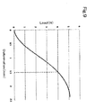
- the deformation amount upon application of 4 N of load on the applicator is approximately 1.5 mm as shown in Fig. 9 , for example, so that the there is a favorable balance in the ease of application and touch on the skin from vibration.
- a drive unit (2) includes an electric motor (9), a speed reduction mechanism (10) for reducing the rotation of the electric motor, and a reciprocating motion conversion mechanism (11) that converts rotation reduced by the speed reduction mechanism into reciprocating motion.
- a dry cell (8) is built in the body (6). When the switch (7) is turned on, the electric motor (9) is activated to activate the drive unit (2).
- the speed reduction mechanism (10) is a mechanism for reducing the rotation of the electric motor (9) up to rotation of an appropriate rotation speed through use of the gear ratio of a plurality of gears.
- a first gear (10a) attached to a rotating shaft (9a) of the electric motor (9) is engaged with a second gear (10b), and the rotation of the electric motor is transmitted to the second gear.
- the first gear (10a) and the second gear (10b) are bevel gears to convert the rotation of the electric motor (9) into rotation of a rotating shaft orthogonal to the rotating shaft (9a). Accordingly, the speed reduction mechanism (10) and the electric motor (9) can be aligned in the shaft center direction of the rotating shaft (9a) of the electric motor (9) to allow the body (6) to be in a rod shape that is excellent in portability.
- a third gear (10c) is a gear with a smaller number of teeth and a smaller diameter than the second gear (10b) and is coupled with the same rotating shaft as the second gear (10b).
- the third gear (10c) is engaged with a fourth gear (10d) with a larger number of teeth and a larger diameter than the third gear.
- the gear ratio of the third gear and the fourth gear allows the rotation speed to be reduced.
- a fifth gear (10e) with a small number of teeth and a small diameter is coupled.
- the fifth gear (10e) engaging with a sixth gear (10f) with a larger number of teeth and a larger diameter the rotation speed is further reduced.
- the speed reduction mechanism (10) the rotation of the electric motor that is about 6000 rpm in rotation speed is eventually reduced to about 180 to 3000 rpm in rotation speed.
- Figs. 2(a), 2(b) , 3(a) and 3(b) show the speed reduction mechanism (10) using six gears. This is for incorporation into the body (6) with a thin rod shape that is excellent in portability. By using and combining a plurality of gears that are relatively small in outer diameter to allow incorporation into the body (6), the rotation speed is reduced in a step-like manner. Note that since the shape of the body (6) differs depending on the usage or method of use of the electric makeup brush, the number or type of gears to be used in the speed reduction mechanism should be selected appropriately.
- the reciprocating motion conversion mechanism (11) is a mechanism for converting rotation reduced by the speed reduction mechanism (10) into reciprocating motion.
- the sixth gear (10f) and a rotating plate (10g) for which the rotating shaft is the same are coupled in a position eccentric from the rotating shaft of plate side surfaces (10h and 10i) that face each other by a contact pin (11b) arranged to be parallel to the rotating shaft.
- An arm (11a) that contacts the contact pin (11b) upon rotation of the sixth gear (10f) is fixed to a vibrating member (12) through an insertion hole (6a) provided to the body (6).
- the arm (11a) has an inclined surface that is curved. This is a contact surface (11d) for contact with the contact pin (11b).
- a push spring (11c) is incorporated and biased such that repulsion of the spring causes the arm (11a) to contact the contact pin (11b).
- an external thread section (13a) is provided to be screwed into and coupled with an applicator holding body (5) provided with an internal thread section (13b) on the inner circumferential surface.
- the applicator (4) in which bristles oriented in the vibrating direction of the vibrating member (12) are bundled is fixed on the opposite side of the vibrating member (12).
- the configuration is such that, when the vibrating member (12) vibrates reciprocally, the applicator (4) is caused to vibrate reciprocally in the direction in which the bristles (3) are oriented.
- Coupling of the vibrating member (12) and the applicator holding body (5) by screwing is one example for detachably joining the applicator (4) and the applicator holding body (5) to the vibrating member (12), in case replacement of the applicator (4) becomes necessary due to wear of bristles or the like.
- a method other than screwing may be employed appropriately as a method for detachable joining.
- the vibrating member (12) and the applicator holding body (5) may be formed integrally.
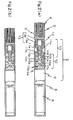
- Figs. 2(a) and 2(b) are transparent views of the electric makeup brush of the present invention seen from the front
- Figs. 3(a) and 3(b) are transparent views seen from the side
- Figs. 2(a) and 3(a) as well as Figs. 2(b) and 3(b) respectively show corresponding states
- Figs. 3(a) and 3(b) show an example in which the sixth gear (10f) rotates in the counterclockwise direction. When the sixth gear (10f) rotates, the arm (11a) starts to contact the contact pin (11b) from the state of Fig. 3(a) ( Fig. 2(a) ).
- the arm (11a) moves in the right direction in the drawing along with the movement of the contact pin (11b).
- the arm (11a) With an inclined surface that is curved as the contact surface for the contact pin and bias by the push spring (11c), the arm (11a) can follow the rotating motion of the contact pin (11b) smoothly, and the rotating motion of the sixth gear (10f) can be converted into reciprocating motion.
- the arm (11a) moves in the right direction in the drawing up to the state of Fig. 3(b) ( Fig. 2(b) ).
- engagement with the contact pin (11b) is released, and the arm (11a) and the vibrating member (12) coupled therewith quickly moves in the left direction in the drawing due to repulsion by the push spring (11c).
- the applicator (4) is projected for a dab on the skin with the tip of the bristles.
- the repulsion of the push spring (11c) biases the arm (11a), causes the arm (11a) to contact the contact pin (11b), and, in the case where engagement of the arm (11a) and the contact pin (11b) is released, acts as a force for quickly moving the applicator (4) for a dab on the skin with the tip of the bristles. Since the force of the spring is used for a dab on the skin in this manner, a comfortable sense of use can be obtained without applying a strong force on the skin. Due to the push spring (11c) being incorporated, excess force is not transmitted to the sixth gear (10f) even in the case where a user presses the electric makeup brush against the skin with a strong force upon use, for example. Therefore, it is possible to avoid a risk of failure in the speed reduction mechanism (10) or the electric motor (9).
- a cam is formed by coupling plate side surfaces (10h and 10i) of the sixth gear (10f) and the rotating plate (10g) that face each other with the contact pin (11b) parallel to the rotating shaft, and the arm (11a) that contacts the cam (contact pin (11b)) is combined to convert the rotating motion of the sixth gear (10f) into reciprocating motion in a direction orthogonal to the rotating shaft.
- the shape of the cam is not limited to that shown in the drawing.
- a plate cam as shown in Fig. 6(a) may be attached to a rotating shaft of a gear for use.
- the rotating motion of the gear (10f) can be converted into reciprocating motion in a direction orthogonal to the rotating shaft also by providing a crank mechanism (14) to the reciprocating motion conversion mechanism (11), as shown in Fig. 5 .
- the crank mechanism is formed by coupling one end of a coupling rod (14a) in a position eccentric from the rotating shaft of the fourth gear (10d) and further coupling a rod (14b) rotatably to the other end of the coupling rod (14a).
- a bush (15) is a member for restricting the rod (14b) in the vibrating direction through insertion of the rod (14b) and reducing friction with the body (6) caused by the reciprocal vibration of the rod (14b).
- an adjustment dial or the like for changing the applied voltage or the like may be provided to the body (6) so that the rotation speed of the electric motor can be appropriately adjusted at the time of use by a user.
- the amplitude (stroke length) may be adjusted through a change in the moving distance of the arm (11a) or the coupling rod (14a) in the reciprocating motion by increasing the diameter of a rotating body such as the sixth gear (10f) shown in Figs. 2(a) and 2(b) or the fourth gear (10d) shown in Fig.
- the results of comparison of the electric makeup brush of the present invention with a conventional makeup method are shown in Table 1.
- the evaluations are all an average of questionnaire evaluations conducted upon application of foundation by three panelists and are indicated as Excellent, Good, Normal, or Bad.
- Fig. 7(a) For the shape of the tip of the applicator, three types of “inclined flat surface” ( Fig. 7(a) ) that is a flat surface inclined with respect to the direction in which the bristles are oriented, “perpendicular flat surface” ( Fig. 7(b) ) that is a flat surface perpendicular to the direction in which the bristles are oriented, and “curved surface” ( Fig. 7(c) ) for which the tips of the bristles are cut and aligned in a mound shape were evaluated.
- the length of the bristles is a value of measurement for a longest bristle length L1 and a shortest bristle length L2 for "inclined flat surface” ( Fig. 7(a) ), a bristle length L for "perpendicular flat surface” ( Fig. 7(b) ), and the longest bristle length L1 and the shortest bristle length L2 for "curved surface” ( Fig. 7(c) ).
- the outer diameter of the applicator is a value of measurement for the outer diameter of the bundled bristles or of measurement of a major axis D1 and a minor axis D2 in the case of an elliptical shape ( Fig. 8 ).
- Example 1 Condition and evaluation item Comparative Example 1 (conventional makeup method)
- Example 2 Example 3
- Example 4 Example 5 Characteristics of brush Shape of tip of applicator Inclined flat surface Inclined flat surface Inclined flat surface Perpendicular flat surface Perpendicular flat surface Curved surface Length of bristle (mm) 18-15 18-15 20-16 18 15 20-3 0 Outer diameter of applicator (mm) 20 20 20-10 20 28-17 23 Characteristics of vibration Vibration frequency (times per minute) - 1200 1200 1200 1200 1200 Stroke (mm) - 3 3 3 3 3 3 3
- Evaluation item Sense of use Normal Excellent Excellent Good Good Excellent Capability for quick finish Normal Excellent Excellent Excellent Excellent Excellent Applicability to fine portions Normal Good Excellent Good Good Good Good Beauty of finish Normal Good Good Good Good Normal Overall rating Normal Excellent Excellent Good Good Good Good Good
- the shape of the applicator of the electric makeup brush for each evaluation is as shown in Fig. 7(a) .
- the applicator used is cylinder-shaped with an outer diameter of 20 mm, a flat inclined surface as the tip surface, 18 mm in length (L1) for a longer bristle, and 15 mm in length (L2) for a shorter bristle.
- Sense of use feeling and softness on the skin
- the electric makeup brush of the present invention has a soft touch on the skin, and favorable results were confirmed with evaluation results of Excellent to Good under all conditions. Note that when the stroke length (amplitude) is less than 2 mm, the moving distance of the applicator is slight. Therefore, vibration was absorbed by the deformation of skin or bristle, the tip of the bristles did not come off the skin, and the effect of the present invention that is application through dabbing on the skin was not obtained sufficiently.
- the results were favorable at Good with 2 to 7 mm in stroke length and ordinary at Normal with 10 mm.
- a normal or greater effect can be obtained with a stroke length of 2 to 10mm.
- the stroke length is preferably 2 to 7 mm.
Landscapes
- Brushes (AREA)
Abstract
Description
- The present invention relates to an electric makeup brush that causes an applicator formed of bundled bristles to be reciprocally vibrated in a direction in which the bristles are oriented with an electric drive unit such that the applicator dabs cosmetic material onto the skin with the tip of the bristles.
- Since powdered cosmetic materials such as foundation are applied to a relatively large area of skin, it is of importance to develop a makeup application tool that enables uniform application in a short period of time and an even and beautiful finish. Therefore, in recent years, electrically-operated makeup brushes as a makeup application tool for applying powdered cosmetic material such as foundation have been developed (
Patent Documents 1 and 2). - These electrically-operated makeup brushes have an effect of enabling application without dirtying the hand in a shorter period of time than application by hand in a conventional manner and a massaging effect through an increase in blood circulation. However, the basic motions of the makeup brushes do not differ greatly from the motion conventionally performed by hand. Therefore, a significant effect in contrast to a case of application by hand has not been necessarily expectable in the finish of makeup.
- Development is desired for an electrically-operated makeup tool to enable, through electric operation, a motion different from makeup work performed by hand, an excellent finish of makeup relative to when performed by hand, and an excellent feeling upon contact with the skin that has not been conventionally achievable, in addition to enabling reduction in time without dirtying the hand through electric operation.
- Patent Document 1: Japanese Patent Application Laid-open No.
2006-192074 - Patent Document 2: Japanese Patent Application Laid-open No.
2006-238998 - An object of the present invention is to provide an electrically-operated makeup tool to enable, through electric operation, a motion different from makeup work performed by hand, an excellent finish of makeup relative to when performed by hand that has not been conventionally achievable, and a comfortable feeling upon contact with the skin, in addition to enabling application of powdered cosmetic material in a short period of time without dirtying the hand.
- As a result a study conducted in order to achieve the above object, the inventors of the present invention have found that powdered cosmetic material can be applied uniformly in a short period of time without dirtying the hand with an excellent feeling upon contact with the skin and that an excellent cosmetic effect is obtained by causing an applicator formed of bundled bristles to be reciprocally vibrated in a direction in which the bristles are oriented with an electric drive unit such that the applicator dabs the cosmetic material onto the skin with the tip of the bristles.
- That is, the present invention is an electric makeup brush that causes an applicator formed of bundled bristles to reciprocally vibrate in a direction in which the bristles are oriented with an electric drive unit such that the applicator dabs cosmetic material onto a skin with the tip of the bristles.
- Further, the present invention is the electric makeup brush wherein the drive unit includes an electric motor, a speed reduction mechanism for reducing rotation of the electric motor, and a reciprocating motion conversion mechanism that converts rotation reduced by the speed reduction mechanism into reciprocating motion.
- Further, the present invention is the electric makeup brush wherein the reciprocating motion conversion mechanism includes a cam mechanism that converts rotation reduced by the speed reduction mechanism into reciprocating motion in a direction identical or orthogonal to a rotating shaft.
- Further, the present invention is the electric makeup brush wherein the cam mechanism includes a push spring for biasing an arm to cause contact with a cam.
- Also, the present invention is the electric makeup brush wherein the reciprocating motion conversion mechanism includes a crank mechanism that converts rotation reduced by the speed reduction mechanism into reciprocating motion in a direction orthogonal to a rotating shaft.
- Further, the present invention is the electric makeup brush wherein an amplitude of the reciprocal vibration is 2 to 10 mm.
- Further, the present invention is the electric makeup brush wherein a vibration frequency of the reciprocal vibration is 3 to 50 Hz.
- Further, the present invention is the electric makeup brush wherein a length of each of the bristles is 15 to 30 mm.
- Further, the present invention is the electric makeup brush wherein an outer diameter of the applicator is 10 to 35 mm.
- Further, the present invention is the electric makeup brush wherein a tip surface of the applicator has a flat shape.
- Further, the present invention is the electric makeup brush wherein a tip surface of the applicator has a flat shape inclined with respect to the direction in which the bristles are oriented.
- Also, the present invention is a makeup method including using the electric makeup brush described above to dab cosmetic material onto a skin with the tip of the bristles.
- With the electric makeup brush of the present invention, powdered cosmetic material such as foundation can be dabbed onto the skin with the tip of the bristles, and it is possible to obtain a makeup effect of a uniform and beautiful finish with excellent durability.
- Feeling upon contact with the skin is excellent, and it is possible to apply powdered cosmetic material uniformly over the entire face in a short period of time without dirtying the hand.
-
-
Fig. 1 is an external view of an electric makeup brush; -
Figs 2(a) and 2(b) are transparent front views of the electric makeup brush (Fig. 2(a) of a state where an applicator is projected, andFig. 2(b) of a state where the applicator is drawn in); -
Figs 3(a) and 3(b) are transparent side views of the electric makeup brush (Fig. 3(a) of a state where an applicator is projected, andFig. 3(b) of a state where the applicator is drawn in); -
Fig. 4 is an exploded view of main components of the electric makeup brush; -
Fig. 5 is an exploded view of main components of an electric makeup brush (of a second embodiment); -
Figs. 6(a) to 6(c) are shapes of a cam (Fig. 6(a) of the second embodiment,Fig. 6(b) of a third embodiment, andFig. 6(c) of a fourth embodiment); -
Figs. 7(a) to 7(c) are views showing the shape of the applicator (Fig. 7(a) with an inclined flat surface,Fig. 7(b) with a perpendicular flat surface, andFig. 7(c) with a curved surface); -
Fig. 8 is a view showing a dimensional measurement portion of the applicator; and -
Fig. 9 is a graph showing the relationship of the deformation amount and load of the applicator. - An electric makeup brush of the present invention will be described in detail based on the drawings.
-
Fig. 1 shows the external appearance of the electric makeup brush of the present invention. When a switch (7) provided to a body (6) of an electric makeup brush (1) of the present invention is turned on, an electric drive unit built in the body (6) is activated to reciprocally vibrate an applicator (4) formed of bundled bristles (3) in a direction in which the bristles (3) are oriented, so that the applicator can dab cosmetic material onto the skin with the tip of the bristles. - For the material of the bristle, use of horsehair that has been conventionally used in makeup brushes or hair of an animal such as a weasel, gray squirrel, pine squirrel, Canadian squirrel, goat, raccoon, deer, cattle, sheep, rabbit, monkey, cat, fox, pig, wolf, or Japanese giant flying squirrel, use of a bristle of synthetic fiber such as polybutylene terephthalate (PBT), polyethylene terephthalate (PET), or nylon, use of a blend thereof, and the like are acceptable.
- There is a wide range of choice for the applicator without particular limitation, as long as the rigidity is approximately the same as that of a conventional makeup brush. However, when load is applied to the tip of the bristles to push and bend the applicator, the load for pushing and bending the applicator by 0 to 8 mm is preferably in a range of 0 to 10 N, so that there is excellent flexibility and an excellent fit and feeling on the skin. For the electric makeup brush of the present invention, it is particularly preferable that the deformation amount upon application of 4 N of load on the applicator is approximately 1.5 mm as shown in
Fig. 9 , for example, so that the there is a favorable balance in the ease of application and touch on the skin from vibration. - As shown in
Figs. 2(a) and 2(b) , a drive unit (2) includes an electric motor (9), a speed reduction mechanism (10) for reducing the rotation of the electric motor, and a reciprocating motion conversion mechanism (11) that converts rotation reduced by the speed reduction mechanism into reciprocating motion. A dry cell (8) is built in the body (6). When the switch (7) is turned on, the electric motor (9) is activated to activate the drive unit (2). - The speed reduction mechanism (10) is a mechanism for reducing the rotation of the electric motor (9) up to rotation of an appropriate rotation speed through use of the gear ratio of a plurality of gears. As shown in
Figs. 2(a) and 2(b) andFigs. 3(a) and 3(b) (Figs. 2(a) and 2(b) showing transparent views from the front andFigs. 3(a) and 3(b) transparent views from the side), a first gear (10a) attached to a rotating shaft (9a) of the electric motor (9) is engaged with a second gear (10b), and the rotation of the electric motor is transmitted to the second gear. In the drawing, the first gear (10a) and the second gear (10b) are bevel gears to convert the rotation of the electric motor (9) into rotation of a rotating shaft orthogonal to the rotating shaft (9a). Accordingly, the speed reduction mechanism (10) and the electric motor (9) can be aligned in the shaft center direction of the rotating shaft (9a) of the electric motor (9) to allow the body (6) to be in a rod shape that is excellent in portability. - A third gear (10c) is a gear with a smaller number of teeth and a smaller diameter than the second gear (10b) and is coupled with the same rotating shaft as the second gear (10b). The third gear (10c) is engaged with a fourth gear (10d) with a larger number of teeth and a larger diameter than the third gear. The gear ratio of the third gear and the fourth gear allows the rotation speed to be reduced. At the rotating shaft of the fourth gear (10d), a fifth gear (10e) with a small number of teeth and a small diameter is coupled. By the fifth gear (10e) engaging with a sixth gear (10f) with a larger number of teeth and a larger diameter, the rotation speed is further reduced. With the speed reduction mechanism (10), the rotation of the electric motor that is about 6000 rpm in rotation speed is eventually reduced to about 180 to 3000 rpm in rotation speed.
-
Figs. 2(a), 2(b) ,3(a) and 3(b) show the speed reduction mechanism (10) using six gears. This is for incorporation into the body (6) with a thin rod shape that is excellent in portability. By using and combining a plurality of gears that are relatively small in outer diameter to allow incorporation into the body (6), the rotation speed is reduced in a step-like manner. Note that since the shape of the body (6) differs depending on the usage or method of use of the electric makeup brush, the number or type of gears to be used in the speed reduction mechanism should be selected appropriately. - The reciprocating motion conversion mechanism (11) is a mechanism for converting rotation reduced by the speed reduction mechanism (10) into reciprocating motion. As shown in
Fig. 4 , the sixth gear (10f) and a rotating plate (10g) for which the rotating shaft is the same are coupled in a position eccentric from the rotating shaft of plate side surfaces (10h and 10i) that face each other by a contact pin (11b) arranged to be parallel to the rotating shaft. - An arm (11a) that contacts the contact pin (11b) upon rotation of the sixth gear (10f) is fixed to a vibrating member (12) through an insertion hole (6a) provided to the body (6). The arm (11a) has an inclined surface that is curved. This is a contact surface (11d) for contact with the contact pin (11b). Between the vibrating member (12) and the body (6), a push spring (11c) is incorporated and biased such that repulsion of the spring causes the arm (11a) to contact the contact pin (11b).
- On the outer circumferential surface of the vibrating member (12), an external thread section (13a) is provided to be screwed into and coupled with an applicator holding body (5) provided with an internal thread section (13b) on the inner circumferential surface. At the applicator holding body (5), the applicator (4) in which bristles oriented in the vibrating direction of the vibrating member (12) are bundled is fixed on the opposite side of the vibrating member (12). The configuration is such that, when the vibrating member (12) vibrates reciprocally, the applicator (4) is caused to vibrate reciprocally in the direction in which the bristles (3) are oriented. Coupling of the vibrating member (12) and the applicator holding body (5) by screwing is one example for detachably joining the applicator (4) and the applicator holding body (5) to the vibrating member (12), in case replacement of the applicator (4) becomes necessary due to wear of bristles or the like. Thus, a method other than screwing may be employed appropriately as a method for detachable joining. In the case where replacement of the applicator is not necessary, the vibrating member (12) and the applicator holding body (5) may be formed integrally.
-
Figs. 2(a) and 2(b) are transparent views of the electric makeup brush of the present invention seen from the front, andFigs. 3(a) and 3(b) are transparent views seen from the side.Figs. 2(a) and3(a) as well asFigs. 2(b) and3(b) respectively show corresponding states.Figs. 3(a) and 3(b) show an example in which the sixth gear (10f) rotates in the counterclockwise direction. When the sixth gear (10f) rotates, the arm (11a) starts to contact the contact pin (11b) from the state ofFig. 3(a) (Fig. 2(a) ). When the sixth gear (10f) rotates further in the counterclockwise direction, the arm (11a) moves in the right direction in the drawing along with the movement of the contact pin (11b). With an inclined surface that is curved as the contact surface for the contact pin and bias by the push spring (11c), the arm (11a) can follow the rotating motion of the contact pin (11b) smoothly, and the rotating motion of the sixth gear (10f) can be converted into reciprocating motion. - Along with the rotation of the sixth gear (10f), the arm (11a) moves in the right direction in the drawing up to the state of
Fig. 3(b) (Fig. 2(b) ). However, when the sixth gear (10f) rotates further, engagement with the contact pin (11b) is released, and the arm (11a) and the vibrating member (12) coupled therewith quickly moves in the left direction in the drawing due to repulsion by the push spring (11c). Along with this movement, the applicator (4) is projected for a dab on the skin with the tip of the bristles. In this manner, the repulsion of the push spring (11c) biases the arm (11a), causes the arm (11a) to contact the contact pin (11b), and, in the case where engagement of the arm (11a) and the contact pin (11b) is released, acts as a force for quickly moving the applicator (4) for a dab on the skin with the tip of the bristles. Since the force of the spring is used for a dab on the skin in this manner, a comfortable sense of use can be obtained without applying a strong force on the skin. Due to the push spring (11c) being incorporated, excess force is not transmitted to the sixth gear (10f) even in the case where a user presses the electric makeup brush against the skin with a strong force upon use, for example. Therefore, it is possible to avoid a risk of failure in the speed reduction mechanism (10) or the electric motor (9). - In the cam mechanism (11) in
Figs. 2(a), 2(b) ,3(a), and 3(c) , a cam is formed by coupling plate side surfaces (10h and 10i) of the sixth gear (10f) and the rotating plate (10g) that face each other with the contact pin (11b) parallel to the rotating shaft, and the arm (11a) that contacts the cam (contact pin (11b)) is combined to convert the rotating motion of the sixth gear (10f) into reciprocating motion in a direction orthogonal to the rotating shaft. However, the shape of the cam is not limited to that shown in the drawing. For example, a plate cam as shown inFig. 6(a) may be attached to a rotating shaft of a gear for use. By using an end cam (Fig. 6(b) ) or a cylindrical rib cam (Fig. 6(c) ), it is possible to convert the rotating motion of the sixth gear (10f) into reciprocating motion in the same direction as the rotating shaft, and the direction in which the applicator vibrates can be changed. - The rotating motion of the gear (10f) can be converted into reciprocating motion in a direction orthogonal to the rotating shaft also by providing a crank mechanism (14) to the reciprocating motion conversion mechanism (11), as shown in
Fig. 5 . The crank mechanism is formed by coupling one end of a coupling rod (14a) in a position eccentric from the rotating shaft of the fourth gear (10d) and further coupling a rod (14b) rotatably to the other end of the coupling rod (14a). A bush (15) is a member for restricting the rod (14b) in the vibrating direction through insertion of the rod (14b) and reducing friction with the body (6) caused by the reciprocal vibration of the rod (14b). - As an approach of changing the vibration frequency, there is a method of changing the voltage applied to the electric motor or changing the pulse width through PWM control to change the rotation speed of the electric motor. Although not shown in the drawing, an adjustment dial or the like for changing the applied voltage or the like may be provided to the body (6) so that the rotation speed of the electric motor can be appropriately adjusted at the time of use by a user. The amplitude (stroke length) may be adjusted through a change in the moving distance of the arm (11a) or the coupling rod (14a) in the reciprocating motion by increasing the diameter of a rotating body such as the sixth gear (10f) shown in
Figs. 2(a) and 2(b) or the fourth gear (10d) shown inFig. 5 that is immediately before the conversion of rotating motion into reciprocating motion, changing the shape of the contact surface for the arm in the case where a cam with a shape as shown inFigs. 6(a) to 6(c) is used as a rotating body, or the like. - The results of a test conducted in order to confirm the effect of the electric makeup brush of the present invention will be described below in detail.
- The results of comparison of the electric makeup brush of the present invention with a conventional makeup method (method of applying foundation with a normal technique using a normal makeup brush) are shown in Table 1. The evaluations are all an average of questionnaire evaluations conducted upon application of foundation by three panelists and are indicated as Excellent, Good, Normal, or Bad.
- For the shape of the tip of the applicator, three types of "inclined flat surface" (
Fig. 7(a) ) that is a flat surface inclined with respect to the direction in which the bristles are oriented, "perpendicular flat surface" (Fig. 7(b) ) that is a flat surface perpendicular to the direction in which the bristles are oriented, and "curved surface" (Fig. 7(c) ) for which the tips of the bristles are cut and aligned in a mound shape were evaluated. - The length of the bristles is a value of measurement for a longest bristle length L1 and a shortest bristle length L2 for "inclined flat surface" (
Fig. 7(a) ), a bristle length L for "perpendicular flat surface" (Fig. 7(b) ), and the longest bristle length L1 and the shortest bristle length L2 for "curved surface" (Fig. 7(c) ). - The outer diameter of the applicator is a value of measurement for the outer diameter of the bundled bristles or of measurement of a major axis D1 and a minor axis D2 in the case of an elliptical shape (
Fig. 8 ).[Table 1] Condition and evaluation item Comparative Example 1 (conventional makeup method) Example 1 Example 2 Example 3 Example 4 Example 5 Characteristics of brush Shape of tip of applicator Inclined flat surface Inclined flat surface Inclined flat surface Perpendicular flat surface Perpendicular flat surface Curved surface Length of bristle (mm) 18-15 18-15 20-16 18 15 20-3 0 Outer diameter of applicator (mm) 20 20 20-10 20 28-17 23 Characteristics of vibration Vibration frequency (times per minute) - 1200 1200 1200 1200 1200 Stroke (mm) - 3 3 3 3 3 Evaluation item Sense of use Normal Excellent Excellent Good Good Excellent Capability for quick finish Normal Excellent Excellent Excellent Excellent Excellent Applicability to fine portions Normal Good Excellent Good Good Good Beauty of finish Normal Good Good Good Good Normal Overall rating Normal Excellent Excellent Good Good Good - As shown in Table 1, favorable results were obtained for all of Examples 1 to 5 compared to the conventional makeup method (comparative example 1) using a normal makeup brush. Particularly for Examples 1 and 2 in which the shape of the tip of the applicator is "inclined flat surface," high evaluations were obtained due to the applicability to fine portions. Thus, it was confirmed that a cosmetic effect is further enhanced by causing the shape of the tip of the applicator to be an inclined flat shape. When the outer diameter of the applicator exceeds 35 mm, it is difficult to apply cosmetic material to fine portions, and the beauty of finish is affected. Thus, the outer diameter of the applicator is preferably 35 mm or less.
- Next, the sense of use such as the feeling of the applicator upon contact with the skin in the case where the vibration frequency and the stroke length (amplitude) of the electric makeup brush are changed were evaluated.
- The shape of the applicator of the electric makeup brush for each evaluation is as shown in
Fig. 7(a) . The applicator used is cylinder-shaped with an outer diameter of 20 mm, a flat inclined surface as the tip surface, 18 mm in length (L1) for a longer bristle, and 15 mm in length (L2) for a shorter bristle.[Table 2] Sense of use (feeling and softness on the skin) Vibration frequency Stroke (mm) (Times per minute) (Hz) 2 3 5 7 10 200 3.3 Good Good Good Good Good 400 6.7 Good Excellent Good Good Good 600 10 Good Excellent Good Excellent Good 800 13.3 Good Excellent Excellent Excellent Good 1200 20 Excellent Excellent Excellent Excellent Excellent 2500 41.7 Good Good Good Good Good - As shown in Table 2, the electric makeup brush of the present invention has a soft touch on the skin, and favorable results were confirmed with evaluation results of Excellent to Good under all conditions. Note that when the stroke length (amplitude) is less than 2 mm, the moving distance of the applicator is slight. Therefore, vibration was absorbed by the deformation of skin or bristle, the tip of the bristles did not come off the skin, and the effect of the present invention that is application through dabbing on the skin was not obtained sufficiently.
- When the vibration frequency exceeds 50 Hz, vibration of the applicator was not felt, and the effect of application through dabbing on the skin with the tip of the bristles was not obtained.
- Next, the results of evaluation for beauty of finish are shown in Table 3.
[Table 3] Beauty of finish Vibration frequency Stroke (mm) (Times per minute) (Hz) 2 3 5 7 10 200 3.3 Good Good Normal Normal Normal 400 6.7 Good Good Good Normal Normal 600 10 Good Good Good Good Good 800 13.3 Good Good Excellent Excellent Good 1200 20 Good Good Excellent Excellent Excellent 2500 41.7 Good Excellent Excellent Excellent Excellent - As shown in Table 3, there are many favorable results of Good distributed in a range of 2 to 10 mm in stroke length and 3.3 to 41.7 Hz in vibration frequency. Particularly, there are many extremely favorable results of Excellent distributed in a range of 13.3 to 41.7 Hz in vibration frequency and 3 to 7 mm in stroke length. Note that, with a vibration frequency exceeding 50 Hz, the motion of dabbing on the skin with the tip of the bristles cannot be performed reliably, and a favorable result was not obtained.
- The results of evaluation for the effect of enabling a quick finish of makeup are shown in
Fig. 4 .[Table 4] Capability for quick finish Vibration frequency Stroke (mm) (Times per minute) (Hz) 2 3 5 7 10 200 3.3 Good Normal Normal Normal Normal 400 6.7 Good Good Good Normal Normal 600 10 Good Good Excellent Good Good 800 13.3 Good Good Excellent Excellent Good 1200 20 Excellent Excellent Excellent Excellent Excellent 2500 41.7 Good Excellent Excellent Excellent Excellent - For the effect of enabling a quick finish of makeup, as shown in Table 4, there are many favorable results of Good distributed in a range of 2 to 10 mm in stroke length and 3.3 to 41.7 Hz in vibration frequency. Particularly, there are many extremely favorable results of Excellent distributed in a range of 13.3 to 41.7 Hz in vibration frequency and 3 to 7 mm in stroke length. In this manner, it was confirmed that a region of a relatively large vibration frequency tends to be advantageous in the finish of makeup. When the vibration frequency is smaller than 3 Hz, makeup cannot be finished quickly. The vibration frequency is preferably 3 Hz or greater.
- The results of evaluation for ease of application to fine portions are shown in Table 5.
[Table 5] Applicability to fine portions Vibration frequency Stroke (mm) (Times per minute) (Hz) 2 3 5 7 10 200 3.3 Good Good Good Good Normal 400 6.7 Good Good Good Good Normal 600 10 Good Good Good Good Normal 800 13.3 Good Good Good Good Normal 1200 20 Good Good Good Good Normal 2500 41.7 Good Good Good Good Normal - For the ease of application to fine portions, as shown in Table 5, the results were favorable at Good with 2 to 7 mm in stroke length and ordinary at Normal with 10 mm. A normal or greater effect can be obtained with a stroke length of 2 to 10mm. For application to fine portions, the stroke length is preferably 2 to 7 mm.
- The overall evaluations summarizing the respective evaluations above are shown in Table 6.
[Table 6] Overall rating Vibration frequency Stroke (mm) (Times per minute) (Hz) 2 3 5 7 10 200 3.3 Good Good Normal Normal Normal 400 6.7 Good Good Good Normal Normal 600 10 Good Good Good Good Good 800 13.3 Good Good Excellent Excellent Good 1200 20 Excellent Excellent Excellent Excellent Excellent 2500 41.7 Good Excellent Excellent Excellent Good - As shown in Table 6, there are many favorable results of Good distributed in a range of 2 to 10 mm in stroke length and 3.3 to 41.7 Hz in vibration frequency. Particularly, there are many extremely favorable results of Excellent distributed in a range of 13.3 to 41.7 Hz in vibration frequency and 2 to 10 mm in stroke length. Note that the results above are evaluations for a case where foundation is applied. It is possible that evaluations differ from those described above in the case of applying powdered cosmetic material such as oshiroi or blush that differs in formula from foundation. Therefore, for application of various powdered cosmetic materials with the electric makeup brush, it is desirable that a mechanism capable of adjusting the stroke length and vibration frequency be provided. Upon applying foundation, use with an appropriate adjustment within the range described above is preferable.
-
- 1
- Electric makeup brush
- 2
- Drive unit
- 3
- Bristle
- 4
- Applicator
- 5
- Applicator holding body
- 6
- Body
- 6a
- Insertion hole
- 7
- Switch
- 8
- Dry cell
- 9
- Electric motor
- 9a
- Rotating shaft
- 10
- Speed reduction mechanism
- 10a
- First gear
- 10b
- Second gear
- 10c
- Third gear
- 10d
- Fourth gear
- 10e
- Fifth gear
- 10f
- Sixth gear
- 10g
- Rotating plate
- 10h
- Plate side surface
- 10i
- Plate side surface
- 11
- Cam mechanism (reciprocating motion conversion mechanism)
- 11a
- Arm
- 11b
- Contact pin
- 11c
- Push spring
- 11d
- Contact surface
- 12
- Vibrating member
- 13
- Screwing section
- 13a
- External thread section
- 13b
- Internal thread section
- 14
- Crank mechanism (reciprocating motion conversion mechanism)
- 14a
- Coupling rod
- 14b
- Rod
- 15
- Bush
Claims (12)
- An electric makeup brush that causes an applicator formed of bundled bristles to reciprocally vibrate in a direction in which the bristles are oriented with an electric drive unit such that the applicator dabs cosmetic material onto a skin with the tip of the bristles.
- The electric makeup brush according to claim 1, wherein the drive unit includes an electric motor, a speed reduction mechanism for reducing rotation of the electric motor, and a reciprocating motion conversion mechanism that converts rotation reduced by the speed reduction mechanism into reciprocating motion.
- The electric makeup brush according to claim 2, wherein the reciprocating motion conversion mechanism includes a cam mechanism that converts rotation reduced by the speed reduction mechanism into reciprocating motion in a direction identical or orthogonal to a rotating shaft.
- The electric makeup brush according to claim 3, wherein the cam mechanism includes a push spring for biasing an arm to cause contact with a cam.
- The electric makeup brush according to claim 2, wherein the reciprocating motion conversion mechanism includes a crank mechanism that converts rotation reduced by the speed reduction mechanism into reciprocating motion in a direction orthogonal to a rotating shaft.
- The electric makeup brush according to any one of claims 1 to 5, wherein an amplitude of the reciprocal vibration is 2 to 10 mm.
- The electric makeup brush according to any one of claims 1 to 6, wherein a vibration frequency of the reciprocal vibration is 3 to 50 Hz.
- The electric makeup brush according to any one of claims 1 to 7, wherein a length of each of the bristles is 15 to 30 mm.
- The electric makeup brush according to any one of claims 1 to 8, wherein an outer diameter of the applicator is 10 to 35 mm.
- The electric makeup brush according to any one of claims 1 to 9, wherein a tip surface of the applicator has a flat shape.
- The electric makeup brush according to any one of claims 1 to 10, wherein a tip surface of the applicator has a flat shape inclined with respect to the direction in which the bristles are oriented.
- A makeup method, comprising using the electric makeup brush according to any one of claims 1 to 11 to dab cosmetic material onto a skin with the tip of the bristles.
Applications Claiming Priority (2)
| Application Number | Priority Date | Filing Date | Title |
|---|---|---|---|
| JP2011253392A JP5270747B2 (en) | 2011-11-21 | 2011-11-21 | Electric makeup brush |
| PCT/JP2012/079925 WO2013077284A1 (en) | 2011-11-21 | 2012-11-19 | Electric makeup brush |
Publications (2)
| Publication Number | Publication Date |
|---|---|
| EP2783595A1 true EP2783595A1 (en) | 2014-10-01 |
| EP2783595A4 EP2783595A4 (en) | 2015-08-05 |
Family
ID=48469728
Family Applications (1)
| Application Number | Title | Priority Date | Filing Date |
|---|---|---|---|
| EP12851256.3A Withdrawn EP2783595A4 (en) | 2011-11-21 | 2012-11-19 | Electric makeup brush |
Country Status (8)
| Country | Link |
|---|---|
| US (1) | US20150034113A1 (en) |
| EP (1) | EP2783595A4 (en) |
| JP (1) | JP5270747B2 (en) |
| KR (1) | KR20140094546A (en) |
| CN (1) | CN103957746A (en) |
| HK (1) | HK1199611A1 (en) |
| TW (1) | TW201332484A (en) |
| WO (1) | WO2013077284A1 (en) |
Cited By (2)
| Publication number | Priority date | Publication date | Assignee | Title |
|---|---|---|---|---|
| WO2019183764A1 (en) | 2018-03-26 | 2019-10-03 | Braun Gmbh | Skin treatment device |
| WO2019183765A1 (en) | 2018-03-26 | 2019-10-03 | Braun Gmbh | Interface for attaching a brush to a skin treatment device |
Families Citing this family (51)
| Publication number | Priority date | Publication date | Assignee | Title |
|---|---|---|---|---|
| US9427065B2 (en) * | 2013-07-12 | 2016-08-30 | Herman David Palmieri | Reciprocating rotating vibrating bidirectional electric cosmetic applicator |
| USD721503S1 (en) * | 2013-07-15 | 2015-01-27 | Koninklijke Philips N.V. | Facial cleaning apparatus |
| USD794962S1 (en) * | 2013-07-15 | 2017-08-22 | Koniklijke Philips N.V. | Facial cleaning apparatus with stand |
| FR3014655B1 (en) * | 2013-12-13 | 2016-11-25 | Oreal | COSMETIC PRODUCT APPLICATION DEVICE |
| FR3014649B1 (en) * | 2013-12-13 | 2016-11-25 | Oreal | COSMETIC PRODUCT APPLICATION DEVICE |
| US9775976B2 (en) * | 2013-12-17 | 2017-10-03 | L'oreal | Skin cleansing apparatus with oscillation motion converter |
| US9462873B2 (en) | 2014-07-15 | 2016-10-11 | L'oreal | Cosmetic formulation dispensing head for a personal care appliance |
| US10772473B2 (en) | 2014-08-13 | 2020-09-15 | Nse Products, Inc. | Device and method for cleansing and treating skin |
| USD778065S1 (en) | 2014-08-13 | 2017-02-07 | Nse Products, Inc. | Treatment brush head |
| USD757441S1 (en) * | 2014-12-09 | 2016-05-31 | F.S. Korea Industries Inc | Cosmetic brush head |
| WO2016137994A1 (en) * | 2015-02-24 | 2016-09-01 | Anisa International Inc. | Collection of oval-shaped brushes and method for using same |
| EP3291763B1 (en) | 2015-05-04 | 2019-05-15 | Trisa Holding AG | Electric appliance for personal care |
| USD829445S1 (en) | 2015-08-13 | 2018-10-02 | Nse Products, Inc. | Treatment brush head |
| CN108366664B (en) * | 2015-08-13 | 2021-03-19 | Nse 产品公司 | Apparatus and method for cleansing and caring for skin |
| USD782197S1 (en) | 2015-08-13 | 2017-03-28 | Nse Products, Inc. | Treatment brush head |
| USD787190S1 (en) * | 2015-09-29 | 2017-05-23 | Worth Beauty, Llc | Makeup brush |
| US10624448B2 (en) | 2015-10-02 | 2020-04-21 | Worth Beauty, Llc | Computerized cosmetics brushes |
| US10881194B2 (en) | 2015-10-02 | 2021-01-05 | Worth Beauty, Llc | Computerized cosmetics brushes |
| USD787192S1 (en) * | 2015-12-10 | 2017-05-23 | F.S. Korea Industries Inc. | Cosmetic brush |
| FR3045298B1 (en) * | 2015-12-17 | 2018-01-26 | L'oreal | APPARATUS FOR TREATING HUMAN KERATINIC MATERIALS |
| EP3184094B1 (en) | 2015-12-22 | 2019-10-30 | Braun GmbH | Massage device |
| CN105639991A (en) * | 2016-01-28 | 2016-06-08 | 胡发刚 | Brush special for applying vitiligo covering liquid |
| US10368630B2 (en) * | 2016-02-05 | 2019-08-06 | Si/Tko Holdings, Inc. | Adjustable cosmetic brush system |
| US10022025B2 (en) | 2016-05-20 | 2018-07-17 | Chirp Products, LLC | Dual motor cleansing brush |
| CN110325076B (en) * | 2017-02-20 | 2021-10-26 | 迈克·托德美容有限合伙公司 | Sound wave cosmetic brush |
| CN110636880A (en) | 2017-05-25 | 2019-12-31 | Nse 产品公司 | TENS attachment for devices for cleaning and treating skin |
| WO2019014573A1 (en) | 2017-07-13 | 2019-01-17 | Chirp Products LLC | Cleansing brush head |
| JP7040746B2 (en) | 2017-08-28 | 2022-03-23 | 株式会社トキワ | Cosmetic container |
| US10598230B2 (en) | 2017-09-29 | 2020-03-24 | L'oreal | Drive shaft coupling |
| US11470940B2 (en) | 2017-09-29 | 2022-10-18 | L'oreal | Formula delivery device |
| US11278099B2 (en) | 2017-09-29 | 2022-03-22 | L'oreal | Formula delivery appliance |
| US11291284B2 (en) | 2017-09-29 | 2022-04-05 | L'oreal | Formula delivery head |
| USD871079S1 (en) * | 2018-03-29 | 2019-12-31 | F. S. Korea Industries Inc. | Cosmetic brush |
| US10349729B1 (en) * | 2018-05-02 | 2019-07-16 | Ayesha Adam Cheema | Multi-tip brush tool |
| CN109156973A (en) * | 2018-11-03 | 2019-01-08 | 广州市华晟健康产业有限公司 | It is a kind of for smearing the device of cosmetics |
| USD935195S1 (en) * | 2019-01-24 | 2021-11-09 | Anisa International, Inc | Scooped cosmetics applicator |
| USD905968S1 (en) * | 2019-01-24 | 2020-12-29 | Anisa International, Inc. | Scooped cosmetics applicator |
| USD905969S1 (en) * | 2019-01-24 | 2020-12-29 | Anisa International, Inc. | Scooped cosmetics applicator |
| US10786339B1 (en) * | 2019-07-12 | 2020-09-29 | Sdc U.S. Smilepay Spv | Hygienic brush |
| USD929743S1 (en) | 2019-07-31 | 2021-09-07 | Anisa International, Inc. | Cosmetics brush head with reservoirs |
| USD929742S1 (en) | 2019-07-31 | 2021-09-07 | Anisa International, Inc. | Cosmetics brush head with tube |
| USD929744S1 (en) | 2019-09-13 | 2021-09-07 | Anisa International, Inc. | Cosmetics brush head with reservoirs |
| USD940464S1 (en) * | 2019-09-20 | 2022-01-11 | Anisa International, Inc. | Cosmetics brush head with reservoirs |
| US12023491B2 (en) | 2020-04-03 | 2024-07-02 | Nse Products, Inc. | Modulated waveform treatment device and method |
| USD933840S1 (en) | 2020-04-21 | 2021-10-19 | Nse Products, Inc. | Microcurrent skin treatment device |
| US12239196B2 (en) | 2021-02-26 | 2025-03-04 | L'oreal | Control systems, devices, and methods for formulation delivery |
| US11534263B2 (en) | 2021-02-26 | 2022-12-27 | L'oreal | Formulation delivery systems, devices, and methods |
| US11712099B2 (en) | 2021-02-26 | 2023-08-01 | L'oreal | Reusable cartridge systems, devices, and methods |
| JP2023130612A (en) * | 2022-03-08 | 2023-09-21 | 三菱ケミカル株式会社 | Brush, method for producing coated food using the same, method for forming a coat, and method for shipping food |
| USD1013392S1 (en) * | 2022-09-19 | 2024-02-06 | Max Sauer Sas | Cosmetic brush |
| US20250040686A1 (en) * | 2023-07-31 | 2025-02-06 | L’Oreal | Cosmetic securement device for stabilization and rotation of cosmetic applicator configured for users with limited mobility |
Family Cites Families (15)
| Publication number | Priority date | Publication date | Assignee | Title |
|---|---|---|---|---|
| US766970A (en) * | 1903-09-21 | 1904-08-09 | Vibras Sage Company | Massage-machine. |
| US1352894A (en) * | 1919-04-10 | 1920-09-14 | Fred G Hoffine | Vibrator |
| US3978852A (en) * | 1975-04-07 | 1976-09-07 | Annoni Jerry D | Plaque jack toothbrush |
| JPS60109429U (en) * | 1983-12-29 | 1985-07-25 | カネボウ株式会社 | electric patting brush |
| JPH0139462Y2 (en) * | 1984-10-16 | 1989-11-27 | ||
| KR200365249Y1 (en) * | 2004-07-28 | 2004-10-21 | 추윤정 | An electric puff |
| JP2006192074A (en) * | 2005-01-13 | 2006-07-27 | Makoto Kobayashi | Ultrasonic vibration type applicator |
| FR2882506B1 (en) * | 2005-02-25 | 2007-05-18 | Oreal | MAKE-UP PROCESS USING A VIBRANT APPLICATOR |
| JP2006238998A (en) | 2005-03-01 | 2006-09-14 | Key Tranding Co Ltd | Electromotive cosmetic equipment |
| US20070151061A1 (en) * | 2005-12-30 | 2007-07-05 | Gregory Mink | Applicator brush with cylindrical ferrule and angled tip |
| FR2929496B1 (en) * | 2008-04-08 | 2011-01-28 | Oreal | VIBRATION APPLICATOR WITH SELECTIVE ORIENTATION OF VIBRATIONS |
| US8562352B2 (en) * | 2008-07-09 | 2013-10-22 | Andrea B. Fairweather | Systems, methods and apparatus involving Fairweather faces cosmetics brushes and face charts |
| JP2011087675A (en) * | 2009-10-21 | 2011-05-06 | Shiseido Co Ltd | Cosmetic brush and makeup method using the same |
| US20120124758A1 (en) * | 2010-11-19 | 2012-05-24 | Markus Sabisch | Powered brush |
| KR101142078B1 (en) * | 2011-10-31 | 2012-05-14 | 주식회사하이첸 | Puff device for cosmetics |
-
2011
- 2011-11-21 JP JP2011253392A patent/JP5270747B2/en active Active
-
2012
- 2012-11-19 EP EP12851256.3A patent/EP2783595A4/en not_active Withdrawn
- 2012-11-19 WO PCT/JP2012/079925 patent/WO2013077284A1/en not_active Ceased
- 2012-11-19 CN CN201280057257.XA patent/CN103957746A/en active Pending
- 2012-11-19 KR KR1020147013320A patent/KR20140094546A/en not_active Withdrawn
- 2012-11-19 US US14/359,589 patent/US20150034113A1/en not_active Abandoned
- 2012-11-19 HK HK15100045.8A patent/HK1199611A1/en unknown
- 2012-11-20 TW TW101143221A patent/TW201332484A/en unknown
Cited By (2)
| Publication number | Priority date | Publication date | Assignee | Title |
|---|---|---|---|---|
| WO2019183764A1 (en) | 2018-03-26 | 2019-10-03 | Braun Gmbh | Skin treatment device |
| WO2019183765A1 (en) | 2018-03-26 | 2019-10-03 | Braun Gmbh | Interface for attaching a brush to a skin treatment device |
Also Published As
| Publication number | Publication date |
|---|---|
| EP2783595A4 (en) | 2015-08-05 |
| JP2013106741A (en) | 2013-06-06 |
| JP5270747B2 (en) | 2013-08-21 |
| TW201332484A (en) | 2013-08-16 |
| CN103957746A (en) | 2014-07-30 |
| WO2013077284A1 (en) | 2013-05-30 |
| KR20140094546A (en) | 2014-07-30 |
| US20150034113A1 (en) | 2015-02-05 |
| HK1199611A1 (en) | 2015-07-10 |
Similar Documents
| Publication | Publication Date | Title |
|---|---|---|
| US20150034113A1 (en) | Electric Makeup Brush | |
| US7654271B2 (en) | Cosmetic applicator | |
| US7762269B2 (en) | Cosmetic applicator | |
| US8028707B2 (en) | Cosmetic applicator | |
| US7398575B2 (en) | Electric toothbrush having a flexible drive shaft | |
| US7861348B2 (en) | Electric toothbrushes | |
| EP3616649B1 (en) | Electric toothbrush | |
| US9015886B2 (en) | Oral care implement | |
| AU2003227559A1 (en) | Electrical toothbrush | |
| JP5686844B2 (en) | Electric application brush for powdery cosmetics | |
| JPH0595816A (en) | Bearing structure for electric toothbrush or the like | |
| CN107928827B (en) | electric toothbrush | |
| US8776298B2 (en) | Cleaning section of an electric oral hygiene device | |
| JPH05168526A (en) | toothbrush | |
| US20160345719A1 (en) | Replacement brush head for an electric toothbrush | |
| CN106163357A (en) | Crankmotion device and comprise its cleaning device |
Legal Events
| Date | Code | Title | Description |
|---|---|---|---|
| PUAI | Public reference made under article 153(3) epc to a published international application that has entered the european phase |
Free format text: ORIGINAL CODE: 0009012 |
|
| 17P | Request for examination filed |
Effective date: 20140429 |
|
| AK | Designated contracting states |
Kind code of ref document: A1 Designated state(s): AL AT BE BG CH CY CZ DE DK EE ES FI FR GB GR HR HU IE IS IT LI LT LU LV MC MK MT NL NO PL PT RO RS SE SI SK SM TR |
|
| DAX | Request for extension of the european patent (deleted) | ||
| RA4 | Supplementary search report drawn up and despatched (corrected) |
Effective date: 20150706 |
|
| RIC1 | Information provided on ipc code assigned before grant |
Ipc: A46B 9/02 20060101ALI20150630BHEP Ipc: A46B 13/02 20060101AFI20150630BHEP Ipc: A45D 34/04 20060101ALI20150630BHEP |
|
| STAA | Information on the status of an ep patent application or granted ep patent |
Free format text: STATUS: THE APPLICATION IS DEEMED TO BE WITHDRAWN |
|
| 18D | Application deemed to be withdrawn |
Effective date: 20160203 |