EP2783188B1 - Gas removal from a fluid delivery system - Google Patents
Gas removal from a fluid delivery system Download PDFInfo
- Publication number
- EP2783188B1 EP2783188B1 EP12851109.4A EP12851109A EP2783188B1 EP 2783188 B1 EP2783188 B1 EP 2783188B1 EP 12851109 A EP12851109 A EP 12851109A EP 2783188 B1 EP2783188 B1 EP 2783188B1
- Authority
- EP
- European Patent Office
- Prior art keywords
- ink
- individual
- bulk
- flow restrictor
- gas
- Prior art date
- Legal status (The legal status is an assumption and is not a legal conclusion. Google has not performed a legal analysis and makes no representation as to the accuracy of the status listed.)
- Not-in-force
Links
Images


Classifications
-
- B—PERFORMING OPERATIONS; TRANSPORTING
- B41—PRINTING; LINING MACHINES; TYPEWRITERS; STAMPS
- B41J—TYPEWRITERS; SELECTIVE PRINTING MECHANISMS, i.e. MECHANISMS PRINTING OTHERWISE THAN FROM A FORME; CORRECTION OF TYPOGRAPHICAL ERRORS
- B41J2/00—Typewriters or selective printing mechanisms characterised by the printing or marking process for which they are designed
- B41J2/005—Typewriters or selective printing mechanisms characterised by the printing or marking process for which they are designed characterised by bringing liquid or particles selectively into contact with a printing material
- B41J2/01—Ink jet
- B41J2/17—Ink jet characterised by ink handling
- B41J2/19—Ink jet characterised by ink handling for removing air bubbles
-
- B—PERFORMING OPERATIONS; TRANSPORTING
- B41—PRINTING; LINING MACHINES; TYPEWRITERS; STAMPS
- B41J—TYPEWRITERS; SELECTIVE PRINTING MECHANISMS, i.e. MECHANISMS PRINTING OTHERWISE THAN FROM A FORME; CORRECTION OF TYPOGRAPHICAL ERRORS
- B41J2/00—Typewriters or selective printing mechanisms characterised by the printing or marking process for which they are designed
- B41J2/005—Typewriters or selective printing mechanisms characterised by the printing or marking process for which they are designed characterised by bringing liquid or particles selectively into contact with a printing material
- B41J2/01—Ink jet
- B41J2/17—Ink jet characterised by ink handling
- B41J2/175—Ink supply systems ; Circuit parts therefor
-
- B—PERFORMING OPERATIONS; TRANSPORTING
- B41—PRINTING; LINING MACHINES; TYPEWRITERS; STAMPS
- B41J—TYPEWRITERS; SELECTIVE PRINTING MECHANISMS, i.e. MECHANISMS PRINTING OTHERWISE THAN FROM A FORME; CORRECTION OF TYPOGRAPHICAL ERRORS
- B41J2/00—Typewriters or selective printing mechanisms characterised by the printing or marking process for which they are designed
- B41J2/005—Typewriters or selective printing mechanisms characterised by the printing or marking process for which they are designed characterised by bringing liquid or particles selectively into contact with a printing material
- B41J2/01—Ink jet
- B41J2/17—Ink jet characterised by ink handling
- B41J2/175—Ink supply systems ; Circuit parts therefor
- B41J2/17596—Ink pumps, ink valves
-
- B—PERFORMING OPERATIONS; TRANSPORTING
- B41—PRINTING; LINING MACHINES; TYPEWRITERS; STAMPS
- B41J—TYPEWRITERS; SELECTIVE PRINTING MECHANISMS, i.e. MECHANISMS PRINTING OTHERWISE THAN FROM A FORME; CORRECTION OF TYPOGRAPHICAL ERRORS
- B41J2/00—Typewriters or selective printing mechanisms characterised by the printing or marking process for which they are designed
- B41J2/005—Typewriters or selective printing mechanisms characterised by the printing or marking process for which they are designed characterised by bringing liquid or particles selectively into contact with a printing material
- B41J2/01—Ink jet
- B41J2/015—Ink jet characterised by the jet generation process
- B41J2/04—Ink jet characterised by the jet generation process generating single droplets or particles on demand
- B41J2/045—Ink jet characterised by the jet generation process generating single droplets or particles on demand by pressure, e.g. electromechanical transducers
- B41J2/055—Devices for absorbing or preventing back-pressure
Definitions
- the invention relates to the field of inkjet printing. More specifically the invention relates to systems for automatically bleeding air from an ink delivery system.
- Inkjet printing involves depositing droplets of liquid ink onto a printing medium from one or more printer heads.
- the printer heads are coupled with a container containing ink.
- Ink is ejected from one or more nozzles of the print heads when a piezoelectric crystal in the print head is actuated.
- the piezoelectric crystal generates a pulse in the ink so that the ink expels through the nozzle as a droplet.
- a carriage which holds one or more print heads scans or traverses across the printing medium, while the print heads deposit ink as the printing medium moves.
- Small desktop inkjet printers are common consumer electronic products. Indeed, many consumer and business printing needs may be met by small desktop inkjet printing systems because of the relatively small amount of ink needed for common print jobs. However, some printing applications require much larger amounts of ink. For instance, large format printing is performed to create signs, banners, museum displays, sails, bus boards and the like. These types of applications require large throughput printers and require a much larger quantity of ink.
- Ink cartridges are typically sold with replaceable ink reservoirs. Most commonly, these ink reservoirs are individually packaged and sold over the counter. However, common inkjet reservoirs contain far less ink than is required for large format printing. Currently, replacement reservoirs are not available in volumes greater than approximately five liters. Furthermore, the overhead cost associated with individually manufacturing, packaging and shipping small, individual replacement reservoirs is burdensome given that they must be replaced frequently to achieve large format printing. Accordingly, many print applications benefit from bulk ink supply systems.
- Typical bulk ink supply systems for inkjet printers involve supplying the print head of the inkjet printer with ink from a bulk reservoir remote from the print head via ink lines.
- Some approaches in bulk ink supply involve a gravity feed, capillary feed, siphons or other mechanisms, instead of active electrical/mechanical devices, to transfer ink to the printing head.
- gravity feed ink delivery systems have inherent limitations, as their use often results in ink starvation or flooding at the printing head. These phenomena occur because the level of the ink immediately adjacent to the printing head is insufficiently maintained either due to limitations of the feed system or the need to manually adjust and replenish the ink reserves.
- US-A-4 658 268 discloses a hydraulic system for an ink supply system for an ink jet printer.
- a first pump conveys ink under pressure from a reservoir to a work head and a gear pump returns unused liquid from a collector at the work head to the reservoir.
- a bleed line connects an outlet from the first pump to an inlet to the gear pump. Accordingly, there is a flow of liquid via the bleed line such that the gear pump applies sufficient suction to the collector to draw air or a mixture of air and unused liquid therefrom. The flow is also sufficient to ensure adequate lubrication of the gear pump.
- the invention provides systems and methods of automatically bleeding air from a primary ink delivery system, so little or no air is mixed with the ink once it reaches a secondary ink system containing print heads.
- the invention provides a printing system according to claim 1 and a method of preventing gas from entering a print head carriage according to claim 2.
- the ink delivery system comprises ink containers containing ink defining the CYMK color space, or a variant of the CYMK color space, i.e. light yellow, cyan, light magenta, black, light black, magenta, light cyan, and yellow.
- the presently preferred embodiments of the invention involve an air bleeder return assembly with a flow restrictor orifice that is configured to remove air from ink pumped to the carriage of print heads, thereby minimizing jet dropouts. Additionally, this setup provides the added advantage of the ability to run the bulk bags dry without ingesting large quantities of air to the ink delivery system.
- the invention provides systems and methods of automatically bleeding air from a primary ink delivery system, so little or no air is mixed with the ink once it reaches a secondary ink system containing print heads.
- the ink delivery system comprises ink containers containing ink defining the CYMK color space, or a variant of the CYMK color space, i.e. light yellow, cyan, light magenta, black, light black, magenta, light cyan, and yellow.
- the presently preferred embodiments of the invention involve an air bleeder return assembly with a flow restrictor orifice that is configured to remove air from ink pumped to the carriage of print heads, thereby minimizing jet dropouts. Additionally, this setup provides the added advantage of the ability to run the bulk bags dry without ingesting large quantities of air to the ink delivery system.
- a bleed component comprising a primary filter is placed after a pump and the bleed valve of the filter feeds the supply line of the air bleeder return assembly.
- the air bleeder return assembly includes a flow restrictor orifice that is precisely-sized to allow all the air to flow quickly, but to create enough pressure for the air free ink to be pumped through the primary filter and to the print head carriage.
- an air bleeder return assembly comprises a flow restrictor orifice coupled with ink tubes, quick couplings, at least one secondary filter, and other unique fittings to easily couple with a bulk ink container.
- Some embodiments of the invention involve a variable-sized orifice and a controller for controlling the orifice size, thereby providing an operator with the ability to tune ink flow rates and ink viscosity while still ensuring proper air removal.
- the controller comprises a processor operatively coupled with a memory, wherein the processor is configured for controlling the orifice size of the variable-sized orifice flow restrictor.
- the processor is configured to automatically gather data from the ink delivery system via flow meters, O 2 sensors, and other sensors commonly used for fluid metering and analysis.
- the processor is coupled with a display having a graphical user interface such that a human operator controls the orifice size of the variable-sized orifice flow restrictor to precisely control fluid attributes.
- Some other embodiments of the invention involve a method for operating a bulk ink delivery system and for controlling a variable-sized orifice flow restrictor to ensure proper air removal according to some embodiments of the invention.
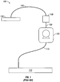
- FIG 1 illustrates a bulk ink delivery system 100 according to the prior art.
- the ink delivery system 100 includes a bulk ink reservoir 110, supply lines 115, 120, 140, a pump 125, a filter 130 and a block of print heads 135.
- ink is sucked from the ink reservoir 100 by the pump 125, delivered through the supply lines 115, 120, 140, filtered by the filter 130, and delivered to the block of print heads 135.
- sucking ink through the filter 130 creates air bubbles in the ink.
- the ink reservoir is emptied, air is sucked into the block of print heads 135.
- the invention introduces a primary ink system in fluid communication with a secondary ink system, wherein the primary ink system is configured to automatically bleed air from the system, so little or no air is mixed with the ink once it reaches the secondary ink system.
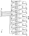
- FIG. 2A illustrates schematic representation of a bulk ink delivery system 200 according to some embodiments of the invention.
- the bulk ink delivery system 200 includes a plurality of bulk ink containers 201a, 201b, 201c, 201d, 201e, 201f, 201g, and 201n.
- ink from the containers is delivered to the print head carriage 299 via a plurality of primary ink delivery modules 202a, 202b, 202c, 202d, 202e, 202f, 202g, and 202n.
- the ink delivery system 200 comprises ink containers containing ink defining the CYMK color space, or a variant of the CYMK color space, i.e. light yellow, cyan, light magenta, black, light black, magenta, light cyan, and yellow.
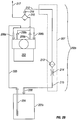
- Figure 2B illustrates schematic detail representation of an individual bulk ink container 201x and an individual primary ink delivery module 202x according to some embodiments of the invention.
- the ink container 201x is in fluid communication with a pump 203 via a draw tube 204, supply line 205, and pump inlet valves 206a, 206b.
- the ink container 201x is in fluid communication with an air bleeder return assembly 207 (boxed with dotted lines) via air pressure intake line 208.
- fluid comprising a mixture of ink and air
- the air bleeder return assembly 207 comprises a supply line 212, secondary filter 213, flow restrictor orifice 214, and supply line 215.
- the primary filter 210 comprises a filter with a bleed valve 216.
- the filter is located in-line, before the pump and the bleed valve is capped, blocked with a bleed screw, or nonexistant.
- the primary filter 210 is placed after the pump 203 and the bleed valve 216 feeds the supply line 212 of the air bleeder return assembly 207.
- the air bleeder return assembly 207 includes a flow restrictor orifice 214 which connects the bleed valve 216 back to the bulk ink container 201x.
- the flow restrictor orifice 214 is precisely-sized to allow all the air to flow quickly, but to create enough pressure for the air free ink to be pumped through the primary filter 210 and to the print head carriage 299 via supply line 217.
- Positioning the primary filter 210 and the air bleeder return assembly 207 in this fashion allows clean ink, free from air bubbles to be pumped to the carriage 299, minimizing jet dropouts, ink misdirection, and other defects that affect print quality. Additionally, this setup provides the added advantage of the ability to run the bulk bags dry without ingesting large quantities of air to the ink delivery system.
- the secondary filter 213 comprises a screen filter.
- Figure 2C illustrates an isometric representation of a printer system 298 comprising a plurality of primary ink delivery modules 202a, 202b, 202c, 202d, 202e, 202f, 202g, and 202n for delivering ink to printer 296 according to some embodiments of the invention.
- the printer system 298 includes a plurality of bulk ink containers 201a, 201b, 201c, 201d, 201e, 201f, 201g, and 201n configured for delivering ink to a print head carriage 299 of the printer 296.
- the printer 296 comprises a piezoelectric printer with a print head carriage 299 containing ink heads defining the CYMK color space, or a variant of the CYMK color space, i.e. light yellow, cyan, light magenta, black, light black, magenta, light cyan, and yellow.
- FIG. 3 illustrates an exploded view of an air bleeder return assembly 307 according to some embodiments of the invention.
- the air bleeder return assembly 307 comprises a flow restrictor orifice 314 coupled with ink tubes 301, 302.
- Ink tube 301 terminates with a quick coupling 303 chosen to couple with the supply line (shown in Fig. 2B ) and bleed valve (shown in Fig. 2B ) from the primary filter (shown in Fig. 2B ).
- Ink tube 302 is coupled with a filter 305 via a quick coupling 304.
- the filter 305 is coupled with another ink tube 307 via another quick coupling 306.
- Ink tube 307 terminates with a fitting 308 to couple with a bulk ink container.
- the flow restrictor orifice 214 is precisely-sized to allow all the air to flow quickly, but to create enough pressure for the air free ink to be pumped through the primary filter 210 and to the print head carriage 299.
- Another aspect of the invention involves a variable-sized orifice and a controller for controlling the orifice size, thereby providing an operator with the ability to tune ink flow rates and ink viscosity while still ensuring proper air removal.
- Figure 4 illustrates schematic detail representation of a ink delivery system 400 comprising a bulk ink container 401, a primary ink delivery module 402 with variable-sized orifice, and a controller 403 according to some embodiments of the invention.
- the ink container 401 is in fluid communication with a pump 403 via a draw tube 404, a supply line 405, and pump inlet valves 406a, 406b.
- the ink container 401 is in fluid communication with a variable-sized orifice air bleeder return assembly 407 (boxed with dotted lines) via air pressure intake line 408.
- variable-sized orifice air bleeder return assembly 407 comprises a supply line 412, secondary filter 413, a variable-sized orifice flow restrictor 414, and a supply line 415.
- the variable-sized orifice flow restrictor 414 is coupled with a controller 420.
- the controller 420 comprises a processor 421 operatively coupled with a memory 422, wherein the processor 421 is configured for controlling the orifice size of the variable-sized orifice flow restrictor 414.
- the processor 421 is configured to automatically gather data from the ink delivery system 400 via flow meters, O 2 sensors, and other sensors commonly used for fluid metering and analysis by those having ordinary skill in the art.
- the processor 421 is coupled with a display 423 having a graphical user interface. According to these embodiments, a human operator controls the orifice size of the variable-sized orifice flow restrictor 414 to precisely control fluid attributes.
- FIG. 5 illustrates a method 500 for operating a bulk ink delivery system and for controlling a variable-sized orifice flow restrictor to ensure proper air removal according to some embodiments of the invention.
- the method 500 begins by coupling a bulk ink container to a primary ink delivery system 501.
- a controller monitors fluid attributes in the ink container 502 that affect flow rate.
- the controller determines an ink flow rate necessary to bleed air from the primary ink delivery system via a bleed valve of a primary filter 503.
- the controller varies the size of an orifice in a variable-sized orifice flow restrictor, thereby ensuring the determined flow rate 504.
- ink is delivered through the primary filter to one or more print heads 505.
- Figure 6 is a block schematic diagram of a machine in the exemplary form of a computer system 600 within which a set of instructions may be programmed to cause the machine to execute the logic steps of the invention.
- the machine may comprise a network router, a network switch, a network bridge, personal digital assistant (PDA), a cellular telephone, a Web appliance or any machine capable of executing a sequence of instructions that specify actions to be taken by that machine.
- PDA personal digital assistant
- the computer system 600 includes a processor 602, a main memory 604 and a static memory 606, which communicate with each other via a bus 608.
- the computer system 600 may further include a display unit 610, for example, a liquid crystal display (LCD) or a cathode ray tube (CRT).
- the computer system 600 also includes an alphanumeric input device 612, for example, a keyboard; a cursor control device 614, for example, a mouse; a disk drive unit 616, a signal generation device 618, for example, a speaker, and a network interface device 620.
- the disk drive unit 616 includes a machine-readable medium 624 on which is stored a set of executable instructions, i.e. software, 626 embodying any one, or all, of the methodologies described herein below.
- the software 626 is also shown to reside, completely or at least partially, within the main memory 604 and/or within the processor 602.
- the software 626 may further be transmitted or received over a network 628, 630 by means of a network interface device 620.
- a different embodiment uses logic circuitry instead of computer-executed instructions to implement processing entities.
- this logic may be implemented by constructing an application-specific integrated circuit (ASIC) having thousands of tiny integrated transistors.
- ASIC application-specific integrated circuit
- Such an ASIC may be implemented with CMOS (complimentary metal oxide semiconductor), TTL (transistor-transistor logic), VLSI (very large systems integration), or another suitable construction.
- DSP digital signal processing chip
- FPGA field programmable gate array
- PLA programmable logic array
- PLD programmable logic device
- a machine-readable medium includes any mechanism for storing or transmitting information in a form readable by a machine, e.g. a computer.
- a machine readable medium includes read-only memory (ROM); random access memory (RAM); magnetic disk storage media; optical storage media; flash memory devices; electrical, optical, acoustical or other form of propagated signals, for example, carrier waves, infrared signals, digital signals, etc.; or any other type of media suitable for storing or transmitting information.
Landscapes
- Ink Jet (AREA)
Description
- The invention relates to the field of inkjet printing. More specifically the invention relates to systems for automatically bleeding air from an ink delivery system.
- Inkjet printing involves depositing droplets of liquid ink onto a printing medium from one or more printer heads. The printer heads are coupled with a container containing ink. Ink is ejected from one or more nozzles of the print heads when a piezoelectric crystal in the print head is actuated. The piezoelectric crystal generates a pulse in the ink so that the ink expels through the nozzle as a droplet. To create the image, a carriage which holds one or more print heads scans or traverses across the printing medium, while the print heads deposit ink as the printing medium moves.
- Small desktop inkjet printers are common consumer electronic products. Indeed, many consumer and business printing needs may be met by small desktop inkjet printing systems because of the relatively small amount of ink needed for common print jobs. However, some printing applications require much larger amounts of ink. For instance, large format printing is performed to create signs, banners, museum displays, sails, bus boards and the like. These types of applications require large throughput printers and require a much larger quantity of ink.
- Ink cartridges are typically sold with replaceable ink reservoirs. Most commonly, these ink reservoirs are individually packaged and sold over the counter. However, common inkjet reservoirs contain far less ink than is required for large format printing. Currently, replacement reservoirs are not available in volumes greater than approximately five liters. Furthermore, the overhead cost associated with individually manufacturing, packaging and shipping small, individual replacement reservoirs is burdensome given that they must be replaced frequently to achieve large format printing. Accordingly, many print applications benefit from bulk ink supply systems.
- Typical bulk ink supply systems for inkjet printers involve supplying the print head of the inkjet printer with ink from a bulk reservoir remote from the print head via ink lines. Some approaches in bulk ink supply involve a gravity feed, capillary feed, siphons or other mechanisms, instead of active electrical/mechanical devices, to transfer ink to the printing head. However, gravity feed ink delivery systems have inherent limitations, as their use often results in ink starvation or flooding at the printing head. These phenomena occur because the level of the ink immediately adjacent to the printing head is insufficiently maintained either due to limitations of the feed system or the need to manually adjust and replenish the ink reserves.
- Accordingly, there is a need for a system of using bulk ink reservoirs to supply an inkjet system in which air is not mixed with the ink that is pumped to the print heads which is reliable and commercially feasible.
-
US-A-4 658 268 discloses a hydraulic system for an ink supply system for an ink jet printer. A first pump conveys ink under pressure from a reservoir to a work head and a gear pump returns unused liquid from a collector at the work head to the reservoir. A bleed line connects an outlet from the first pump to an inlet to the gear pump. Accordingly, there is a flow of liquid via the bleed line such that the gear pump applies sufficient suction to the collector to draw air or a mixture of air and unused liquid therefrom. The flow is also sufficient to ensure adequate lubrication of the gear pump. - In view of the foregoing, the invention provides systems and methods of automatically bleeding air from a primary ink delivery system, so little or no air is mixed with the ink once it reaches a secondary ink system containing print heads.
- The invention provides a printing system according to
claim 1 and a method of preventing gas from entering a print head carriage according to claim 2. - Some embodiments of the invention involve a bulk ink delivery system having a plurality of bulk ink containers coupled with primary ink delivery modules for delivering ink from the containers is to the print head carriage. In some embodiments of the invention, the ink delivery system comprises ink containers containing ink defining the CYMK color space, or a variant of the CYMK color space, i.e. light yellow, cyan, light magenta, black, light black, magenta, light cyan, and yellow.
- The presently preferred embodiments of the invention involve an air bleeder return assembly with a flow restrictor orifice that is configured to remove air from ink pumped to the carriage of print heads, thereby minimizing jet dropouts. Additionally, this setup provides the added advantage of the ability to run the bulk bags dry without ingesting large quantities of air to the ink delivery system.
- Accordingly, there is a need for a system of using bulk ink reservoirs to supply an inkjet system in which air is not mixed with the ink that is pumped to the print heads which is reliable and commercially feasible.
- In view of the foregoing, the invention provides systems and methods of automatically bleeding air from a primary ink delivery system, so little or no air is mixed with the ink once it reaches a secondary ink system containing print heads.
- Some embodiments of the invention involve a bulk ink delivery system having a plurality of bulk ink containers coupled with primary ink delivery modules for delivering ink from the containers is to the print head carriage. In some embodiments of the invention, the ink delivery system comprises ink containers containing ink defining the CYMK color space, or a variant of the CYMK color space, i.e. light yellow, cyan, light magenta, black, light black, magenta, light cyan, and yellow.
- The presently preferred embodiments of the invention involve an air bleeder return assembly with a flow restrictor orifice that is configured to remove air from ink pumped to the carriage of print heads, thereby minimizing jet dropouts. Additionally, this setup provides the added advantage of the ability to run the bulk bags dry without ingesting large quantities of air to the ink delivery system.
- According to these embodiments, a bleed component comprising a primary filter is placed after a pump and the bleed valve of the filter feeds the supply line of the air bleeder return assembly. The air bleeder return assembly includes a flow restrictor orifice that is precisely-sized to allow all the air to flow quickly, but to create enough pressure for the air free ink to be pumped through the primary filter and to the print head carriage.
- Some embodiments of the invention involve an air bleeder return assembly comprises a flow restrictor orifice coupled with ink tubes, quick couplings, at least one secondary filter, and other unique fittings to easily couple with a bulk ink container.
- Some embodiments of the invention involve a variable-sized orifice and a controller for controlling the orifice size, thereby providing an operator with the ability to tune ink flow rates and ink viscosity while still ensuring proper air removal. In some embodiments of the invention, the controller comprises a processor operatively coupled with a memory, wherein the processor is configured for controlling the orifice size of the variable-sized orifice flow restrictor.
- In some embodiments of the invention, the processor is configured to automatically gather data from the ink delivery system via flow meters, O2 sensors, and other sensors commonly used for fluid metering and analysis.
- In some other embodiments of the invention, the processor is coupled with a display having a graphical user interface such that a human operator controls the orifice size of the variable-sized orifice flow restrictor to precisely control fluid attributes.
- Some other embodiments of the invention involve a method for operating a bulk ink delivery system and for controlling a variable-sized orifice flow restrictor to ensure proper air removal according to some embodiments of the invention.
-
-
Figure 1 illustrates a bulk ink delivery system according to the prior art; -
Figure 2A illustrates schematic representation of an ink delivery system according to some embodiments of the invention; -
Figure 2B illustrates schematic detail representation of an individual bulk ink container and an individual primary ink delivery module according to some embodiments of the invention; -
Figure 2C illustrates an isometric representation of a printer system comprising a plurality of primary ink delivery modules for delivering ink to printer according to some embodiments of the invention; -
Figure 3 illustrates an exploded view of the air bleeder return assembly according to some embodiments of the invention; -
Figure 4 illustrates schematic detail representation of an individual bulk ink container and an individual primary ink delivery module with variable-sixed orifice according to some embodiments of the invention; -
Figure 5 illustrates a method for operating a bulk ink delivery system and for controlling a variable-sized orifice flow restrictor to ensure proper air removal according to some embodiments of the invention; and -
Figure 6 is a block schematic diagram of a machine in the exemplary form of a computer system within which a set of instructions may be programmed to cause the machine to execute the logic steps of the invention. - As explained above, previous approaches that utilize bulk ink reservoirs involve a pump configured to suck ink from the bulk reservoir through a filter to the print heads via supply lines.
Figure 1 illustrates a bulkink delivery system 100 according to the prior art. Theink delivery system 100 includes abulk ink reservoir 110,supply lines pump 125, afilter 130 and a block ofprint heads 135. According toFigure 1 , ink is sucked from theink reservoir 100 by thepump 125, delivered through thesupply lines filter 130, and delivered to the block of print heads 135. However, sucking ink through thefilter 130 creates air bubbles in the ink. Likewise, once the ink reservoir is emptied, air is sucked into the block of print heads 135. - The invention introduces a primary ink system in fluid communication with a secondary ink system, wherein the primary ink system is configured to automatically bleed air from the system, so little or no air is mixed with the ink once it reaches the secondary ink system.
-
Figure 2A illustrates schematic representation of a bulkink delivery system 200 according to some embodiments of the invention. The bulkink delivery system 200 includes a plurality ofbulk ink containers - According to
Figure 2A , ink from the containers is delivered to theprint head carriage 299 via a plurality of primaryink delivery modules - In the presently preferred embodiments of the invention, the
ink delivery system 200 comprises ink containers containing ink defining the CYMK color space, or a variant of the CYMK color space, i.e. light yellow, cyan, light magenta, black, light black, magenta, light cyan, and yellow. -
Figure 2B illustrates schematic detail representation of an individualbulk ink container 201x and an individual primaryink delivery module 202x according to some embodiments of the invention. - The
ink container 201x is in fluid communication with apump 203 via adraw tube 204,supply line 205, and pumpinlet valves ink container 201x is in fluid communication with an air bleeder return assembly 207 (boxed with dotted lines) via airpressure intake line 208. In operation, fluid, comprising a mixture of ink and air, is pumped out of thepump 203 viaoutlet valves bleeder return assembly 207. The airbleeder return assembly 207 comprises asupply line 212,secondary filter 213, flowrestrictor orifice 214, andsupply line 215. - The primary filter 210 comprises a filter with a
bleed valve 216. According to prior approaches, the filter is located in-line, before the pump and the bleed valve is capped, blocked with a bleed screw, or nonexistant. - However, according to the preferred embodiments of the invention, the primary filter 210 is placed after the
pump 203 and thebleed valve 216 feeds thesupply line 212 of the airbleeder return assembly 207. As explained above, the airbleeder return assembly 207 includes a flowrestrictor orifice 214 which connects thebleed valve 216 back to thebulk ink container 201x. - The flow
restrictor orifice 214 is precisely-sized to allow all the air to flow quickly, but to create enough pressure for the air free ink to be pumped through the primary filter 210 and to theprint head carriage 299 viasupply line 217. - Positioning the primary filter 210 and the air bleeder return assembly 207 in this fashion allows clean ink, free from air bubbles to be pumped to the
carriage 299, minimizing jet dropouts, ink misdirection, and other defects that affect print quality. Additionally, this setup provides the added advantage of the ability to run the bulk bags dry without ingesting large quantities of air to the ink delivery system. - Positioning the
bleed valve 216 and flowrestrictor orifice 214 on the up side of the primary filter 210 allows particulates through that could clog the flowrestrictor orifice 214; therefore, thesecondary filter 213 is placed prior to flowrestrictor orifice 214. In the presently preferred embodiments of the invention, thesecondary filter 213 comprises a screen filter. -
Figure 2C illustrates an isometric representation of aprinter system 298 comprising a plurality of primaryink delivery modules printer 296 according to some embodiments of the invention. - The
printer system 298 includes a plurality ofbulk ink containers print head carriage 299 of theprinter 296. In the presently preferred embodiments of the invention, theprinter 296 comprises a piezoelectric printer with aprint head carriage 299 containing ink heads defining the CYMK color space, or a variant of the CYMK color space, i.e. light yellow, cyan, light magenta, black, light black, magenta, light cyan, and yellow. -
Figure 3 illustrates an exploded view of an air bleeder return assembly 307 according to some embodiments of the invention. The airbleeder return assembly 307 comprises a flowrestrictor orifice 314 coupled withink tubes Ink tube 301 terminates with aquick coupling 303 chosen to couple with the supply line (shown inFig. 2B ) and bleed valve (shown inFig. 2B ) from the primary filter (shown inFig. 2B ).Ink tube 302 is coupled with afilter 305 via aquick coupling 304. Likewise, thefilter 305 is coupled with anotherink tube 307 via anotherquick coupling 306.Ink tube 307 terminates with a fitting 308 to couple with a bulk ink container. - As explained above in reference to
Figure 2B , the flowrestrictor orifice 214 is precisely-sized to allow all the air to flow quickly, but to create enough pressure for the air free ink to be pumped through the primary filter 210 and to theprint head carriage 299. - Another aspect of the invention involves a variable-sized orifice and a controller for controlling the orifice size, thereby providing an operator with the ability to tune ink flow rates and ink viscosity while still ensuring proper air removal.
-
Figure 4 illustrates schematic detail representation of a ink delivery system 400 comprising abulk ink container 401, a primary ink delivery module 402 with variable-sized orifice, and acontroller 403 according to some embodiments of the invention. - According to
Figure 4 , theink container 401 is in fluid communication with apump 403 via adraw tube 404, asupply line 405, and pumpinlet valves ink container 401 is in fluid communication with a variable-sized orifice air bleeder return assembly 407 (boxed with dotted lines) via airpressure intake line 408. - Additionally, a mixture of ink and air is pumped out of the
pump 403 viaoutlet valves bleeder return assembly 407. The variable-sized orifice airbleeder return assembly 407 comprises asupply line 412,secondary filter 413, a variable-sizedorifice flow restrictor 414, and asupply line 415. The variable-sizedorifice flow restrictor 414 is coupled with acontroller 420. - In the preferred embodiments of the invention, the
controller 420 comprises aprocessor 421 operatively coupled with amemory 422, wherein theprocessor 421 is configured for controlling the orifice size of the variable-sizedorifice flow restrictor 414. In some embodiments of the invention, theprocessor 421 is configured to automatically gather data from the ink delivery system 400 via flow meters, O2 sensors, and other sensors commonly used for fluid metering and analysis by those having ordinary skill in the art. - In some other embodiments of the invention, the
processor 421 is coupled with adisplay 423 having a graphical user interface. According to these embodiments, a human operator controls the orifice size of the variable-sized orifice flow restrictor 414 to precisely control fluid attributes. -
Figure 5 illustrates amethod 500 for operating a bulk ink delivery system and for controlling a variable-sized orifice flow restrictor to ensure proper air removal according to some embodiments of the invention. Themethod 500 begins by coupling a bulk ink container to a primaryink delivery system 501. Next, a controller monitors fluid attributes in theink container 502 that affect flow rate. The controller determines an ink flow rate necessary to bleed air from the primary ink delivery system via a bleed valve of aprimary filter 503. Next, the controller varies the size of an orifice in a variable-sized orifice flow restrictor, thereby ensuring thedetermined flow rate 504. Finally, ink is delivered through the primary filter to one or more print heads 505. -
Figure 6 is a block schematic diagram of a machine in the exemplary form of acomputer system 600 within which a set of instructions may be programmed to cause the machine to execute the logic steps of the invention. In alternative embodiments, the machine may comprise a network router, a network switch, a network bridge, personal digital assistant (PDA), a cellular telephone, a Web appliance or any machine capable of executing a sequence of instructions that specify actions to be taken by that machine. - The
computer system 600 includes aprocessor 602, amain memory 604 and a static memory 606, which communicate with each other via abus 608. Thecomputer system 600 may further include adisplay unit 610, for example, a liquid crystal display (LCD) or a cathode ray tube (CRT). Thecomputer system 600 also includes analphanumeric input device 612, for example, a keyboard; acursor control device 614, for example, a mouse; adisk drive unit 616, asignal generation device 618, for example, a speaker, and a network interface device 620. - The
disk drive unit 616 includes a machine-readable medium 624 on which is stored a set of executable instructions, i.e. software, 626 embodying any one, or all, of the methodologies described herein below. Thesoftware 626 is also shown to reside, completely or at least partially, within themain memory 604 and/or within theprocessor 602. Thesoftware 626 may further be transmitted or received over anetwork - In contrast to the
system 600 discussed above, a different embodiment uses logic circuitry instead of computer-executed instructions to implement processing entities. Depending upon the particular requirements of the application in the areas of speed, expense, tooling costs, and the like, this logic may be implemented by constructing an application-specific integrated circuit (ASIC) having thousands of tiny integrated transistors. Such an ASIC may be implemented with CMOS (complimentary metal oxide semiconductor), TTL (transistor-transistor logic), VLSI (very large systems integration), or another suitable construction. Other alternatives include a digital signal processing chip (DSP), discrete circuitry (such as resistors, capacitors, diodes, inductors, and transistors), field programmable gate array (FPGA), programmable logic array (PLA), programmable logic device (PLD), and the like. - It is to be understood that embodiments may be used as or to support software programs or software modules executed upon some form of processing core (such as the CPU of a computer) or otherwise implemented or realized upon or within a machine or computer readable medium. A machine-readable medium includes any mechanism for storing or transmitting information in a form readable by a machine, e.g. a computer. For example, a machine readable medium includes read-only memory (ROM); random access memory (RAM); magnetic disk storage media; optical storage media; flash memory devices; electrical, optical, acoustical or other form of propagated signals, for example, carrier waves, infrared signals, digital signals, etc.; or any other type of media suitable for storing or transmitting information.
Claims (6)
- A printing system (100; 298) comprising:an inkjet printer (296) comprising a plurality of print heads (135) for respectively jetting a plurality of color inks onto a recording medium;a plurality of bulk ink containers (201a-201n) storing liquid inks of various colors, wherein the totality of the various colors define a color model;a plurality of primary ink delivery modules (202a-202n) configured for individually delivering individually-colored inks to each of the plurality of print heads, wherein each of the primary ink delivery modules further comprise:a pump (203) configured to draw a fluid from an individual bulk ink container, wherein said fluid comprises ink and at least a portion of gas mixed with said ink;at least one pump outlet (209a, 209b) configured for pushing said fluid to a bleed component comprising a primary filter (210), a filter outlet, and a bleed valve (216) characterized byan air bleeder assembly (207) with a first terminal end coupled with said bleed valve via a supply line (212) and a second terminal end coupled with said bulk ink container, wherein said air bleeder assembly further comprises:a flow restrictor orifice (214) precisely-sized to allow said gas to flow back to said individual bulk ink container and to create enough pressure for gas-free ink to be pumped through the bleed component and to a print head via said pump outlet; anda secondary filter (213) positioned upstream from said flow restrictor orifice.
- A method of preventing gas from entering a print head carriage (299) comprising the steps of:coupling individual bulk containers from among a plurality of bulk ink containers (201a-201n) to individual print heads (135) in an inkjet printer carriage (299), wherein said individual bulk ink containers contain liquid inks of various colors, wherein the totality of the various colors define a color model;coupling individual ink delivery modules (202a-202n) with each of said individual bulk ink containers and with individual print heads in a print head carriage, further comprising:configuring each individual ink delivery module (202a-202n) with a pump (203) configured to draw a fluid from each individual bulk ink container, wherein said fluid comprises ink and at least a portion of gas mixed with said ink;configuring each individual ink delivery module with a pump outlet (209a, 209b) configured for pushing said fluid to a bleed component comprising a primary filter (210), a filter outlet, and a bleed valve (216); characterized byconfiguring each individual ink delivery module with an air bleeder assembly (207) having a first terminal end coupled with said bleed valve via a supply line (212) and a second terminal end coupled with said bulk ink container;configuring said air bleeder assembly with a flow restrictor orifice (214) for allowing said gas to flow back to said individual bulk ink container, the flow restrictor orifice (214) being configured to create enough pressure for gas-free ink to be pumped through the bleed component and to a print head via said pump outlet;wherein a secondary filter (213) is positioned upstream from said flow restrictor orifice;wherein each individual ink delivery module individually delivers individually-colored inks to each of the plurality of print heads.
- The method of Claim 2, further comprising precisely choosing the size of said flow restrictor orifice (214) to allow said gas to flow back to said individual bulk ink container (201a-201n) and to create enough pressure for gas-free ink to be pumped through said primary filter (210) for an ink having a particular viscosity.
- The method of Claim 2, wherein the step of configuring said air bleeder assembly (207) further comprises coupling a variable flow restrictor orifice (414) with said air bleeder assembly.
- The method of Claim 4, further comprising:coupling a controller (403) to said variable flow restrictor orifice (414), wherein said controller comprises a processor (421) and memory (422).
- The method of Claim 4, further comprising:coupling at least one ink attribute sensor with at least one individual ink delivery module;coupling said at least one ink attribute sensor with said controller (420);configuring said processor (421) to automatically control the flow through said variable flow restrictor orifice (414) based on ink attributes sensed by said at least one ink attribute sensor.
Applications Claiming Priority (2)
| Application Number | Priority Date | Filing Date | Title |
|---|---|---|---|
| US13/301,477 US8616691B2 (en) | 2011-11-21 | 2011-11-21 | Gas removal from a fluid delivery system |
| PCT/US2012/066235 WO2013078293A1 (en) | 2011-11-21 | 2012-11-21 | Gas removal from a fluid delivery system |
Publications (3)
| Publication Number | Publication Date |
|---|---|
| EP2783188A1 EP2783188A1 (en) | 2014-10-01 |
| EP2783188A4 EP2783188A4 (en) | 2017-03-08 |
| EP2783188B1 true EP2783188B1 (en) | 2019-02-06 |
Family
ID=48426402
Family Applications (1)
| Application Number | Title | Priority Date | Filing Date |
|---|---|---|---|
| EP12851109.4A Not-in-force EP2783188B1 (en) | 2011-11-21 | 2012-11-21 | Gas removal from a fluid delivery system |
Country Status (5)
| Country | Link |
|---|---|
| US (2) | US8616691B2 (en) |
| EP (1) | EP2783188B1 (en) |
| CN (1) | CN104040297B (en) |
| ES (1) | ES2719799T3 (en) |
| WO (1) | WO2013078293A1 (en) |
Families Citing this family (5)
| Publication number | Priority date | Publication date | Assignee | Title |
|---|---|---|---|---|
| US8616691B2 (en) * | 2011-11-21 | 2013-12-31 | Electronics For Imaging, Inc. | Gas removal from a fluid delivery system |
| US20140352822A1 (en) * | 2013-05-31 | 2014-12-04 | Eaton Corporation | Air bleed valve float arrangement with restrictor |
| US11123977B2 (en) | 2018-01-08 | 2021-09-21 | Hewlett-Packard Development Company, L.P. | Displacing a substance |
| US10974517B2 (en) * | 2018-10-16 | 2021-04-13 | Electronics For Imaging, Inc. | High stability ink delivery systems, and associated print systems and methods |
| EP3996900B1 (en) * | 2019-07-08 | 2024-12-11 | Hewlett-Packard Development Company, L.P. | Printing agent transfer for 2d and 3d printers |
Family Cites Families (13)
| Publication number | Priority date | Publication date | Assignee | Title |
|---|---|---|---|---|
| GB8328000D0 (en) | 1983-10-19 | 1983-11-23 | Domino Printing Sciences Ltd | Hydraulic systems |
| US4575738A (en) | 1984-07-20 | 1986-03-11 | Tektronix, Inc. | Ink jet printing apparatus having an ink pressure transient suppressor system |
| DE69524651T2 (en) | 1994-01-27 | 2002-06-13 | Hewlett-Packard Co.(A Delaware Corporation), Palo Alto | Printing system and method |
| US6318851B1 (en) | 1999-04-07 | 2001-11-20 | Hewlett-Packard Company | Method and system for purging air from a print mechanism |
| US6572214B2 (en) | 2001-03-09 | 2003-06-03 | Hewlett-Packard Development Company, L.P. | Inkjet printing systems using filter fluid interconnects for pigmented inks |
| US6637860B1 (en) | 2002-05-13 | 2003-10-28 | Creo Srl | High throughput inkjet printer with provision for spot color printing |
| CN100431842C (en) * | 2003-02-04 | 2008-11-12 | 兄弟工业株式会社 | Bubble removal in an inkjet printer |
| JP4003743B2 (en) * | 2003-12-11 | 2007-11-07 | ブラザー工業株式会社 | Inkjet printer |
| US7625080B2 (en) * | 2004-06-18 | 2009-12-01 | Hewlett-Packard Development Company, L.P. | Air management in a fluid ejection device |
| GB0618620D0 (en) | 2006-09-22 | 2006-11-01 | The Technology Partnership Plc | Ink supply system |
| JP5151828B2 (en) * | 2008-09-04 | 2013-02-27 | コニカミノルタIj株式会社 | Inkjet printer |
| US8348406B2 (en) * | 2010-07-30 | 2013-01-08 | Xerox Corporation | Liquid ink delivery system including a flow restrictor that resists air bubble formation in a liquid ink reservoir |
| US8616691B2 (en) * | 2011-11-21 | 2013-12-31 | Electronics For Imaging, Inc. | Gas removal from a fluid delivery system |
-
2011
- 2011-11-21 US US13/301,477 patent/US8616691B2/en active Active
-
2012
- 2012-11-21 CN CN201280066498.0A patent/CN104040297B/en not_active Expired - Fee Related
- 2012-11-21 ES ES12851109T patent/ES2719799T3/en active Active
- 2012-11-21 WO PCT/US2012/066235 patent/WO2013078293A1/en not_active Ceased
- 2012-11-21 EP EP12851109.4A patent/EP2783188B1/en not_active Not-in-force
-
2013
- 2013-11-11 US US14/076,990 patent/US8807727B2/en active Active
Non-Patent Citations (1)
| Title |
|---|
| None * |
Also Published As
| Publication number | Publication date |
|---|---|
| CN104040297B (en) | 2017-05-03 |
| WO2013078293A1 (en) | 2013-05-30 |
| EP2783188A1 (en) | 2014-10-01 |
| US20140063153A1 (en) | 2014-03-06 |
| US20130127936A1 (en) | 2013-05-23 |
| EP2783188A4 (en) | 2017-03-08 |
| US8616691B2 (en) | 2013-12-31 |
| CN104040297A (en) | 2014-09-10 |
| ES2719799T3 (en) | 2019-07-16 |
| US8807727B2 (en) | 2014-08-19 |
Similar Documents
| Publication | Publication Date | Title |
|---|---|---|
| CN1960879B (en) | Ink supply apparatus, recording apparatus, ink supply method, and recording method | |
| US8807727B2 (en) | Gas removal from a fluid delivery system | |
| CN100526076C (en) | Image forming apparatus, printer complex system and medium conveying device for the same, information processing device for supplying image data to the image forming apparatus, and image forming system and image forming method provided with the same | |
| CN112440564B (en) | Printing units and printing systems | |
| JP5272947B2 (en) | Image forming apparatus | |
| CN1324303A (en) | Ink delivery pressure control | |
| CN113195233B (en) | High stability ink delivery system and related printing systems and methods | |
| JP2010194973A (en) | Image forming apparatus | |
| JP5593924B2 (en) | Printing control apparatus, printing apparatus, and printing control method in printing apparatus | |
| CN113650417B (en) | Liquid ejection device and dispensing system for liquid ejection head | |
| JP2017530884A (en) | Printhead assembly and inkjet printer | |
| JP6488897B2 (en) | Liquid ejecting apparatus and control method thereof | |
| US8491082B2 (en) | Recording apparatus and recording method of recording apparatus | |
| CN102673169B (en) | Recording apparatus and recording method | |
| JP4819586B2 (en) | Liquid ejection mechanism and image forming apparatus | |
| JP5663971B2 (en) | Fluid ejection device | |
| JP2007130897A (en) | Liquid ejector | |
| KR20100015687A (en) | Handheld and/or mountable fluid-ejection device having tip-extension assembly and/or tubings | |
| CN121536097A (en) | A dual-head inkjet printer | |
| US20240100823A1 (en) | Liquid ejecting apparatus and method for controlling liquid ejecting apparatus | |
| US11440330B2 (en) | Liquid delivery in an inkjet type dispenser | |
| JP5764871B2 (en) | Fluid ejection device | |
| EP4069517B1 (en) | Method and system for priming dry printheads | |
| JP5061513B2 (en) | Inkjet spacer arrangement device and inkjet spacer arrangement method | |
| JP2023114080A (en) | Idle discharge method of liquid discharge device |
Legal Events
| Date | Code | Title | Description |
|---|---|---|---|
| PUAI | Public reference made under article 153(3) epc to a published international application that has entered the european phase |
Free format text: ORIGINAL CODE: 0009012 |
|
| 17P | Request for examination filed |
Effective date: 20140521 |
|
| AK | Designated contracting states |
Kind code of ref document: A1 Designated state(s): AL AT BE BG CH CY CZ DE DK EE ES FI FR GB GR HR HU IE IS IT LI LT LU LV MC MK MT NL NO PL PT RO RS SE SI SK SM TR |
|
| DAX | Request for extension of the european patent (deleted) | ||
| REG | Reference to a national code |
Ref country code: DE Ref legal event code: R079 Ref document number: 602012056546 Country of ref document: DE Free format text: PREVIOUS MAIN CLASS: G01D0009000000 Ipc: B41J0002175000 |
|
| RA4 | Supplementary search report drawn up and despatched (corrected) |
Effective date: 20170203 |
|
| RIC1 | Information provided on ipc code assigned before grant |
Ipc: B41J 2/055 20060101ALI20170130BHEP Ipc: B41J 2/175 20060101AFI20170130BHEP Ipc: B41J 2/19 20060101ALI20170130BHEP |
|
| GRAP | Despatch of communication of intention to grant a patent |
Free format text: ORIGINAL CODE: EPIDOSNIGR1 |
|
| STAA | Information on the status of an ep patent application or granted ep patent |
Free format text: STATUS: GRANT OF PATENT IS INTENDED |
|
| INTG | Intention to grant announced |
Effective date: 20180815 |
|
| GRAS | Grant fee paid |
Free format text: ORIGINAL CODE: EPIDOSNIGR3 |
|
| GRAA | (expected) grant |
Free format text: ORIGINAL CODE: 0009210 |
|
| STAA | Information on the status of an ep patent application or granted ep patent |
Free format text: STATUS: THE PATENT HAS BEEN GRANTED |
|
| AK | Designated contracting states |
Kind code of ref document: B1 Designated state(s): AL AT BE BG CH CY CZ DE DK EE ES FI FR GB GR HR HU IE IS IT LI LT LU LV MC MK MT NL NO PL PT RO RS SE SI SK SM TR |
|
| REG | Reference to a national code |
Ref country code: GB Ref legal event code: FG4D |
|
| REG | Reference to a national code |
Ref country code: CH Ref legal event code: EP Ref country code: AT Ref legal event code: REF Ref document number: 1094638 Country of ref document: AT Kind code of ref document: T Effective date: 20190215 |
|
| REG | Reference to a national code |
Ref country code: IE Ref legal event code: FG4D |
|
| REG | Reference to a national code |
Ref country code: DE Ref legal event code: R096 Ref document number: 602012056546 Country of ref document: DE |
|
| REG | Reference to a national code |
Ref country code: NL Ref legal event code: MP Effective date: 20190206 |
|
| REG | Reference to a national code |
Ref country code: LT Ref legal event code: MG4D |
|
| REG | Reference to a national code |
Ref country code: ES Ref legal event code: FG2A Ref document number: 2719799 Country of ref document: ES Kind code of ref document: T3 Effective date: 20190716 |
|
| PG25 | Lapsed in a contracting state [announced via postgrant information from national office to epo] |
Ref country code: NO Free format text: LAPSE BECAUSE OF FAILURE TO SUBMIT A TRANSLATION OF THE DESCRIPTION OR TO PAY THE FEE WITHIN THE PRESCRIBED TIME-LIMIT Effective date: 20190506 Ref country code: FI Free format text: LAPSE BECAUSE OF FAILURE TO SUBMIT A TRANSLATION OF THE DESCRIPTION OR TO PAY THE FEE WITHIN THE PRESCRIBED TIME-LIMIT Effective date: 20190206 Ref country code: NL Free format text: LAPSE BECAUSE OF FAILURE TO SUBMIT A TRANSLATION OF THE DESCRIPTION OR TO PAY THE FEE WITHIN THE PRESCRIBED TIME-LIMIT Effective date: 20190206 Ref country code: LT Free format text: LAPSE BECAUSE OF FAILURE TO SUBMIT A TRANSLATION OF THE DESCRIPTION OR TO PAY THE FEE WITHIN THE PRESCRIBED TIME-LIMIT Effective date: 20190206 Ref country code: PT Free format text: LAPSE BECAUSE OF FAILURE TO SUBMIT A TRANSLATION OF THE DESCRIPTION OR TO PAY THE FEE WITHIN THE PRESCRIBED TIME-LIMIT Effective date: 20190606 Ref country code: SE Free format text: LAPSE BECAUSE OF FAILURE TO SUBMIT A TRANSLATION OF THE DESCRIPTION OR TO PAY THE FEE WITHIN THE PRESCRIBED TIME-LIMIT Effective date: 20190206 |
|
| REG | Reference to a national code |
Ref country code: AT Ref legal event code: MK05 Ref document number: 1094638 Country of ref document: AT Kind code of ref document: T Effective date: 20190206 |
|
| PG25 | Lapsed in a contracting state [announced via postgrant information from national office to epo] |
Ref country code: LV Free format text: LAPSE BECAUSE OF FAILURE TO SUBMIT A TRANSLATION OF THE DESCRIPTION OR TO PAY THE FEE WITHIN THE PRESCRIBED TIME-LIMIT Effective date: 20190206 Ref country code: RS Free format text: LAPSE BECAUSE OF FAILURE TO SUBMIT A TRANSLATION OF THE DESCRIPTION OR TO PAY THE FEE WITHIN THE PRESCRIBED TIME-LIMIT Effective date: 20190206 Ref country code: BG Free format text: LAPSE BECAUSE OF FAILURE TO SUBMIT A TRANSLATION OF THE DESCRIPTION OR TO PAY THE FEE WITHIN THE PRESCRIBED TIME-LIMIT Effective date: 20190506 Ref country code: GR Free format text: LAPSE BECAUSE OF FAILURE TO SUBMIT A TRANSLATION OF THE DESCRIPTION OR TO PAY THE FEE WITHIN THE PRESCRIBED TIME-LIMIT Effective date: 20190507 Ref country code: IS Free format text: LAPSE BECAUSE OF FAILURE TO SUBMIT A TRANSLATION OF THE DESCRIPTION OR TO PAY THE FEE WITHIN THE PRESCRIBED TIME-LIMIT Effective date: 20190606 Ref country code: HR Free format text: LAPSE BECAUSE OF FAILURE TO SUBMIT A TRANSLATION OF THE DESCRIPTION OR TO PAY THE FEE WITHIN THE PRESCRIBED TIME-LIMIT Effective date: 20190206 |
|
| PG25 | Lapsed in a contracting state [announced via postgrant information from national office to epo] |
Ref country code: DK Free format text: LAPSE BECAUSE OF FAILURE TO SUBMIT A TRANSLATION OF THE DESCRIPTION OR TO PAY THE FEE WITHIN THE PRESCRIBED TIME-LIMIT Effective date: 20190206 Ref country code: EE Free format text: LAPSE BECAUSE OF FAILURE TO SUBMIT A TRANSLATION OF THE DESCRIPTION OR TO PAY THE FEE WITHIN THE PRESCRIBED TIME-LIMIT Effective date: 20190206 Ref country code: SK Free format text: LAPSE BECAUSE OF FAILURE TO SUBMIT A TRANSLATION OF THE DESCRIPTION OR TO PAY THE FEE WITHIN THE PRESCRIBED TIME-LIMIT Effective date: 20190206 Ref country code: AL Free format text: LAPSE BECAUSE OF FAILURE TO SUBMIT A TRANSLATION OF THE DESCRIPTION OR TO PAY THE FEE WITHIN THE PRESCRIBED TIME-LIMIT Effective date: 20190206 Ref country code: IT Free format text: LAPSE BECAUSE OF FAILURE TO SUBMIT A TRANSLATION OF THE DESCRIPTION OR TO PAY THE FEE WITHIN THE PRESCRIBED TIME-LIMIT Effective date: 20190206 Ref country code: CZ Free format text: LAPSE BECAUSE OF FAILURE TO SUBMIT A TRANSLATION OF THE DESCRIPTION OR TO PAY THE FEE WITHIN THE PRESCRIBED TIME-LIMIT Effective date: 20190206 Ref country code: RO Free format text: LAPSE BECAUSE OF FAILURE TO SUBMIT A TRANSLATION OF THE DESCRIPTION OR TO PAY THE FEE WITHIN THE PRESCRIBED TIME-LIMIT Effective date: 20190206 |
|
| REG | Reference to a national code |
Ref country code: DE Ref legal event code: R097 Ref document number: 602012056546 Country of ref document: DE |
|
| PG25 | Lapsed in a contracting state [announced via postgrant information from national office to epo] |
Ref country code: SM Free format text: LAPSE BECAUSE OF FAILURE TO SUBMIT A TRANSLATION OF THE DESCRIPTION OR TO PAY THE FEE WITHIN THE PRESCRIBED TIME-LIMIT Effective date: 20190206 Ref country code: PL Free format text: LAPSE BECAUSE OF FAILURE TO SUBMIT A TRANSLATION OF THE DESCRIPTION OR TO PAY THE FEE WITHIN THE PRESCRIBED TIME-LIMIT Effective date: 20190206 |
|
| PLBE | No opposition filed within time limit |
Free format text: ORIGINAL CODE: 0009261 |
|
| STAA | Information on the status of an ep patent application or granted ep patent |
Free format text: STATUS: NO OPPOSITION FILED WITHIN TIME LIMIT |
|
| PG25 | Lapsed in a contracting state [announced via postgrant information from national office to epo] |
Ref country code: AT Free format text: LAPSE BECAUSE OF FAILURE TO SUBMIT A TRANSLATION OF THE DESCRIPTION OR TO PAY THE FEE WITHIN THE PRESCRIBED TIME-LIMIT Effective date: 20190206 |
|
| 26N | No opposition filed |
Effective date: 20191107 |
|
| PG25 | Lapsed in a contracting state [announced via postgrant information from national office to epo] |
Ref country code: SI Free format text: LAPSE BECAUSE OF FAILURE TO SUBMIT A TRANSLATION OF THE DESCRIPTION OR TO PAY THE FEE WITHIN THE PRESCRIBED TIME-LIMIT Effective date: 20190206 |
|
| PG25 | Lapsed in a contracting state [announced via postgrant information from national office to epo] |
Ref country code: TR Free format text: LAPSE BECAUSE OF FAILURE TO SUBMIT A TRANSLATION OF THE DESCRIPTION OR TO PAY THE FEE WITHIN THE PRESCRIBED TIME-LIMIT Effective date: 20190206 |
|
| REG | Reference to a national code |
Ref country code: CH Ref legal event code: PL |
|
| PG25 | Lapsed in a contracting state [announced via postgrant information from national office to epo] |
Ref country code: CH Free format text: LAPSE BECAUSE OF NON-PAYMENT OF DUE FEES Effective date: 20191130 Ref country code: LI Free format text: LAPSE BECAUSE OF NON-PAYMENT OF DUE FEES Effective date: 20191130 Ref country code: LU Free format text: LAPSE BECAUSE OF NON-PAYMENT OF DUE FEES Effective date: 20191121 Ref country code: MC Free format text: LAPSE BECAUSE OF FAILURE TO SUBMIT A TRANSLATION OF THE DESCRIPTION OR TO PAY THE FEE WITHIN THE PRESCRIBED TIME-LIMIT Effective date: 20190206 |
|
| REG | Reference to a national code |
Ref country code: BE Ref legal event code: MM Effective date: 20191130 |
|
| PG25 | Lapsed in a contracting state [announced via postgrant information from national office to epo] |
Ref country code: IE Free format text: LAPSE BECAUSE OF NON-PAYMENT OF DUE FEES Effective date: 20191121 |
|
| PG25 | Lapsed in a contracting state [announced via postgrant information from national office to epo] |
Ref country code: BE Free format text: LAPSE BECAUSE OF NON-PAYMENT OF DUE FEES Effective date: 20191130 |
|
| PG25 | Lapsed in a contracting state [announced via postgrant information from national office to epo] |
Ref country code: CY Free format text: LAPSE BECAUSE OF FAILURE TO SUBMIT A TRANSLATION OF THE DESCRIPTION OR TO PAY THE FEE WITHIN THE PRESCRIBED TIME-LIMIT Effective date: 20190206 |
|
| PG25 | Lapsed in a contracting state [announced via postgrant information from national office to epo] |
Ref country code: MT Free format text: LAPSE BECAUSE OF FAILURE TO SUBMIT A TRANSLATION OF THE DESCRIPTION OR TO PAY THE FEE WITHIN THE PRESCRIBED TIME-LIMIT Effective date: 20190206 Ref country code: HU Free format text: LAPSE BECAUSE OF FAILURE TO SUBMIT A TRANSLATION OF THE DESCRIPTION OR TO PAY THE FEE WITHIN THE PRESCRIBED TIME-LIMIT; INVALID AB INITIO Effective date: 20121121 |
|
| REG | Reference to a national code |
Ref country code: DE Ref legal event code: R081 Ref document number: 602012056546 Country of ref document: DE Owner name: ELECTRONICS FOR IMAGING, INC., FREMONT, US Free format text: FORMER OWNER: ELECTRONICS FOR IMAGING, INC., FOSTER CITY, CALIF., US |
|
| PG25 | Lapsed in a contracting state [announced via postgrant information from national office to epo] |
Ref country code: MK Free format text: LAPSE BECAUSE OF FAILURE TO SUBMIT A TRANSLATION OF THE DESCRIPTION OR TO PAY THE FEE WITHIN THE PRESCRIBED TIME-LIMIT Effective date: 20190206 |
|
| P01 | Opt-out of the competence of the unified patent court (upc) registered |
Effective date: 20230526 |
|
| PGFP | Annual fee paid to national office [announced via postgrant information from national office to epo] |
Ref country code: GB Payment date: 20230928 Year of fee payment: 12 |
|
| PGFP | Annual fee paid to national office [announced via postgrant information from national office to epo] |
Ref country code: FR Payment date: 20230929 Year of fee payment: 12 |
|
| PGFP | Annual fee paid to national office [announced via postgrant information from national office to epo] |
Ref country code: ES Payment date: 20231207 Year of fee payment: 12 |
|
| PGFP | Annual fee paid to national office [announced via postgrant information from national office to epo] |
Ref country code: DE Payment date: 20230926 Year of fee payment: 12 |
|
| REG | Reference to a national code |
Ref country code: DE Ref legal event code: R119 Ref document number: 602012056546 Country of ref document: DE |
|
| GBPC | Gb: european patent ceased through non-payment of renewal fee |
Effective date: 20241121 |
|
| PG25 | Lapsed in a contracting state [announced via postgrant information from national office to epo] |
Ref country code: DE Free format text: LAPSE BECAUSE OF NON-PAYMENT OF DUE FEES Effective date: 20250603 |
|
| PG25 | Lapsed in a contracting state [announced via postgrant information from national office to epo] |
Ref country code: GB Free format text: LAPSE BECAUSE OF NON-PAYMENT OF DUE FEES Effective date: 20241121 |
|
| PG25 | Lapsed in a contracting state [announced via postgrant information from national office to epo] |
Ref country code: FR Free format text: LAPSE BECAUSE OF NON-PAYMENT OF DUE FEES Effective date: 20241130 |
|
| REG | Reference to a national code |
Ref country code: ES Ref legal event code: FD2A Effective date: 20260107 |
|
| PG25 | Lapsed in a contracting state [announced via postgrant information from national office to epo] |
Ref country code: ES Free format text: LAPSE BECAUSE OF NON-PAYMENT OF DUE FEES Effective date: 20241122 |