EP2783080B1 - Arrangement for fitting an exhaust cleaning unit in an exhaust passage - Google Patents
Arrangement for fitting an exhaust cleaning unit in an exhaust passage Download PDFInfo
- Publication number
- EP2783080B1 EP2783080B1 EP12852299.2A EP12852299A EP2783080B1 EP 2783080 B1 EP2783080 B1 EP 2783080B1 EP 12852299 A EP12852299 A EP 12852299A EP 2783080 B1 EP2783080 B1 EP 2783080B1
- Authority
- EP
- European Patent Office
- Prior art keywords
- exhaust
- cleaning unit
- exhaust cleaning
- exhaust passage
- particle filter
- Prior art date
- Legal status (The legal status is an assumption and is not a legal conclusion. Google has not performed a legal analysis and makes no representation as to the accuracy of the status listed.)
- Not-in-force
Links
Images

Classifications
-
- F—MECHANICAL ENGINEERING; LIGHTING; HEATING; WEAPONS; BLASTING
- F01—MACHINES OR ENGINES IN GENERAL; ENGINE PLANTS IN GENERAL; STEAM ENGINES
- F01N—GAS-FLOW SILENCERS OR EXHAUST APPARATUS FOR MACHINES OR ENGINES IN GENERAL; GAS-FLOW SILENCERS OR EXHAUST APPARATUS FOR INTERNAL-COMBUSTION ENGINES
- F01N13/00—Exhaust or silencing apparatus characterised by constructional features
- F01N13/08—Other arrangements or adaptations of exhaust conduits
-
- F—MECHANICAL ENGINEERING; LIGHTING; HEATING; WEAPONS; BLASTING
- F01—MACHINES OR ENGINES IN GENERAL; ENGINE PLANTS IN GENERAL; STEAM ENGINES
- F01N—GAS-FLOW SILENCERS OR EXHAUST APPARATUS FOR MACHINES OR ENGINES IN GENERAL; GAS-FLOW SILENCERS OR EXHAUST APPARATUS FOR INTERNAL-COMBUSTION ENGINES
- F01N3/00—Exhaust or silencing apparatus having means for purifying, rendering innocuous, or otherwise treating exhaust
- F01N3/08—Exhaust or silencing apparatus having means for purifying, rendering innocuous, or otherwise treating exhaust for rendering innocuous
- F01N3/10—Exhaust or silencing apparatus having means for purifying, rendering innocuous, or otherwise treating exhaust for rendering innocuous by thermal or catalytic conversion of noxious components of exhaust
- F01N3/24—Exhaust or silencing apparatus having means for purifying, rendering innocuous, or otherwise treating exhaust for rendering innocuous by thermal or catalytic conversion of noxious components of exhaust characterised by constructional aspects of converting apparatus
- F01N3/28—Construction of catalytic reactors
- F01N3/2839—Arrangements for mounting catalyst support in housing, e.g. with means for compensating thermal expansion or vibration
- F01N3/2853—Arrangements for mounting catalyst support in housing, e.g. with means for compensating thermal expansion or vibration using mats or gaskets between catalyst body and housing
- F01N3/2867—Arrangements for mounting catalyst support in housing, e.g. with means for compensating thermal expansion or vibration using mats or gaskets between catalyst body and housing the mats or gaskets being placed at the front or end face of catalyst body
-
- F—MECHANICAL ENGINEERING; LIGHTING; HEATING; WEAPONS; BLASTING
- F01—MACHINES OR ENGINES IN GENERAL; ENGINE PLANTS IN GENERAL; STEAM ENGINES
- F01N—GAS-FLOW SILENCERS OR EXHAUST APPARATUS FOR MACHINES OR ENGINES IN GENERAL; GAS-FLOW SILENCERS OR EXHAUST APPARATUS FOR INTERNAL-COMBUSTION ENGINES
- F01N3/00—Exhaust or silencing apparatus having means for purifying, rendering innocuous, or otherwise treating exhaust
- F01N3/02—Exhaust or silencing apparatus having means for purifying, rendering innocuous, or otherwise treating exhaust for cooling, or for removing solid constituents of, exhaust
- F01N3/021—Exhaust or silencing apparatus having means for purifying, rendering innocuous, or otherwise treating exhaust for cooling, or for removing solid constituents of, exhaust by means of filters
- F01N3/0211—Arrangements for mounting filtering elements in housing, e.g. with means for compensating thermal expansion or vibration
-
- F—MECHANICAL ENGINEERING; LIGHTING; HEATING; WEAPONS; BLASTING
- F01—MACHINES OR ENGINES IN GENERAL; ENGINE PLANTS IN GENERAL; STEAM ENGINES
- F01N—GAS-FLOW SILENCERS OR EXHAUST APPARATUS FOR MACHINES OR ENGINES IN GENERAL; GAS-FLOW SILENCERS OR EXHAUST APPARATUS FOR INTERNAL-COMBUSTION ENGINES
- F01N13/00—Exhaust or silencing apparatus characterised by constructional features
- F01N13/18—Construction facilitating manufacture, assembly, or disassembly
- F01N13/1838—Construction facilitating manufacture, assembly, or disassembly characterised by the type of connection between parts of exhaust or silencing apparatus, e.g. between housing and tubes, between tubes and baffles
- F01N13/1844—Mechanical joints
- F01N13/185—Mechanical joints the connection being realised by deforming housing, tube, baffle, plate, or parts thereof
-
- F—MECHANICAL ENGINEERING; LIGHTING; HEATING; WEAPONS; BLASTING
- F01—MACHINES OR ENGINES IN GENERAL; ENGINE PLANTS IN GENERAL; STEAM ENGINES
- F01N—GAS-FLOW SILENCERS OR EXHAUST APPARATUS FOR MACHINES OR ENGINES IN GENERAL; GAS-FLOW SILENCERS OR EXHAUST APPARATUS FOR INTERNAL-COMBUSTION ENGINES
- F01N13/00—Exhaust or silencing apparatus characterised by constructional features
- F01N13/18—Construction facilitating manufacture, assembly, or disassembly
- F01N13/1838—Construction facilitating manufacture, assembly, or disassembly characterised by the type of connection between parts of exhaust or silencing apparatus, e.g. between housing and tubes, between tubes and baffles
- F01N13/1844—Mechanical joints
- F01N13/1855—Mechanical joints the connection being realised by using bolts, screws, rivets or the like
-
- F—MECHANICAL ENGINEERING; LIGHTING; HEATING; WEAPONS; BLASTING
- F01—MACHINES OR ENGINES IN GENERAL; ENGINE PLANTS IN GENERAL; STEAM ENGINES
- F01N—GAS-FLOW SILENCERS OR EXHAUST APPARATUS FOR MACHINES OR ENGINES IN GENERAL; GAS-FLOW SILENCERS OR EXHAUST APPARATUS FOR INTERNAL-COMBUSTION ENGINES
- F01N3/00—Exhaust or silencing apparatus having means for purifying, rendering innocuous, or otherwise treating exhaust
- F01N3/02—Exhaust or silencing apparatus having means for purifying, rendering innocuous, or otherwise treating exhaust for cooling, or for removing solid constituents of, exhaust
- F01N3/021—Exhaust or silencing apparatus having means for purifying, rendering innocuous, or otherwise treating exhaust for cooling, or for removing solid constituents of, exhaust by means of filters
- F01N3/033—Exhaust or silencing apparatus having means for purifying, rendering innocuous, or otherwise treating exhaust for cooling, or for removing solid constituents of, exhaust by means of filters in combination with other devices
- F01N3/0335—Exhaust or silencing apparatus having means for purifying, rendering innocuous, or otherwise treating exhaust for cooling, or for removing solid constituents of, exhaust by means of filters in combination with other devices with exhaust silencers in a single housing
-
- F—MECHANICAL ENGINEERING; LIGHTING; HEATING; WEAPONS; BLASTING
- F01—MACHINES OR ENGINES IN GENERAL; ENGINE PLANTS IN GENERAL; STEAM ENGINES
- F01N—GAS-FLOW SILENCERS OR EXHAUST APPARATUS FOR MACHINES OR ENGINES IN GENERAL; GAS-FLOW SILENCERS OR EXHAUST APPARATUS FOR INTERNAL-COMBUSTION ENGINES
- F01N3/00—Exhaust or silencing apparatus having means for purifying, rendering innocuous, or otherwise treating exhaust
- F01N3/02—Exhaust or silencing apparatus having means for purifying, rendering innocuous, or otherwise treating exhaust for cooling, or for removing solid constituents of, exhaust
- F01N3/021—Exhaust or silencing apparatus having means for purifying, rendering innocuous, or otherwise treating exhaust for cooling, or for removing solid constituents of, exhaust by means of filters
- F01N3/033—Exhaust or silencing apparatus having means for purifying, rendering innocuous, or otherwise treating exhaust for cooling, or for removing solid constituents of, exhaust by means of filters in combination with other devices
- F01N3/035—Exhaust or silencing apparatus having means for purifying, rendering innocuous, or otherwise treating exhaust for cooling, or for removing solid constituents of, exhaust by means of filters in combination with other devices with catalytic reactors
-
- F—MECHANICAL ENGINEERING; LIGHTING; HEATING; WEAPONS; BLASTING
- F01—MACHINES OR ENGINES IN GENERAL; ENGINE PLANTS IN GENERAL; STEAM ENGINES
- F01N—GAS-FLOW SILENCERS OR EXHAUST APPARATUS FOR MACHINES OR ENGINES IN GENERAL; GAS-FLOW SILENCERS OR EXHAUST APPARATUS FOR INTERNAL-COMBUSTION ENGINES
- F01N3/00—Exhaust or silencing apparatus having means for purifying, rendering innocuous, or otherwise treating exhaust
- F01N3/08—Exhaust or silencing apparatus having means for purifying, rendering innocuous, or otherwise treating exhaust for rendering innocuous
- F01N3/10—Exhaust or silencing apparatus having means for purifying, rendering innocuous, or otherwise treating exhaust for rendering innocuous by thermal or catalytic conversion of noxious components of exhaust
- F01N3/24—Exhaust or silencing apparatus having means for purifying, rendering innocuous, or otherwise treating exhaust for rendering innocuous by thermal or catalytic conversion of noxious components of exhaust characterised by constructional aspects of converting apparatus
- F01N3/28—Construction of catalytic reactors
- F01N3/2839—Arrangements for mounting catalyst support in housing, e.g. with means for compensating thermal expansion or vibration
- F01N3/2875—Arrangements for mounting catalyst support in housing, e.g. with means for compensating thermal expansion or vibration by using elastic means, e.g. spring leaves, for retaining catalyst body in the housing
-
- F—MECHANICAL ENGINEERING; LIGHTING; HEATING; WEAPONS; BLASTING
- F01—MACHINES OR ENGINES IN GENERAL; ENGINE PLANTS IN GENERAL; STEAM ENGINES
- F01N—GAS-FLOW SILENCERS OR EXHAUST APPARATUS FOR MACHINES OR ENGINES IN GENERAL; GAS-FLOW SILENCERS OR EXHAUST APPARATUS FOR INTERNAL-COMBUSTION ENGINES
- F01N3/00—Exhaust or silencing apparatus having means for purifying, rendering innocuous, or otherwise treating exhaust
- F01N3/08—Exhaust or silencing apparatus having means for purifying, rendering innocuous, or otherwise treating exhaust for rendering innocuous
- F01N3/10—Exhaust or silencing apparatus having means for purifying, rendering innocuous, or otherwise treating exhaust for rendering innocuous by thermal or catalytic conversion of noxious components of exhaust
- F01N3/24—Exhaust or silencing apparatus having means for purifying, rendering innocuous, or otherwise treating exhaust for rendering innocuous by thermal or catalytic conversion of noxious components of exhaust characterised by constructional aspects of converting apparatus
- F01N3/28—Construction of catalytic reactors
- F01N3/2882—Catalytic reactors combined or associated with other devices, e.g. exhaust silencers or other exhaust purification devices
- F01N3/2885—Catalytic reactors combined or associated with other devices, e.g. exhaust silencers or other exhaust purification devices with exhaust silencers in a single housing
-
- F—MECHANICAL ENGINEERING; LIGHTING; HEATING; WEAPONS; BLASTING
- F01—MACHINES OR ENGINES IN GENERAL; ENGINE PLANTS IN GENERAL; STEAM ENGINES
- F01N—GAS-FLOW SILENCERS OR EXHAUST APPARATUS FOR MACHINES OR ENGINES IN GENERAL; GAS-FLOW SILENCERS OR EXHAUST APPARATUS FOR INTERNAL-COMBUSTION ENGINES
- F01N2350/00—Arrangements for fitting catalyst support or particle filter element in the housing
- F01N2350/02—Fitting ceramic monoliths in a metallic housing
- F01N2350/04—Fitting ceramic monoliths in a metallic housing with means compensating thermal expansion
-
- F—MECHANICAL ENGINEERING; LIGHTING; HEATING; WEAPONS; BLASTING
- F01—MACHINES OR ENGINES IN GENERAL; ENGINE PLANTS IN GENERAL; STEAM ENGINES
- F01N—GAS-FLOW SILENCERS OR EXHAUST APPARATUS FOR MACHINES OR ENGINES IN GENERAL; GAS-FLOW SILENCERS OR EXHAUST APPARATUS FOR INTERNAL-COMBUSTION ENGINES
- F01N2450/00—Methods or apparatus for fitting, inserting or repairing different elements
- F01N2450/30—Removable or rechangeable blocks or cartridges, e.g. for filters
-
- Y—GENERAL TAGGING OF NEW TECHNOLOGICAL DEVELOPMENTS; GENERAL TAGGING OF CROSS-SECTIONAL TECHNOLOGIES SPANNING OVER SEVERAL SECTIONS OF THE IPC; TECHNICAL SUBJECTS COVERED BY FORMER USPC CROSS-REFERENCE ART COLLECTIONS [XRACs] AND DIGESTS
- Y02—TECHNOLOGIES OR APPLICATIONS FOR MITIGATION OR ADAPTATION AGAINST CLIMATE CHANGE
- Y02A—TECHNOLOGIES FOR ADAPTATION TO CLIMATE CHANGE
- Y02A50/00—TECHNOLOGIES FOR ADAPTATION TO CLIMATE CHANGE in human health protection, e.g. against extreme weather
- Y02A50/20—Air quality improvement or preservation, e.g. vehicle emission control or emission reduction by using catalytic converters
Definitions
- the present invention relates to an arrangement for fitting an exhaust cleaning unit in an exhaust passage according to the preamble of claim 1.
- An exhaust line leading exhaust gases out from a diesel engine in a heavy vehicle comprises usually a plurality of exhaust cleaning units, e.g. a particle filter, an oxidation catalyst and an SCR catalyst.
- a particle filter e.g. a particle filter, an oxidation catalyst and an SCR catalyst.
- the aforesaid exhaust cleaning units may with advantage be fitted in a silencer in the exhaust line, but they have sensitive surfaces and may need to be replaced after a certain period of use. In particular, a particle filter will become blocked relatively quickly and may need to be replaced or cleaned relatively frequently.
- EP 1 701 011 A1 discloses an arrangement for fitting an exhaust cleaning unit in an exhaust passage comprising a bolt by which it is possible to realisably fasten the exhaust cleaning unit in an intended fitting position in the exhaust passage through an aperture with a releasable fittable cover.
- the object of the present invention is to propose an arrangement which makes it possible in a relatively simple and uncomplicated way to fit/remove an exhaust cleaning unit in/from an exhaust passage.
- the exhaust cleaning unit is provided with an annular resilient component placed round the peripheral surface of the exhaust cleaning unit.
- the annular resilient component has a first contact portion in contact with the exhaust cleaning component and a second contact portion in contact with an internal wall surface in the exhaust passage. It has the characteristic of keeping the exhaust cleaning unit in a centred position within the exhaust passage with a resilient force during fitting/removal in/from the exhaust passage.
- the fact that the annular resilient component keeps the exhaust cleaning unit in a centred position in the exhaust passage prevents the exhaust cleaning unit from assuming an oblique position during the fitting work.
- annular resilient component also eliminates the need for the exhaust cleaning unit to undergo any turning movements during the fitting work. Substantially all that the fitting work involves is therefore pushing the exhaust cleaning unit into the exhaust passage with a linear movement. The fitting work thus becomes quite uncomplicated.
- the annular resilient component also provides assurance that during operation the exhaust cleaning unit is kept in a centred position in the exhaust passage.
- the second contact portion is at an axial distance from the first contact portion.
- an annular resilient component may have a relatively simple but functional shape. It may have an external surface which is, from the first contact portion towards the second contact portion, at a progressively increasing radial distance from the exhaust cleaning unit. This makes it relatively easy to push the annular resilient component together when the exhaust cleaning unit is being put into or pulled out of the exhaust passage.
- the annular resilient component has slitlike recesses and intermediate limb portions which embrace the first contact surface or the second contact portion. Such limb portions provide the annular portion with good resilient characteristics in a radial direction.
- the annular resilient component is with advantage made of material with good resilient characteristics which are substantially uniform over the whole range of temperatures which prevail in the exhaust passage.
- the annular resilient component is with advantage made of steel material with the characteristics indicated above.
- the arrangement comprises a gasket fitted round the exhaust cleaning unit to serve as a seal between the exhaust cleaning unit and an internal wall surface of the exhaust passage.
- the exhaust cleaning unit is thus provided with a gasket which provides the seal between the exhaust cleaning unit and the exhaust passage wall surface.
- the fact that the gasket is required to seal between the exhaust cleaning unit and the exhaust passage wall surface means that it has to at least some extent to be compressed during the fitting work, so a relatively large force is required for inserting the exhaust cleaning unit into the exhaust passage.
- the gasket is with advantage at an appropriate distance from the annular resilient component. The annular resilient component prevents the exhaust cleaning unit from assuming an oblique position during the fitting work, thereby avoiding damage to the gasket and risk of leakage during operation.
- the exhaust cleaning unit has at least one gripping means for a tool intended to be used for inserting the exhaust cleaning unit to a fitting position in the exhaust passage and/or pulling it out from that position.
- a relatively large force is therefore required for inserting and fitting the exhaust cleaning unit in the exhaust passage and for pulling it out and removing it therefrom.
- a suitable tool may be used.
- the tool is with advantage connected to all of the gripping means, which may be situated at an outer end of the exhaust cleaning unit so that they are easy to reach in order to connect them to the tool.
- the exhaust cleaning unit has at least one fastening device by which it is possible to releasably fasten the exhaust cleaning unit in an intended fitting position in the exhaust duct.
- a fastening device is with advantage arranged to fix an outer end of the exhaust cleaning unit relative to the exhaust passage when the exhaust cleaning unit has been inserted to an intended fitting position in the exhaust passage.
- the fastening device may comprise screw means or the like by which it is possible to releasably fix the exhaust cleaning unit relative to the exhaust passage.
- a plurality of such fastening devices may be provided at appropriate points round the exhaust cleaning unit to ensure its secure fastening in the exhaust passage.
- the exhaust cleaning unit is a particle filter unit. Particle filter units become obstructed over time and need replacing relatively frequently.
- the exhaust cleaning unit may be fittable in an exhaust passage in a silencer.
- a silencer in an exhaust line comprises an empty space which may with advantage be used to accommodate one or more exhaust cleaning units. It is also possible to fit other types of exhaust cleaning units, e.g. oxidation catalysts and SCR catalysts, in the exhaust passage in the same way as the particle filter unit. An oxidation catalyst and an SCR catalyst may be fitted without gaskets, whereas a particle filter needs a gasket.
- the silencer may have an aperture to the exhaust passage with a releasable fittable cover for fitting the exhaust cleaning unit in the exhaust passage.
- the cover may here be fitted in conjunction with a gasket to achieve a guaranteed tight closure in a fitted state.
- the cover and the gasket may be fitted on a fastening portion which extends round the aperture, by means of a V-clamp or the like. The result is an external seal to ensure that during operation no exhaust gases will leak out via the aperture.
- Fig. 1 depicts a silencer 1 suited to being placed in an exhaust line which leads the exhaust gases out from a combustion engine of a vehicle.
- the silencer has an inlet aperture and an outlet aperture for exhaust gases, although these apertures are situated on sides of the silencer which are not visible in Fig. 1 .
- the silencer has an internal exhaust passage which extends between the inlet aperture and the outlet aperture.
- the silencer has in a wall surface an aperture 1a which leads to a cylindrical space in a tubular element 1b for accommodating a particle filter unit 2. This tubular element forms part of the exhaust passage through the silencer.
- the particle filter unit comprises a tubular wall section 3 enclosing a particle filter 4 which is intended to filter out soot particles from the exhaust gases.
- the silencer may with advantage contain also an oxidation catalyst and an SCR catalyst.
- An oxidation catalyst will oxidise nitrogen monoxide NO to nitrogen dioxide NO 2 , increasing the proportion of nitrogen dioxide in the exhaust gases so that an SCR catalyst situated downstream can achieve optimum reduction of the nitrogen oxides NO x in the exhaust gases.
- the particle filter unit 2 is provided at a forward first end with an annular gasket 5 which extends round the periphery of the tubular wall section 3 and which may be made of graphite.
- a stop ring 6 is provided close to the gasket to keep the gasket in an intended position when the particle filter is being inserted into the silencer.
- An annular resilient component 7 is placed round the tubular wall section 3 at an axial distance from the gasket 5.
- the annular resilient component is with advantage made of spring steel which can undergo relatively large deformations without suffering fractures or permanent changes of shape.
- the particle filter unit 2 is provided at a rear second end with three gripping means 8 fastened at appropriate mutual spacing round the periphery of the tubular wall section 3. These gripping means are intended to be gripped by a tool when the particle filter unit is to be fitted in/removed from the silencer. Each of them is also used here to fasten the particle filter unit in the silencer by means of three fastening devices 13 which are fastenable inside the silencer close to the aperture 1a.
- a cover 9 fitted in conjunction with an annular gasket 10 which is with advantage made of graphite is used to close the aperture 1a. The cover and the gasket are fastened at the sides of the aperture 1a by means of a V-clamp 11.
- a protective device 12 is fastened on the silencer at a position outside the cover 10.
- Fig. 2 depicts one of the fastening devices 13 in more detail. It comprises a fixed portion 13a firmly anchored in a suitable way in the silencer, e.g. by welding. This fixed portion has a platelike element provided with a long and narrow hole.
- the fastening device comprises a movable portion 13b consisting of a first platelike element 13b 1 and a second platelike element 13b 2 which are connected to one another at an end surface. Assembling the fastening device 13 involves pushing the movable portion 13b on from the side of the fixed portion 13a so that the first element 13b 1 is above the fixed portion 13a and the second element 13b 2 is below the fixed portion 13a.
- the first element 13b 1 and the second element 13b 2 each have a hole running through them to accommodate a screw means 13c.
- a screw means 13c can be inserted down through the first element 13b 1 of the movable portion, the elongate hole in the fixed portion and the hole in the second element 13b 1 of the movable portion. So long as the screw means 13c is not pulled out, the elongate hole in the fixed portion 13a will allow movement of the movable portion 13b in a longitudinal direction relative to the particle filter unit 2.
- the first element 13b 1 of the movable portion has a stop portion 13b 3 adapted to coming into contact with an end surface of the particle filter unit.
- Fastening the particle filter unit in the silencer in a fitting position involves the movable portion 13b being moved to a position at which the stop portion 13b 3 comes into contact with the particle filter unit.
- the screw means 13c will then be tightened so that the particle filter unit is fixed in an intended fitting position in the silencer.
- the fixed portion 13a of the fastening device creates a space 1c between the tubular element 1b and the edges which define the aperture 1a.
- This space 1c is a portion of the exhaust passage which is adjacent to the portion of the exhaust passage which is defined by the tubular element.
- Fig. 3 is a sectional view of the particle filter unit 2 in a fitted state inside the silencer.
- the particle filter 4 is made of porous material with thin elongate ducts 4a which are provided with stop surfaces 4b at appropriate points. These stop surfaces force the exhaust gases to go into adjacent elongate ducts in the particle filter.
- the porous walls 4c of the ducts allow the exhaust gases, but not soot particles, to pass through.
- the soot particles thus become trapped inside the particle filter, in which they are subsequently intended to be burnt, but for this to take place a high temperature needs to be maintained in the particle filter, which in many operating situations is not possible.
- the particle filter inevitably becomes obstructed over time and needs replacing.
- the particle filter unit 2 has here been inserted to an extreme position defined by a stop surface 1b 1 .
- the stop ring 6 prevents displacement of the gasket 5 from an intended fastening position on the particle filter unit.
- the annular resilient component comprises a first contact portion 7a in contact with a peripheral surface of the particle filter unit, a second contact portion 7b in contact with an internal wall surface of the tubular element 1b, and a third contact portion 7c in contact with a peripheral surface of the particle filter unit.
- the contact portions 7a-c are at axial distances from one another.
- the second contact portion 7b is at a radial distance from the tubular element.
- the first contact portion 7a and the second contact portion are at opposite edges of the annular resilient component and the second contact portion 7b is substantially halfway between said edges.
- the annular resilient component has an external surface which is, from the first contact portion 7a towards the second contact portion 7b, at a progressively increasing distance from the particle filter unit 2.
- the annular resilient component has an external surface which is, from the second contact portion 7b towards the third contact portion 7c, at a progressively decreasing distance from the particle filter unit.
- the annular resilient component thus has a V-shaped cross-section. It has at the two edges slitlike recesses 7d and intermediate limb portions 7e which embrace the first contact surface 7a and the third contact surface 7c.
- the annular resilient component 7 thus acquires good resilient characteristics in a radial direction within the tubular element 1b.
- the first step in removing a particle filter unit 2 from the silencer 1 is to unscrew the protective plate 12 from the silencer so that the cover 9 becomes visible.
- the V-clamp 11 is then released so that the cover 9 and the gasket 10 can be removed to expose the aperture 1a in the silencer.
- This is followed by releasing the screw means 13c and the fastening devices 13 which hold the particle filter unit firmly inside the silencer. It will now be possible to pull the particle filter unit out of the silencer.
- the presence of the annular resilient component 7 and the gasket 5 situated between the particle filter unit and the tubular element 1b makes it difficult to pull the particle filter unit out of the silencer without auxiliary means.
- a suitable tool is therefore fastened in the gripping means 8 and is anchored on one or more predetermined fastening points on the silencer.
- the tool is activated so as to pull the particle filter unit out of the tubular element 1b in the silencer.
- the particle filter unit may then be sent away for scrapping or cleaning.
- the gaskets 5, 10 will be scrapped.
- a completely new or renovated particle filter unit which is to be fitted in the silencer will be provided with a new gasket 5 at the forward end.
- the particle filter unit will then be inserted in the silencer via the aperture 1a so that its first end is fitted at a position adjacent to the tubular element 1b.
- the tool is fitted on the gripping means 8 and one or more predetermined fastening points on the silencer.
- the tool is then activated to push the particle filter unit into the tubular element.
- the annular resilient component 7 centres the particle filter unit in the tubular element during this movement, eliminating any risk of the particle filter unit and the gasket assuming an oblique position relative to the tubular element, thus ensuring that the gasket will not be damaged.
- the pushing movement ends when the particle filter unit reaches the stop surface 1b 1 .
- the tool may have a travel length such that the particle filter unit will always be at a desired position when the tool reaches an extreme position.
- the fastening devices 13 are then fitted as mentioned above so that the particle filter unit is fixed in a longitudinal direction.
- the cover 9 and a new gasket 10 are fixed close to an edge surface of the aperture 1a by means of the V-clamp 11.
- the protective plate 12 is fastened by screws on the silencer so that it masks the cover and the V-clamp.
- the annular resilient component 7 substantially eliminates any risk of damage to the gasket 5 during the fitting work. There is therefore no risk of any of the exhaust gases being led past the particle filter 4 and not being filtered. The risk of internal leakage is thus substantially eliminated.
- the gasket 10 and the V-clamp provide the cover with a tight fit close to the aperture 1a, with consequently no risk of the exhaust gases leaking out via the aperture 1a. The risk of warm exhaust gases leaking out from the silencer is therefore very slight.
Landscapes
- Engineering & Computer Science (AREA)
- Chemical & Material Sciences (AREA)
- Chemical Kinetics & Catalysis (AREA)
- Combustion & Propulsion (AREA)
- Mechanical Engineering (AREA)
- General Engineering & Computer Science (AREA)
- Health & Medical Sciences (AREA)
- Toxicology (AREA)
- Exhaust Silencers (AREA)
- Processes For Solid Components From Exhaust (AREA)
- Exhaust Gas After Treatment (AREA)
- Filtering Of Dispersed Particles In Gases (AREA)
Description
- The present invention relates to an arrangement for fitting an exhaust cleaning unit in an exhaust passage according to the preamble of
claim 1. - An exhaust line leading exhaust gases out from a diesel engine in a heavy vehicle comprises usually a plurality of exhaust cleaning units, e.g. a particle filter, an oxidation catalyst and an SCR catalyst. This makes it possible for the exhaust gases to be cleaned so as to meet the increasingly stringent requirements with regard to discharge of emissions. The aforesaid exhaust cleaning units may with advantage be fitted in a silencer in the exhaust line, but they have sensitive surfaces and may need to be replaced after a certain period of use. In particular, a particle filter will become blocked relatively quickly and may need to be replaced or cleaned relatively frequently.
-
EP 1 701 011 A1 - However, it is often difficult to reach and replace an exhaust cleaning unit in an exhaust line, particularly if it is fitted inside a silencer. It is also difficult to achieve a completely gastight installation of an exhaust cleaning unit in the silencer, which entails having to create an internally tight closure to ensure that no exhaust gases can leak past the exhaust cleaning unit in the silencer. If such leakage occurs, the necessary requirements for exhaust cleaning may not be met. It is also necessary to create an internally tight closure to ensure that no exhaust gases leak out from an openable cover or similar device which is required to make it possible to fit an exhaust cleaning unit inside the silencer. If exhaust gases leak out from the silencer, surrounding equipment items in the vehicle may be damaged by the warm exhaust gases.
- The object of the present invention is to propose an arrangement which makes it possible in a relatively simple and uncomplicated way to fit/remove an exhaust cleaning unit in/from an exhaust passage.
- This object is achieved with the arrangement of the kind mentioned in the introduction which is characterised by the features indicated in the characterising part of
claim 1. According to the present invention, the exhaust cleaning unit is provided with an annular resilient component placed round the peripheral surface of the exhaust cleaning unit. The annular resilient component has a first contact portion in contact with the exhaust cleaning component and a second contact portion in contact with an internal wall surface in the exhaust passage. It has the characteristic of keeping the exhaust cleaning unit in a centred position within the exhaust passage with a resilient force during fitting/removal in/from the exhaust passage. The fact that the annular resilient component keeps the exhaust cleaning unit in a centred position in the exhaust passage prevents the exhaust cleaning unit from assuming an oblique position during the fitting work. Such an annular resilient component also eliminates the need for the exhaust cleaning unit to undergo any turning movements during the fitting work. Substantially all that the fitting work involves is therefore pushing the exhaust cleaning unit into the exhaust passage with a linear movement. The fitting work thus becomes quite uncomplicated. The annular resilient component also provides assurance that during operation the exhaust cleaning unit is kept in a centred position in the exhaust passage. - In another embodiment of the invention, the second contact portion is at an axial distance from the first contact portion. Such an annular resilient component may have a relatively simple but functional shape. It may have an external surface which is, from the first contact portion towards the second contact portion, at a progressively increasing radial distance from the exhaust cleaning unit. This makes it relatively easy to push the annular resilient component together when the exhaust cleaning unit is being put into or pulled out of the exhaust passage. The annular resilient component has slitlike recesses and intermediate limb portions which embrace the first contact surface or the second contact portion. Such limb portions provide the annular portion with good resilient characteristics in a radial direction. The annular resilient component is with advantage made of material with good resilient characteristics which are substantially uniform over the whole range of temperatures which prevail in the exhaust passage. The annular resilient component is with advantage made of steel material with the characteristics indicated above.
- In another embodiment of the invention, the arrangement comprises a gasket fitted round the exhaust cleaning unit to serve as a seal between the exhaust cleaning unit and an internal wall surface of the exhaust passage.
In this case, the exhaust cleaning unit is thus provided with a gasket which provides the seal between the exhaust cleaning unit and the exhaust passage wall surface. The fact that the gasket is required to seal between the exhaust cleaning unit and the exhaust passage wall surface means that it has to at least some extent to be compressed during the fitting work, so a relatively large force is required for inserting the exhaust cleaning unit into the exhaust passage. The gasket is with advantage at an appropriate distance from the annular resilient component. The annular resilient component prevents the exhaust cleaning unit from assuming an oblique position during the fitting work, thereby avoiding damage to the gasket and risk of leakage during operation. - In another embodiment of the invention, the exhaust cleaning unit has at least one gripping means for a tool intended to be used for inserting the exhaust cleaning unit to a fitting position in the exhaust passage and/or pulling it out from that position. A relatively large force is therefore required for inserting and fitting the exhaust cleaning unit in the exhaust passage and for pulling it out and removing it therefrom. In this case a suitable tool may be used. The tool is with advantage connected to all of the gripping means, which may be situated at an outer end of the exhaust cleaning unit so that they are easy to reach in order to connect them to the tool.
- In another embodiment of the invention, the exhaust cleaning unit has at least one fastening device by which it is possible to releasably fasten the exhaust cleaning unit in an intended fitting position in the exhaust duct. Such a fastening device is with advantage arranged to fix an outer end of the exhaust cleaning unit relative to the exhaust passage when the exhaust cleaning unit has been inserted to an intended fitting position in the exhaust passage. The fastening device may comprise screw means or the like by which it is possible to releasably fix the exhaust cleaning unit relative to the exhaust passage. A plurality of such fastening devices may be provided at appropriate points round the exhaust cleaning unit to ensure its secure fastening in the exhaust passage.
- In another embodiment of the invention, the exhaust cleaning unit is a particle filter unit. Particle filter units become obstructed over time and need replacing relatively frequently. The exhaust cleaning unit may be fittable in an exhaust passage in a silencer. A silencer in an exhaust line comprises an empty space which may with advantage be used to accommodate one or more exhaust cleaning units. It is also possible to fit other types of exhaust cleaning units, e.g. oxidation catalysts and SCR catalysts, in the exhaust passage in the same way as the particle filter unit. An oxidation catalyst and an SCR catalyst may be fitted without gaskets, whereas a particle filter needs a gasket. The silencer may have an aperture to the exhaust passage with a releasable fittable cover for fitting the exhaust cleaning unit in the exhaust passage. The cover may here be fitted in conjunction with a gasket to achieve a guaranteed tight closure in a fitted state. The cover and the gasket may be fitted on a fastening portion which extends round the aperture, by means of a V-clamp or the like. The result is an external seal to ensure that during operation no exhaust gases will leak out via the aperture.
- A preferred embodiment of the invention is described below by way of example with reference to the attached drawings, in which
- Fig. 1
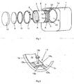
- depicts an arrangement provided with components for fitting a particle filter unit in a silencer,
- Fig. 2
- depicts a fastening device for fastening the particle filter in the silencer and
- Fig. 3
- is a sectional view of the particle filter unit in a fitted state inside the silencer.
-
Fig. 1 depicts asilencer 1 suited to being placed in an exhaust line which leads the exhaust gases out from a combustion engine of a vehicle. The silencer has an inlet aperture and an outlet aperture for exhaust gases, although these apertures are situated on sides of the silencer which are not visible inFig. 1 . The silencer has an internal exhaust passage which extends between the inlet aperture and the outlet aperture. The silencer has in a wall surface anaperture 1a which leads to a cylindrical space in atubular element 1b for accommodating aparticle filter unit 2. This tubular element forms part of the exhaust passage through the silencer. The particle filter unit comprises atubular wall section 3 enclosing aparticle filter 4 which is intended to filter out soot particles from the exhaust gases. The silencer may with advantage contain also an oxidation catalyst and an SCR catalyst. An oxidation catalyst will oxidise nitrogen monoxide NO to nitrogen dioxide NO2, increasing the proportion of nitrogen dioxide in the exhaust gases so that an SCR catalyst situated downstream can achieve optimum reduction of the nitrogen oxides NOx in the exhaust gases. - The
particle filter unit 2 is provided at a forward first end with anannular gasket 5 which extends round the periphery of thetubular wall section 3 and which may be made of graphite. Astop ring 6 is provided close to the gasket to keep the gasket in an intended position when the particle filter is being inserted into the silencer. An annularresilient component 7 is placed round thetubular wall section 3 at an axial distance from thegasket 5. The annular resilient component is with advantage made of spring steel which can undergo relatively large deformations without suffering fractures or permanent changes of shape. - The
particle filter unit 2 is provided at a rear second end with threegripping means 8 fastened at appropriate mutual spacing round the periphery of thetubular wall section 3. These gripping means are intended to be gripped by a tool when the particle filter unit is to be fitted in/removed from the silencer. Each of them is also used here to fasten the particle filter unit in the silencer by means of threefastening devices 13 which are fastenable inside the silencer close to theaperture 1a. Acover 9 fitted in conjunction with anannular gasket 10 which is with advantage made of graphite is used to close theaperture 1a. The cover and the gasket are fastened at the sides of theaperture 1a by means of a V-clamp 11. Finally, aprotective device 12 is fastened on the silencer at a position outside thecover 10. -
Fig. 2 depicts one of thefastening devices 13 in more detail. It comprises a fixedportion 13a firmly anchored in a suitable way in the silencer, e.g. by welding. This fixed portion has a platelike element provided with a long and narrow hole. The fastening device comprises a movable portion 13b consisting of a first platelike element 13b1 and a second platelike element 13b2 which are connected to one another at an end surface. Assembling thefastening device 13 involves pushing the movable portion 13b on from the side of the fixedportion 13a so that the first element 13b1 is above the fixedportion 13a and the second element 13b2 is below the fixedportion 13a. The first element 13b1 and the second element 13b2 each have a hole running through them to accommodate a screw means 13c. When the movable portion 13b has been pushed onto the fixedportion 13a, a screw means 13c can be inserted down through the first element 13b1 of the movable portion, the elongate hole in the fixed portion and the hole in the second element 13b1 of the movable portion. So long as the screw means 13c is not pulled out, the elongate hole in the fixedportion 13a will allow movement of the movable portion 13b in a longitudinal direction relative to theparticle filter unit 2. The first element 13b1 of the movable portion has a stop portion 13b3 adapted to coming into contact with an end surface of the particle filter unit. Fastening the particle filter unit in the silencer in a fitting position involves the movable portion 13b being moved to a position at which the stop portion 13b3 comes into contact with the particle filter unit. The screw means 13c will then be tightened so that the particle filter unit is fixed in an intended fitting position in the silencer. The fixedportion 13a of the fastening device creates aspace 1c between thetubular element 1b and the edges which define theaperture 1a. Thisspace 1c is a portion of the exhaust passage which is adjacent to the portion of the exhaust passage which is defined by the tubular element. -
Fig. 3 is a sectional view of theparticle filter unit 2 in a fitted state inside the silencer. Theparticle filter 4 is made of porous material with thinelongate ducts 4a which are provided withstop surfaces 4b at appropriate points. These stop surfaces force the exhaust gases to go into adjacent elongate ducts in the particle filter. Theporous walls 4c of the ducts allow the exhaust gases, but not soot particles, to pass through. The soot particles thus become trapped inside the particle filter, in which they are subsequently intended to be burnt, but for this to take place a high temperature needs to be maintained in the particle filter, which in many operating situations is not possible. The particle filter inevitably becomes obstructed over time and needs replacing. - The
particle filter unit 2 has here been inserted to an extreme position defined by astop surface 1b1. Thestop ring 6 prevents displacement of thegasket 5 from an intended fastening position on the particle filter unit. The annular resilient component comprises afirst contact portion 7a in contact with a peripheral surface of the particle filter unit, asecond contact portion 7b in contact with an internal wall surface of thetubular element 1b, and athird contact portion 7c in contact with a peripheral surface of the particle filter unit. Thecontact portions 7a-c are at axial distances from one another. Thesecond contact portion 7b is at a radial distance from the tubular element. Thefirst contact portion 7a and the second contact portion are at opposite edges of the annular resilient component and thesecond contact portion 7b is substantially halfway between said edges. The annular resilient component has an external surface which is, from thefirst contact portion 7a towards thesecond contact portion 7b, at a progressively increasing distance from theparticle filter unit 2. The annular resilient component has an external surface which is, from thesecond contact portion 7b towards thethird contact portion 7c, at a progressively decreasing distance from the particle filter unit. The annular resilient component thus has a V-shaped cross-section. It has at the two edges slitlike recesses 7d andintermediate limb portions 7e which embrace thefirst contact surface 7a and thethird contact surface 7c. The annularresilient component 7 thus acquires good resilient characteristics in a radial direction within thetubular element 1b. - The first step in removing a
particle filter unit 2 from thesilencer 1 is to unscrew theprotective plate 12 from the silencer so that thecover 9 becomes visible. The V-clamp 11 is then released so that thecover 9 and thegasket 10 can be removed to expose theaperture 1a in the silencer. This is followed by releasing the screw means 13c and thefastening devices 13 which hold the particle filter unit firmly inside the silencer. It will now be possible to pull the particle filter unit out of the silencer. The presence of the annularresilient component 7 and thegasket 5 situated between the particle filter unit and thetubular element 1b makes it difficult to pull the particle filter unit out of the silencer without auxiliary means. A suitable tool is therefore fastened in thegripping means 8 and is anchored on one or more predetermined fastening points on the silencer. The tool is activated so as to pull the particle filter unit out of thetubular element 1b in the silencer. The particle filter unit may then be sent away for scrapping or cleaning. Thegaskets
A completely new or renovated particle filter unit which is to be fitted in the silencer will be provided with anew gasket 5 at the forward end. The particle filter unit will then be inserted in the silencer via theaperture 1a so that its first end is fitted at a position adjacent to thetubular element 1b. The tool is fitted on thegripping means 8 and one or more predetermined fastening points on the silencer. The tool is then activated to push the particle filter unit into the tubular element. The annularresilient component 7 centres the particle filter unit in the tubular element during this movement, eliminating any risk of the particle filter unit and the gasket assuming an oblique position relative to the tubular element, thus ensuring that the gasket will not be damaged. The pushing movement ends when the particle filter unit reaches thestop surface 1b1. Alternatively, the tool may have a travel length such that the particle filter unit will always be at a desired position when the tool reaches an extreme position. Thefastening devices 13 are then fitted as mentioned above so that the particle filter unit is fixed in a longitudinal direction. Thecover 9 and anew gasket 10 are fixed close to an edge surface of theaperture 1a by means of the V-clamp 11. Finally, theprotective plate 12 is fastened by screws on the silencer so that it masks the cover and the V-clamp. - The annular
resilient component 7 substantially eliminates any risk of damage to thegasket 5 during the fitting work. There is therefore no risk of any of the exhaust gases being led past theparticle filter 4 and not being filtered. The risk of internal leakage is thus substantially eliminated. Thegasket 10 and the V-clamp provide the cover with a tight fit close to theaperture 1a, with consequently no risk of the exhaust gases leaking out via theaperture 1a. The risk of warm exhaust gases leaking out from the silencer is therefore very slight. - The invention is in no way restricted to the embodiments described but may be varied freely within the scopes of the claims.
Claims (4)
- An arrangement for fitting an exhaust cleaning unit (2) in an exhaust passage, the arrangement comprises a fastening device (13) by which it is possible to releasably fasten the exhaust cleaning unit (2) in an intended fitting position in said exhaust passage through an aperture (1a) with a releasable fittable cover (9), wherein the exhaust cleaning unit (2) is fitted in the exhaust passage in a silencer (1) whereby the arrangement comprises a gasket (5) fitted round the exhaust cleaning unit to serve as a seal between the exhaust cleaning unit (2) and an internal wall surface (1b) of the exhaust passage and an annular resilient component (7) which is fitted round the exhaust cleaning unit (2) at a distance from the gasket (5) and which has a first contact portion (7a) adapted to coming into contact with said wall surface (3) of the exhaust cleaning unit (2) and a second contact portion (7b) adapted to coming into contact with the wall surface of the exhaust passage when the exhaust cleaning unit (2) is in a fitted state in the exhaust passage, and that the annular resilient component (7) has the characteristic of keeping the exhaust cleaning unit (2) in a centred position in the exhaust passage with a spring force, characterised in that the second contact portion (7b) is at an axial distance from the first contact portion (7a) and the annular resilient component (7) has an external surface which is, from the first contact portion (7a) towards the second contact portion (7b), at a progressively increasing radial distance from the exhaust cleaning unit (2).
- An arrangement according to claim 1, characterised in that the annular resilient component (7) has slitlike recesses (7d) and intermediate limb portions (7e) which embrace the first contact surface (7a) or the second contact surface (7b).
- An arrangement according to any one of the foregoing claims, characterised in that the exhaust cleaning unit (2) is provided with at least one gripping means (8) for a tool intended to be used to push the exhaust cleaning unit (2) in to a fitting position in the exhaust passage and/or to pull the exhaust cleaning unit (2) out from the fitting position in the exhaust passage.
- An arrangement according to any one of the foregoing claims, characterised in that the exhaust cleaning unit is a particle filter unit (2).
Applications Claiming Priority (2)
| Application Number | Priority Date | Filing Date | Title |
|---|---|---|---|
| SE1151109A SE536327C2 (en) | 2011-11-22 | 2011-11-22 | Arrangement for mounting an exhaust-cleaning unit in an exhaust passage |
| PCT/SE2012/051238 WO2013077797A1 (en) | 2011-11-22 | 2012-11-13 | Arrangement for fitting an exhaust cleaning unit in an exhaust passage |
Publications (3)
| Publication Number | Publication Date |
|---|---|
| EP2783080A1 EP2783080A1 (en) | 2014-10-01 |
| EP2783080A4 EP2783080A4 (en) | 2015-07-15 |
| EP2783080B1 true EP2783080B1 (en) | 2016-09-28 |
Family
ID=48470134
Family Applications (1)
| Application Number | Title | Priority Date | Filing Date |
|---|---|---|---|
| EP12852299.2A Not-in-force EP2783080B1 (en) | 2011-11-22 | 2012-11-13 | Arrangement for fitting an exhaust cleaning unit in an exhaust passage |
Country Status (10)
| Country | Link |
|---|---|
| US (1) | US9518500B2 (en) |
| EP (1) | EP2783080B1 (en) |
| JP (1) | JP2015505926A (en) |
| KR (1) | KR20140088231A (en) |
| CN (1) | CN103946493B (en) |
| BR (1) | BR112014012255A2 (en) |
| IN (1) | IN2014DN03243A (en) |
| RU (1) | RU2563443C1 (en) |
| SE (1) | SE536327C2 (en) |
| WO (1) | WO2013077797A1 (en) |
Families Citing this family (7)
| Publication number | Priority date | Publication date | Assignee | Title |
|---|---|---|---|---|
| SE535473C2 (en) * | 2010-12-03 | 2012-08-21 | Scania Cv Ab | Insert, holder and exhaust after-treatment unit |
| CN103256107B (en) * | 2013-06-04 | 2015-08-12 | 天津亿利汽车环保科技有限公司 | A kind of SCR reprocessing catalyst |
| DE102015209681B4 (en) | 2015-05-27 | 2023-05-17 | Purem GmbH | Exhaust gas treatment device with exchangeable insert |
| WO2017116329A1 (en) * | 2015-12-31 | 2017-07-06 | Ford Otomotiv Sanayi A.Ş. | Structurally improved exhaust treatment assembly and associated treatment components thereof |
| US10036296B1 (en) * | 2017-03-29 | 2018-07-31 | Caterpillar Inc. | Catalyst substrate mounting mat |
| CN109395584B (en) * | 2018-12-30 | 2024-03-19 | 盐城高玛电子设备有限公司 | Photo-oxygen catalytic purification equipment for waste gas of baking varnish house |
| SE543012C2 (en) * | 2019-04-23 | 2020-09-29 | Scania Cv Ab | An emissions control device comprising a threaded disassembling element |
Family Cites Families (14)
| Publication number | Priority date | Publication date | Assignee | Title |
|---|---|---|---|---|
| US3675398A (en) * | 1970-10-15 | 1972-07-11 | Lawrence P Giarrizzo | Exhaust filter attachment |
| DE3632059C1 (en) * | 1986-09-20 | 1988-03-31 | Bayerische Motoren Werke Ag | Holding device for the monoliths of an exhaust gas catalyst |
| DE3700070A1 (en) | 1987-01-02 | 1988-07-14 | Eberspaecher J | DEVICE FOR CATALYTIC CLEANING OF VEHICLE ENGINE EXHAUST GAS |
| DE10137878A1 (en) | 2001-08-02 | 2003-02-27 | Emitec Emissionstechnologie | Exhaust gas catalytic converter with expansion-compensating bearing |
| JP3782341B2 (en) * | 2001-12-06 | 2006-06-07 | 本田技研工業株式会社 | Humidity sensor failure detection method |
| US7100736B2 (en) * | 2003-10-14 | 2006-09-05 | Fleetguard, Inc. | Serviceable muffler |
| JP4395360B2 (en) * | 2003-11-27 | 2010-01-06 | 日野自動車株式会社 | Exhaust purification device |
| DE10357953B4 (en) | 2003-12-11 | 2006-10-26 | Emitec Gesellschaft Für Emissionstechnologie Mbh | Holder for an exhaust gas purification component of an exhaust system |
| JP4340137B2 (en) | 2003-12-12 | 2009-10-07 | 日野自動車株式会社 | Exhaust purification equipment |
| JP5361374B2 (en) | 2006-07-03 | 2013-12-04 | 日本碍子株式会社 | Honeycomb structure and manufacturing method thereof |
| EP2110528B2 (en) * | 2008-04-18 | 2017-04-19 | Daimler AG | Apparatus for treating an exhaust gas stream with removable module |
| US8281575B2 (en) * | 2008-07-31 | 2012-10-09 | Caterpillar Inc. | Emissions control filter assembly and system |
| DE102009012892B4 (en) | 2009-03-12 | 2022-06-15 | Friedrich Boysen Gmbh & Co. Kg | Diesel Particulate Filter Assembly |
| US8136770B2 (en) * | 2009-08-24 | 2012-03-20 | International Engine Intellectual Property Company, Llc | Mount for exhaust system components |
-
2011
- 2011-11-22 SE SE1151109A patent/SE536327C2/en not_active IP Right Cessation
-
2012
- 2012-11-13 CN CN201280057147.3A patent/CN103946493B/en not_active Expired - Fee Related
- 2012-11-13 EP EP12852299.2A patent/EP2783080B1/en not_active Not-in-force
- 2012-11-13 BR BR112014012255A patent/BR112014012255A2/en not_active IP Right Cessation
- 2012-11-13 RU RU2014125258/06A patent/RU2563443C1/en not_active IP Right Cessation
- 2012-11-13 KR KR1020147017106A patent/KR20140088231A/en not_active Ceased
- 2012-11-13 WO PCT/SE2012/051238 patent/WO2013077797A1/en not_active Ceased
- 2012-11-13 JP JP2014543446A patent/JP2015505926A/en active Pending
- 2012-11-13 US US14/359,639 patent/US9518500B2/en not_active Expired - Fee Related
- 2012-11-13 IN IN3243DEN2014 patent/IN2014DN03243A/en unknown
Also Published As
| Publication number | Publication date |
|---|---|
| IN2014DN03243A (en) | 2015-05-22 |
| WO2013077797A1 (en) | 2013-05-30 |
| SE1151109A1 (en) | 2013-05-23 |
| RU2563443C1 (en) | 2015-09-20 |
| BR112014012255A2 (en) | 2017-05-30 |
| CN103946493A (en) | 2014-07-23 |
| EP2783080A4 (en) | 2015-07-15 |
| JP2015505926A (en) | 2015-02-26 |
| US9518500B2 (en) | 2016-12-13 |
| SE536327C2 (en) | 2013-08-20 |
| KR20140088231A (en) | 2014-07-09 |
| US20140298782A1 (en) | 2014-10-09 |
| EP2783080A1 (en) | 2014-10-01 |
| CN103946493B (en) | 2018-02-16 |
Similar Documents
| Publication | Publication Date | Title |
|---|---|---|
| US9518500B2 (en) | Arrangement for fitting an exhaust cleaning unit in an exhaust passage | |
| US7550024B2 (en) | Serviceable exhaust aftertreatment assembly and method | |
| US6632406B1 (en) | Device for removing pollution from exhaust gases | |
| US20040109795A1 (en) | Cleanable device for depolluting an engine exhaust gases | |
| JP6789405B2 (en) | Pipe clamps and pipe fittings with sensor housing | |
| US7100736B2 (en) | Serviceable muffler | |
| CN104018912B (en) | System and method for accommodating post-processing block | |
| KR102161412B1 (en) | Exhaust gas cleaning apparatus | |
| CA2443427A1 (en) | Muffler assembly | |
| CN110520606B (en) | Clamping device and using method thereof | |
| KR100791644B1 (en) | Clamp fastening structure of vehicle smoke reduction device | |
| WO2014081377A1 (en) | Arrangement and method for fitting of exhaust cleaning units | |
| US20160363020A1 (en) | Unidirectional Flow Diesel Particulate Filter | |
| EP2646666B1 (en) | Insert, holder and post-treatment unit for exhaust gases | |
| EP3981991B1 (en) | A vehicle body comprising a piping with a fixing structure | |
| EP3959425B1 (en) | An emissions control device comprising a threaded disassembling element | |
| US20080136172A1 (en) | Tapered annular gasket and joint for use of same | |
| EP3594465B1 (en) | Mounting structure of exhaust gas cleaning apparatus | |
| JP2018127934A (en) | Seal device and exhaust system | |
| WO2025137425A1 (en) | Aftertreatment system including aftertreatment component cartridge with adaptor |
Legal Events
| Date | Code | Title | Description |
|---|---|---|---|
| PUAI | Public reference made under article 153(3) epc to a published international application that has entered the european phase |
Free format text: ORIGINAL CODE: 0009012 |
|
| 17P | Request for examination filed |
Effective date: 20140623 |
|
| AK | Designated contracting states |
Kind code of ref document: A1 Designated state(s): AL AT BE BG CH CY CZ DE DK EE ES FI FR GB GR HR HU IE IS IT LI LT LU LV MC MK MT NL NO PL PT RO RS SE SI SK SM TR |
|
| DAX | Request for extension of the european patent (deleted) | ||
| RA4 | Supplementary search report drawn up and despatched (corrected) |
Effective date: 20150615 |
|
| RIC1 | Information provided on ipc code assigned before grant |
Ipc: F01N 13/18 20100101ALI20150609BHEP Ipc: F01N 3/021 20060101AFI20150609BHEP Ipc: F01N 3/28 20060101ALI20150609BHEP |
|
| GRAP | Despatch of communication of intention to grant a patent |
Free format text: ORIGINAL CODE: EPIDOSNIGR1 |
|
| INTG | Intention to grant announced |
Effective date: 20160520 |
|
| GRAS | Grant fee paid |
Free format text: ORIGINAL CODE: EPIDOSNIGR3 |
|
| GRAA | (expected) grant |
Free format text: ORIGINAL CODE: 0009210 |
|
| AK | Designated contracting states |
Kind code of ref document: B1 Designated state(s): AL AT BE BG CH CY CZ DE DK EE ES FI FR GB GR HR HU IE IS IT LI LT LU LV MC MK MT NL NO PL PT RO RS SE SI SK SM TR |
|
| REG | Reference to a national code |
Ref country code: GB Ref legal event code: FG4D |
|
| REG | Reference to a national code |
Ref country code: CH Ref legal event code: EP |
|
| REG | Reference to a national code |
Ref country code: AT Ref legal event code: REF Ref document number: 832961 Country of ref document: AT Kind code of ref document: T Effective date: 20161015 |
|
| REG | Reference to a national code |
Ref country code: IE Ref legal event code: FG4D |
|
| REG | Reference to a national code |
Ref country code: DE Ref legal event code: R096 Ref document number: 602012023625 Country of ref document: DE |
|
| REG | Reference to a national code |
Ref country code: FR Ref legal event code: PLFP Year of fee payment: 5 |
|
| REG | Reference to a national code |
Ref country code: LT Ref legal event code: MG4D |
|
| PG25 | Lapsed in a contracting state [announced via postgrant information from national office to epo] |
Ref country code: FI Free format text: LAPSE BECAUSE OF FAILURE TO SUBMIT A TRANSLATION OF THE DESCRIPTION OR TO PAY THE FEE WITHIN THE PRESCRIBED TIME-LIMIT Effective date: 20160928 Ref country code: NO Free format text: LAPSE BECAUSE OF FAILURE TO SUBMIT A TRANSLATION OF THE DESCRIPTION OR TO PAY THE FEE WITHIN THE PRESCRIBED TIME-LIMIT Effective date: 20161228 Ref country code: RS Free format text: LAPSE BECAUSE OF FAILURE TO SUBMIT A TRANSLATION OF THE DESCRIPTION OR TO PAY THE FEE WITHIN THE PRESCRIBED TIME-LIMIT Effective date: 20160928 Ref country code: HR Free format text: LAPSE BECAUSE OF FAILURE TO SUBMIT A TRANSLATION OF THE DESCRIPTION OR TO PAY THE FEE WITHIN THE PRESCRIBED TIME-LIMIT Effective date: 20160928 Ref country code: LT Free format text: LAPSE BECAUSE OF FAILURE TO SUBMIT A TRANSLATION OF THE DESCRIPTION OR TO PAY THE FEE WITHIN THE PRESCRIBED TIME-LIMIT Effective date: 20160928 |
|
| REG | Reference to a national code |
Ref country code: NL Ref legal event code: MP Effective date: 20160928 |
|
| REG | Reference to a national code |
Ref country code: AT Ref legal event code: MK05 Ref document number: 832961 Country of ref document: AT Kind code of ref document: T Effective date: 20160928 |
|
| PG25 | Lapsed in a contracting state [announced via postgrant information from national office to epo] |
Ref country code: GR Free format text: LAPSE BECAUSE OF FAILURE TO SUBMIT A TRANSLATION OF THE DESCRIPTION OR TO PAY THE FEE WITHIN THE PRESCRIBED TIME-LIMIT Effective date: 20161229 Ref country code: SE Free format text: LAPSE BECAUSE OF FAILURE TO SUBMIT A TRANSLATION OF THE DESCRIPTION OR TO PAY THE FEE WITHIN THE PRESCRIBED TIME-LIMIT Effective date: 20160928 Ref country code: BE Free format text: LAPSE BECAUSE OF NON-PAYMENT OF DUE FEES Effective date: 20161130 Ref country code: NL Free format text: LAPSE BECAUSE OF FAILURE TO SUBMIT A TRANSLATION OF THE DESCRIPTION OR TO PAY THE FEE WITHIN THE PRESCRIBED TIME-LIMIT Effective date: 20160928 Ref country code: LV Free format text: LAPSE BECAUSE OF FAILURE TO SUBMIT A TRANSLATION OF THE DESCRIPTION OR TO PAY THE FEE WITHIN THE PRESCRIBED TIME-LIMIT Effective date: 20160928 |
|
| PG25 | Lapsed in a contracting state [announced via postgrant information from national office to epo] |
Ref country code: RO Free format text: LAPSE BECAUSE OF FAILURE TO SUBMIT A TRANSLATION OF THE DESCRIPTION OR TO PAY THE FEE WITHIN THE PRESCRIBED TIME-LIMIT Effective date: 20160928 Ref country code: EE Free format text: LAPSE BECAUSE OF FAILURE TO SUBMIT A TRANSLATION OF THE DESCRIPTION OR TO PAY THE FEE WITHIN THE PRESCRIBED TIME-LIMIT Effective date: 20160928 |
|
| PG25 | Lapsed in a contracting state [announced via postgrant information from national office to epo] |
Ref country code: PL Free format text: LAPSE BECAUSE OF FAILURE TO SUBMIT A TRANSLATION OF THE DESCRIPTION OR TO PAY THE FEE WITHIN THE PRESCRIBED TIME-LIMIT Effective date: 20160928 Ref country code: AT Free format text: LAPSE BECAUSE OF FAILURE TO SUBMIT A TRANSLATION OF THE DESCRIPTION OR TO PAY THE FEE WITHIN THE PRESCRIBED TIME-LIMIT Effective date: 20160928 Ref country code: CZ Free format text: LAPSE BECAUSE OF FAILURE TO SUBMIT A TRANSLATION OF THE DESCRIPTION OR TO PAY THE FEE WITHIN THE PRESCRIBED TIME-LIMIT Effective date: 20160928 Ref country code: SK Free format text: LAPSE BECAUSE OF FAILURE TO SUBMIT A TRANSLATION OF THE DESCRIPTION OR TO PAY THE FEE WITHIN THE PRESCRIBED TIME-LIMIT Effective date: 20160928 Ref country code: IS Free format text: LAPSE BECAUSE OF FAILURE TO SUBMIT A TRANSLATION OF THE DESCRIPTION OR TO PAY THE FEE WITHIN THE PRESCRIBED TIME-LIMIT Effective date: 20170128 Ref country code: BG Free format text: LAPSE BECAUSE OF FAILURE TO SUBMIT A TRANSLATION OF THE DESCRIPTION OR TO PAY THE FEE WITHIN THE PRESCRIBED TIME-LIMIT Effective date: 20161228 Ref country code: ES Free format text: LAPSE BECAUSE OF FAILURE TO SUBMIT A TRANSLATION OF THE DESCRIPTION OR TO PAY THE FEE WITHIN THE PRESCRIBED TIME-LIMIT Effective date: 20160928 Ref country code: PT Free format text: LAPSE BECAUSE OF FAILURE TO SUBMIT A TRANSLATION OF THE DESCRIPTION OR TO PAY THE FEE WITHIN THE PRESCRIBED TIME-LIMIT Effective date: 20170130 Ref country code: BE Free format text: LAPSE BECAUSE OF FAILURE TO SUBMIT A TRANSLATION OF THE DESCRIPTION OR TO PAY THE FEE WITHIN THE PRESCRIBED TIME-LIMIT Effective date: 20160928 Ref country code: SM Free format text: LAPSE BECAUSE OF FAILURE TO SUBMIT A TRANSLATION OF THE DESCRIPTION OR TO PAY THE FEE WITHIN THE PRESCRIBED TIME-LIMIT Effective date: 20160928 |
|
| REG | Reference to a national code |
Ref country code: DE Ref legal event code: R097 Ref document number: 602012023625 Country of ref document: DE |
|
| PG25 | Lapsed in a contracting state [announced via postgrant information from national office to epo] |
Ref country code: IT Free format text: LAPSE BECAUSE OF FAILURE TO SUBMIT A TRANSLATION OF THE DESCRIPTION OR TO PAY THE FEE WITHIN THE PRESCRIBED TIME-LIMIT Effective date: 20160928 |
|
| REG | Reference to a national code |
Ref country code: CH Ref legal event code: PL |
|
| PG25 | Lapsed in a contracting state [announced via postgrant information from national office to epo] |
Ref country code: CH Free format text: LAPSE BECAUSE OF NON-PAYMENT OF DUE FEES Effective date: 20161130 Ref country code: DK Free format text: LAPSE BECAUSE OF FAILURE TO SUBMIT A TRANSLATION OF THE DESCRIPTION OR TO PAY THE FEE WITHIN THE PRESCRIBED TIME-LIMIT Effective date: 20160928 Ref country code: LI Free format text: LAPSE BECAUSE OF NON-PAYMENT OF DUE FEES Effective date: 20161130 |
|
| PLBE | No opposition filed within time limit |
Free format text: ORIGINAL CODE: 0009261 |
|
| STAA | Information on the status of an ep patent application or granted ep patent |
Free format text: STATUS: NO OPPOSITION FILED WITHIN TIME LIMIT |
|
| REG | Reference to a national code |
Ref country code: IE Ref legal event code: MM4A |
|
| 26N | No opposition filed |
Effective date: 20170629 |
|
| PG25 | Lapsed in a contracting state [announced via postgrant information from national office to epo] |
Ref country code: LU Free format text: LAPSE BECAUSE OF NON-PAYMENT OF DUE FEES Effective date: 20161130 |
|
| REG | Reference to a national code |
Ref country code: FR Ref legal event code: PLFP Year of fee payment: 6 |
|
| PG25 | Lapsed in a contracting state [announced via postgrant information from national office to epo] |
Ref country code: IE Free format text: LAPSE BECAUSE OF NON-PAYMENT OF DUE FEES Effective date: 20161113 Ref country code: SI Free format text: LAPSE BECAUSE OF FAILURE TO SUBMIT A TRANSLATION OF THE DESCRIPTION OR TO PAY THE FEE WITHIN THE PRESCRIBED TIME-LIMIT Effective date: 20160928 |
|
| PGFP | Annual fee paid to national office [announced via postgrant information from national office to epo] |
Ref country code: FR Payment date: 20171012 Year of fee payment: 6 |
|
| PGFP | Annual fee paid to national office [announced via postgrant information from national office to epo] |
Ref country code: GB Payment date: 20171108 Year of fee payment: 6 |
|
| PG25 | Lapsed in a contracting state [announced via postgrant information from national office to epo] |
Ref country code: HU Free format text: LAPSE BECAUSE OF FAILURE TO SUBMIT A TRANSLATION OF THE DESCRIPTION OR TO PAY THE FEE WITHIN THE PRESCRIBED TIME-LIMIT; INVALID AB INITIO Effective date: 20121113 |
|
| PG25 | Lapsed in a contracting state [announced via postgrant information from national office to epo] |
Ref country code: MC Free format text: LAPSE BECAUSE OF FAILURE TO SUBMIT A TRANSLATION OF THE DESCRIPTION OR TO PAY THE FEE WITHIN THE PRESCRIBED TIME-LIMIT Effective date: 20160928 Ref country code: MK Free format text: LAPSE BECAUSE OF FAILURE TO SUBMIT A TRANSLATION OF THE DESCRIPTION OR TO PAY THE FEE WITHIN THE PRESCRIBED TIME-LIMIT Effective date: 20160928 Ref country code: CY Free format text: LAPSE BECAUSE OF FAILURE TO SUBMIT A TRANSLATION OF THE DESCRIPTION OR TO PAY THE FEE WITHIN THE PRESCRIBED TIME-LIMIT Effective date: 20160928 |
|
| PG25 | Lapsed in a contracting state [announced via postgrant information from national office to epo] |
Ref country code: MT Free format text: LAPSE BECAUSE OF NON-PAYMENT OF DUE FEES Effective date: 20161113 |
|
| PG25 | Lapsed in a contracting state [announced via postgrant information from national office to epo] |
Ref country code: AL Free format text: LAPSE BECAUSE OF FAILURE TO SUBMIT A TRANSLATION OF THE DESCRIPTION OR TO PAY THE FEE WITHIN THE PRESCRIBED TIME-LIMIT Effective date: 20160928 Ref country code: TR Free format text: LAPSE BECAUSE OF FAILURE TO SUBMIT A TRANSLATION OF THE DESCRIPTION OR TO PAY THE FEE WITHIN THE PRESCRIBED TIME-LIMIT Effective date: 20160928 |
|
| GBPC | Gb: european patent ceased through non-payment of renewal fee |
Effective date: 20181113 |
|
| PG25 | Lapsed in a contracting state [announced via postgrant information from national office to epo] |
Ref country code: FR Free format text: LAPSE BECAUSE OF NON-PAYMENT OF DUE FEES Effective date: 20181130 |
|
| PG25 | Lapsed in a contracting state [announced via postgrant information from national office to epo] |
Ref country code: GB Free format text: LAPSE BECAUSE OF NON-PAYMENT OF DUE FEES Effective date: 20181113 |
|
| PGFP | Annual fee paid to national office [announced via postgrant information from national office to epo] |
Ref country code: DE Payment date: 20191029 Year of fee payment: 8 |
|
| REG | Reference to a national code |
Ref country code: DE Ref legal event code: R119 Ref document number: 602012023625 Country of ref document: DE |
|
| PG25 | Lapsed in a contracting state [announced via postgrant information from national office to epo] |
Ref country code: DE Free format text: LAPSE BECAUSE OF NON-PAYMENT OF DUE FEES Effective date: 20210601 |