EP2782828B1 - Test apparatus for avionic sensors and method of testing avionic sensors - Google Patents
Test apparatus for avionic sensors and method of testing avionic sensors Download PDFInfo
- Publication number
- EP2782828B1 EP2782828B1 EP12808504.0A EP12808504A EP2782828B1 EP 2782828 B1 EP2782828 B1 EP 2782828B1 EP 12808504 A EP12808504 A EP 12808504A EP 2782828 B1 EP2782828 B1 EP 2782828B1
- Authority
- EP
- European Patent Office
- Prior art keywords
- avionic
- helicopter
- test
- casing
- pod
- Prior art date
- Legal status (The legal status is an assumption and is not a legal conclusion. Google has not performed a legal analysis and makes no representation as to the accuracy of the status listed.)
- Active
Links
Images
Classifications
-
- B—PERFORMING OPERATIONS; TRANSPORTING
- B64—AIRCRAFT; AVIATION; COSMONAUTICS
- B64D—EQUIPMENT FOR FITTING IN OR TO AIRCRAFT; FLIGHT SUITS; PARACHUTES; ARRANGEMENT OR MOUNTING OF POWER PLANTS OR PROPULSION TRANSMISSIONS IN AIRCRAFT
- B64D9/00—Equipment for handling freight; Equipment for facilitating passenger embarkation or the like
-
- B—PERFORMING OPERATIONS; TRANSPORTING
- B64—AIRCRAFT; AVIATION; COSMONAUTICS
- B64D—EQUIPMENT FOR FITTING IN OR TO AIRCRAFT; FLIGHT SUITS; PARACHUTES; ARRANGEMENT OR MOUNTING OF POWER PLANTS OR PROPULSION TRANSMISSIONS IN AIRCRAFT
- B64D1/00—Dropping, ejecting, releasing or receiving articles, liquids, or the like, in flight
- B64D1/22—Taking-up articles from earth's surface
-
- B—PERFORMING OPERATIONS; TRANSPORTING
- B64—AIRCRAFT; AVIATION; COSMONAUTICS
- B64F—GROUND OR AIRCRAFT-CARRIER-DECK INSTALLATIONS SPECIALLY ADAPTED FOR USE IN CONNECTION WITH AIRCRAFT; DESIGNING, MANUFACTURING, ASSEMBLING, CLEANING, MAINTAINING OR REPAIRING AIRCRAFT, NOT OTHERWISE PROVIDED FOR; HANDLING, TRANSPORTING, TESTING OR INSPECTING AIRCRAFT COMPONENTS, NOT OTHERWISE PROVIDED FOR
- B64F5/00—Designing, manufacturing, assembling, cleaning, maintaining or repairing aircraft, not otherwise provided for; Handling, transporting, testing or inspecting aircraft components, not otherwise provided for
- B64F5/60—Testing or inspecting aircraft components or systems
Definitions
- the present invention relates to a test apparatus for avionic sensors and to a method for testing avionic sensors.
- test pods for avionic sensors are fixed to the wing of an aircraft, for example, in place of a tank or a weapon, in the case of military aircraft.
- test pod is effective, but generally involves substantial costs, which are sometimes difficult to bear. In fact, the purchase or long-term renting of a suitable aeroplane for this purpose is extremely expensive.
- a test pod hooked to the wing of a subsonic plane or even more so to the wing of a supersonic plane must meet stringent aerodynamic and weight requirements, in order to avoid critical situations during flight. In addition to the intrinsic cost associated with designing pods with such requirements, often it is not possible to test more than one sensor at a time. Test campaigns are therefore long, require a large number of flights and, in consequence, are expensive.
- the sensors to be tested could be installed directly on aeroplanes specifically modified to perform the tests.
- the maintenance and modification costs of an aeroplane are extremely high in this case as well.
- WO 02/075235 A discloses a stealth airborne suspended operating system, that includes a suspension to an aircraft, e.g. a helicopter and a platform, suspended from the suspension device.
- An operating system such as an imaging sensor, is carried by the platform.
- the object of the present invention is to provide a test apparatus for avionic sensors and a method of testing avionic sensors that enable the described limitations to be overcome and, in particular, allow avionic sensors to be tested at lower costs than those incurred with known test pods.
- test apparatus for avionic sensors and method of testing avionic sensors are provided as defined in claims 1 and 11 respectively.
- a test apparatus for avionic sensors comprises a helicopter 2 and an avionic sensor test pod 3 connected to the helicopter 2 by a cable suspension system 4.
- the cable suspension system 4 comprises a main cable 5 and a plurality of ropes 6, each one connected between the main cable 5 and a respective mounting point on the pod 3.
- the main cable 5 is a metal cable, possibly fastened to a winch (not shown for simplicity) on board the helicopter 2.
- the pod 3 comprises a casing 7, inside which one or more avionic sensors to be tested are housed ( Figure 3 ).
- the casing 7 ( Figures 1-3 ) has the form of an elongated box-like body, streamlined at the end that defines the nose 7a.
- the casing 7 may be made, for example, of aluminium, steel, fibreglass, carbon fibre or other similar materials.
- the casing 7 is equipped with a tail assembly 8, which has the purpose of avoiding rotation of the pod 3 during flight, in particular around the yaw axis.
- the tail assembly 8 comprises a main fin 10 ( Figures 1 and 3 ), an additional fin 11 ( Figures 1 and 2 ) and stabilizers 12 ( Figure 2 ).
- the main fin 10 and the stabilizers 12 are fastened directly to the casing 7.
- the additional fin 11 is instead placed at one end of a support bar 13 that projects rearwards from the tail of the casing 7. Furthermore, the additional fin 11 is supported such that it is aligned with the main fin 10.
- the casing 7 of the pod 3 is equipped with a plurality of mounting points (indicated by reference numeral 15 in Figure 1 ) for the cable suspension system 4.
- the mounting points 15 are rings fastened to an upper face 7b of the casing 7 and each one receives one end of a respective rope 6 of the cable suspension system 4.
- the connection of the ropes 6 to the mounting points 15 is achieved, for example, by spring catches or quick link connectors, not shown here.
- the mounting points 15 are distributed so that the pod 3 is balanced in flight.
- the casing 7 is also equipped with a radome 17, which in the embodiment described herein extends towards the outside from a lower face 7c.
- the radome 17 is defined by a dome made of a rigid material and is substantially transparent to electromagnetic radiation in an operating frequency band of a radar sensor to be tested, for example, between approximately 200 MHz and 1500 MHz.
- the radome 17 is made, for example, of multi-layered Kevlar, glass and a honeycomb structure, and is shaped to internally house a radar antenna, as described hereinafter.
- the avionic sensors contained inside the casing 7 comprise, in one embodiment, a radar system 18 and a tactical or strategic type of electro-optical system 20.
- the radar system 18 comprises a radar antenna 21, housed inside the radome 17, and a radar processing module 22, which is located inside the casing 7 and is connected to the radar antenna 21.
- the electro-optical system 20 is placed in a forward portion of the casing 7, close to an optical window, and enables optical readings to be taken at great distances (of the order of several tens of kilometres).
- the described sensors have been mentioned by way of non-limitative example.
- the pod 3 could actually comprise different sensors in addition to or in substitution of those mentioned, such as, for example, hyperspectral, IRST, FLIR, satellite data-link and LOS sensors, SIGINT and electronic warfare systems and beacon transponders.
- auxiliary devices are also housed inside the casing 7, as shown schematically in Figure 2 and partially in Figure 1 .
- the auxiliary devices comprise an electric power source 25, a power supply unit 26, a navigation system 27, a high-speed data logger and a communications interface 28.
- the pod 3 is equipped with an electrical connector 30 for connecting an external electric power source 31, placed on board the helicopter 2.
- a power cable 32 runs between the electric power source 31 and the connector 30, along the main cable 5.
- the power supply unit 26 for example an inverter, converts the electricity supply, provided by the internal electric power source 25 or the electric power source 30 on board the helicopter 2e, and distributes it to the users (sensors and auxiliary devices).
- the communications interface 28 also placed inside the casing 7, couples the avionic sensors of the pod 3 in communication with a processing unit 35 located on board the helicopter 2 and is configured to control the sensors, process the received data and display the results of the readings taken and, in particular, is configured to perform test procedures.
- the communications interface 28 connects the processing unit 35 to the radar processing module 22 and the electro-optical system 20, to enable an operator to carry out test procedures during the flight of the helicopter 2 and the pod 3 that is connected to it.
- the communications interface 28 is connected to the processing unit 35 by a network cable 38, which runs along the main cable 5.
- the connection between the communications interface 28 and the processing unit 35 is wireless.
- the described pod advantageously permits a substantial reduction in the costs of the test campaigns of avionic sensors, as well as simplifying the execution thereof.
- the predisposition for hooking up by means of a cable suspension system permits using a helicopter instead of an aeroplane to transport the pod during the tests.
- the design of the pod is much simpler and thus less expensive.
- the aerodynamic requirements of the pod are, in fact, basic ones and may be easily met without the need for complex calculations. It should also be considered that, not infrequently, the aeroplanes used for transporting conventional pods must also be modified to a certain extent. However, modifications of this type are extremely onerous and contribute to making the cost of test campaigns high. The propensity of the pod for cable suspension from a helicopter eliminates the need for any expensive modifications.
Landscapes
- Engineering & Computer Science (AREA)
- Aviation & Aerospace Engineering (AREA)
- Manufacturing & Machinery (AREA)
- Transportation (AREA)
- Testing Or Calibration Of Command Recording Devices (AREA)
- Aiming, Guidance, Guns With A Light Source, Armor, Camouflage, And Targets (AREA)
- Transmission And Conversion Of Sensor Element Output (AREA)
- Investigating Or Analyzing Materials By The Use Of Electric Means (AREA)
- Details Of Aerials (AREA)
Description
- The present invention relates to a test apparatus for avionic sensors and to a method for testing avionic sensors.
- As is known, many onboard aircraft instruments require test campaigns before being installed for use. In particular, radar sensors and other avionic sensors may be tested in flight by using specially provided pods that are mounted on aircraft, possibly modified for the purpose. In this way, it is expected to have the opportunity to test the functionality of the equipment in conditions similar to the effective conditions of use for which the equipment has been designed.
- As a rule, test pods for avionic sensors are fixed to the wing of an aircraft, for example, in place of a tank or a weapon, in the case of military aircraft.
- This type of test pod is effective, but generally involves substantial costs, which are sometimes difficult to bear. In fact, the purchase or long-term renting of a suitable aeroplane for this purpose is extremely expensive. In addition, a test pod hooked to the wing of a subsonic plane or even more so to the wing of a supersonic plane must meet stringent aerodynamic and weight requirements, in order to avoid critical situations during flight. In addition to the intrinsic cost associated with designing pods with such requirements, often it is not possible to test more than one sensor at a time. Test campaigns are therefore long, require a large number of flights and, in consequence, are expensive.
- Alternatively, the sensors to be tested could be installed directly on aeroplanes specifically modified to perform the tests. However, the maintenance and modification costs of an aeroplane are extremely high in this case as well.
-
WO 02/075235 A - The object of the present invention is to provide a test apparatus for avionic sensors and a method of testing avionic sensors that enable the described limitations to be overcome and, in particular, allow avionic sensors to be tested at lower costs than those incurred with known test pods.
- According to the present invention, a test apparatus for avionic sensors and method of testing avionic sensors are provided as defined in
claims 1 and 11 respectively. - For a better understanding of the invention, an embodiment will now be described, purely by way of a non-limitative example and with reference to the attached drawings, where:
-
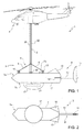
Figure 1 is a side view of a test apparatus for avionic sensors according to an embodiment of the present invention and including an avionic sensor test pod; -
Figure 2 is a plan view of the avionic sensor test pod inFigure 1 ; -
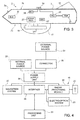
Figure 3 is a schematic, sectional side view, along a longitudinal plane, of the avionic sensor test pod inFigure 1 ; and -
Figure 4 is a simplified block diagram of part of the test apparatus for avionic sensors inFigure 1 . - With reference to
Figures 1 to 3 , a test apparatus for avionic sensors, indicated as a whole by reference numeral 1, comprises ahelicopter 2 and an avionic sensor test pod 3 connected to thehelicopter 2 by a cable suspension system 4. In particular, the cable suspension system 4 comprises amain cable 5 and a plurality of ropes 6, each one connected between themain cable 5 and a respective mounting point on thepod 3. - In one embodiment, the
main cable 5 is a metal cable, possibly fastened to a winch (not shown for simplicity) on board thehelicopter 2. - The
pod 3 comprises acasing 7, inside which one or more avionic sensors to be tested are housed (Figure 3 ). - The casing 7 (
Figures 1-3 ) has the form of an elongated box-like body, streamlined at the end that defines thenose 7a. Thecasing 7 may be made, for example, of aluminium, steel, fibreglass, carbon fibre or other similar materials. - At the opposite end from the
nose 7a, thecasing 7 is equipped with atail assembly 8, which has the purpose of avoiding rotation of thepod 3 during flight, in particular around the yaw axis. - In one embodiment, the
tail assembly 8 comprises a main fin 10 (Figures 1 and3 ), an additional fin 11 (Figures 1 and 2 ) and stabilizers 12 (Figure 2 ). Themain fin 10 and thestabilizers 12 are fastened directly to thecasing 7. Theadditional fin 11 is instead placed at one end of asupport bar 13 that projects rearwards from the tail of thecasing 7. Furthermore, theadditional fin 11 is supported such that it is aligned with themain fin 10. - As previously mentioned, the
casing 7 of thepod 3 is equipped with a plurality of mounting points (indicated byreference numeral 15 inFigure 1 ) for the cable suspension system 4. - In the embodiment described herein, the
mounting points 15 are rings fastened to anupper face 7b of thecasing 7 and each one receives one end of a respective rope 6 of the cable suspension system 4. The connection of the ropes 6 to themounting points 15 is achieved, for example, by spring catches or quick link connectors, not shown here. Themounting points 15 are distributed so that thepod 3 is balanced in flight. Thecasing 7 is also equipped with aradome 17, which in the embodiment described herein extends towards the outside from alower face 7c. Theradome 17 is defined by a dome made of a rigid material and is substantially transparent to electromagnetic radiation in an operating frequency band of a radar sensor to be tested, for example, between approximately 200 MHz and 1500 MHz. Theradome 17 is made, for example, of multi-layered Kevlar, glass and a honeycomb structure, and is shaped to internally house a radar antenna, as described hereinafter. - The avionic sensors contained inside the
casing 7 comprise, in one embodiment, aradar system 18 and a tactical or strategic type of electro-optical system 20. - The
radar system 18 comprises aradar antenna 21, housed inside theradome 17, and aradar processing module 22, which is located inside thecasing 7 and is connected to theradar antenna 21. - The electro-
optical system 20 is placed in a forward portion of thecasing 7, close to an optical window, and enables optical readings to be taken at great distances (of the order of several tens of kilometres). - The described sensors have been mentioned by way of non-limitative example. The
pod 3 could actually comprise different sensors in addition to or in substitution of those mentioned, such as, for example, hyperspectral, IRST, FLIR, satellite data-link and LOS sensors, SIGINT and electronic warfare systems and beacon transponders. - In addition to the sensors, auxiliary devices are also housed inside the
casing 7, as shown schematically inFigure 2 and partially inFigure 1 . - The auxiliary devices comprise an
electric power source 25, apower supply unit 26, anavigation system 27, a high-speed data logger and acommunications interface 28. In addition to these, in one embodiment, thepod 3 is equipped with anelectrical connector 30 for connecting an externalelectric power source 31, placed on board thehelicopter 2. In this second case, apower cable 32 runs between theelectric power source 31 and theconnector 30, along themain cable 5. - The
power supply unit 26, for example an inverter, converts the electricity supply, provided by the internalelectric power source 25 or theelectric power source 30 on board the helicopter 2e, and distributes it to the users (sensors and auxiliary devices). - The
communications interface 28 , also placed inside thecasing 7, couples the avionic sensors of thepod 3 in communication with aprocessing unit 35 located on board thehelicopter 2 and is configured to control the sensors, process the received data and display the results of the readings taken and, in particular, is configured to perform test procedures. In particular, thecommunications interface 28 connects theprocessing unit 35 to theradar processing module 22 and the electro-optical system 20, to enable an operator to carry out test procedures during the flight of thehelicopter 2 and thepod 3 that is connected to it. In one embodiment, thecommunications interface 28 is connected to theprocessing unit 35 by anetwork cable 38, which runs along themain cable 5. In an alternative embodiment, the connection between thecommunications interface 28 and theprocessing unit 35 is wireless. - The described pod advantageously permits a substantial reduction in the costs of the test campaigns of avionic sensors, as well as simplifying the execution thereof.
- In fact, the predisposition for hooking up by means of a cable suspension system permits using a helicopter instead of an aeroplane to transport the pod during the tests.
- All of the limitations imposed by using aeroplanes are thus overcome, with regard both to the aerodynamic requirements and to size and weight. Furthermore, flying licences and certificates for an aircraft modified for experiments and tests are not necessary.
- Therefore, on the one hand, the design of the pod is much simpler and thus less expensive. The aerodynamic requirements of the pod are, in fact, basic ones and may be easily met without the need for complex calculations. It should also be considered that, not infrequently, the aeroplanes used for transporting conventional pods must also be modified to a certain extent. However, modifications of this type are extremely onerous and contribute to making the cost of test campaigns high. The propensity of the pod for cable suspension from a helicopter eliminates the need for any expensive modifications.
- On the other hand, the less stringent limitations on size and weight permit simultaneously housing more avionic sensors inside the pod, in preparation for a test campaign. Various avionic sensors can therefore be tested during the same flight. In this way, the duration of test campaigns and the number of flights necessary for testing a plurality of sensors are drastically reduced.
- Another considerable advantage derives from the flexibility of using helicopters, along with the simplicity of the suspension system. Helicopters can, in fact, land and take off practically anywhere and connection of the pod requires neither particular expedients, nor special instrumentation. The rope connection system can even be connected to the mounting points of the pod while the helicopter is in flight.
- Finally, it is clear that modifications and variants can be made to the apparatus described and illustrated herein without leaving the scope of protection of the present invention, as defined in the appended claims.
Claims (12)
- A test apparatus for avionic sensors comprising:a helicopter (2);an avionic sensor test pod (3), equipped with at least one avionic sensor (18, 20); anda cable suspension system (4) connecting the test pod (3) to the helicopter (2);characterized by a processing unit (35) on board the helicopter (2), coupled in communication with the at least one avionic sensor (18, 20) in the test pod (3) and configured to perform test procedures on the at least one avionic sensor (18, 20).
- An apparatus according to claim 1, wherein the avionic sensor test pod (3) comprises a casing (7) equipped with mounts (15) for cable suspension from a helicopter (2); and wherein the at least one avionic sensor (18, 20) is housed inside the casing (7).
- The apparatus according to claim 2, wherein the at least one avionic sensor (18, 20) comprises a radar system (18) with a radar antenna (21) and wherein the casing (7) is equipped with a radome (17) for housing the radar antenna.
- The apparatus according to claim 3, comprising a radar processing module (22) connected to the radar antenna (21) and housed inside the casing (7).
- The apparatus according to claim 3 or 4, wherein the at least one avionic sensor (18, 20) comprises an electro-optical system (20).
- The apparatus according to any of the preceding claims, comprising a plurality of avionic sensors (18, 20) housed simultaneously inside the casing (7).
- The apparatus according to any of the preceding claims, wherein the casing (7) is elongated and has a tail assembly (8).
- The apparatus according to claim 7, wherein the tail assembly (8) comprises a main fin (10); preferably stabilizers (12); and preferably an additional fin (11) at the rear of the casing (7) and aligned with the main fin (10).
- The apparatus according to any of the preceding claims, wherein the cable suspension system comprises a number of ropes (6), each connected to a respective mount (15) on the test pod, and a main cable (5) connecting the ropes (6) to the helicopter (2).
- The apparatus according to any of the preceding claims, comprising an external power source (31) on board the helicopter (2) and a power cable (32) connected to the external power source (31) and extending to the test pod (3).
- A method of testing avionic sensors, comprising:housing at least one avionic sensor (18, 20) inside a test pod (3) ;characterized by:connecting the test pod (3) to a helicopter (2) through a cable suspension system (4); andlifting the test pod (3) by the helicopter (2).
- The method according to claim 11, comprising testing at least one avionic sensor (18, 20) during flight.
Applications Claiming Priority (2)
| Application Number | Priority Date | Filing Date | Title |
|---|---|---|---|
| IT002145A ITMI20112145A1 (en) | 2011-11-25 | 2011-11-25 | TEST CAP OF AVIONIC SENSORS AND METHOD FOR TESTING AVIONIC SENSORS |
| PCT/IB2012/056744 WO2013076708A1 (en) | 2011-11-25 | 2012-11-26 | Test apparatus for avionic sensors and method of testing avionic sensors |
Publications (2)
| Publication Number | Publication Date |
|---|---|
| EP2782828A1 EP2782828A1 (en) | 2014-10-01 |
| EP2782828B1 true EP2782828B1 (en) | 2016-09-21 |
Family
ID=45491678
Family Applications (1)
| Application Number | Title | Priority Date | Filing Date |
|---|---|---|---|
| EP12808504.0A Active EP2782828B1 (en) | 2011-11-25 | 2012-11-26 | Test apparatus for avionic sensors and method of testing avionic sensors |
Country Status (9)
| Country | Link |
|---|---|
| US (1) | US20140324274A1 (en) |
| EP (1) | EP2782828B1 (en) |
| JP (1) | JP2015504389A (en) |
| KR (1) | KR20140113922A (en) |
| DK (1) | DK2782828T3 (en) |
| ES (1) | ES2606177T3 (en) |
| IL (1) | IL232702A (en) |
| IT (1) | ITMI20112145A1 (en) |
| WO (1) | WO2013076708A1 (en) |
Families Citing this family (12)
| Publication number | Priority date | Publication date | Assignee | Title |
|---|---|---|---|---|
| DE102014001873B4 (en) * | 2014-02-07 | 2016-06-16 | Alfred-Wegener-Institut Helmholtz-Zentrum für Polar- und Meeresforschung | Trailed active missile for the determination of measured data |
| US20160047880A1 (en) * | 2014-08-14 | 2016-02-18 | Embry-Riddle Aeronautical University, Inc. | System and method for location of aircraft |
| KR101656780B1 (en) | 2014-12-15 | 2016-09-12 | 한국항공우주산업 주식회사 | Apparatus for inspecting wire of sensor for flight test |
| US10371794B2 (en) * | 2016-05-26 | 2019-08-06 | The Boeing Company | Unmanned aerial vehicle with deployable transmit/receive module apparatus with ramjet |
| WO2018005996A1 (en) * | 2016-06-30 | 2018-01-04 | Massachusetts Institute Of Technology | System, device, and method for feature generation, selection, and classification for audio detection of anomalous engine operation |
| KR101864072B1 (en) * | 2017-03-31 | 2018-06-01 | 국방과학연구소 | Built-in type air combat training system mounted in air combat maneuvering instrumentation-pod |
| CN113226527B (en) | 2018-12-26 | 2023-07-18 | 东丽株式会社 | composite semipermeable membrane |
| UA123597C2 (en) * | 2018-12-29 | 2021-04-28 | Андрій Павлович Литвиненко | Aircraft-transformer (variants) and method of using the aircraft-transformer (variants), and a transport device |
| CN109738174B (en) * | 2019-02-01 | 2024-06-18 | 贵州精工利鹏科技有限公司 | Multifunctional aircraft operating lever test board |
| DE102019107976B3 (en) | 2019-03-28 | 2020-07-09 | Alfred-Wegener-Institut, Helmholtz-Zentrum für Polar- und Meeresforschung | Maneuverable measuring body for determining measurement data with malfunction module |
| CN110789724A (en) * | 2019-10-12 | 2020-02-14 | 哈尔滨飞机工业集团有限责任公司 | Flexible towing nacelle retracting and releasing mechanism and method |
| KR102441345B1 (en) * | 2020-10-21 | 2022-09-07 | 한화시스템 주식회사 | Container-type radar flight test equipment, radar flight test facilities and method |
Family Cites Families (8)
| Publication number | Priority date | Publication date | Assignee | Title |
|---|---|---|---|---|
| JPS5321800B2 (en) * | 1973-12-17 | 1978-07-05 | ||
| US5428530A (en) * | 1992-05-05 | 1995-06-27 | Kaman Sciences Corporation | Airborne reactive threat simulator |
| US6422508B1 (en) * | 2000-04-05 | 2002-07-23 | Galileo Group, Inc. | System for robotic control of imaging data having a steerable gimbal mounted spectral sensor and methods |
| WO2002075235A2 (en) * | 2001-03-21 | 2002-09-26 | Steadicopter Ltd. | Stealth airborne system suspended below an aircraft |
| US20070200032A1 (en) * | 2006-02-24 | 2007-08-30 | Eadie William J | Radio frequency emitting hook system for a rotary-wing aircraft external load handling |
| WO2010010420A1 (en) * | 2007-12-26 | 2010-01-28 | Tactical Systems Inc. | Suspended video imaging system |
| WO2011066031A2 (en) * | 2009-09-09 | 2011-06-03 | Aerovironment, Inc. | Elevon control system |
| US8371525B2 (en) * | 2010-04-15 | 2013-02-12 | Hunter Defense Technologies, Inc. | Aerodynamically controlled grapple assembly |
-
2011
- 2011-11-25 IT IT002145A patent/ITMI20112145A1/en unknown
-
2012
- 2012-11-26 ES ES12808504.0T patent/ES2606177T3/en active Active
- 2012-11-26 KR KR1020147017486A patent/KR20140113922A/en not_active Ceased
- 2012-11-26 DK DK12808504.0T patent/DK2782828T3/en active
- 2012-11-26 JP JP2014542990A patent/JP2015504389A/en active Pending
- 2012-11-26 US US14/359,820 patent/US20140324274A1/en not_active Abandoned
- 2012-11-26 EP EP12808504.0A patent/EP2782828B1/en active Active
- 2012-11-26 WO PCT/IB2012/056744 patent/WO2013076708A1/en not_active Ceased
-
2014
- 2014-05-19 IL IL232702A patent/IL232702A/en active IP Right Grant
Also Published As
| Publication number | Publication date |
|---|---|
| KR20140113922A (en) | 2014-09-25 |
| JP2015504389A (en) | 2015-02-12 |
| IL232702A (en) | 2017-03-30 |
| EP2782828A1 (en) | 2014-10-01 |
| ES2606177T3 (en) | 2017-03-23 |
| WO2013076708A1 (en) | 2013-05-30 |
| DK2782828T3 (en) | 2017-01-02 |
| US20140324274A1 (en) | 2014-10-30 |
| ITMI20112145A1 (en) | 2013-05-26 |
| IL232702A0 (en) | 2014-07-31 |
Similar Documents
| Publication | Publication Date | Title |
|---|---|---|
| US20140324274A1 (en) | Test apparatus for avionic sensors and method of testing avionic sensors | |
| US11884391B2 (en) | Mission pod for unattended UAV operations | |
| CN101385903B (en) | Hitching type electric self-service helicopter and system thereof | |
| EP2858899B1 (en) | Aircraft payload apparatus and method | |
| KR20120082394A (en) | Reconfigurable aircraft | |
| SG176540A1 (en) | Air vehicle | |
| CA2675064A1 (en) | Window mounted antenna for a vehicle and a method for using the same | |
| NZ331013A (en) | Modular, removably mounted aircraft based sensing system, mounts in aircraft door frame | |
| EP1646554A1 (en) | Conformal airliner defense (cad) system | |
| RU2678760C2 (en) | Wireless fuel sensor system | |
| EP4311785B1 (en) | Anomaly detection via unmanned aerial drone | |
| EP3570448B1 (en) | Multi-use optical data, powerline data, and ground power interface for airplane factory automation | |
| US8960593B2 (en) | Horizon scanning system for a rotary wing aircraft including sensors housed within a tubercle on a rotor blade | |
| US20180278321A1 (en) | Radio transmission between an aircraft and its environment, through the window of said aircraft | |
| US20070152099A1 (en) | Onboard modular optronic system | |
| Hall et al. | Mission analysis of solar powered aircraft | |
| US20220320719A1 (en) | Aerodyne with antenna and associated arrangement method | |
| US12537284B2 (en) | Aircraft light provided with an antenna | |
| RU2012116031A (en) | Unmanned aerial vehicle and aerial surveillance system for it | |
| CN104290918A (en) | Miniaturized orbit tug satellite configuration and layout design method | |
| CN108557065A (en) | A kind of flight for unmanned plane and road row switching device | |
| CN223174327U (en) | Meteorological altitude configuration of large unmanned aerial vehicle | |
| CN115924073B (en) | Aviation measurement task system of light fixed-wing aircraft | |
| EP3839451A1 (en) | Device for testing airport ground lights | |
| RO138631A2 (en) | Adapting cargo transport aircrafts provided with rear cargo ramp/door for performing operations of aerial photogrammetry/lidar search/aerial surveillance |
Legal Events
| Date | Code | Title | Description |
|---|---|---|---|
| PUAI | Public reference made under article 153(3) epc to a published international application that has entered the european phase |
Free format text: ORIGINAL CODE: 0009012 |
|
| 17P | Request for examination filed |
Effective date: 20140521 |
|
| AK | Designated contracting states |
Kind code of ref document: A1 Designated state(s): AL AT BE BG CH CY CZ DE DK EE ES FI FR GB GR HR HU IE IS IT LI LT LU LV MC MK MT NL NO PL PT RO RS SE SI SK SM TR |
|
| DAX | Request for extension of the european patent (deleted) | ||
| GRAP | Despatch of communication of intention to grant a patent |
Free format text: ORIGINAL CODE: EPIDOSNIGR1 |
|
| INTG | Intention to grant announced |
Effective date: 20160314 |
|
| GRAS | Grant fee paid |
Free format text: ORIGINAL CODE: EPIDOSNIGR3 |
|
| RAP1 | Party data changed (applicant data changed or rights of an application transferred) |
Owner name: FINMECCANICA - SOCIETA PER AZIONI |
|
| GRAA | (expected) grant |
Free format text: ORIGINAL CODE: 0009210 |
|
| AK | Designated contracting states |
Kind code of ref document: B1 Designated state(s): AL AT BE BG CH CY CZ DE DK EE ES FI FR GB GR HR HU IE IS IT LI LT LU LV MC MK MT NL NO PL PT RO RS SE SI SK SM TR |
|
| REG | Reference to a national code |
Ref country code: GB Ref legal event code: FG4D |
|
| REG | Reference to a national code |
Ref country code: CH Ref legal event code: EP |
|
| REG | Reference to a national code |
Ref country code: AT Ref legal event code: REF Ref document number: 830814 Country of ref document: AT Kind code of ref document: T Effective date: 20161015 |
|
| REG | Reference to a national code |
Ref country code: IE Ref legal event code: FG4D |
|
| RAP2 | Party data changed (patent owner data changed or rights of a patent transferred) |
Owner name: LEONARDO S.P.A. |
|
| REG | Reference to a national code |
Ref country code: DE Ref legal event code: R096 Ref document number: 602012023349 Country of ref document: DE |
|
| REG | Reference to a national code |
Ref country code: FR Ref legal event code: PLFP Year of fee payment: 5 |
|
| REG | Reference to a national code |
Ref country code: SE Ref legal event code: TRGR |
|
| REG | Reference to a national code |
Ref country code: DK Ref legal event code: T3 Effective date: 20161222 |
|
| REG | Reference to a national code |
Ref country code: LT Ref legal event code: MG4D Ref country code: NL Ref legal event code: MP Effective date: 20160921 |
|
| PG25 | Lapsed in a contracting state [announced via postgrant information from national office to epo] |
Ref country code: FI Free format text: LAPSE BECAUSE OF FAILURE TO SUBMIT A TRANSLATION OF THE DESCRIPTION OR TO PAY THE FEE WITHIN THE PRESCRIBED TIME-LIMIT Effective date: 20160921 Ref country code: HR Free format text: LAPSE BECAUSE OF FAILURE TO SUBMIT A TRANSLATION OF THE DESCRIPTION OR TO PAY THE FEE WITHIN THE PRESCRIBED TIME-LIMIT Effective date: 20160921 Ref country code: NO Free format text: LAPSE BECAUSE OF FAILURE TO SUBMIT A TRANSLATION OF THE DESCRIPTION OR TO PAY THE FEE WITHIN THE PRESCRIBED TIME-LIMIT Effective date: 20161221 Ref country code: LT Free format text: LAPSE BECAUSE OF FAILURE TO SUBMIT A TRANSLATION OF THE DESCRIPTION OR TO PAY THE FEE WITHIN THE PRESCRIBED TIME-LIMIT Effective date: 20160921 Ref country code: RS Free format text: LAPSE BECAUSE OF FAILURE TO SUBMIT A TRANSLATION OF THE DESCRIPTION OR TO PAY THE FEE WITHIN THE PRESCRIBED TIME-LIMIT Effective date: 20160921 |
|
| REG | Reference to a national code |
Ref country code: AT Ref legal event code: MK05 Ref document number: 830814 Country of ref document: AT Kind code of ref document: T Effective date: 20160921 |
|
| PG25 | Lapsed in a contracting state [announced via postgrant information from national office to epo] |
Ref country code: NL Free format text: LAPSE BECAUSE OF FAILURE TO SUBMIT A TRANSLATION OF THE DESCRIPTION OR TO PAY THE FEE WITHIN THE PRESCRIBED TIME-LIMIT Effective date: 20160921 Ref country code: BE Free format text: LAPSE BECAUSE OF NON-PAYMENT OF DUE FEES Effective date: 20161130 Ref country code: GR Free format text: LAPSE BECAUSE OF FAILURE TO SUBMIT A TRANSLATION OF THE DESCRIPTION OR TO PAY THE FEE WITHIN THE PRESCRIBED TIME-LIMIT Effective date: 20161222 Ref country code: LV Free format text: LAPSE BECAUSE OF FAILURE TO SUBMIT A TRANSLATION OF THE DESCRIPTION OR TO PAY THE FEE WITHIN THE PRESCRIBED TIME-LIMIT Effective date: 20160921 |
|
| PG25 | Lapsed in a contracting state [announced via postgrant information from national office to epo] |
Ref country code: EE Free format text: LAPSE BECAUSE OF FAILURE TO SUBMIT A TRANSLATION OF THE DESCRIPTION OR TO PAY THE FEE WITHIN THE PRESCRIBED TIME-LIMIT Effective date: 20160921 Ref country code: RO Free format text: LAPSE BECAUSE OF FAILURE TO SUBMIT A TRANSLATION OF THE DESCRIPTION OR TO PAY THE FEE WITHIN THE PRESCRIBED TIME-LIMIT Effective date: 20160921 |
|
| PG25 | Lapsed in a contracting state [announced via postgrant information from national office to epo] |
Ref country code: SM Free format text: LAPSE BECAUSE OF FAILURE TO SUBMIT A TRANSLATION OF THE DESCRIPTION OR TO PAY THE FEE WITHIN THE PRESCRIBED TIME-LIMIT Effective date: 20160921 Ref country code: CZ Free format text: LAPSE BECAUSE OF FAILURE TO SUBMIT A TRANSLATION OF THE DESCRIPTION OR TO PAY THE FEE WITHIN THE PRESCRIBED TIME-LIMIT Effective date: 20160921 Ref country code: SK Free format text: LAPSE BECAUSE OF FAILURE TO SUBMIT A TRANSLATION OF THE DESCRIPTION OR TO PAY THE FEE WITHIN THE PRESCRIBED TIME-LIMIT Effective date: 20160921 Ref country code: AT Free format text: LAPSE BECAUSE OF FAILURE TO SUBMIT A TRANSLATION OF THE DESCRIPTION OR TO PAY THE FEE WITHIN THE PRESCRIBED TIME-LIMIT Effective date: 20160921 Ref country code: PL Free format text: LAPSE BECAUSE OF FAILURE TO SUBMIT A TRANSLATION OF THE DESCRIPTION OR TO PAY THE FEE WITHIN THE PRESCRIBED TIME-LIMIT Effective date: 20160921 Ref country code: IS Free format text: LAPSE BECAUSE OF FAILURE TO SUBMIT A TRANSLATION OF THE DESCRIPTION OR TO PAY THE FEE WITHIN THE PRESCRIBED TIME-LIMIT Effective date: 20170121 Ref country code: BE Free format text: LAPSE BECAUSE OF FAILURE TO SUBMIT A TRANSLATION OF THE DESCRIPTION OR TO PAY THE FEE WITHIN THE PRESCRIBED TIME-LIMIT Effective date: 20160921 Ref country code: BG Free format text: LAPSE BECAUSE OF FAILURE TO SUBMIT A TRANSLATION OF THE DESCRIPTION OR TO PAY THE FEE WITHIN THE PRESCRIBED TIME-LIMIT Effective date: 20161221 Ref country code: PT Free format text: LAPSE BECAUSE OF FAILURE TO SUBMIT A TRANSLATION OF THE DESCRIPTION OR TO PAY THE FEE WITHIN THE PRESCRIBED TIME-LIMIT Effective date: 20170123 |
|
| REG | Reference to a national code |
Ref country code: DE Ref legal event code: R097 Ref document number: 602012023349 Country of ref document: DE |
|
| REG | Reference to a national code |
Ref country code: CH Ref legal event code: PL |
|
| PLBE | No opposition filed within time limit |
Free format text: ORIGINAL CODE: 0009261 |
|
| STAA | Information on the status of an ep patent application or granted ep patent |
Free format text: STATUS: NO OPPOSITION FILED WITHIN TIME LIMIT |
|
| PG25 | Lapsed in a contracting state [announced via postgrant information from national office to epo] |
Ref country code: CH Free format text: LAPSE BECAUSE OF NON-PAYMENT OF DUE FEES Effective date: 20161130 Ref country code: LI Free format text: LAPSE BECAUSE OF NON-PAYMENT OF DUE FEES Effective date: 20161130 |
|
| REG | Reference to a national code |
Ref country code: IE Ref legal event code: MM4A |
|
| 26N | No opposition filed |
Effective date: 20170622 |
|
| PG25 | Lapsed in a contracting state [announced via postgrant information from national office to epo] |
Ref country code: LU Free format text: LAPSE BECAUSE OF NON-PAYMENT OF DUE FEES Effective date: 20161130 |
|
| REG | Reference to a national code |
Ref country code: FR Ref legal event code: PLFP Year of fee payment: 6 |
|
| PG25 | Lapsed in a contracting state [announced via postgrant information from national office to epo] |
Ref country code: SI Free format text: LAPSE BECAUSE OF FAILURE TO SUBMIT A TRANSLATION OF THE DESCRIPTION OR TO PAY THE FEE WITHIN THE PRESCRIBED TIME-LIMIT Effective date: 20160921 Ref country code: IE Free format text: LAPSE BECAUSE OF NON-PAYMENT OF DUE FEES Effective date: 20161126 |
|
| PG25 | Lapsed in a contracting state [announced via postgrant information from national office to epo] |
Ref country code: HU Free format text: LAPSE BECAUSE OF FAILURE TO SUBMIT A TRANSLATION OF THE DESCRIPTION OR TO PAY THE FEE WITHIN THE PRESCRIBED TIME-LIMIT; INVALID AB INITIO Effective date: 20121126 |
|
| PG25 | Lapsed in a contracting state [announced via postgrant information from national office to epo] |
Ref country code: MK Free format text: LAPSE BECAUSE OF FAILURE TO SUBMIT A TRANSLATION OF THE DESCRIPTION OR TO PAY THE FEE WITHIN THE PRESCRIBED TIME-LIMIT Effective date: 20160921 Ref country code: MC Free format text: LAPSE BECAUSE OF FAILURE TO SUBMIT A TRANSLATION OF THE DESCRIPTION OR TO PAY THE FEE WITHIN THE PRESCRIBED TIME-LIMIT Effective date: 20160921 Ref country code: CY Free format text: LAPSE BECAUSE OF FAILURE TO SUBMIT A TRANSLATION OF THE DESCRIPTION OR TO PAY THE FEE WITHIN THE PRESCRIBED TIME-LIMIT Effective date: 20160921 |
|
| PG25 | Lapsed in a contracting state [announced via postgrant information from national office to epo] |
Ref country code: MT Free format text: LAPSE BECAUSE OF NON-PAYMENT OF DUE FEES Effective date: 20161126 |
|
| PG25 | Lapsed in a contracting state [announced via postgrant information from national office to epo] |
Ref country code: AL Free format text: LAPSE BECAUSE OF FAILURE TO SUBMIT A TRANSLATION OF THE DESCRIPTION OR TO PAY THE FEE WITHIN THE PRESCRIBED TIME-LIMIT Effective date: 20160921 |
|
| PGFP | Annual fee paid to national office [announced via postgrant information from national office to epo] |
Ref country code: DE Payment date: 20251126 Year of fee payment: 14 |
|
| PGFP | Annual fee paid to national office [announced via postgrant information from national office to epo] |
Ref country code: GB Payment date: 20251125 Year of fee payment: 14 |
|
| PGFP | Annual fee paid to national office [announced via postgrant information from national office to epo] |
Ref country code: DK Payment date: 20251124 Year of fee payment: 14 Ref country code: IT Payment date: 20251105 Year of fee payment: 14 |
|
| PGFP | Annual fee paid to national office [announced via postgrant information from national office to epo] |
Ref country code: FR Payment date: 20251124 Year of fee payment: 14 |
|
| PGFP | Annual fee paid to national office [announced via postgrant information from national office to epo] |
Ref country code: TR Payment date: 20251105 Year of fee payment: 14 |
|
| PGFP | Annual fee paid to national office [announced via postgrant information from national office to epo] |
Ref country code: SE Payment date: 20251124 Year of fee payment: 14 |
|
| PGFP | Annual fee paid to national office [announced via postgrant information from national office to epo] |
Ref country code: ES Payment date: 20251209 Year of fee payment: 14 |