EP2782430A1 - Plasma evaluation apparatus - Google Patents
Plasma evaluation apparatus Download PDFInfo
- Publication number
- EP2782430A1 EP2782430A1 EP20120851481 EP12851481A EP2782430A1 EP 2782430 A1 EP2782430 A1 EP 2782430A1 EP 20120851481 EP20120851481 EP 20120851481 EP 12851481 A EP12851481 A EP 12851481A EP 2782430 A1 EP2782430 A1 EP 2782430A1
- Authority
- EP
- European Patent Office
- Prior art keywords
- plasma
- current
- measure
- evaluation system
- treatment target
- Prior art date
- Legal status (The legal status is an assumption and is not a legal conclusion. Google has not performed a legal analysis and makes no representation as to the accuracy of the status listed.)
- Granted
Links
- 238000011156 evaluation Methods 0.000 title claims abstract description 81
- 238000009832 plasma treatment Methods 0.000 claims abstract description 65
- 239000013077 target material Substances 0.000 claims abstract description 49
- 238000005259 measurement Methods 0.000 claims abstract description 32
- 238000000034 method Methods 0.000 claims abstract description 16
- 241001465754 Metazoa Species 0.000 claims description 14
- 239000013307 optical fiber Substances 0.000 claims description 11
- 230000003287 optical effect Effects 0.000 claims description 6
- 238000012544 monitoring process Methods 0.000 claims description 4
- 238000010586 diagram Methods 0.000 description 12
- 230000005611 electricity Effects 0.000 description 6
- 230000023555 blood coagulation Effects 0.000 description 3
- 238000002955 isolation Methods 0.000 description 3
- 238000012423 maintenance Methods 0.000 description 3
- 229910052751 metal Inorganic materials 0.000 description 3
- 239000002184 metal Substances 0.000 description 3
- 230000002159 abnormal effect Effects 0.000 description 2
- 239000003989 dielectric material Substances 0.000 description 2
- 238000006073 displacement reaction Methods 0.000 description 2
- 238000005516 engineering process Methods 0.000 description 2
- 239000011810 insulating material Substances 0.000 description 2
- 239000000463 material Substances 0.000 description 2
- NRNCYVBFPDDJNE-UHFFFAOYSA-N pemoline Chemical compound O1C(N)=NC(=O)C1C1=CC=CC=C1 NRNCYVBFPDDJNE-UHFFFAOYSA-N 0.000 description 2
- 239000008280 blood Substances 0.000 description 1
- 210000004369 blood Anatomy 0.000 description 1
- 238000009529 body temperature measurement Methods 0.000 description 1
- 230000001419 dependent effect Effects 0.000 description 1
- 238000011161 development Methods 0.000 description 1
- 238000009826 distribution Methods 0.000 description 1
- 230000000694 effects Effects 0.000 description 1
- 230000005684 electric field Effects 0.000 description 1
- 238000004519 manufacturing process Methods 0.000 description 1
- 150000002739 metals Chemical class 0.000 description 1
- 229910052705 radium Inorganic materials 0.000 description 1
- HCWPIIXVSYCSAN-UHFFFAOYSA-N radium atom Chemical compound [Ra] HCWPIIXVSYCSAN-UHFFFAOYSA-N 0.000 description 1
- 239000004065 semiconductor Substances 0.000 description 1
- 238000001356 surgical procedure Methods 0.000 description 1
- 230000002123 temporal effect Effects 0.000 description 1
Images



Classifications
-
- A—HUMAN NECESSITIES
- A61—MEDICAL OR VETERINARY SCIENCE; HYGIENE
- A61N—ELECTROTHERAPY; MAGNETOTHERAPY; RADIATION THERAPY; ULTRASOUND THERAPY
- A61N5/00—Radiation therapy
- A61N5/10—X-ray therapy; Gamma-ray therapy; Particle-irradiation therapy
- A61N5/1048—Monitoring, verifying, controlling systems and methods
- A61N5/1064—Monitoring, verifying, controlling systems and methods for adjusting radiation treatment in response to monitoring
-
- H—ELECTRICITY
- H05—ELECTRIC TECHNIQUES NOT OTHERWISE PROVIDED FOR
- H05H—PLASMA TECHNIQUE; PRODUCTION OF ACCELERATED ELECTRICALLY-CHARGED PARTICLES OR OF NEUTRONS; PRODUCTION OR ACCELERATION OF NEUTRAL MOLECULAR OR ATOMIC BEAMS
- H05H1/00—Generating plasma; Handling plasma
- H05H1/0006—Investigating plasma, e.g. measuring the degree of ionisation or the electron temperature
- H05H1/0081—Investigating plasma, e.g. measuring the degree of ionisation or the electron temperature by electric means
-
- A—HUMAN NECESSITIES
- A61—MEDICAL OR VETERINARY SCIENCE; HYGIENE
- A61B—DIAGNOSIS; SURGERY; IDENTIFICATION
- A61B18/00—Surgical instruments, devices or methods for transferring non-mechanical forms of energy to or from the body
- A61B18/04—Surgical instruments, devices or methods for transferring non-mechanical forms of energy to or from the body by heating
- A61B18/042—Surgical instruments, devices or methods for transferring non-mechanical forms of energy to or from the body by heating using additional gas becoming plasma
-
- A—HUMAN NECESSITIES
- A61—MEDICAL OR VETERINARY SCIENCE; HYGIENE
- A61B—DIAGNOSIS; SURGERY; IDENTIFICATION
- A61B17/00—Surgical instruments, devices or methods
- A61B2017/00017—Electrical control of surgical instruments
- A61B2017/00022—Sensing or detecting at the treatment site
- A61B2017/00057—Light
-
- A—HUMAN NECESSITIES
- A61—MEDICAL OR VETERINARY SCIENCE; HYGIENE
- A61B—DIAGNOSIS; SURGERY; IDENTIFICATION
- A61B18/00—Surgical instruments, devices or methods for transferring non-mechanical forms of energy to or from the body
- A61B2018/00636—Sensing and controlling the application of energy
- A61B2018/00642—Sensing and controlling the application of energy with feedback, i.e. closed loop control
-
- A—HUMAN NECESSITIES
- A61—MEDICAL OR VETERINARY SCIENCE; HYGIENE
- A61B—DIAGNOSIS; SURGERY; IDENTIFICATION
- A61B18/00—Surgical instruments, devices or methods for transferring non-mechanical forms of energy to or from the body
- A61B2018/00636—Sensing and controlling the application of energy
- A61B2018/00773—Sensed parameters
- A61B2018/00827—Current
-
- A—HUMAN NECESSITIES
- A61—MEDICAL OR VETERINARY SCIENCE; HYGIENE
- A61B—DIAGNOSIS; SURGERY; IDENTIFICATION
- A61B18/00—Surgical instruments, devices or methods for transferring non-mechanical forms of energy to or from the body
- A61B2018/00636—Sensing and controlling the application of energy
- A61B2018/00773—Sensed parameters
- A61B2018/00892—Voltage
Definitions
- the present invention relates to a plasma evaluation system.
- the current flowing between the voltage application electrode and a ground electrode of the plasma equipment is joined by a current flowing through a living body.
- the current flowing through the living body has a pulsed shape fluctuating temporally sharply, and there is also a displacement current component to join them, which makes it likely for the voltage applied to the electrode to fluctuate according to the plasma state, which consequently results in fluctuation of the plasma state.
- the plasma state, the voltage across the electrodes of the plasma generation equipment, the current between the electrodes of the plasma generation equipment, and the current flowing through the living body are related with each other. Even though it has been possible to measure the current of the supply-side power source of the plasma generation equipment, it has not been easy to separate the current flowing through the living body therefrom, because the current is superposed with the current between the electrodes of the plasma generation equipment.
- the problems are the inability to easily measure and evaluate plasma characteristics of medical plasma treatment equipments expected to spread at home and abroad, and unavailability, particularly at the medical front, of a user-friendly system taking into consideration operability, hygiene, and compactness. That is, there has not been an evaluation system that can maintain and manage the initial performance of the plasma equipments for safety and security, and in addition, it has not been possible to perform a plasma treatment while easily monitoring (measuring or evaluating) the plasma state.
- PTL 2 describes a plasma treatment equipment that, with a photon detecting sensor for measurement of an ultraviolet-induced current provided on a wafer stage, detects an abnormal electrical discharge phenomenon to occur in the plasma chamber real-time simultaneously with an ongoing semiconductor wafer treatment.
- this equipment is an industrial plasma treatment equipment for wafer fabrication, etc. configured to measure a photoelectron current attributable to an abnormal electrical discharge to occur in a region different from a region for a main electrical discharge, and not configured to measure a current to flow through a treatment target of medical plasma treatment equipments, particularly, a living body, etc. Therefore, this equipment can neither be applied to medical purposes, nor used conveniently at the medical front.
- a plasma evaluation system of the present invention includes:
- the resistors of the resistor unit are variable, or resistance values are switchable.
- the plasma evaluation system of the present invention is configured to measure an output signal of the differential amplifier and a signal of a voltage by transmitting the signals through an analog optical converter and an optical fiber, converting the signals to electric signals at a light receiving unit, and inputting the electric signals to an analog-digital converter.
- the plasma evaluation system of the present invention is configured to measure the output signal of the differential amplifier and the signal of the voltage by inputting the signals to the analog-digital converter, further converting the signals to light to thereby transmit the signals through an optical fiber as electrically insulated data, and inputting the signals to another analog-digital converter.
- the plasma evaluation system of the present invention is configured to measure a current of the plasma treatment equipment when the treatment target material is a terminal for performance evaluation, measure a current of a small-sized animal such as a mouse when the treatment target material is a tray, with the small-sized animal on the tray, measure a current flowing through a human being or a middle-sized animal when the treatment target material is an examination table, or measure a current flowing through a part of a human body when the treatment target material is an electrode pad.
- the plasma evaluation system of the present invention is configured to:
- the plasma evaluation system of the present invention is configured to measure a current through a Rogowski coil or a current transformer attached between an output of the resistor unit and the ground side of the plasma generation power source.
- the plasma evaluation system of the present invention includes:
- the plasma evaluation system of the present invention is configured to measure an output signal of an amplifier of the Rogowski coil or the current transformer by inputting the output signal to an analog-digital converter, or to measure the output signal of the amplifier by transmitting the output signal through an analog optical converter and an optical fiber, converting the output signal to an electric signal at a light receiving unit, and inputting the electric signal to the analog-digital converter, or to measure the output signal of the amplifier by inputting the output signal to the analog-digital converter, further converting the output signal to light to thereby transmit the output signal through an optical fiber as electrically insulated data, and inputting the output signal to another analog-digital converter.
- the plasma evaluation system of the present invention includes monitoring with a visible-range or infrared-range camera, which is used in combination with the plasma evaluation system, wherein the plasma evaluation system is configured to observe a state of a portion treated with plasma.
- a plasma evaluation method of the present invention includes evaluating atmospheric pressure plasma by measuring a current with the plasma evaluation system described above.
- a plasma evaluation method of the present invention is a plasma evaluation method for evaluating atmospheric pressure plasma beforehand by measuring a current beforehand with the plasma evaluation system described above in which a terminal for performance evaluation is selected as the treatment target material, the method including:
- the plasma evaluation system of the present invention has the configuration described above, it is possible to provide a system and a method for accurately measuring and objectively evaluating a current of plasma generated by a plasma treatment equipment for medical purposes, etc., and a current flowing through a living body, etc. It is also possible to provide a system that easily monitors a state of plasma generated by an equipment before a plasma treatment and during a plasma treatment at the medical front. Further, it is possible to provide an evaluation system that can easily check up a plasma treatment equipment for maintenance. Particularly, the present invention is also effective in making it possible to capture as a change of a current, a state of plasma treatment-induced blood coagulation that is different from treatment target to treatment target, and objectively evaluate the state of the blood coagulation.
- a plasma evaluation system of the present invention is mainly configured to precisely measure and objectively evaluate a current of an atmospheric pressure plasma and a small current having a low frequency or a high frequency flowing through a living body, etc., by employing a method of measuring a voltage across resistors incorporated on a current path as shown in Fig. 1 and evaluating a current based on the resistance values and a voltage value, and a method using a Rogowski coil or a current transformer.
- a treatment target material receives plasma generated by a plasma treatment equipment, the treatment target material is connected to a weak current measurement unit including a resistor unit and a differential amplifier via a treatment target side measurement terminal, and the weak current measurement unit is connected to a ground side of a plasma generation power source (PS), as shown in Fig. 2 .
- the plasma evaluation system evaluates a current by measuring a voltage across the resistors of the resistor unit through the differential amplifier. It is also possible to measure a change in an output voltage of the plasma generation power source, by using in combination a voltage measurement unit operating based on partial resistance.
- the ground side of the plasma generation power source is basically grounded, but may be used un-grounded.
- the resistors of the resistance unit are variable. Or, the resistance values are switchable.
- R1 is in a resistance value range of from 0.1 to about 1 [k ⁇ ]
- R2 and R3 are resistance values of about 50 [ ⁇ ]
- R4 is a resistance value of about 5 [ ⁇ ].
- Any electric signal such as an output from the differential amplifier is input as is to an analog-digital (AD) converter such as an oscilloscope, or transmitted through an analog optical converter and an optical fiber in an electrically insulated state, converted to an electric signal at a light receiving unit, and input to an analog-digital converter such as an oscilloscope.
- An output is displayed on a monitor unit of the oscilloscope.
- the data may also be connected to a personal computer and displayed on a monitor of the personal computer.
- the output from the oscilloscope may also be optically converted to be transmitted through an optical fiber in an electrically insulated state, and converted again to an electric signal to be displayed on a personal computer.
- the plasma generation power source is supplied with electricity from a power source such as a DC power source and a battery.
- a DC power source supplies electricity from an AC line through an isolation transformer.
- the differential amplifier, the optical converter (from electricity to light; E/O, and from light to electricity; O/E), the oscilloscope, the personal computer, the analog-digital converter, a computing unit, etc. described in the paragraph 0016 are also supplied with electricity from an AC line through an isolation transformer, respectively.
- the treatment target material shown in Fig. 2 is a terminal for performance evaluation (A)
- a current of each plasma treatment equipment is measured for performance evaluation.
- the treatment target material is a tray (B)
- a small-sized animal such as a mouse is put on the tray, and a current is measured from it.
- the treatment target material is an examination table (C)
- a current flowing through a middle-sized animal such as a human being is measured.
- the treatment target material is an electrode pad (D)
- a current flowing through a part of a human body (a hand, a foot, etc.) is measured.
- Treatment target materials such as A to D described above are provided as option members to be connected to the treatment target side measurement terminal of the evaluation system body.
- Treatment target materials such as A to D are selected from a metal, an insulating material (a dielectric material), etc.
- the shape of the terminal for performance evaluation (A) is selected from a flat plate, a sphere, a hemispherical concave, a sharp shape, etc.
- the shape of the treatment target material among a flat plate, a sphere, a hemispherical concave, a sharp shape, etc.
- a treatment target material having a sharp tip is electrically charged intensively at the tip, whereas a treatment target material having a concave surface has an extremely low charge density in the surface. Therefore, it is possible to evaluate plasma of the plasma treatment equipment under different electrical discharge conditions.
- a current through a Rogowski coil or a current transformer attached between the output of the resistor unit and the ground side of the plasma generation power source as shown in Fig. 3 .
- An output from the Rogowski coil and the current transformer is amplified by an amplifier and input to an analog-digital converter.
- a signal from an amplifier by optically converting it to transmit it through an optical fiber in an electrically insulated state, converting it to an electric signal at a light receiving unit, and inputting the electric signal to an analog-digital converter.
- Each amplifier is supplied with electricity from an AC line through an isolation transformer.
- plasma generated by a plasma treatment equipment is received by a treatment target material, and the treatment target material is connected to a ground side of a plasma generation power source via a treatment target side measurement terminal, as shown in Fig. 4 .
- a current can be measured through a Rogowski coil or a current transformer attached between the treatment target side measurement terminal and the ground side of the plasma generation power source.
- An example of plasma current evaluation will be described.
- a state of temporal changes of a current or a voltage is displayed.
- the analog-digital converter, the oscilloscope, and the personal computer include a computing function, they can calculate and display the true plasma current component flowed through a living body, etc. by eliminating a displacement current component generated by the plasma generation power source, etc.
- a specific method is based on the two diagrams described below, including a computing diagram A and a computing diagram B.
- the current value I1 of (1) is subtracted from the current value I3 of (3) (i.e., I3-I1). In this way, the current component that has actually flowed through the living body, etc. is calculated.
- Fig. 5A and Fig. 5B are diagrams explaining a plasma evaluation method for evaluating an atmospheric pressure plasma by measuring a current with the plasma evaluation system in which a terminal for performance evaluation is selectively employed as the treatment target material.
- a current of a plasma jet or a weak current flowing in the vicinity thereof during a plasma treatment was examined, and as a result, the following findings were obtained about the relative positional relationship between the plasma jet for atmospheric pressure plasma evaluation based on current measurement and the terminal for performance evaluation.
- a circular columnar region having a radium of L0 ⁇ 2 and a height of L0 ⁇ 3 is assumed (represented by a dotted line in the drawings), where L0 is the length of the plasma generated by the plasma treatment equipment.
- Plasma treatment is applied along the center axis of the circular column from the center of the upper base of the circular column toward the lower base thereof.
- it is possible to evaluate the atmospheric pressure plasma by measuring a current by selecting a measuring position appropriately within the range of the circular columnar region or by shifting the measuring position within the range of the circular columnar region. For example, it is possible to evaluate the optimum state of the plasma treatment equipment, by applying this system to the equipment before use.
- an evaluation system which has a function of monitoring a treatment state when the plasma treatment equipment is used during a plasma treatment, or the performance of the treatment equipment before a treatment or during a treatment.
- the plasma evaluation system can measure current values generated by plasma treatment equipment, it is possible, for, for example, medical purposes, to give an evaluation to, for example, take a measure of limiting the output when the current value exceeds a certain value.
- the present invention can easily measure current components generated by various plasma treatment equipments, and can objectively evaluate the difference between the currents of the equipments.
- the present invention is suitable for measuring medical plasma treatment equipments. Further, when a plasma treatment equipment is used on site such as a factory, by objectively evaluating the state of the plasma treatment equipment, it is possible to perform measurement on site, or perform measurement for maintenance, or objectively judge whether the cause of any trouble is attributable to the plasma equipment or to any other factor.
Landscapes
- Health & Medical Sciences (AREA)
- Engineering & Computer Science (AREA)
- Life Sciences & Earth Sciences (AREA)
- Biomedical Technology (AREA)
- Surgery (AREA)
- Plasma & Fusion (AREA)
- Physics & Mathematics (AREA)
- Public Health (AREA)
- Nuclear Medicine, Radiotherapy & Molecular Imaging (AREA)
- Animal Behavior & Ethology (AREA)
- General Health & Medical Sciences (AREA)
- Veterinary Medicine (AREA)
- Otolaryngology (AREA)
- Heart & Thoracic Surgery (AREA)
- Medical Informatics (AREA)
- Molecular Biology (AREA)
- Spectroscopy & Molecular Physics (AREA)
- Pathology (AREA)
- Radiology & Medical Imaging (AREA)
- Plasma Technology (AREA)
Abstract
Description
- The present invention relates to a plasma evaluation system.
- Recently, studies for application of plasma generated under atmospheric pressure conditions to medical operations have become active, and development of plasma technologies as medical equipments has been accelerated worldwide. However, introduction of plasma technologies has been being promoted without measurement of characteristics of the plasma to be used, and evaluation of safety of the plasma. In fact, when the energy of the plasma is high, tissues may be damaged.
- As characteristics of plasma, electron temperature, electron density, ion temperature, ion density, and space potential have been measured in, particularly, vacuum. Meanwhile, as for non-equilibrium low-temperature plasma under an atmospheric pressure, measurements such as emission spectrometric measurement and electron temperature measurement have just been started. Among the parameters to be measured, the level of the current value to flow through a living body (a human body) is the most influential to the safety. Therefore, it is necessary to measure a current to actually flow, and to control and adjust the plasma treatment equipment.
- As common methods for measuring a current, a method of incorporating resistors on a current path, measuring a voltage across the resistors, and evaluating a current based on the resistance values and the voltage value, a method using a Rogowski coil, and a method using a current transformer have been discovered and used traditionally. However, it has not been easy to measure a current of a plasma jet generated by a plasma generation equipment under atmospheric pressure conditions or a current flowing through a living body. The reason is as follows. To generate a non-equilibrium low-temperature plasma under an atmospheric pressure, it is common to fluctuate a plasma generation electrode over time. The current of an electrode of the plasma generation equipment temporally fluctuates at a phase difference from the voltage of the electrode. The current flowing between the voltage application electrode and a ground electrode of the plasma equipment is joined by a current flowing through a living body. The current flowing through the living body has a pulsed shape fluctuating temporally sharply, and there is also a displacement current component to join them, which makes it likely for the voltage applied to the electrode to fluctuate according to the plasma state, which consequently results in fluctuation of the plasma state. In this way, the plasma state, the voltage across the electrodes of the plasma generation equipment, the current between the electrodes of the plasma generation equipment, and the current flowing through the living body are related with each other. Even though it has been possible to measure the current of the supply-side power source of the plasma generation equipment, it has not been easy to separate the current flowing through the living body therefrom, because the current is superposed with the current between the electrodes of the plasma generation equipment.
- Hence, the problems are the inability to easily measure and evaluate plasma characteristics of medical plasma treatment equipments expected to spread at home and abroad, and unavailability, particularly at the medical front, of a user-friendly system taking into consideration operability, hygiene, and compactness. That is, there has not been an evaluation system that can maintain and manage the initial performance of the plasma equipments for safety and security, and in addition, it has not been possible to perform a plasma treatment while easily monitoring (measuring or evaluating) the plasma state.
- As such, a system and a method for easily measuring and objectively evaluating the state of plasma generated by a plasma treatment equipment, such as those of PTL 1 and NPL 1, under atmospheric pressure conditions have been strongly demanded.
- Meanwhile,
PTL 2 describes a plasma treatment equipment that, with a photon detecting sensor for measurement of an ultraviolet-induced current provided on a wafer stage, detects an abnormal electrical discharge phenomenon to occur in the plasma chamber real-time simultaneously with an ongoing semiconductor wafer treatment. However, this equipment is an industrial plasma treatment equipment for wafer fabrication, etc. configured to measure a photoelectron current attributable to an abnormal electrical discharge to occur in a region different from a region for a main electrical discharge, and not configured to measure a current to flow through a treatment target of medical plasma treatment equipments, particularly, a living body, etc. Therefore, this equipment can neither be applied to medical purposes, nor used conveniently at the medical front. -
- PTL 1
PCT/JP2011/064661 -
PTL 2 Japanese Patent Application Laid-Open (JP-A) No.2005-340632 - NPL 1 K.E. Grund et al., Endoscope Surgery 2 (1994) 42.
- An object of the present invention is to provide a system and a method for easily measuring and evaluating a current of plasma generated by a medical plasma treatment equipment and a current flowing through a living body. Another object of the present invention is to provide an evaluation system that easily monitors the state of an equipment before a plasma treatment and during a plasma treatment at the medical front, etc. Yet another object of the present invention is to provide an evaluation system that can easily check up a plasma treatment equipment for maintenance.
- To solve the problems described above, a plasma evaluation system of the present invention includes:
- a treatment target material; and
- a weak current measurement unit including a resistor unit and a differential amplifier,
- wherein the treatment target material is connected to the weak current measurement unit via a treatment target side measurement terminal,
- wherein the resistor unit of the weak current measurement unit is connected to a ground side of a plasma generation power source, and
- wherein the plasma evaluation system is configured to evaluate plasma by receiving plasma generated by a plasma treatment equipment with the treatment target material, measuring a current of a voltage across resistors of the resistor unit through the differential amplifier, and measuring an output voltage of the plasma generation power source.
- In the plasma evaluation system of the present invention, the resistors of the resistor unit are variable, or resistance values are switchable.
- The plasma evaluation system of the present invention is configured to measure an output signal of the differential amplifier and a signal of a voltage by transmitting the signals through an analog optical converter and an optical fiber, converting the signals to electric signals at a light receiving unit, and inputting the electric signals to an analog-digital converter. Alternatively, the plasma evaluation system of the present invention is configured to measure the output signal of the differential amplifier and the signal of the voltage by inputting the signals to the analog-digital converter, further converting the signals to light to thereby transmit the signals through an optical fiber as electrically insulated data, and inputting the signals to another analog-digital converter.
- The plasma evaluation system of the present invention is configured to measure a current of the plasma treatment equipment when the treatment target material is a terminal for performance evaluation, measure a current of a small-sized animal such as a mouse when the treatment target material is a tray, with the small-sized animal on the tray, measure a current flowing through a human being or a middle-sized animal when the treatment target material is an examination table, or measure a current flowing through a part of a human body when the treatment target material is an electrode pad.
- In the measurement of any of the currents described above, the plasma evaluation system of the present invention is configured to:
- (A-1) apply a voltage to the plasma treatment equipment under conditions for not generating plasma, and measure a resulting voltage value V1 and a resulting current value I1;
- (A-2) apply a voltage to the plasma treatment equipment under conditions for generating plasma to generate plasma;
- (A-3) adjust an output from the supply power source such that a voltage value equal to the voltage value V1 of (A-1) is obtained, and measure a resulting current value I3; and
- (A-4) adjust the phases of the currents measured in (A-1) and (A-3) to align the peaks of the currents, subtract the current value I1 of (A-1) from the current value I3 of (A-3), and evaluate a resulting value, i.e., I3-I1, as a current component that has actually flowed,
or is configured to: - (B-1) apply a voltage to the plasma treatment equipment under conditions for not generating plasma, and measure a resulting voltage value V1 and a resulting current value I1;
- (B-2) apply a voltage to the plasma treatment equipment under conditions for generating plasma to generate plasma, and measure a resulting voltage value V2 and a resulting current value I2; and
- (B-3) adjust the phase of the current measured in (B-1) to align the peak of the current with (V1/V2)×I2, which is obtained by multiplying a ratio between the voltage values of (B-1) and (B-2) by the current of (B-2), subtract I1 from (V1/V2)×I2, and evaluate a resulting value, i.e., (V1/V2)×I2-I1, in other words, V1·I2/V2-I1, as a current component that has actually flowed.
- The plasma evaluation system of the present invention is configured to measure a current through a Rogowski coil or a current transformer attached between an output of the resistor unit and the ground side of the plasma generation power source.
- The plasma evaluation system of the present invention includes:
- a treatment target material connected to a ground side of a plasma generation power source via a treatment target side measurement terminal; and
- a Rogowski coil or a current transformer attached between the treatment target side measurement terminal and the ground side of the plasma generation power source,
- wherein the plasma evaluation system is configured to evaluate plasma by receiving plasma generated by a plasma treatment equipment with the treatment target material, measuring a current through the Rogowski coil or the current transformer, and measuring an output voltage of the plasma generation power source, and
- wherein the plasma evaluation system is configured to measure a current of the plasma treatment equipment when the treatment target material is a terminal for performance evaluation, measure a current of a small-sized animal such as a mouse when the treatment target material is a tray, with the small-sized animal on the tray, measure a current flowing through a human being or a middle-sized animal when the treatment target material is an examination table, or measure a current flowing through a part of a human body when the treatment target material is an electrode pad.
- The plasma evaluation system of the present invention is configured to measure an output signal of an amplifier of the Rogowski coil or the current transformer by inputting the output signal to an analog-digital converter, or to measure the output signal of the amplifier by transmitting the output signal through an analog optical converter and an optical fiber, converting the output signal to an electric signal at a light receiving unit, and inputting the electric signal to the analog-digital converter, or to measure the output signal of the amplifier by inputting the output signal to the analog-digital converter, further converting the output signal to light to thereby transmit the output signal through an optical fiber as electrically insulated data, and inputting the output signal to another analog-digital converter.
- The plasma evaluation system of the present invention includes
monitoring with a visible-range or infrared-range camera, which is used in combination with the plasma evaluation system,
wherein the plasma evaluation system is configured to observe a state of a portion treated with plasma. - A plasma evaluation method of the present invention includes
evaluating atmospheric pressure plasma by measuring a current with the plasma evaluation system described above. - A plasma evaluation method of the present invention is a plasma evaluation method for evaluating atmospheric pressure plasma beforehand by measuring a current beforehand with the plasma evaluation system described above in which a terminal for performance evaluation is selected as the treatment target material, the method including:
- evaluating atmospheric pressure plasma by measuring a current within a range in which a relative position of the terminal for performance evaluation with respect to plasma is within an imaginary circular columnar region having a radius of L0×2 and a height of L0×3, wherein L0 is a length of plasma generated by the plasma treatment equipment, and plasma treatment is applied along a center axis of the circular columnar region from a center of an upper base of the circular columnar region toward a lower base thereof.
- Because the plasma evaluation system of the present invention has the configuration described above, it is possible to provide a system and a method for accurately measuring and objectively evaluating a current of plasma generated by a plasma treatment equipment for medical purposes, etc., and a current flowing through a living body, etc. It is also possible to provide a system that easily monitors a state of plasma generated by an equipment before a plasma treatment and during a plasma treatment at the medical front. Further, it is possible to provide an evaluation system that can easily check up a plasma treatment equipment for maintenance. Particularly, the present invention is also effective in making it possible to capture as a change of a current, a state of plasma treatment-induced blood coagulation that is different from treatment target to treatment target, and objectively evaluate the state of the blood coagulation.
-
-
Fig. 1 is a conceptual diagram of the present invention. -
Fig. 2 is an explanatory diagram showing Example 1 of the present invention. -
Fig. 3 is an explanatory diagram showing Example 2 of the present invention. -
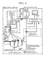
Fig. 4 is an explanatory diagram showing Example 3 of the present invention. -
Fig. 5A is a diagram explaining a positional relationship between a terminal for performance evaluation and plasma when evaluating atmospheric pressure plasma by measuring a current using the terminal for performance evaluation as an treatment target material. -
Fig. 5B is a diagram explaining a positional relationship between a terminal for performance evaluation to be measured along an axis and plasma. - To solve the problems, a plasma evaluation system of the present invention is mainly configured to precisely measure and objectively evaluate a current of an atmospheric pressure plasma and a small current having a low frequency or a high frequency flowing through a living body, etc., by employing a method of measuring a voltage across resistors incorporated on a current path as shown in
Fig. 1 and evaluating a current based on the resistance values and a voltage value, and a method using a Rogowski coil or a current transformer. - The present invention will be specifically explained below based on Examples.
- In the plasma evaluation system, a treatment target material receives plasma generated by a plasma treatment equipment, the treatment target material is connected to a weak current measurement unit including a resistor unit and a differential amplifier via a treatment target side measurement terminal, and the weak current measurement unit is connected to a ground side of a plasma generation power source (PS), as shown in
Fig. 2 . The plasma evaluation system evaluates a current by measuring a voltage across the resistors of the resistor unit through the differential amplifier. It is also possible to measure a change in an output voltage of the plasma generation power source, by using in combination a voltage measurement unit operating based on partial resistance. The ground side of the plasma generation power source is basically grounded, but may be used un-grounded. - The resistors of the resistance unit are variable. Or, the resistance values are switchable. For example, in
Fig. 2 , R1 is in a resistance value range of from 0.1 to about 1 [k·Ω], R2 and R3 are resistance values of about 50 [Ω], and R4 is a resistance value of about 5 [Ω]. - Any electric signal such as an output from the differential amplifier is input as is to an analog-digital (AD) converter such as an oscilloscope, or transmitted through an analog optical converter and an optical fiber in an electrically insulated state, converted to an electric signal at a light receiving unit, and input to an analog-digital converter such as an oscilloscope. An output is displayed on a monitor unit of the oscilloscope. The data may also be connected to a personal computer and displayed on a monitor of the personal computer. The output from the oscilloscope may also be optically converted to be transmitted through an optical fiber in an electrically insulated state, and converted again to an electric signal to be displayed on a personal computer.
- The plasma generation power source is supplied with electricity from a power source such as a DC power source and a battery. A DC power source supplies electricity from an AC line through an isolation transformer. The differential amplifier, the optical converter (from electricity to light; E/O, and from light to electricity; O/E), the oscilloscope, the personal computer, the analog-digital converter, a computing unit, etc. described in the paragraph 0016 are also supplied with electricity from an AC line through an isolation transformer, respectively.
- When the treatment target material shown in
Fig. 2 is a terminal for performance evaluation (A), a current of each plasma treatment equipment is measured for performance evaluation. When the treatment target material is a tray (B), a small-sized animal such as a mouse is put on the tray, and a current is measured from it. When the treatment target material is an examination table (C), a current flowing through a middle-sized animal such as a human being is measured. When the treatment target material is an electrode pad (D), a current flowing through a part of a human body (a hand, a foot, etc.) is measured. Treatment target materials such as A to D described above are provided as option members to be connected to the treatment target side measurement terminal of the evaluation system body. Treatment target materials such as A to D are selected from a metal, an insulating material (a dielectric material), etc. The shape of the terminal for performance evaluation (A) is selected from a flat plate, a sphere, a hemispherical concave, a sharp shape, etc. - By changing the material of the treatment target material among metals, insulating materials (dielectric materials), etc., it is possible to measure currents by taking advantage of electrical discharge characteristics that depend on the electrical characteristics of the respective materials such as the degree of electrical conductivity and the degree of specific permittivity, or their frequency dependency.
- By changing the shape of the treatment target material among a flat plate, a sphere, a hemispherical concave, a sharp shape, etc., it is possible to measure currents by taking advantage of electrical discharge characteristics that depend on the electric field distributions dependent on the respective shapes. For example, of treatment target materials made of the same metal, a treatment target material having a sharp tip is electrically charged intensively at the tip, whereas a treatment target material having a concave surface has an extremely low charge density in the surface. Therefore, it is possible to evaluate plasma of the plasma treatment equipment under different electrical discharge conditions.
- It is also possible to monitor a portion treated with plasma with a visible-range or infrared-range camera and send an output signal to a personal computer or the like to thereby display changes in the current, videos and surface temperature of the treated portion, etc. on a monitor.
- It is also possible to measure a current through a Rogowski coil or a current transformer attached between the output of the resistor unit and the ground side of the plasma generation power source as shown in
Fig. 3 . An output from the Rogowski coil and the current transformer is amplified by an amplifier and input to an analog-digital converter. It is also possible to measure a signal from an amplifier by optically converting it to transmit it through an optical fiber in an electrically insulated state, converting it to an electric signal at a light receiving unit, and inputting the electric signal to an analog-digital converter. Each amplifier is supplied with electricity from an AC line through an isolation transformer. By attaching the Rogowski coil or the current transformer between the plasma generation power source and a voltage application electrode of the plasma treatment equipment or between a ground electrode of the plasma treatment equipment and the ground side of the plasma generation power source, it is possible to measure currents flowing through these positions. - In another configuration, plasma generated by a plasma treatment equipment is received by a treatment target material, and the treatment target material is connected to a ground side of a plasma generation power source via a treatment target side measurement terminal, as shown in
Fig. 4 . A current can be measured through a Rogowski coil or a current transformer attached between the treatment target side measurement terminal and the ground side of the plasma generation power source. - When evaluating the performance of each plasma treatment equipment by measuring a current with Examples 1 to 3 described above, it is possible to suppress noise signals more by installing a power source for the plasma treatment equipment and the components of the plasma evaluation system other than the plasma treatment target material thereof in electromagnetic shield boxes respectively.
- An example of plasma current evaluation will be described. With a signal captured into an analog-digital converter, an oscilloscope, or a personal computer, a state of temporal changes of a current or a voltage is displayed. When the analog-digital converter, the oscilloscope, and the personal computer include a computing function, they can calculate and display the true plasma current component flowed through a living body, etc. by eliminating a displacement current component generated by the plasma generation power source, etc. A specific method is based on the two diagrams described below, including a computing diagram A and a computing diagram B.
-
- (1) Conditions for not generating plasma are set (e.g., when not flowing a gas, the plasma equipment is disconnected from the ground electrode).
Then, a voltage is applied to the plasma treatment equipment, and a voltage value V1 and a current value I1 are measured. - (2) Conditions for generating plasma are set (e.g., a gas is let to flow), and a voltage is applied to the plasma treatment equipment to generate plasma.
- (3) The output of a supply power source is adjusted to obtain a voltage value equal to the voltage value V1 of (1), and a resulting current value I3 is measured.
- (4) The phases of the currents measured in (1) and (3) are adjusted to align the peaks of the currents.
- Then, to obtain a current component that has actually flowed through the living body, etc., the current value I1 of (1) is subtracted from the current value I3 of (3) (i.e., I3-I1). In this way, the current component that has actually flowed through the living body, etc. is calculated.
-
- (1) Conditions for not generating plasma is set (e.g., when not flowing a gas, the plasma equipment is disconnected from the ground electrode).
Then, a voltage is applied to the plasma treatment equipment, and a voltage value V1 and a current value I1 are measured. - (2) Conditions for generating plasma are set (e.g., a gas is let to flow), a voltage is applied to the plasma treatment equipment to generate plasma, and a voltage value V2 and a current value I2 are measured.
- (3) The ratio between the voltage values of (1) and (2) is multiplied by the current of (2), i.e., (V1/V2)×I2.
- Then, to align the peak of the current measured in (1) with this, the phase of the current is adjusted, and I1 is subtracted from this. In this way, a current component that has actually flowed through the living body, etc. is calculated. That is, the current component that has actually flowed through the living body, etc. is calculated from (V1/V2)×I2-I1=V1·I2/V2-I1.
-
Fig. 5A and Fig. 5B are diagrams explaining a plasma evaluation method for evaluating an atmospheric pressure plasma by measuring a current with the plasma evaluation system in which a terminal for performance evaluation is selectively employed as the treatment target material. To develop a method for evaluating a plasma jet, a current of a plasma jet or a weak current flowing in the vicinity thereof during a plasma treatment was examined, and as a result, the following findings were obtained about the relative positional relationship between the plasma jet for atmospheric pressure plasma evaluation based on current measurement and the terminal for performance evaluation. - On the axis of the plasma jet (in a direction L):
- (1) A region from the plasma jet outlet of the plasma treatment equipment up to L0 is within the plasma jet (0≤L1≤L0), and this region is influenced the most by the plasma jet. The plasma treatment is performed within this range. Therefore, this region is the most important for evaluating the plasma.
- (2) A region from the tip of the plasma jet up to a distance of 2L0 (L0<L1≤3L0) is relatively close to the plasma jet extending by a length of L0, and the influence of the plasma jet (a current passed through the plasma jet) cannot be ignored up to this distance. Information of a current in the vicinity of the plasma jet can be obtained from outside the plasma jet.
- (3) When 3L0<L1, the influence of the plasma jet is too small. Therefore, information about the plasma jet cannot be obtained at this position, and this position is not suitable for plasma evaluation. Therefore, on the axis of the plasma jet (in the direction L), the range of 0≤L1≤3L0 is suitable for measurement.
In a direction perpendicular to the axis of the plasma jet (in a direction r), - (4) The plasma jet has a certain diameter, which however is much smaller than L0. Therefore, the plasma jet can be regarded as a line. A region extending from the axis up to 2L0 (0≤r1≤2L0), in which the plasma jet having the length L0 has a large view angle, is a region close to the plasma jet in the direction r, and the influence of the plasma jet (a current passed through the plasma jet) cannot be ignored up to this distance. Information of a current in the vicinity of the plasma jet can be obtained from outside the plasma jet. Since the treatment target terminal for performance evaluation has a size, it may be necessary to shift the direction of the plasma jet to some degree. Even in such a case, the reach of the influence of the plasma jet falls within the range of 0≤r1≤2L0 from the axis.
- In
Fig. 5A and Fig. 5B , a circular columnar region having a radium of L0×2 and a height of L0×3 is assumed (represented by a dotted line in the drawings), where L0 is the length of the plasma generated by the plasma treatment equipment. Plasma treatment is applied along the center axis of the circular column from the center of the upper base of the circular column toward the lower base thereof. In this case, it is possible to evaluate the atmospheric pressure plasma by measuring a current by selecting a measuring position appropriately within the range of the circular columnar region or by shifting the measuring position within the range of the circular columnar region. For example, it is possible to evaluate the optimum state of the plasma treatment equipment, by applying this system to the equipment before use. - For the medical field where a plasma treatment is applied to a living body for the purposes of blood coagulation, blood stanching, etc., an evaluation system is provided, which has a function of monitoring a treatment state when the plasma treatment equipment is used during a plasma treatment, or the performance of the treatment equipment before a treatment or during a treatment.
- Because the plasma evaluation system can measure current values generated by plasma treatment equipment, it is possible, for, for example, medical purposes, to give an evaluation to, for example, take a measure of limiting the output when the current value exceeds a certain value.
- The present invention can easily measure current components generated by various plasma treatment equipments, and can objectively evaluate the difference between the currents of the equipments. Particularly, the present invention is suitable for measuring medical plasma treatment equipments. Further, when a plasma treatment equipment is used on site such as a factory, by objectively evaluating the state of the plasma treatment equipment, it is possible to perform measurement on site, or perform measurement for maintenance, or objectively judge whether the cause of any trouble is attributable to the plasma equipment or to any other factor.
Claims (11)
- A plasma evaluation system, comprising:a treatment target material; anda weak current measurement unit including a resistor unit and a differential amplifier,wherein the treatment target material is connected to the weak current measurement unit via a treatment target side measurement terminal,wherein the resistor unit of the weak current measurement unit is connected to a ground side of a plasma generation power source, andwherein the plasma evaluation system is configured to evaluate plasma by receiving plasma generated by a plasma treatment equipment with the treatment target material, measuring a current of a voltage across resistors of the resistor unit through the differential amplifier, and measuring an output voltage of the plasma generation power source.
- The plasma evaluation system according to claim 1,
wherein the resistors are variable, or resistance values are switchable. - The plasma evaluation system according to claim 1 or 2,
wherein the plasma evaluation system is configured to measure an output signal of the differential amplifier and a signal of a voltage by transmitting the signals through an analog optical converter and an optical fiber, converting the signals to electric signals at a light receiving unit, and inputting the electric signals to an analog-digital converter, or to measure an output signal of the differential amplifier and a signal of a voltage by inputting the signals to an analog-digital converter, further converting the signals to light to thereby transmit the signals through an optical fiber as electrically insulated data, and inputting the signals to another analog-digital converter. - The plasma evaluation system according to any one of claims 1 to 3,
wherein the plasma evaluation system is configured to measure a current of the plasma treatment equipment when the treatment target material is a terminal for performance evaluation, measure a current of a small-sized animal such as a mouse when the treatment target material is a tray, with the small-sized animal on the tray, measure a current flowing through a human being or a middle-sized animal when the treatment target material is an examination table, or measure a current flowing through a part of a human body when the treatment target material is an electrode pad. - The plasma evaluation system according to claim 4,
wherein in measuring any of the currents described in claim 4, the plasma evaluation system is configured to:(A-1) apply a voltage to the plasma treatment equipment under conditions for not generating plasma, and measure a resulting voltage value V1 and a resulting current value I1;(A-2) apply a voltage to the plasma treatment equipment under conditions for generating plasma to generate plasma;(A-3) adjust an output from a supply power source such that a voltage value equal to the voltage value V1 of (A-1) is obtained, and measure a resulting current value I3; and(A-4) adjust phases of the current values measured in (A-1) and (A-3) to align peaks of the current values, subtract the current value I1 of (A-1) from the current value I3 of (A-3), and evaluate a resulting value, which is I3-I1, as a current component that has actually flowed,
or is configured to:(B-1) apply a voltage to the plasma treatment equipment under conditions for not generating plasma, and measure a resulting voltage value V1 and a resulting current value I1;(B-2) apply a voltage to the plasma treatment equipment under conditions for generating plasma to generate plasma, and measure a resulting voltage value V2 and a resulting current value I2; and(B-3) adjust a phase of the current value measured in (B-1) to align a peak of the current value with (V1/V2)×I2, which is obtained by multiplying a ratio between the voltage values of (B-1) and (B-2) by the current value of (B-2), subtract I1 from (V1/V2)×I2, and evaluate a resulting value (V1/V2)×I2-I1, which is V1·I2/V2-I1, as a current component that has actually flowed. - The plasma evaluation system according to any one of claims 1 to 5,
wherein the plasma evaluation system is configured to measure a current through a Rogowski coil or a current transformer attached between an output of the resistor unit and the ground side of the plasma generation power source. - A plasma evaluation system, comprising:a treatment target material connected to a ground side of a plasma generation power source via a treatment target side measurement terminal; anda Rogowski coil or a current transformer attached between the treatment target side measurement terminal and the ground side of the plasma generation power source,wherein the plasma evaluation system is configured to evaluate plasma by receiving plasma generated by a plasma treatment equipment with the treatment target material, measuring a current through the Rogowski coil or the current transformer, and measuring an output voltage of the plasma generation power source, andwherein the plasma evaluation system is configured to measure a current of the plasma treatment equipment when the treatment target material is a terminal for performance evaluation, measure a current of a small-sized animal such as a mouse when the treatment target material is a tray, with the small-sized animal on the tray, measure a current flowing through a human being or a middle-sized animal when the treatment target material is an examination table, or measure a current flowing through a part of a human body when the treatment target material is an electrode pad.
- The plasma evaluation system according to claim 6 or 7,
wherein the plasma evaluation system is configured to measure an output signal of an amplifier of the Rogowski coil or the current transformer by inputting the output signal to an analog-digital converter, or to measure an output signal of the amplifier by transmitting the output signal through an analog optical converter and an optical fiber, converting the output signal to an electric signal at a light receiving unit, and inputting the electric signal to an analog-digital converter, or to measure an output signal of the amplifier by inputting the output signal to an analog-digital converter, further converting the output signal to light to thereby transmit the output signal through an optical fiber as electrically insulated data, and inputting the output signal to another analog-digital converter. - The plasma evaluation system according to any one of claims 1 to 8,
wherein the plasma evaluation system is configured to be used in combination with monitoring with a visible-range or infrared-range camera, to observe a state of a portion treated with plasma. - A plasma evaluation method, comprising:evaluating atmospheric pressure plasma by measuring a current with the plasma evaluation system according to any one of claims 1 to 9.
- A plasma evaluation method for evaluating atmospheric pressure plasma by measuring a current beforehand with the plasma evaluation system according to any one of claims 1 to 9 in which a terminal for performance evaluation is selected as the treatment target material, the method comprising:evaluating atmospheric pressure plasma by measuring a current within a range in which a relative position of the terminal for performance evaluation with respect to the plasma is within an imaginary circular columnar region having a radius of L0×2 and a height of L0×3, wherein L0 is a length of the plasma generated by a plasma treatment equipment, and plasma treatment is applied along a center axis of the circular columnar region from a center of an upper base of the circular columnar region toward a lower base thereof.
Applications Claiming Priority (2)
| Application Number | Priority Date | Filing Date | Title |
|---|---|---|---|
| JP2011254516 | 2011-11-22 | ||
| PCT/JP2012/077258 WO2013077126A1 (en) | 2011-11-22 | 2012-10-22 | Plasma evaluation apparatus |
Publications (3)
| Publication Number | Publication Date |
|---|---|
| EP2782430A1 true EP2782430A1 (en) | 2014-09-24 |
| EP2782430A4 EP2782430A4 (en) | 2015-07-01 |
| EP2782430B1 EP2782430B1 (en) | 2016-08-03 |
Family
ID=48469577
Family Applications (1)
| Application Number | Title | Priority Date | Filing Date |
|---|---|---|---|
| EP12851481.7A Not-in-force EP2782430B1 (en) | 2011-11-22 | 2012-10-22 | Plasma evaluation apparatus |
Country Status (4)
| Country | Link |
|---|---|
| US (1) | US9254397B2 (en) |
| EP (1) | EP2782430B1 (en) |
| JP (1) | JP6074792B2 (en) |
| WO (1) | WO2013077126A1 (en) |
Families Citing this family (4)
| Publication number | Priority date | Publication date | Assignee | Title |
|---|---|---|---|---|
| JP6399852B2 (en) * | 2014-08-07 | 2018-10-03 | フクダ電子株式会社 | Pulse wave measuring device and biological information measuring device |
| US9711252B1 (en) * | 2014-10-28 | 2017-07-18 | Michelle Corning | High energy beam diffraction material treatment system |
| JP6664046B2 (en) * | 2016-03-07 | 2020-03-13 | 国立研究開発法人産業技術総合研究所 | Plasma irradiation processing apparatus, evaluation apparatus and evaluation method thereof, control apparatus and control method thereof, and method of manufacturing film |
| EP3457820B1 (en) * | 2016-05-13 | 2020-10-14 | Fuji Corporation | Medical plasma-generating device |
Family Cites Families (14)
| Publication number | Priority date | Publication date | Assignee | Title |
|---|---|---|---|---|
| JPS59135474U (en) * | 1983-02-28 | 1984-09-10 | 富士通株式会社 | current measuring device |
| JP3149272B2 (en) * | 1991-12-10 | 2001-03-26 | 幸子 岡崎 | How to monitor atmospheric pressure glow discharge plasma |
| JP3085560B2 (en) | 1992-08-26 | 2000-09-11 | 株式会社日立製作所 | Fusion device and its plasma control method and control device |
| CA2194072C (en) | 1994-06-27 | 2005-12-13 | Roger A. Stern | Tissue heating and ablation system |
| US5735846A (en) | 1994-06-27 | 1998-04-07 | Ep Technologies, Inc. | Systems and methods for ablating body tissue using predicted maximum tissue temperature |
| JP3068052B2 (en) * | 1998-04-06 | 2000-07-24 | 株式会社メックス | Electrosurgical equipment |
| DE19839826A1 (en) * | 1998-09-01 | 2000-03-02 | Karl Fastenmeier | High-frequency device for generating a plasma arc for the treatment of human tissue |
| JP4242737B2 (en) * | 2003-09-02 | 2009-03-25 | ナノフォトン株式会社 | Laser treatment apparatus and cell destruction method |
| JP2005147125A (en) * | 2003-10-20 | 2005-06-09 | Toyota Motor Corp | Power supply circuit for plasma reactor |
| JP3957705B2 (en) | 2004-05-28 | 2007-08-15 | 株式会社半導体理工学研究センター | Plasma processing equipment |
| WO2006107044A1 (en) * | 2005-04-04 | 2006-10-12 | Matsushita Electric Industrial Co., Ltd. | Plasma processing method and system |
| JP4752073B2 (en) * | 2006-01-20 | 2011-08-17 | 国立大学法人九州大学 | Method for solubilizing carbon nanomaterials |
| DE102009011960B4 (en) * | 2009-03-10 | 2013-06-13 | Schott Ag | Method for monitoring plasma discharges |
| EP2591742A4 (en) | 2010-07-07 | 2018-01-03 | National Institute of Advanced Industrial Science And Technology | Plasma irradiation treatment device |
-
2012
- 2012-10-22 WO PCT/JP2012/077258 patent/WO2013077126A1/en not_active Ceased
- 2012-10-22 EP EP12851481.7A patent/EP2782430B1/en not_active Not-in-force
- 2012-10-22 US US14/359,970 patent/US9254397B2/en active Active
- 2012-10-24 JP JP2012234839A patent/JP6074792B2/en not_active Expired - Fee Related
Also Published As
| Publication number | Publication date |
|---|---|
| JP2013131487A (en) | 2013-07-04 |
| WO2013077126A1 (en) | 2013-05-30 |
| US9254397B2 (en) | 2016-02-09 |
| EP2782430A4 (en) | 2015-07-01 |
| US20140312241A1 (en) | 2014-10-23 |
| JP6074792B2 (en) | 2017-02-08 |
| EP2782430B1 (en) | 2016-08-03 |
Similar Documents
| Publication | Publication Date | Title |
|---|---|---|
| EP2782430B1 (en) | Plasma evaluation apparatus | |
| Litvak et al. | Experimental studies of high-frequency azimuthal waves in Hall thrusters | |
| EP2436326B1 (en) | Real-time ARC control in electrosurgical generators | |
| AU2011202512B2 (en) | System and method for sensing tissue characteristics | |
| JP2021177775A (en) | High voltage analog circuit pulsar with feedback control | |
| JP2014010152A (en) | System and method for measuring frequency of signal generated by device for high frequency medical treatment | |
| TW201233252A (en) | Measuring and controlling parameters of a plasma generator | |
| KR20130083350A (en) | Bio-impedance measuring sensor comprising multi dry electrode, and sensor module and measuring system comprising the same, and method for measuring bio-impedance | |
| CN101933404A (en) | Diagnostic method and apparatus for accelerators using inductance for generating electric fields with local curl | |
| CN106443237B (en) | The test method and device of the high and low pressure system isolation of electric car | |
| EP3912583B1 (en) | Testing electrode quality | |
| Kim et al. | Wireless electric field sensor with adaptive voltage gain for measuring an electrical potential treatment chair | |
| JP2014535129A (en) | Control module for ion implanter | |
| US20230305045A1 (en) | System and method for non-invasive sensing of radio-frequency current spectra flowing in a plasma processing chamber | |
| TWI794845B (en) | A semiconductor device with state-controlled radio frequency system | |
| Sibanyoni et al. | Sensitivity of the electrical and UV imaging methods for corona detection under HVDC application | |
| CZ2011890A3 (en) | Method of measuring ionic distribution function in a low-temperature plasma, measuring system for making the method and a probe for such measuring system | |
| CZ33034U1 (en) | Device for measuring the mass of ions in low temperature plasma | |
| Haller et al. | Short-and longtime stability of therapeutic ultrasound reference sources for dosimetry and exposimetry purposes | |
| Mazurek et al. | Analysis of electrical and magnetic fields in ELF band from plasma reactor installations | |
| Li et al. | Optimization of a self-integrating pcb rogowski coil for discharge plasma current detection | |
| US20240053385A1 (en) | Eeg impedance test circuit, method, and device | |
| US12414833B2 (en) | Test device | |
| CZ23356U1 (en) | Measuring system to measure ion distribution function in low-temperature plasma and probe for such measuring system d | |
| CN216929684U (en) | Electric energy quality regulating switch |
Legal Events
| Date | Code | Title | Description |
|---|---|---|---|
| PUAI | Public reference made under article 153(3) epc to a published international application that has entered the european phase |
Free format text: ORIGINAL CODE: 0009012 |
|
| 17P | Request for examination filed |
Effective date: 20140619 |
|
| AK | Designated contracting states |
Kind code of ref document: A1 Designated state(s): AL AT BE BG CH CY CZ DE DK EE ES FI FR GB GR HR HU IE IS IT LI LT LU LV MC MK MT NL NO PL PT RO RS SE SI SK SM TR |
|
| DAX | Request for extension of the european patent (deleted) | ||
| RA4 | Supplementary search report drawn up and despatched (corrected) |
Effective date: 20150529 |
|
| RIC1 | Information provided on ipc code assigned before grant |
Ipc: A61B 17/00 20060101ALN20150522BHEP Ipc: H05H 1/46 20060101ALI20150522BHEP Ipc: A61B 18/04 20060101ALI20150522BHEP Ipc: H05H 1/00 20060101AFI20150522BHEP Ipc: A61B 18/00 20060101ALN20150522BHEP |
|
| RIC1 | Information provided on ipc code assigned before grant |
Ipc: A61B 17/00 20060101ALN20151130BHEP Ipc: H05H 1/46 20060101ALI20151130BHEP Ipc: H05H 1/00 20060101AFI20151130BHEP Ipc: A61B 18/04 20060101ALI20151130BHEP Ipc: A61B 18/00 20060101ALN20151130BHEP |
|
| GRAP | Despatch of communication of intention to grant a patent |
Free format text: ORIGINAL CODE: EPIDOSNIGR1 |
|
| INTG | Intention to grant announced |
Effective date: 20160120 |
|
| GRAR | Information related to intention to grant a patent recorded |
Free format text: ORIGINAL CODE: EPIDOSNIGR71 |
|
| GRAS | Grant fee paid |
Free format text: ORIGINAL CODE: EPIDOSNIGR3 |
|
| GRAA | (expected) grant |
Free format text: ORIGINAL CODE: 0009210 |
|
| RIC1 | Information provided on ipc code assigned before grant |
Ipc: H05H 1/46 20060101ALI20160530BHEP Ipc: H05H 1/00 20060101AFI20160530BHEP Ipc: A61B 17/00 20060101ALN20160530BHEP Ipc: A61B 18/00 20060101ALN20160530BHEP Ipc: A61B 18/04 20060101ALI20160530BHEP |
|
| INTG | Intention to grant announced |
Effective date: 20160622 |
|
| AK | Designated contracting states |
Kind code of ref document: B1 Designated state(s): AL AT BE BG CH CY CZ DE DK EE ES FI FR GB GR HR HU IE IS IT LI LT LU LV MC MK MT NL NO PL PT RO RS SE SI SK SM TR |
|
| REG | Reference to a national code |
Ref country code: GB Ref legal event code: FG4D |
|
| REG | Reference to a national code |
Ref country code: CH Ref legal event code: EP Ref country code: AT Ref legal event code: REF Ref document number: 818051 Country of ref document: AT Kind code of ref document: T Effective date: 20160815 |
|
| REG | Reference to a national code |
Ref country code: IE Ref legal event code: FG4D |
|
| REG | Reference to a national code |
Ref country code: DE Ref legal event code: R096 Ref document number: 602012021320 Country of ref document: DE |
|
| REG | Reference to a national code |
Ref country code: NL Ref legal event code: MP Effective date: 20160803 |
|
| REG | Reference to a national code |
Ref country code: LT Ref legal event code: MG4D |
|
| REG | Reference to a national code |
Ref country code: AT Ref legal event code: MK05 Ref document number: 818051 Country of ref document: AT Kind code of ref document: T Effective date: 20160803 |
|
| PG25 | Lapsed in a contracting state [announced via postgrant information from national office to epo] |
Ref country code: RS Free format text: LAPSE BECAUSE OF FAILURE TO SUBMIT A TRANSLATION OF THE DESCRIPTION OR TO PAY THE FEE WITHIN THE PRESCRIBED TIME-LIMIT Effective date: 20160803 Ref country code: HR Free format text: LAPSE BECAUSE OF FAILURE TO SUBMIT A TRANSLATION OF THE DESCRIPTION OR TO PAY THE FEE WITHIN THE PRESCRIBED TIME-LIMIT Effective date: 20160803 Ref country code: NO Free format text: LAPSE BECAUSE OF FAILURE TO SUBMIT A TRANSLATION OF THE DESCRIPTION OR TO PAY THE FEE WITHIN THE PRESCRIBED TIME-LIMIT Effective date: 20161103 Ref country code: FI Free format text: LAPSE BECAUSE OF FAILURE TO SUBMIT A TRANSLATION OF THE DESCRIPTION OR TO PAY THE FEE WITHIN THE PRESCRIBED TIME-LIMIT Effective date: 20160803 Ref country code: IS Free format text: LAPSE BECAUSE OF FAILURE TO SUBMIT A TRANSLATION OF THE DESCRIPTION OR TO PAY THE FEE WITHIN THE PRESCRIBED TIME-LIMIT Effective date: 20161203 Ref country code: NL Free format text: LAPSE BECAUSE OF FAILURE TO SUBMIT A TRANSLATION OF THE DESCRIPTION OR TO PAY THE FEE WITHIN THE PRESCRIBED TIME-LIMIT Effective date: 20160803 Ref country code: LT Free format text: LAPSE BECAUSE OF FAILURE TO SUBMIT A TRANSLATION OF THE DESCRIPTION OR TO PAY THE FEE WITHIN THE PRESCRIBED TIME-LIMIT Effective date: 20160803 Ref country code: IT Free format text: LAPSE BECAUSE OF FAILURE TO SUBMIT A TRANSLATION OF THE DESCRIPTION OR TO PAY THE FEE WITHIN THE PRESCRIBED TIME-LIMIT Effective date: 20160803 |
|
| PG25 | Lapsed in a contracting state [announced via postgrant information from national office to epo] |
Ref country code: PL Free format text: LAPSE BECAUSE OF FAILURE TO SUBMIT A TRANSLATION OF THE DESCRIPTION OR TO PAY THE FEE WITHIN THE PRESCRIBED TIME-LIMIT Effective date: 20160803 Ref country code: AT Free format text: LAPSE BECAUSE OF FAILURE TO SUBMIT A TRANSLATION OF THE DESCRIPTION OR TO PAY THE FEE WITHIN THE PRESCRIBED TIME-LIMIT Effective date: 20160803 Ref country code: ES Free format text: LAPSE BECAUSE OF FAILURE TO SUBMIT A TRANSLATION OF THE DESCRIPTION OR TO PAY THE FEE WITHIN THE PRESCRIBED TIME-LIMIT Effective date: 20160803 Ref country code: BE Free format text: LAPSE BECAUSE OF NON-PAYMENT OF DUE FEES Effective date: 20161031 Ref country code: SE Free format text: LAPSE BECAUSE OF FAILURE TO SUBMIT A TRANSLATION OF THE DESCRIPTION OR TO PAY THE FEE WITHIN THE PRESCRIBED TIME-LIMIT Effective date: 20160803 Ref country code: LV Free format text: LAPSE BECAUSE OF FAILURE TO SUBMIT A TRANSLATION OF THE DESCRIPTION OR TO PAY THE FEE WITHIN THE PRESCRIBED TIME-LIMIT Effective date: 20160803 Ref country code: GR Free format text: LAPSE BECAUSE OF FAILURE TO SUBMIT A TRANSLATION OF THE DESCRIPTION OR TO PAY THE FEE WITHIN THE PRESCRIBED TIME-LIMIT Effective date: 20161104 Ref country code: PT Free format text: LAPSE BECAUSE OF FAILURE TO SUBMIT A TRANSLATION OF THE DESCRIPTION OR TO PAY THE FEE WITHIN THE PRESCRIBED TIME-LIMIT Effective date: 20161205 |
|
| PG25 | Lapsed in a contracting state [announced via postgrant information from national office to epo] |
Ref country code: EE Free format text: LAPSE BECAUSE OF FAILURE TO SUBMIT A TRANSLATION OF THE DESCRIPTION OR TO PAY THE FEE WITHIN THE PRESCRIBED TIME-LIMIT Effective date: 20160803 Ref country code: RO Free format text: LAPSE BECAUSE OF FAILURE TO SUBMIT A TRANSLATION OF THE DESCRIPTION OR TO PAY THE FEE WITHIN THE PRESCRIBED TIME-LIMIT Effective date: 20160803 |
|
| REG | Reference to a national code |
Ref country code: DE Ref legal event code: R097 Ref document number: 602012021320 Country of ref document: DE |
|
| PG25 | Lapsed in a contracting state [announced via postgrant information from national office to epo] |
Ref country code: BG Free format text: LAPSE BECAUSE OF FAILURE TO SUBMIT A TRANSLATION OF THE DESCRIPTION OR TO PAY THE FEE WITHIN THE PRESCRIBED TIME-LIMIT Effective date: 20161103 Ref country code: SM Free format text: LAPSE BECAUSE OF FAILURE TO SUBMIT A TRANSLATION OF THE DESCRIPTION OR TO PAY THE FEE WITHIN THE PRESCRIBED TIME-LIMIT Effective date: 20160803 Ref country code: BE Free format text: LAPSE BECAUSE OF FAILURE TO SUBMIT A TRANSLATION OF THE DESCRIPTION OR TO PAY THE FEE WITHIN THE PRESCRIBED TIME-LIMIT Effective date: 20160803 Ref country code: DK Free format text: LAPSE BECAUSE OF FAILURE TO SUBMIT A TRANSLATION OF THE DESCRIPTION OR TO PAY THE FEE WITHIN THE PRESCRIBED TIME-LIMIT Effective date: 20160803 Ref country code: CZ Free format text: LAPSE BECAUSE OF FAILURE TO SUBMIT A TRANSLATION OF THE DESCRIPTION OR TO PAY THE FEE WITHIN THE PRESCRIBED TIME-LIMIT Effective date: 20160803 Ref country code: SK Free format text: LAPSE BECAUSE OF FAILURE TO SUBMIT A TRANSLATION OF THE DESCRIPTION OR TO PAY THE FEE WITHIN THE PRESCRIBED TIME-LIMIT Effective date: 20160803 |
|
| REG | Reference to a national code |
Ref country code: CH Ref legal event code: PL |
|
| PLBE | No opposition filed within time limit |
Free format text: ORIGINAL CODE: 0009261 |
|
| STAA | Information on the status of an ep patent application or granted ep patent |
Free format text: STATUS: NO OPPOSITION FILED WITHIN TIME LIMIT |
|
| 26N | No opposition filed |
Effective date: 20170504 |
|
| GBPC | Gb: european patent ceased through non-payment of renewal fee |
Effective date: 20161103 |
|
| REG | Reference to a national code |
Ref country code: IE Ref legal event code: MM4A |
|
| REG | Reference to a national code |
Ref country code: FR Ref legal event code: ST Effective date: 20170630 |
|
| PG25 | Lapsed in a contracting state [announced via postgrant information from national office to epo] |
Ref country code: CH Free format text: LAPSE BECAUSE OF NON-PAYMENT OF DUE FEES Effective date: 20161031 Ref country code: LI Free format text: LAPSE BECAUSE OF NON-PAYMENT OF DUE FEES Effective date: 20161031 Ref country code: FR Free format text: LAPSE BECAUSE OF NON-PAYMENT OF DUE FEES Effective date: 20161102 |
|
| PG25 | Lapsed in a contracting state [announced via postgrant information from national office to epo] |
Ref country code: LU Free format text: LAPSE BECAUSE OF NON-PAYMENT OF DUE FEES Effective date: 20161022 Ref country code: SI Free format text: LAPSE BECAUSE OF FAILURE TO SUBMIT A TRANSLATION OF THE DESCRIPTION OR TO PAY THE FEE WITHIN THE PRESCRIBED TIME-LIMIT Effective date: 20160803 |
|
| PG25 | Lapsed in a contracting state [announced via postgrant information from national office to epo] |
Ref country code: IE Free format text: LAPSE BECAUSE OF NON-PAYMENT OF DUE FEES Effective date: 20161022 Ref country code: GB Free format text: LAPSE BECAUSE OF NON-PAYMENT OF DUE FEES Effective date: 20161103 |
|
| PG25 | Lapsed in a contracting state [announced via postgrant information from national office to epo] |
Ref country code: HU Free format text: LAPSE BECAUSE OF FAILURE TO SUBMIT A TRANSLATION OF THE DESCRIPTION OR TO PAY THE FEE WITHIN THE PRESCRIBED TIME-LIMIT; INVALID AB INITIO Effective date: 20121022 |
|
| PG25 | Lapsed in a contracting state [announced via postgrant information from national office to epo] |
Ref country code: MC Free format text: LAPSE BECAUSE OF FAILURE TO SUBMIT A TRANSLATION OF THE DESCRIPTION OR TO PAY THE FEE WITHIN THE PRESCRIBED TIME-LIMIT Effective date: 20160803 Ref country code: MK Free format text: LAPSE BECAUSE OF FAILURE TO SUBMIT A TRANSLATION OF THE DESCRIPTION OR TO PAY THE FEE WITHIN THE PRESCRIBED TIME-LIMIT Effective date: 20160803 Ref country code: MT Free format text: LAPSE BECAUSE OF NON-PAYMENT OF DUE FEES Effective date: 20161031 Ref country code: CY Free format text: LAPSE BECAUSE OF FAILURE TO SUBMIT A TRANSLATION OF THE DESCRIPTION OR TO PAY THE FEE WITHIN THE PRESCRIBED TIME-LIMIT Effective date: 20160803 |
|
| PG25 | Lapsed in a contracting state [announced via postgrant information from national office to epo] |
Ref country code: AL Free format text: LAPSE BECAUSE OF FAILURE TO SUBMIT A TRANSLATION OF THE DESCRIPTION OR TO PAY THE FEE WITHIN THE PRESCRIBED TIME-LIMIT Effective date: 20160803 Ref country code: TR Free format text: LAPSE BECAUSE OF FAILURE TO SUBMIT A TRANSLATION OF THE DESCRIPTION OR TO PAY THE FEE WITHIN THE PRESCRIBED TIME-LIMIT Effective date: 20160803 |
|
| REG | Reference to a national code |
Ref country code: DE Ref legal event code: R082 Ref document number: 602012021320 Country of ref document: DE Representative=s name: PAGE, WHITE & FARRER GERMANY LLP, DE |
|
| PGFP | Annual fee paid to national office [announced via postgrant information from national office to epo] |
Ref country code: DE Payment date: 20210820 Year of fee payment: 10 |
|
| REG | Reference to a national code |
Ref country code: DE Ref legal event code: R119 Ref document number: 602012021320 Country of ref document: DE |
|
| PG25 | Lapsed in a contracting state [announced via postgrant information from national office to epo] |
Ref country code: DE Free format text: LAPSE BECAUSE OF NON-PAYMENT OF DUE FEES Effective date: 20230503 |