EP2782226A2 - Flux controlled PM electric machine rotor - Google Patents
Flux controlled PM electric machine rotor Download PDFInfo
- Publication number
- EP2782226A2 EP2782226A2 EP14160723.4A EP14160723A EP2782226A2 EP 2782226 A2 EP2782226 A2 EP 2782226A2 EP 14160723 A EP14160723 A EP 14160723A EP 2782226 A2 EP2782226 A2 EP 2782226A2
- Authority
- EP
- European Patent Office
- Prior art keywords
- flux
- permanent magnets
- rotor
- current
- pmm
- Prior art date
- Legal status (The legal status is an assumption and is not a legal conclusion. Google has not performed a legal analysis and makes no representation as to the accuracy of the status listed.)
- Granted
Links
Images


Classifications
-
- H—ELECTRICITY
- H02—GENERATION; CONVERSION OR DISTRIBUTION OF ELECTRIC POWER
- H02K—DYNAMO-ELECTRIC MACHINES
- H02K21/00—Synchronous motors having permanent magnets; Synchronous generators having permanent magnets
- H02K21/02—Details
- H02K21/04—Windings on magnets for additional excitation ; Windings and magnets for additional excitation
- H02K21/042—Windings on magnets for additional excitation ; Windings and magnets for additional excitation with permanent magnets and field winding both rotating
-
- H—ELECTRICITY
- H02—GENERATION; CONVERSION OR DISTRIBUTION OF ELECTRIC POWER
- H02K—DYNAMO-ELECTRIC MACHINES
- H02K19/00—Synchronous motors or generators
- H02K19/16—Synchronous generators
- H02K19/26—Synchronous generators characterised by the arrangement of exciting windings
- H02K19/28—Synchronous generators characterised by the arrangement of exciting windings for self-excitation
-
- H—ELECTRICITY
- H02—GENERATION; CONVERSION OR DISTRIBUTION OF ELECTRIC POWER
- H02P—CONTROL OR REGULATION OF ELECTRIC MOTORS, ELECTRIC GENERATORS OR DYNAMO-ELECTRIC CONVERTERS; CONTROLLING TRANSFORMERS, REACTORS OR CHOKE COILS
- H02P25/00—Arrangements or methods for the control of AC motors characterised by the kind of AC motor or by structural details
- H02P25/16—Arrangements or methods for the control of AC motors characterised by the kind of AC motor or by structural details characterised by the circuit arrangement or by the kind of wiring
- H02P25/28—Arrangements or methods for the control of AC motors characterised by the kind of AC motor or by structural details characterised by the circuit arrangement or by the kind of wiring using magnetic devices with controllable degree of saturation, e.g. transductors
-
- H—ELECTRICITY
- H02—GENERATION; CONVERSION OR DISTRIBUTION OF ELECTRIC POWER
- H02P—CONTROL OR REGULATION OF ELECTRIC MOTORS, ELECTRIC GENERATORS OR DYNAMO-ELECTRIC CONVERTERS; CONTROLLING TRANSFORMERS, REACTORS OR CHOKE COILS
- H02P9/00—Arrangements for controlling electric generators for the purpose of obtaining a desired output
- H02P9/14—Arrangements for controlling electric generators for the purpose of obtaining a desired output by variation of field
- H02P9/26—Arrangements for controlling electric generators for the purpose of obtaining a desired output by variation of field using discharge tubes or semiconductor devices
- H02P9/30—Arrangements for controlling electric generators for the purpose of obtaining a desired output by variation of field using discharge tubes or semiconductor devices using semiconductor devices
- H02P9/302—Brushless excitation
-
- H—ELECTRICITY
- H02—GENERATION; CONVERSION OR DISTRIBUTION OF ELECTRIC POWER
- H02P—CONTROL OR REGULATION OF ELECTRIC MOTORS, ELECTRIC GENERATORS OR DYNAMO-ELECTRIC CONVERTERS; CONTROLLING TRANSFORMERS, REACTORS OR CHOKE COILS
- H02P9/00—Arrangements for controlling electric generators for the purpose of obtaining a desired output
- H02P9/40—Arrangements for controlling electric generators for the purpose of obtaining a desired output by variation of reluctance of magnetic circuit of generator
-
- H—ELECTRICITY
- H02—GENERATION; CONVERSION OR DISTRIBUTION OF ELECTRIC POWER
- H02P—CONTROL OR REGULATION OF ELECTRIC MOTORS, ELECTRIC GENERATORS OR DYNAMO-ELECTRIC CONVERTERS; CONTROLLING TRANSFORMERS, REACTORS OR CHOKE COILS
- H02P2207/00—Indexing scheme relating to controlling arrangements characterised by the type of motor
- H02P2207/05—Synchronous machines, e.g. with permanent magnets or DC excitation
- H02P2207/055—Surface mounted magnet motors
Definitions
- the present invention is related to electric machines, and in particular to electric machines utilizing a flux-regulated permanent magnet rotor.
- generators convert mechanical energy to electrical energy via the interaction of rotating magnetic fields and coils of wire
- motors convert electrical energy to mechanical energy via the interaction of magnetic fields.
- An electric machine may therefore operate as either a generator or a motor depending on the direction of power flow (e.g., mechanical to electrical or electrical to mechanical).
- a multitude of electric machine architectures have been developed with various means of providing interaction between magnetic fields and coils of wire.
- a permanent magnet machine operating in a generating mode, utilizes permanent magnets to generate a constant magnetic field, which is rotated via the mechanical energy supplied by a prime mover such that the rotating magnetic field interacts with the stator coils to provide an output voltage.
- Another type of electric machine again operating in a generating mode, supplies current through a coil to generate the desired magnetic field on the rotor, which is rotated via the mechanical energy supplied by a prime mover, such that a rotating magnetic field is created that interacts with the stationary stator coils to provide an output voltage.
- the output voltage supplied by the PMG depends only on the magnitude of the mechanical energy supplied by the prime mover.
- the output voltage of the generator can be regulated by varying the current supplied to the exciter coil.
- the latter example known as a wound field synchronous machine, is widely utilized.
- permanent magnets offer advantages over excitation provided via an exciter winding, including improved efficiency over more traditional wound field synchronous machines.
- the key drawback to permanent magnets is that magnetic flux provided by the permanent magnets is constant, unlike an exciter coil in which the magnetic flux can be regulated by increasing or decreasing the current through the exciter coil. Permanent magnets would therefore be useful in a number of generator applications if a form of regulation could be introduced.
- a flux-regulated permanent magnet machine includes a stationary portion and a rotating portion.
- the stationary portion includes a plurality of stator/armature windings.
- the rotating portion includes a plurality of permanent magnets and a control/field winding that is supplied with current to control the magnetic flux presented to the stator/armature windings.
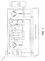
- FIG. 1 is a circuit diagram of electric system 10 according to an embodiment of the present invention.
- System 10 includes permanent magnet machine (PMM) 12, excitation controller 14, and AC input/output 16.
- PMM 12 is divided into stationary portion 18 and rotating portion 20.
- Stationary portion 20 includes stator exciter 22 and stator armature windings 24.
- Rotating portion 20 includes exciter armature windings 26, rotating rectifier 28, DC link 30, DC link capacitor C DC and hybrid permanent magnet (PM) rotor 32, which includes main field winding 34 and main field permanent magnets 36.
- PMM permanent magnet machine
- PMM 12 is divided into stationary portion 18 and rotating portion 20.
- Stationary portion 20 includes stator exciter 22 and stator armature windings 24.
- Rotating portion 20 includes exciter armature windings 26, rotating rectifier 28, DC link 30, DC link capacitor C DC and hybrid permanent magnet (PM) rotor 32, which includes main field winding 34 and main field permanent magnets 36.
- PMM 12 may operate in either a generating mode or a motoring mode.
- generating mode rotational energy supplied to rotating portion 20 is converted to electrical energy provided at main armature windings 24 for supply to AC input/output 16.
- motoring mode electrical energy supplied by AC input/output 16 to main armature winding 24 creates a rotating magnetic field that interacts with the magnetic field provided by hybrid permanent magnet rotor 32 to generate rotation (i.e., mechanical energy) in rotating portion 20.
- the AC output voltage induced in main armature winding 24 in the generating mode is a function, at least in part, of the magnetic flux provided by hybrid permanent magnet rotor 32 to armature winding 24. Increasing the magnetic flux increases the voltage provided by main armature winding 24, while decreasing the magnetic flux decreases the voltage provided by main armature winding 24.
- Permanent magnets 36 included as part of hybrid permanent magnet rotor 32 provide a fixed amount of flux. However, the flux that is provided to main armature windings 24 can be increased or decreased by increasing and/or decreasing (depending on the particular configuration of hybrid PM rotor 32) the current through main field winding 34.
- the voltage (and therefore the current) provided to main field winding 34 can either be regulated or unregulated.
- the voltage provided to main field winding 34 is regulated by regulating the flux provided by stator exciter 22 to exciter armature winding 26, thereby regulating the voltage induced on exciter armature winding 26 and the voltage supplied, via rotating rectifier 28 and DC link bus 30, to main field winding 34.
- stator exciter 22 is implemented with a stator exciter winding through which a variable current is provided by excitation controller 14 to increase or decrease the flux provided by stator exciter 22 to exciter armature winding 26.
- the output voltage of PMM 12 (provided at the output of main armature winding 24) can be regulated by controller 14 selectively increasing/decreasing the current supplied to stator exciter 22.
- PMM 12 is unregulated.
- stator exciter 22 is implemented with a permanent magnet that provides a flux to exciter armature winding 26 that varies only with speed of rotating portion 18.
- the voltage generated by exciter armature windings 26 increases with rotor speed.
- the current supplied to main field winding 34 increases with rotor speed.
- the flux presented to main armature winding decreases, thereby providing automatic voltage regulation (i.e., voltage limiting) of the output provided by PMM 12.
- the electrical energy converted to rotational energy by PMM 12 is a function of the AC current supplied to main armature winding 34 and the magnetic flux provided by hybrid permanent magnet rotor 32.
- Permanent magnet 36 provides a fixed magnitude magnetic flux, which is one of the reasons permanent magnet machines are so efficient over wound-field counterparts.
- BEMF back electromotive force
- main armature windings 24 offsets additional gains in speed that could be obtained by increasing the voltage supplied to main armature winding 24.
- decreasing the magnetic flux provided by hybrid PM rotor 32 in what is called field-weakening, allows the speed of rotating portion 20 to be further increased.
- the voltage (and therefore the current) provided to main field winding 34 can either be regulated or unregulated.
- the voltage provided to main field winding 34 is regulated by regulating the flux provided by stator exciter 22 to exciter armature winding 26, thereby regulating the voltage induced on exciter armature winding 26 and the voltage supplied, via rotating rectifier 28 and DC link bus 30 to main field exciter winding 34.
- stator exciter 22 is implemented with a stator exciter winding through which a variable current is provided by excitation controller 14 to increase or decrease the flux provided by stator exciter 22 to exciter armature winding 26.
- the magnetic flux presented to main armature winding 24 can be regulated by controller 14 to selectively increase/decrease the current supplied to stator exciter 22.
- PMM 12 is unregulated.
- stator exciter 22 is implemented with a permanent magnet that provides a flux to exciter armature winding 26 that only varies with speed of rotating portion 18.
- the voltage generated by exciter armature windings 26 increases with rotor speed.
- the current supplied to main field winding 34 increases with rotor speed.
- the flux presented to main armature winding increases, thereby providing automatic field weakening at higher rotor speeds.
- Fig. 2 is an end view of PMM 40 that illustrates the interaction between hybrid PMM rotor 42 and main armature winding 48.
- stationary portion 43 includes stator yoke 44, a plurality of poles 46, and main armature windings 48.
- Hybrid PMM rotor 42 includes rotor yoke 52, a plurality of permanent magnets 54, and main field winding 56. Voltage is developed in main armature windings 48 in response to changing magnetic flux presented by hybrid PMM rotor 42 in generating mode. Current supplied to main armature windings 48 generates a magnetic field that interacts with the magnetic flux presented by hybrid PMM rotor 42 to provide rotational energy to the rotor portion in the motoring mode.
- rotor yoke 52 is comprised of a magnetically permeable material.
- Rotor yoke 52 may comprise a plurality of laminations stacked adjacent to one another in an axial direction (i.e., into the page), solid metal and/or powder metal pressed into the desired shape.
- the plurality of permanent magnets 54 are mounted to an exterior surface of rotor yoke 52 that is nearest to main armature winding 46. Magnetic flux flows between magnetic poles of opposite polarity.
- Rotor yoke 52 provides a magnetic circuit path through which magnetic flux is allowed to flow when no current is provided to main field winding 56.
- main field winding 56 By increasing the current through main field winding 56, the laminations making up rotor yoke 52 become saturated and the magnetic flux that normally flows between adjacent permanent magnets 54 is prohibited from efficiently completing the magnetic circuit. As a result, when rotor yoke 52 is saturated, less magnetic flux is presented to main armature windings 48.
- the output voltage generated by the plurality of main armature windings 48 is maximized when no current is provided to main field winding 56. Conversely, output voltage is reduced by increasing the current through main field winding 56 to saturate the laminations making up rotor yoke 52, thereby reducing the magnetic flux presented to main armature windings 46.
- the current through main field winding 56 may be regulated or unregulated.
- the current through main field winding 56 is controlled to selectively regulate the flux presented to main armature windings 48, thereby regulating the output voltage generated in main armature windings 48.
- stator exciter 22 may be implemented with permanent magnets that generate a voltage in exciter armature windings 26 (shown in Fig. 1 ) that increase with increasing speed of the PMM. In the context of Fig.
- main field winding 56 increases, thereby allowing current to develop in main field winding 56 that saturates rotor laminations making up rotor yoke 52.
- main armature windings 48 is decreased, providing automatic field weakening at higher rotor speeds.
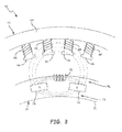
- Fig. 3 is an end view of PMM 60 that illustrates the interaction between hybrid PMM rotor 62 and main armature winding 68.
- stationary portion 63 includes stator yoke 64, a plurality of poles 66, and main armature windings 68.
- Hybrid PMM rotor 62 includes rotor 72, a plurality of permanent magnets 74, and main field winding 76.
- Rotor 72 includes outer yoke portion 78 and inner yoke portion 79.
- Voltage is developed in main armature windings 68 in response to changing magnetic flux presented by hybrid PMM rotor 62 in generating mode.
- Current supplied to main armature windings 68 generates a magnetic field that interacts with the magnetic flux presented by hybrid PMM rotor 62 to provide rotational energy to the rotor portion in the motoring mode.
- rotor 72 may once again be comprised of a plurality of laminations stacked adjacent to one another in an axial direction (i.e., into the page), of solid metal, and/or powdered metal.
- permanent magnets 74 are embedded within rotor 72.
- each rotor lamination may include a slot (not shown) through which permanent magnets 74 can be placed between outer yoke portion 78 and inner yoke portion 79.
- rotor laminations 72 may include slots in outer yoke portion 78 for winding main field winding 76.
- main field winding 76 is wound around outer yoke 78, in the area between adjacent permanent magnets 74.
- main field winding 76 magnetic flux is shorted within rotor 72 as indicated by dashed lines.
- the magnetic circuit path between adjacent permanent magnets 74 is directed through outer yoke portion 78 and inner yoke portion 79.
- little or no magnetic flux is presented to main armature windings 68.
- main field winding 76 By increasing the current through main field winding 76, the laminations making up rotor 72 become saturated and the magnetic flux that normally flows in a short-circuit path between adjacent permanent magnets 74 via outer yoke portion 78 is prohibited from efficiently completing the magnetic circuit.
- magnetic flux that normally flows in a short-circuit path within rotor 72 is forced across the air gap to main armature windings 68 as indicated by the dashed-dotted line.
- the output voltage generated by the plurality of main armature windings 68 is maximized when current is provided to main field winding 76 to saturate the laminations making up rotor 72, resulting in magnetic flux being directed across the air gap to main armature windings 68.
- output voltage is reduced by decreasing the current through main field winding 76 such that a magnetic short-circuit path exists within rotor 72 between adjacent permanent magnets 74.
- a benefit of this architecture is it provides fail-safe operation of PMM 60 in the generating mode, as voltage is developed in main armature windings 68 only when current is supplied main field winding 76. A fault that prevents the supply of current through main field winding 76 will not result in an uncontrolled output voltage of PMM 60.
- the current through main field winding 76 may be regulated or unregulated.
- the current through main field winding 76 is controlled to selectively regulate the flux presented to main armature winding 68, thereby regulating the output voltage generated in PMM 60.
- unregulated the voltage developed by main armature windings 68 increases with increasing speed, and therefore increasing voltage supplied to main field winding 76.
- PMM 60 When PMM 60 is utilized in a motoring mode, the efficiency of the motor is maximized when current is provided to main field winding 76. If no current is provided to main field winding 76, then little or no magnetic flux is presented to main armature windings and little or no rotational energy is provided to the rotor.
- Fig. 4 is an end view of PMM 80 that illustrates the interaction between hybrid PMM rotor 82 and main armature winding 88.
- stationary portion 83 includes stator yoke 84, a plurality of poles 86, and main armature windings 88.
- Hybrid PMM rotor 82 includes rotor 92, a plurality of permanent magnets 94, and main field windings 96.
- Rotor 92 further includes a plurality of poles 98 extending radially outward from inner yoke portion 100. Voltage is developed in main armature windings 88 in response to changing magnetic flux presented by hybrid PMM rotor 82 in generating mode. Current supplied to main armature windings 88 generates a magnetic field that interacts with the magnetic flux presented by hybrid PMM rotor 82 to provide rotational energy to the rotor portion in the motoring mode.
- rotor 92 once again is comprised of a plurality of laminations stacked adjacent to one another in an axial direction (i.e., into the page).
- rotor 92 includes a plurality of poles 98 that extend radially outward from rotor yoke 100.
- Each of the plurality of poles includes a permanent magnet and main field winding wound around a portion of the pole.
- permanent magnets 94 are embedded within each of the plurality of poles 98, and main field winding 96 is wound around a portion of each pole 96 that is radially outward from permanent magnets 94.
- the plurality of permanent magnets 94 are surface mounted on the end of each of the plurality of poles 98, and main field winding 96 is wound around a portion of each pole 96 located radially interior of permanent magnets 94.
- rotor 92 is comprised of a plurality of laminations, wherein each lamination includes a slot or opening through which permanent magnets 94 are placed.
- the laminations may include slots that allow main field windings 96 to be wound adjacent to and radially outward of permanent magnets 94.
- rotor 92 is comprised of solid metal and/or powder metal.
- main field winding 96 acts to augment magnetic flux presented to main armature windings 88.
- Magnetic flux provided by permanent magnets 94 flows between adjacent permanent magnets.
- the magnetic flux provided by permanent magnets 94 is augmented by magnetic flux provided by main field windings 96.
- Increasing current through main field winding 96 increases the magnetic flux presented to main armature windings 88.
- Decreasing current through main field winding 96 decreases the magnetic flux presented to main armature windings 88.
- PMM 80 When PMM 80 is utilized in a generating mode, the output voltage generated by the plurality of main annature windings 88 is maximized when current is provided to main field winding 96 to augment the magnetic flux provided by permanent magnets 94. If no current is supplied to main field windings 96, then PMM 80 acts as a standard permanent magnet machine in which the output voltage generated by the plurality of main armature windings 88 is based on the magnetic flux provided by permanent magnets 94. If current is provided in an opposite direction through main field winding 96, the magnetic field created by main field winding 96 would oppose (buck) the magnetic field provided by the plurality of permanent magnets 94 and would therefore decrease the output voltage generated by the plurality of main armature windings 88.
- a benefit of this architecture is it decreases the amount of electrical current necessary to develop a nominal or minimum generator terminal voltage. That is, at least some of the magnetic flux required to generate a desired output voltage through main armature windings 88 is provided by permanent magnets 94. Additional power is supplied to main field windings 96 only as required to augment or increase the flux presented to main armature windings 88, while additional power provided in an opposite direction can be used to decrease the flux presented to main armature windings 88.
- the current through main field winding 96 may be regulated or unregulated.
- the current through main field winding 96 is controlled to selectively regulate the flux presented to main armature winding 88, thereby regulating the output voltage generated in PMM 80.
- unregulated the voltage developed by main armature windings 88 increases with increasing speed, and therefore increasing voltage supplied to main field winding 96.
- a flux-regulated permanent magnet machine includes a stationary portion that includes armature windings, and a rotating portion that includes a plurality of permanent magnets and a control winding that is supplied with current to control magnetic flux presented to the armature windings.
- the flux-regulated permanent magnet machine (PMM) of the preceding paragraph can optionally include, additionally and/or alternatively, any one or more of the following features, configurations and/or additional components:
- the rotating portion may include a rotor, wherein the plurality of permanent magnets are surface mounted to an exterior, stator-facing portion of the rotor.
- the control winding may be wrapped around the rotor between adjacent permanent magnets.
- the flux presented to the armature windings may be increased by decreasing current through the control winding.
- the flux presented to the armature windings may be decreased by increasing current through the control winding.
- the rotating portion may include a rotor, wherein the plurality of permanent magnets may be embedded within the rotor, and wherein the control winding may be wrapped around an outer portion of the rotor between adjacent permanent magnets.
- a short-circuit magnetic path may be provided between adjacent permanent magnets via the outer portion of the rotor.
- the flux presented to the armature windings may be increased by increasing current through the control winding.
- the flux presented to the armature windings may be decreased by decreasing current through the control winding.
- the rotating portion may further include a ferromagnetic yoke and a plurality of poles extending from the ferromagnetic yoke towards the stator portion, wherein each of the plurality of poles may include one of the plurality of permanent magnets and the control winding.
- Each of the plurality of permanent magnets may be surface mounted to an exterior, stator-facing portion of the rotor, and the control coil may be wound around each of the poles at a location radially inward of the plurality of permanent magnets.
- Each of the plurality of permanent magnets may be embedded within the plurality of poles, and the control coil may be wound around each of the poles at a location radially outward of the plurality of permanent magnets.
- the magnetic flux presented to the armature windings may increased by supplying a current to the control winding.
- the magnet flux presented to the armature windings may be decreased by decreasing and/or reversing current supplied to the control winding.
- a motor/generator includes a passive permanent magnet machine (PMM), a rotating rectifier, and a flux regulated machine.
- the passive PMM may include a stationary portion that includes a first plurality of permanent magnets and a rotating portion that includes a rotating exciter windings that develops an alternating current (AC) voltage in response to the first plurality of permanent magnets.
- the rotating rectifier rectifies the AC voltage developed in the rotating exciter windings to a direct current (DC) voltage.
- the flux-regulated permanent magnet machine (PMM) includes a stationary portion that includes stator armature windings and a rotating portion that includes a plurality of permanent magnets and a control winding that is selectively supplied with current to control magnetic flux presented to the stator armature windings.
- the flux-regulated permanent magnet machine (PMM) of the preceding paragraph can optionally include, additionally and/or alternatively, any one or more of the following features, configurations and/or additional components:
- the AC voltage developed in the rotating exciter windings may increase as speed of the motor/generator increases, wherein as the AC voltage developed in the rotating exciter winding increases, current supplied to the control winding may increase.
- An increase in current in the control winding may counteract a back electromotive force (BEMF) generated by increased speed of the motor/generator.
- BEMF back electromotive force
- a motor/generator includes a wound field exciter, a rotating rectifier, and a flux-regulated permanent magnet machine (PMM).
- the wound field exciter includes a stationary portion that includes an exciter field winding and a rotating portion that includes rotating exciter windings that develop an alternating current (AC) voltage in response to the excitation provided by the exciter field winding.
- the rotating rectifier rectifies the AC voltage developed in the rotating exciter windings to a direct current (DC) voltage.
- the flux-regulated permanent magnet machine (PMM) includes a stationary portion that includes stator armature windings and a rotating portion that includes a plurality of permanent magnets and a control winding connected to receive the DC voltage developed by the rotating rectifier.
- the motor/generator of the preceding paragraph can optionally include, additionally and/or alternatively, any one or more of the following features, configurations and/or additional components:
- the rotating portion of the flux-regulated PMM includes a rotor, wherein the plurality of permanent magnets are embedded within the rotor, and wherein the control winding is wrapped around an outer portion of the rotor between adj acent permanent magnets.
- a short-circuit magnetic path may be provided between adjacent permanent magnets via the outer portion of the rotor.
- the flux presented to the stator armature windings may be increased by increasing current through the control winding.
- the flux presented to the stator armature windings may be decreased by decreasing current through the control winding.
- the rotating portion may further include a ferromagnetic yoke and a plurality of poles extending from the ferromagnetic yoke towards the stator portion, wherein the control winding may be wrapped around the plurality of poles and wherein each of the plurality of poles may include one of the plurality of permanent magnets.
- Each of the plurality of permanent magnets may be surface mounted to an exterior, stator-facing portion of the rotor, and the control coil may be wound around each of the poles at a location radially inward of the plurality of permanent magnets.
- Each of the plurality of permanent magnets may be embedded within the plurality of poles, and the control coil is wound around each of the poles at a location radially outward of the plurality of permanent magnets.
- the magnetic flux presented to the stator armature windings may be increased by supplying a current to the control winding.
- the magnet flux presented to the stator armature windings may be decreased by decreasing current supplied to the control winding.
Landscapes
- Engineering & Computer Science (AREA)
- Power Engineering (AREA)
- Permanent Magnet Type Synchronous Machine (AREA)
- Synchronous Machinery (AREA)
- Permanent Field Magnets Of Synchronous Machinery (AREA)
Abstract
Description
- The present invention is related to electric machines, and in particular to electric machines utilizing a flux-regulated permanent magnet rotor.
- In the simplest terms, generators convert mechanical energy to electrical energy via the interaction of rotating magnetic fields and coils of wire, wherein motors convert electrical energy to mechanical energy via the interaction of magnetic fields. An electric machine may therefore operate as either a generator or a motor depending on the direction of power flow (e.g., mechanical to electrical or electrical to mechanical). A multitude of electric machine architectures have been developed with various means of providing interaction between magnetic fields and coils of wire. For example, a permanent magnet machine (PMM), operating in a generating mode, utilizes permanent magnets to generate a constant magnetic field, which is rotated via the mechanical energy supplied by a prime mover such that the rotating magnetic field interacts with the stator coils to provide an output voltage. Another type of electric machine, again operating in a generating mode, supplies current through a coil to generate the desired magnetic field on the rotor, which is rotated via the mechanical energy supplied by a prime mover, such that a rotating magnetic field is created that interacts with the stationary stator coils to provide an output voltage.
- In the former example, the output voltage supplied by the PMG depends only on the magnitude of the mechanical energy supplied by the prime mover. In the latter example, the output voltage of the generator can be regulated by varying the current supplied to the exciter coil. For applications in which the output voltage must be regulated, the latter example, known as a wound field synchronous machine, is widely utilized. However, permanent magnets offer advantages over excitation provided via an exciter winding, including improved efficiency over more traditional wound field synchronous machines. The key drawback to permanent magnets is that magnetic flux provided by the permanent magnets is constant, unlike an exciter coil in which the magnetic flux can be regulated by increasing or decreasing the current through the exciter coil. Permanent magnets would therefore be useful in a number of generator applications if a form of regulation could be introduced.
- A flux-regulated permanent magnet machine (PMM) includes a stationary portion and a rotating portion. The stationary portion includes a plurality of stator/armature windings. The rotating portion includes a plurality of permanent magnets and a control/field winding that is supplied with current to control the magnetic flux presented to the stator/armature windings.
-
-
Fig. 1 is a block diagram of an electric machine utilizing a flux-regulated permanent magnet machine (PMM) according to an embodiment of the present invention. -
Fig. 2 is a cross-sectional view of flux-regulated PMM according to an embodiment of the present invention. -
Fig. 3 is a cross-sectional view of flux-regulated PMM according to another embodiment of the present invention. -
Fig. 4 is a cross-sectional view of flux-regulated PMM according to another embodiment of the present invention. -
FIG. 1 is a circuit diagram ofelectric system 10 according to an embodiment of the present invention.System 10 includes permanent magnet machine (PMM) 12,excitation controller 14, and AC input/output 16. PMM 12 is divided intostationary portion 18 and rotatingportion 20.Stationary portion 20 includesstator exciter 22 andstator armature windings 24. Rotatingportion 20 includesexciter armature windings 26, rotatingrectifier 28,DC link 30, DC link capacitor CDC and hybrid permanent magnet (PM)rotor 32, which includes main field winding 34 and main fieldpermanent magnets 36. - PMM 12 may operate in either a generating mode or a motoring mode. In the generating mode, rotational energy supplied to rotating
portion 20 is converted to electrical energy provided atmain armature windings 24 for supply to AC input/output 16. In the motoring mode, electrical energy supplied by AC input/output 16 to main armature winding 24 creates a rotating magnetic field that interacts with the magnetic field provided by hybridpermanent magnet rotor 32 to generate rotation (i.e., mechanical energy) in rotatingportion 20. - The AC output voltage induced in main armature winding 24 in the generating mode is a function, at least in part, of the magnetic flux provided by hybrid
permanent magnet rotor 32 to armature winding 24. Increasing the magnetic flux increases the voltage provided by main armature winding 24, while decreasing the magnetic flux decreases the voltage provided by main armature winding 24.Permanent magnets 36 included as part of hybridpermanent magnet rotor 32 provide a fixed amount of flux. However, the flux that is provided tomain armature windings 24 can be increased or decreased by increasing and/or decreasing (depending on the particular configuration of hybrid PM rotor 32) the current through main field winding 34. - Depending on the architecture of
PMM 12, the voltage (and therefore the current) provided to main field winding 34 can either be regulated or unregulated. In one embodiment, the voltage provided tomain field winding 34 is regulated by regulating the flux provided by stator exciter 22 to exciter armature winding 26, thereby regulating the voltage induced on exciter armature winding 26 and the voltage supplied, via rotatingrectifier 28 andDC link bus 30, to main field winding 34. In one embodiment,stator exciter 22 is implemented with a stator exciter winding through which a variable current is provided byexcitation controller 14 to increase or decrease the flux provided by stator exciter 22 to exciter armature winding 26. As a result, the output voltage of PMM 12 (provided at the output of main armature winding 24) can be regulated bycontroller 14 selectively increasing/decreasing the current supplied to stator exciter 22. - In other embodiments, PMM 12 is unregulated. For example, in this
embodiment stator exciter 22 is implemented with a permanent magnet that provides a flux to exciter armature winding 26 that varies only with speed of rotatingportion 18. In this embodiment, the voltage generated by exciterarmature windings 26 increases with rotor speed. As a result, the current supplied to main field winding 34 increases with rotor speed. In one embodiment, as the current through main field winding 34 increases, the flux presented to main armature winding decreases, thereby providing automatic voltage regulation (i.e., voltage limiting) of the output provided byPMM 12. - The electrical energy converted to rotational energy by
PMM 12 is a function of the AC current supplied to main armature winding 34 and the magnetic flux provided by hybridpermanent magnet rotor 32.Permanent magnet 36 provides a fixed magnitude magnetic flux, which is one of the reasons permanent magnet machines are so efficient over wound-field counterparts. However, it is not always desirable to maximize the flux presented to main armature winding 24. For example, at higher rotor speeds, the back electromotive force (BEMF) generated inmain armature windings 24 offsets additional gains in speed that could be obtained by increasing the voltage supplied to main armature winding 24. In this case, decreasing the magnetic flux provided byhybrid PM rotor 32, in what is called field-weakening, allows the speed of rotatingportion 20 to be further increased. - Once again, the voltage (and therefore the current) provided to main field winding 34 can either be regulated or unregulated. In one embodiment, the voltage provided to
main field winding 34 is regulated by regulating the flux provided by stator exciter 22 to exciter armature winding 26, thereby regulating the voltage induced on exciter armature winding 26 and the voltage supplied, via rotatingrectifier 28 andDC link bus 30 to main field exciter winding 34. In this embodiment,stator exciter 22 is implemented with a stator exciter winding through which a variable current is provided byexcitation controller 14 to increase or decrease the flux provided by stator exciter 22 to exciter armature winding 26. As a result, the magnetic flux presented to main armature winding 24 can be regulated bycontroller 14 to selectively increase/decrease the current supplied to stator exciter 22. - In another embodiment, PMM 12 is unregulated. For example, in this
embodiment stator exciter 22 is implemented with a permanent magnet that provides a flux to exciter armature winding 26 that only varies with speed of rotatingportion 18. In this embodiment, the voltage generated by exciterarmature windings 26 increases with rotor speed. As a result, the current supplied to main field winding 34 increases with rotor speed. In one embodiment discussed in more detail with respect toFIG. 1 , as the current through main field winding 34 increases with increased rotor speed, the flux presented to main armature winding increases, thereby providing automatic field weakening at higher rotor speeds. -
Fig. 2 is an end view ofPMM 40 that illustrates the interaction betweenhybrid PMM rotor 42 and main armature winding 48. In the embodiment shown inFig. 2 ,stationary portion 43 includesstator yoke 44, a plurality ofpoles 46, andmain armature windings 48.Hybrid PMM rotor 42 includesrotor yoke 52, a plurality ofpermanent magnets 54, andmain field winding 56. Voltage is developed inmain armature windings 48 in response to changing magnetic flux presented byhybrid PMM rotor 42 in generating mode. Current supplied tomain armature windings 48 generates a magnetic field that interacts with the magnetic flux presented byhybrid PMM rotor 42 to provide rotational energy to the rotor portion in the motoring mode. - In the embodiment shown in
Fig. 2 ,rotor yoke 52 is comprised of a magnetically permeable material.Rotor yoke 52 may comprise a plurality of laminations stacked adjacent to one another in an axial direction (i.e., into the page), solid metal and/or powder metal pressed into the desired shape. The plurality ofpermanent magnets 54 are mounted to an exterior surface ofrotor yoke 52 that is nearest to main armature winding 46. Magnetic flux flows between magnetic poles of opposite polarity.Rotor yoke 52 provides a magnetic circuit path through which magnetic flux is allowed to flow when no current is provided to main field winding 56. By increasing the current through main field winding 56, the laminations making uprotor yoke 52 become saturated and the magnetic flux that normally flows between adjacentpermanent magnets 54 is prohibited from efficiently completing the magnetic circuit. As a result, whenrotor yoke 52 is saturated, less magnetic flux is presented tomain armature windings 48. - When
PMM 40 is utilized in a generating mode, the output voltage generated by the plurality ofmain armature windings 48 is maximized when no current is provided to main field winding 56. Conversely, output voltage is reduced by increasing the current through main field winding 56 to saturate the laminations making uprotor yoke 52, thereby reducing the magnetic flux presented tomain armature windings 46. - As discussed above with respect to
FIG. 1 , the current through main field winding 56 may be regulated or unregulated. When regulated, the current through main field winding 56 is controlled to selectively regulate the flux presented tomain armature windings 48, thereby regulating the output voltage generated inmain armature windings 48. - When
PMM 40 is utilized in a motoring mode, the efficiency of the motor is maximized when no current is provided to main field winding 56. Therefore, during low-speed or starting operations, it will typically be desirable to not provide any current to main field winding 56. However, as the speed ofPMM 40 increases, it may be desirable to implement field weakening by increasing the current through main field winding 56. In one embodiment, the current through main field winding 56 is automatically increased as the speed of PMM increases. As described inFig. 1 ,stator exciter 22 may be implemented with permanent magnets that generate a voltage in exciter armature windings 26 (shown inFig. 1 ) that increase with increasing speed of the PMM. In the context ofFig. 2 , as the speed ofPMM 40 increases, the voltage provided to main field winding 56 increases, thereby allowing current to develop in main field winding 56 that saturates rotor laminations making uprotor yoke 52. As a result, the magnetic flux presented tomain armature windings 48 is decreased, providing automatic field weakening at higher rotor speeds. -
Fig. 3 is an end view ofPMM 60 that illustrates the interaction betweenhybrid PMM rotor 62 and main armature winding 68. In the embodiment shown inFig. 3 ,stationary portion 63 includesstator yoke 64, a plurality ofpoles 66, andmain armature windings 68.Hybrid PMM rotor 62 includesrotor 72, a plurality ofpermanent magnets 74, and main field winding 76.Rotor 72 includesouter yoke portion 78 andinner yoke portion 79. Voltage is developed inmain armature windings 68 in response to changing magnetic flux presented byhybrid PMM rotor 62 in generating mode. Current supplied tomain armature windings 68 generates a magnetic field that interacts with the magnetic flux presented byhybrid PMM rotor 62 to provide rotational energy to the rotor portion in the motoring mode. - In the embodiment shown in
Fig. 3 ,rotor 72 may once again be comprised of a plurality of laminations stacked adjacent to one another in an axial direction (i.e., into the page), of solid metal, and/or powdered metal. However, in contrast with the embodiment shown inFIG. 2 in which permanent magnets were surface mounted to an outer surface of the rotor yoke, in the embodiment shown inFIG. 3 permanent magnets 74 are embedded withinrotor 72. For example, in the embodiment shown inFIG. 3 , each rotor lamination may include a slot (not shown) through whichpermanent magnets 74 can be placed betweenouter yoke portion 78 andinner yoke portion 79. Similarly,rotor laminations 72 may include slots inouter yoke portion 78 for winding main field winding 76. In the embodiment shown inFig. 3 , main field winding 76 is wound aroundouter yoke 78, in the area between adjacentpermanent magnets 74. - Magnetic flux flows between adjacent magnetic poles of opposite polarity. When no current is supplied to main field winding 76, magnetic flux is shorted within
rotor 72 as indicated by dashed lines. For example, the magnetic circuit path between adjacentpermanent magnets 74 is directed throughouter yoke portion 78 andinner yoke portion 79. As a result, little or no magnetic flux is presented tomain armature windings 68. By increasing the current through main field winding 76, the laminations making uprotor 72 become saturated and the magnetic flux that normally flows in a short-circuit path between adjacentpermanent magnets 74 viaouter yoke portion 78 is prohibited from efficiently completing the magnetic circuit. As a result, magnetic flux that normally flows in a short-circuit path withinrotor 72 is forced across the air gap tomain armature windings 68 as indicated by the dashed-dotted line. - When
PMM 60 is utilized in a generating mode, the output voltage generated by the plurality ofmain armature windings 68 is maximized when current is provided to main field winding 76 to saturate the laminations making uprotor 72, resulting in magnetic flux being directed across the air gap tomain armature windings 68. Conversely, output voltage is reduced by decreasing the current through main field winding 76 such that a magnetic short-circuit path exists withinrotor 72 between adjacentpermanent magnets 74. A benefit of this architecture is it provides fail-safe operation ofPMM 60 in the generating mode, as voltage is developed inmain armature windings 68 only when current is supplied main field winding 76. A fault that prevents the supply of current through main field winding 76 will not result in an uncontrolled output voltage ofPMM 60. - As discussed above with respect to
Figs. 1 and2 , the current through main field winding 76 may be regulated or unregulated. When regulated, the current through main field winding 76 is controlled to selectively regulate the flux presented to main armature winding 68, thereby regulating the output voltage generated inPMM 60. When unregulated, the voltage developed bymain armature windings 68 increases with increasing speed, and therefore increasing voltage supplied to main field winding 76. - When
PMM 60 is utilized in a motoring mode, the efficiency of the motor is maximized when current is provided to main field winding 76. If no current is provided to main field winding 76, then little or no magnetic flux is presented to main armature windings and little or no rotational energy is provided to the rotor. -
Fig. 4 is an end view ofPMM 80 that illustrates the interaction betweenhybrid PMM rotor 82 and main armature winding 88. In the embodiment shown inFig. 3 ,stationary portion 83 includesstator yoke 84, a plurality ofpoles 86, andmain armature windings 88.Hybrid PMM rotor 82 includesrotor 92, a plurality ofpermanent magnets 94, andmain field windings 96.Rotor 92 further includes a plurality ofpoles 98 extending radially outward frominner yoke portion 100. Voltage is developed inmain armature windings 88 in response to changing magnetic flux presented byhybrid PMM rotor 82 in generating mode. Current supplied tomain armature windings 88 generates a magnetic field that interacts with the magnetic flux presented byhybrid PMM rotor 82 to provide rotational energy to the rotor portion in the motoring mode. - In the embodiment shown in
Fig. 4 ,rotor 92 once again is comprised of a plurality of laminations stacked adjacent to one another in an axial direction (i.e., into the page). However, in the embodiment shown inFIG. 4 ,rotor 92 includes a plurality ofpoles 98 that extend radially outward fromrotor yoke 100. Each of the plurality of poles includes a permanent magnet and main field winding wound around a portion of the pole. In the embodiment shown inFig. 4 ,permanent magnets 94 are embedded within each of the plurality ofpoles 98, and main field winding 96 is wound around a portion of eachpole 96 that is radially outward frompermanent magnets 94. However, in other embodiments, the plurality ofpermanent magnets 94 are surface mounted on the end of each of the plurality ofpoles 98, and main field winding 96 is wound around a portion of eachpole 96 located radially interior ofpermanent magnets 94. In oneembodiment rotor 92 is comprised of a plurality of laminations, wherein each lamination includes a slot or opening through whichpermanent magnets 94 are placed. Similarly, the laminations may include slots that allowmain field windings 96 to be wound adjacent to and radially outward ofpermanent magnets 94. In other embodiments,rotor 92 is comprised of solid metal and/or powder metal. - In the embodiment shown in
FIG. 4 , main field winding 96 acts to augment magnetic flux presented tomain armature windings 88. Magnetic flux provided bypermanent magnets 94 flows between adjacent permanent magnets. The magnetic flux provided bypermanent magnets 94 is augmented by magnetic flux provided bymain field windings 96. Increasing current through main field winding 96 increases the magnetic flux presented tomain armature windings 88. Decreasing current through main field winding 96 decreases the magnetic flux presented tomain armature windings 88. - When
PMM 80 is utilized in a generating mode, the output voltage generated by the plurality of mainannature windings 88 is maximized when current is provided to main field winding 96 to augment the magnetic flux provided bypermanent magnets 94. If no current is supplied tomain field windings 96, thenPMM 80 acts as a standard permanent magnet machine in which the output voltage generated by the plurality ofmain armature windings 88 is based on the magnetic flux provided bypermanent magnets 94. If current is provided in an opposite direction through main field winding 96, the magnetic field created by main field winding 96 would oppose (buck) the magnetic field provided by the plurality ofpermanent magnets 94 and would therefore decrease the output voltage generated by the plurality ofmain armature windings 88. A benefit of this architecture is it decreases the amount of electrical current necessary to develop a nominal or minimum generator terminal voltage. That is, at least some of the magnetic flux required to generate a desired output voltage throughmain armature windings 88 is provided bypermanent magnets 94. Additional power is supplied tomain field windings 96 only as required to augment or increase the flux presented tomain armature windings 88, while additional power provided in an opposite direction can be used to decrease the flux presented tomain armature windings 88. - As discussed above with respect to other embodiments, the current through main field winding 96 may be regulated or unregulated. When regulated, the current through main field winding 96 is controlled to selectively regulate the flux presented to main armature winding 88, thereby regulating the output voltage generated in
PMM 80. When unregulated, the voltage developed bymain armature windings 88 increases with increasing speed, and therefore increasing voltage supplied to main field winding 96. - When
PMM 80 is utilized in a motoring mode, the efficiency of the motor is maximized when current is provided to main field winding 96, thereby increasing the magnetic flux presented tomain armature windings 88. In the embodiment shown inFig. 4 , magnetic flux is still presented tomain armature windings 88 even if no current is provided tomain field windings 96. However, the magnitude of the magnetic flux presented tomain armature windings 88 is increased as additional current is supplied tomain field windings 96. - The following are non-exclusive descriptions of possible embodiments of the present invention.
- A flux-regulated permanent magnet machine (PMM) includes a stationary portion that includes armature windings, and a rotating portion that includes a plurality of permanent magnets and a control winding that is supplied with current to control magnetic flux presented to the armature windings.
- The flux-regulated permanent magnet machine (PMM) of the preceding paragraph can optionally include, additionally and/or alternatively, any one or more of the following features, configurations and/or additional components:
- The rotating portion may include a rotor, wherein the plurality of permanent magnets are surface mounted to an exterior, stator-facing portion of the rotor.
- The control winding may be wrapped around the rotor between adjacent permanent magnets.
- The flux presented to the armature windings may be increased by decreasing current through the control winding.
- The flux presented to the armature windings may be decreased by increasing current through the control winding.
- The rotating portion may include a rotor, wherein the plurality of permanent magnets may be embedded within the rotor, and wherein the control winding may be wrapped around an outer portion of the rotor between adjacent permanent magnets.
- A short-circuit magnetic path may be provided between adjacent permanent magnets via the outer portion of the rotor.
- The flux presented to the armature windings may be increased by increasing current through the control winding.
- The flux presented to the armature windings may be decreased by decreasing current through the control winding.
- The rotating portion may further include a ferromagnetic yoke and a plurality of poles extending from the ferromagnetic yoke towards the stator portion, wherein each of the plurality of poles may include one of the plurality of permanent magnets and the control winding.
- Each of the plurality of permanent magnets may be surface mounted to an exterior, stator-facing portion of the rotor, and the control coil may be wound around each of the poles at a location radially inward of the plurality of permanent magnets.
- Each of the plurality of permanent magnets may be embedded within the plurality of poles, and the control coil may be wound around each of the poles at a location radially outward of the plurality of permanent magnets.
- The magnetic flux presented to the armature windings may increased by supplying a current to the control winding.
- The magnet flux presented to the armature windings may be decreased by decreasing and/or reversing current supplied to the control winding.
- A motor/generator includes a passive permanent magnet machine (PMM), a rotating rectifier, and a flux regulated machine. The passive PMM may include a stationary portion that includes a first plurality of permanent magnets and a rotating portion that includes a rotating exciter windings that develops an alternating current (AC) voltage in response to the first plurality of permanent magnets. The rotating rectifier rectifies the AC voltage developed in the rotating exciter windings to a direct current (DC) voltage. The flux-regulated permanent magnet machine (PMM) includes a stationary portion that includes stator armature windings and a rotating portion that includes a plurality of permanent magnets and a control winding that is selectively supplied with current to control magnetic flux presented to the stator armature windings.
- The flux-regulated permanent magnet machine (PMM) of the preceding paragraph can optionally include, additionally and/or alternatively, any one or more of the following features, configurations and/or additional components:
- The AC voltage developed in the rotating exciter windings may increase as speed of the motor/generator increases, wherein as the AC voltage developed in the rotating exciter winding increases, current supplied to the control winding may increase.
- An increase in current in the control winding may counteract a back electromotive force (BEMF) generated by increased speed of the motor/generator.
- A motor/generator includes a wound field exciter, a rotating rectifier, and a flux-regulated permanent magnet machine (PMM). The wound field exciter includes a stationary portion that includes an exciter field winding and a rotating portion that includes rotating exciter windings that develop an alternating current (AC) voltage in response to the excitation provided by the exciter field winding. The rotating rectifier rectifies the AC voltage developed in the rotating exciter windings to a direct current (DC) voltage. The flux-regulated permanent magnet machine (PMM) includes a stationary portion that includes stator armature windings and a rotating portion that includes a plurality of permanent magnets and a control winding connected to receive the DC voltage developed by the rotating rectifier.
- The motor/generator of the preceding paragraph can optionally include, additionally and/or alternatively, any one or more of the following features, configurations and/or additional components:
- The rotating portion of the flux-regulated PMM includes a rotor, wherein the plurality of permanent magnets are embedded within the rotor, and wherein the control winding is wrapped around an outer portion of the rotor between adj acent permanent magnets.
- A short-circuit magnetic path may be provided between adjacent permanent magnets via the outer portion of the rotor.
- The flux presented to the stator armature windings may be increased by increasing current through the control winding.
- The flux presented to the stator armature windings may be decreased by decreasing current through the control winding.
- The rotating portion may further include a ferromagnetic yoke and a plurality of poles extending from the ferromagnetic yoke towards the stator portion, wherein the control winding may be wrapped around the plurality of poles and wherein each of the plurality of poles may include one of the plurality of permanent magnets.
- Each of the plurality of permanent magnets may be surface mounted to an exterior, stator-facing portion of the rotor, and the control coil may be wound around each of the poles at a location radially inward of the plurality of permanent magnets.
- Each of the plurality of permanent magnets may be embedded within the plurality of poles, and the control coil is wound around each of the poles at a location radially outward of the plurality of permanent magnets.
- The magnetic flux presented to the stator armature windings may be increased by supplying a current to the control winding.
- The magnet flux presented to the stator armature windings may be decreased by decreasing current supplied to the control winding.
- While the invention has been described with reference to an exemplary embodiment(s), it will be understood by those skilled in the art that various changes may be made and equivalents may be substituted for elements thereof without departing from the scope of the invention. In addition, many modifications may be made to adapt a particular situation or material to the teachings of the invention without departing from the essential scope thereof. Therefore, it is intended that the invention not be limited to the particular embodiment(s) disclosed, but that the invention will include all embodiments falling within the scope of the appended claims.
Claims (15)
- A flux-regulated permanent magnet machine (PMM) (12) comprising:a stationary portion (18) that includes armature windings (24); anda rotating portion (20) that includes a plurality of permanent magnets (36) and a control winding that is supplied with current to control magnetic flux presented to the armature windings (24).
- The flux-regulated PMM of claim 1, wherein the rotating portion (20) includes a rotor (32), wherein the plurality of permanent magnets (36) are surface mounted to an exterior, stator-facing portion of the rotor.
- The flux-regulated PMM of claim 2, wherein the control winding is wrapped around the rotor between adjacent permanent magnets.
- The flux-regulated PMM of claim 3, wherein the flux presented to the armature windings is increased by decreasing current through the control winding, or wherein the flux presented to the armature windings is decreased by increasing current through the control winding.
- The flux-regulated PMM of claim 1, wherein the rotating portion (20) includes a rotor (32), wherein the plurality of permanent magnets (36) are embedded within the rotor (32), and wherein the control winding is wrapped around an outer portion of the rotor between adjacent permanent magnets.
- The flux-regulated PMM of claim 1, wherein the rotating portion further includes:a ferromagnetic yoke; anda plurality of poles extending from the ferromagnetic yoke towards the stator portion, wherein each of the plurality of poles includes one of the plurality of permanent magnets and the control winding.
- A motor/generator comprising:a passive permanent magnet machine (PMM) that includes a stationary portion that includes a first plurality of permanent magnets and a rotating portion that includes a rotating exciter windings that develops an alternating current (AC) voltage in response to the first plurality of permanent magnets;a rotating rectifier that rectifies the AC voltage developed in the rotating exciter windings to a direct current (DC) voltage; andthe flux-regulated permanent magnet machine (PMM) of any preceding claim wherein said control winding is selectively supplied with said current to control said magnetic flux presented to the stator armature windings.
- The motor/generator of claim 7, wherein the AC voltage developed in the rotating exciter windings increases as speed of the motor/generator increases, wherein as the AC voltage developed in the rotating exciter windings increases, current supplied to the control winding increases, and preferably wherein increase current in the control winding counteracts a back electromotive force (BEMF) generated by increased speed of the motor/generator.
- A motor/generator comprising:a wound field exciter having a stationary portion that includes an exciter field winding and a rotating portion that includes rotating exciter windings that develop an alternating current (AC) voltage in response to the excitation provided by the exciter field winding;a rotating rectifier (28) that rectifies the AC voltage developed in the rotating exciter windings to a direct current (DC) voltage; anda flux-regulated permanent magnet machine (PMM) (12) that includes a stationary portion (18) that includes stator armature windings (24) and a rotating portion (20) that includes a plurality of permanent magnets (36) and a control winding connected to receive the DC voltage developed by the rotating rectifier (28).
- The motor/generator of claim 9, wherein the rotating portion of the flux-regulated PMM includes a rotor, wherein the plurality of permanent magnets are embedded within the rotor, and wherein the control winding is wrapped around an outer portion of the rotor between adjacent permanent magnets.
- The flux-regulated PPM of claim 5 or the motor/generator of claim 10, wherein a short-circuit magnetic path is provided between adjacent permanent magnets (36) via the outer portion of the rotor.
- The flux-regulated PPM or the motor/generator of claim 11, wherein the flux presented to the stator armature windings (24) is increased by increasing current through the control winding, or wherein the flux presented to the stator armature windings is decreased by decreasing current through the control winding.
- The motor/generator of claim 9, wherein the rotating portion further includes:a ferromagnetic yoke (52); anda plurality of poles extending from the ferromagnetic yoke (52) towards the stator portion, wherein the control winding is wrapped around the plurality of poles and wherein each of the plurality of poles includes one of the plurality of permanent magnets.
- The flux-regulated PPM of claim 6 or the motor/generator of claim 13, wherein each of the plurality of permanent magnets (36) are surfaced mounted to an exterior, stator-facing portion of the rotor (32), and the control coil is wound around each of the poles at a location radially inward of the plurality of permanent magnets, or wherein each of the plurality of permanent magnets (36) are embedded within the plurality of poles, and the control coil is wound around each of the poles at a location radially outward of the plurality of permanent magnets.
- The flux-regulated PPM of claim 6 or the motor/generator of claim 13, wherein the magnetic flux presented to the stator armature windings (24) is increased by supplying a current to the control winding, or wherein the magnet flux presented to the stator armature windings (24) is decreased by decreasing and/or reversing current supplied to the control winding.
Applications Claiming Priority (1)
| Application Number | Priority Date | Filing Date | Title |
|---|---|---|---|
| US13/847,578 US9318937B2 (en) | 2013-03-20 | 2013-03-20 | Flux controlled PM electric machine rotor |
Publications (3)
| Publication Number | Publication Date |
|---|---|
| EP2782226A2 true EP2782226A2 (en) | 2014-09-24 |
| EP2782226A3 EP2782226A3 (en) | 2017-06-14 |
| EP2782226B1 EP2782226B1 (en) | 2021-03-10 |
Family
ID=50336145
Family Applications (1)
| Application Number | Title | Priority Date | Filing Date |
|---|---|---|---|
| EP14160723.4A Active EP2782226B1 (en) | 2013-03-20 | 2014-03-19 | Flux controlled PM electric machine rotor |
Country Status (2)
| Country | Link |
|---|---|
| US (1) | US9318937B2 (en) |
| EP (1) | EP2782226B1 (en) |
Cited By (11)
| Publication number | Priority date | Publication date | Assignee | Title |
|---|---|---|---|---|
| WO2018101158A1 (en) * | 2016-12-02 | 2018-06-07 | 梨木 政行 | Motor and control device thereof |
| JP2018093695A (en) * | 2016-12-02 | 2018-06-14 | 梨木 政行 | Motor and control apparatus of the same |
| WO2018131318A1 (en) * | 2017-01-16 | 2018-07-19 | 梨木 政行 | Motor and control device therefor |
| EP3477832A1 (en) * | 2017-10-26 | 2019-05-01 | Hamilton Sundstrand Corporation | Variable torque electric motor assembly |
| EP3477831A1 (en) * | 2017-10-26 | 2019-05-01 | Hamilton Sundstrand Corporation | Variable torque electric motor assembly |
| EP3477845A1 (en) * | 2017-10-26 | 2019-05-01 | Hamilton Sundstrand Corporation | Variable torque electric motor assembly |
| US20190207484A1 (en) * | 2017-12-29 | 2019-07-04 | Abb Schweiz Ag | Apparatuses, methods, and systems for starting an exciterless synchronous generator |
| WO2021164815A1 (en) * | 2020-02-21 | 2021-08-26 | Schaeffler Technologies AG & Co. KG | Electric motor with field enhancement |
| DE102023209157A1 (en) * | 2023-09-20 | 2025-03-20 | Zf Friedrichshafen Ag | Method for controlling the operation of a synchronous machine |
| IT202300027015A1 (en) * | 2023-12-18 | 2025-06-18 | Ferrari Spa | ELECTRIC MOTOR FOR AUTOMOTIVE AND ROAD VEHICLE EQUIPPED WITH SUCH MOTOR |
| DE102016203311B4 (en) * | 2015-03-05 | 2025-09-04 | Suzuki Motor Corporation | ELECTRIC MACHINE AND METHOD FOR OPERATING SUCH AN ELECTRIC MACHINE |
Families Citing this family (10)
| Publication number | Priority date | Publication date | Assignee | Title |
|---|---|---|---|---|
| GB2535160A (en) * | 2015-02-09 | 2016-08-17 | Skf Ab | Power generator assembly for rotating applications |
| GB2535161A (en) * | 2015-02-09 | 2016-08-17 | Skf Ab | Power generator assembly for rotating applications |
| US10075106B2 (en) | 2015-04-10 | 2018-09-11 | Hamilton Sundstrand Corporation | DC synchronous machine |
| US10033252B2 (en) | 2015-04-14 | 2018-07-24 | Hamilton Sundstrand Corporation | Sensorless control of a DC synchronous machine |
| CN105186744A (en) * | 2015-09-14 | 2015-12-23 | 常州市普世汽车电动系统有限公司 | Magnetic steel embedded hybrid excitation motor |
| DE102019102463A1 (en) * | 2018-12-07 | 2020-06-10 | Schaeffler Technologies AG & Co. KG | Electrical machine and method for its operation |
| DE102020117150A1 (en) | 2020-06-30 | 2021-12-30 | Bayerische Motoren Werke Aktiengesellschaft | Electromechanical energy converter with an embedded permanent magnet and a magnetization and sensor coil and process for their production and operation |
| CN113257519B (en) * | 2021-07-12 | 2022-05-27 | 四川大学 | A high temperature superconducting flux pump system |
| US12009772B2 (en) * | 2021-12-07 | 2024-06-11 | Hamilton Sundstrand Corporation | Parallel excitation of motor start function for three stage synchronous generator |
| DE102024103240A1 (en) | 2024-02-06 | 2025-08-07 | Bayerische Motoren Werke Aktiengesellschaft | Electric drive unit with hybrid excited electric salient pole machine |
Family Cites Families (12)
| Publication number | Priority date | Publication date | Assignee | Title |
|---|---|---|---|---|
| US4219739A (en) * | 1978-04-27 | 1980-08-26 | Lear Avia Corporation | Starter motor-alternator apparatus |
| FR2769423B1 (en) * | 1997-10-07 | 1999-12-24 | Valeo Equip Electr Moteur | ELECTRIC MACHINE WITH DOUBLE EXCITATION, AND PARTICULARLY A MOTOR VEHICLE ALTERNATOR |
| FR2775849B1 (en) * | 1998-03-09 | 2004-10-01 | Valeo Equip Electr Moteur | ELECTRIC MACHINE WITH DOUBLE EXCITATION, AND PARTICULARLY A MOTOR VEHICLE ALTERNATOR |
| US6750628B2 (en) * | 2001-12-03 | 2004-06-15 | Electric Boat Corporation | Flux shunt wave shape control arrangement for permanent magnet machines |
| FR2847087B1 (en) * | 2002-08-14 | 2014-04-11 | Valeo Equip Electr Moteur | DOUBLE EXCITATION ROTATING ELECTRIC MACHINE ALLOWING MODULAR DEFLUX |
| JP4489002B2 (en) * | 2005-10-26 | 2010-06-23 | 三菱電機株式会社 | Hybrid excitation rotating electric machine and vehicle equipped with hybrid excitation rotating electric machine |
| DE102007025971B4 (en) * | 2007-06-04 | 2018-06-07 | Seg Automotive Germany Gmbh | Electric machine with hybrid-excited rotor |
| US8148866B2 (en) * | 2008-06-27 | 2012-04-03 | Hamilton Sundstrand Corporation | Regulated hybrid permanent magnet generator |
| US8198872B2 (en) * | 2009-03-10 | 2012-06-12 | Honeywell International, Inc. | Starter-generator with improved excitation |
| US8593029B2 (en) * | 2009-09-30 | 2013-11-26 | Mitsubishi Electric Corporation | Lundell type rotating machine |
| JP5781785B2 (en) * | 2011-02-15 | 2015-09-24 | トヨタ自動車株式会社 | Rotating electric machine drive system |
| JP5328826B2 (en) * | 2011-02-21 | 2013-10-30 | 三菱電機株式会社 | Rotating electric machine |
-
2013
- 2013-03-20 US US13/847,578 patent/US9318937B2/en active Active
-
2014
- 2014-03-19 EP EP14160723.4A patent/EP2782226B1/en active Active
Non-Patent Citations (1)
| Title |
|---|
| None |
Cited By (22)
| Publication number | Priority date | Publication date | Assignee | Title |
|---|---|---|---|---|
| DE102016203311B4 (en) * | 2015-03-05 | 2025-09-04 | Suzuki Motor Corporation | ELECTRIC MACHINE AND METHOD FOR OPERATING SUCH AN ELECTRIC MACHINE |
| JP2018093695A (en) * | 2016-12-02 | 2018-06-14 | 梨木 政行 | Motor and control apparatus of the same |
| WO2018101158A1 (en) * | 2016-12-02 | 2018-06-07 | 梨木 政行 | Motor and control device thereof |
| JP7126150B2 (en) | 2016-12-02 | 2022-08-26 | 政行 梨木 | motor |
| US11283385B2 (en) | 2016-12-02 | 2022-03-22 | Masayuki Nashiki | Motor system provided with both motor having multiple-phase stator windings and control device controlling the motor |
| EP3579406A4 (en) * | 2017-01-16 | 2020-12-16 | Masayuki Nashiki | Motor and control device therefor |
| WO2018131318A1 (en) * | 2017-01-16 | 2018-07-19 | 梨木 政行 | Motor and control device therefor |
| CN110537325B (en) * | 2017-01-16 | 2024-01-19 | 梨木政行 | Motor |
| CN110537325A (en) * | 2017-01-16 | 2019-12-03 | 梨木政行 | Motor and its control device |
| US11283384B2 (en) | 2017-01-16 | 2022-03-22 | Masayuki Nashiki | Motor system provided with both motor having multiple-phase stator windings and control device controlling the motor |
| EP3477845A1 (en) * | 2017-10-26 | 2019-05-01 | Hamilton Sundstrand Corporation | Variable torque electric motor assembly |
| US10770994B2 (en) | 2017-10-26 | 2020-09-08 | Hamilton Sunstrand Corporation | Variable torque electric motor assembly |
| US10742078B2 (en) | 2017-10-26 | 2020-08-11 | Hamilton Sunstrand Corporation | Variable torque electric motor assembly |
| US10312842B2 (en) | 2017-10-26 | 2019-06-04 | Hamilton Sundstrand Corporation | Variable torque electric motor assembly |
| EP3477831A1 (en) * | 2017-10-26 | 2019-05-01 | Hamilton Sundstrand Corporation | Variable torque electric motor assembly |
| EP3477832A1 (en) * | 2017-10-26 | 2019-05-01 | Hamilton Sundstrand Corporation | Variable torque electric motor assembly |
| US10700578B2 (en) * | 2017-12-29 | 2020-06-30 | Abb Schweiz Ag | Apparatuses, methods, and systems for starting an exciterless synchronous generator |
| US20190207484A1 (en) * | 2017-12-29 | 2019-07-04 | Abb Schweiz Ag | Apparatuses, methods, and systems for starting an exciterless synchronous generator |
| WO2021164815A1 (en) * | 2020-02-21 | 2021-08-26 | Schaeffler Technologies AG & Co. KG | Electric motor with field enhancement |
| DE102023209157A1 (en) * | 2023-09-20 | 2025-03-20 | Zf Friedrichshafen Ag | Method for controlling the operation of a synchronous machine |
| IT202300027015A1 (en) * | 2023-12-18 | 2025-06-18 | Ferrari Spa | ELECTRIC MOTOR FOR AUTOMOTIVE AND ROAD VEHICLE EQUIPPED WITH SUCH MOTOR |
| EP4576500A1 (en) * | 2023-12-18 | 2025-06-25 | FERRARI S.p.A. | Electric motor for auto-traction and road vehicle provided with such motor |
Also Published As
| Publication number | Publication date |
|---|---|
| US20140285053A1 (en) | 2014-09-25 |
| EP2782226B1 (en) | 2021-03-10 |
| US9318937B2 (en) | 2016-04-19 |
| EP2782226A3 (en) | 2017-06-14 |
Similar Documents
| Publication | Publication Date | Title |
|---|---|---|
| US9318937B2 (en) | Flux controlled PM electric machine rotor | |
| JP4489002B2 (en) | Hybrid excitation rotating electric machine and vehicle equipped with hybrid excitation rotating electric machine | |
| US7388300B2 (en) | Starter-generator operable with multiple variable frequencies and voltages | |
| US9729036B2 (en) | Permanent magnet machine for integrated starter generator | |
| EP2139099A2 (en) | Regulated hybrid permanent magnet generator | |
| US8461732B2 (en) | Transverse regulated flux alternator | |
| EP3316459B1 (en) | Electric motors | |
| EP2779425B1 (en) | Epgs architecture with multi-channel synchronous generator and common field regulated exciter | |
| US20180254688A1 (en) | Wound-rotor synchronous machine with permanent magnets | |
| EP3422541B1 (en) | Self-exciting synchronous reluctance generators | |
| US20140368075A1 (en) | Permanent magnet synchronous machines with magnetic flux regulation | |
| US8148867B2 (en) | Permanent magnet brushless machine with magnetic flux regulation | |
| JP6388611B2 (en) | Hybrid field double gap synchronous machine | |
| US10574123B2 (en) | Concentric dual rotor electric machine | |
| EP3076528A1 (en) | Wound field generator system featuring combined permanent magnet generator excitation with exciter stator | |
| US20040232794A1 (en) | Method and radial gap machine for high strength undiffused brushless operation | |
| CN110391706B (en) | Rotating electrical machine | |
| KR101817646B1 (en) | Electric Power Generator Provided With Permanent Magnet And Electromagnet | |
| US9325269B1 (en) | Two stage flux switching machine for an electrical power generation system |
Legal Events
| Date | Code | Title | Description |
|---|---|---|---|
| PUAI | Public reference made under article 153(3) epc to a published international application that has entered the european phase |
Free format text: ORIGINAL CODE: 0009012 |
|
| 17P | Request for examination filed |
Effective date: 20140319 |
|
| AK | Designated contracting states |
Kind code of ref document: A2 Designated state(s): AL AT BE BG CH CY CZ DE DK EE ES FI FR GB GR HR HU IE IS IT LI LT LU LV MC MK MT NL NO PL PT RO RS SE SI SK SM TR |
|
| AX | Request for extension of the european patent |
Extension state: BA ME |
|
| PUAL | Search report despatched |
Free format text: ORIGINAL CODE: 0009013 |
|
| AK | Designated contracting states |
Kind code of ref document: A3 Designated state(s): AL AT BE BG CH CY CZ DE DK EE ES FI FR GB GR HR HU IE IS IT LI LT LU LV MC MK MT NL NO PL PT RO RS SE SI SK SM TR |
|
| AX | Request for extension of the european patent |
Extension state: BA ME |
|
| RIC1 | Information provided on ipc code assigned before grant |
Ipc: H02P 25/28 20060101ALI20170511BHEP Ipc: H02K 21/04 20060101ALI20170511BHEP Ipc: H02K 19/28 20060101ALI20170511BHEP Ipc: H02P 9/40 20060101ALI20170511BHEP Ipc: H02K 21/12 20060101AFI20170511BHEP Ipc: H02P 9/30 20060101ALI20170511BHEP |
|
| STAA | Information on the status of an ep patent application or granted ep patent |
Free format text: STATUS: REQUEST FOR EXAMINATION WAS MADE |
|
| R17P | Request for examination filed (corrected) |
Effective date: 20171213 |
|
| RBV | Designated contracting states (corrected) |
Designated state(s): AL AT BE BG CH CY CZ DE DK EE ES FI FR GB GR HR HU IE IS IT LI LT LU LV MC MK MT NL NO PL PT RO RS SE SI SK SM TR |
|
| STAA | Information on the status of an ep patent application or granted ep patent |
Free format text: STATUS: EXAMINATION IS IN PROGRESS |
|
| 17Q | First examination report despatched |
Effective date: 20190411 |
|
| GRAP | Despatch of communication of intention to grant a patent |
Free format text: ORIGINAL CODE: EPIDOSNIGR1 |
|
| STAA | Information on the status of an ep patent application or granted ep patent |
Free format text: STATUS: GRANT OF PATENT IS INTENDED |
|
| INTG | Intention to grant announced |
Effective date: 20201007 |
|
| GRAS | Grant fee paid |
Free format text: ORIGINAL CODE: EPIDOSNIGR3 |
|
| GRAA | (expected) grant |
Free format text: ORIGINAL CODE: 0009210 |
|
| STAA | Information on the status of an ep patent application or granted ep patent |
Free format text: STATUS: THE PATENT HAS BEEN GRANTED |
|
| RAP1 | Party data changed (applicant data changed or rights of an application transferred) |
Owner name: HAMILTON SUNDSTRAND CORPORATION |
|
| AK | Designated contracting states |
Kind code of ref document: B1 Designated state(s): AL AT BE BG CH CY CZ DE DK EE ES FI FR GB GR HR HU IE IS IT LI LT LU LV MC MK MT NL NO PL PT RO RS SE SI SK SM TR |
|
| REG | Reference to a national code |
Ref country code: GB Ref legal event code: FG4D |
|
| REG | Reference to a national code |
Ref country code: AT Ref legal event code: REF Ref document number: 1370908 Country of ref document: AT Kind code of ref document: T Effective date: 20210315 Ref country code: CH Ref legal event code: EP |
|
| REG | Reference to a national code |
Ref country code: IE Ref legal event code: FG4D |
|
| REG | Reference to a national code |
Ref country code: DE Ref legal event code: R096 Ref document number: 602014075496 Country of ref document: DE |
|
| REG | Reference to a national code |
Ref country code: LT Ref legal event code: MG9D |
|
| PG25 | Lapsed in a contracting state [announced via postgrant information from national office to epo] |
Ref country code: FI Free format text: LAPSE BECAUSE OF FAILURE TO SUBMIT A TRANSLATION OF THE DESCRIPTION OR TO PAY THE FEE WITHIN THE PRESCRIBED TIME-LIMIT Effective date: 20210310 Ref country code: HR Free format text: LAPSE BECAUSE OF FAILURE TO SUBMIT A TRANSLATION OF THE DESCRIPTION OR TO PAY THE FEE WITHIN THE PRESCRIBED TIME-LIMIT Effective date: 20210310 Ref country code: GR Free format text: LAPSE BECAUSE OF FAILURE TO SUBMIT A TRANSLATION OF THE DESCRIPTION OR TO PAY THE FEE WITHIN THE PRESCRIBED TIME-LIMIT Effective date: 20210611 Ref country code: LT Free format text: LAPSE BECAUSE OF FAILURE TO SUBMIT A TRANSLATION OF THE DESCRIPTION OR TO PAY THE FEE WITHIN THE PRESCRIBED TIME-LIMIT Effective date: 20210310 Ref country code: BG Free format text: LAPSE BECAUSE OF FAILURE TO SUBMIT A TRANSLATION OF THE DESCRIPTION OR TO PAY THE FEE WITHIN THE PRESCRIBED TIME-LIMIT Effective date: 20210610 Ref country code: NO Free format text: LAPSE BECAUSE OF FAILURE TO SUBMIT A TRANSLATION OF THE DESCRIPTION OR TO PAY THE FEE WITHIN THE PRESCRIBED TIME-LIMIT Effective date: 20210610 |
|
| REG | Reference to a national code |
Ref country code: AT Ref legal event code: MK05 Ref document number: 1370908 Country of ref document: AT Kind code of ref document: T Effective date: 20210310 |
|
| REG | Reference to a national code |
Ref country code: NL Ref legal event code: MP Effective date: 20210310 |
|
| PG25 | Lapsed in a contracting state [announced via postgrant information from national office to epo] |
Ref country code: SE Free format text: LAPSE BECAUSE OF FAILURE TO SUBMIT A TRANSLATION OF THE DESCRIPTION OR TO PAY THE FEE WITHIN THE PRESCRIBED TIME-LIMIT Effective date: 20210310 Ref country code: RS Free format text: LAPSE BECAUSE OF FAILURE TO SUBMIT A TRANSLATION OF THE DESCRIPTION OR TO PAY THE FEE WITHIN THE PRESCRIBED TIME-LIMIT Effective date: 20210310 Ref country code: LV Free format text: LAPSE BECAUSE OF FAILURE TO SUBMIT A TRANSLATION OF THE DESCRIPTION OR TO PAY THE FEE WITHIN THE PRESCRIBED TIME-LIMIT Effective date: 20210310 |
|
| PG25 | Lapsed in a contracting state [announced via postgrant information from national office to epo] |
Ref country code: NL Free format text: LAPSE BECAUSE OF FAILURE TO SUBMIT A TRANSLATION OF THE DESCRIPTION OR TO PAY THE FEE WITHIN THE PRESCRIBED TIME-LIMIT Effective date: 20210310 |
|
| PG25 | Lapsed in a contracting state [announced via postgrant information from national office to epo] |
Ref country code: EE Free format text: LAPSE BECAUSE OF FAILURE TO SUBMIT A TRANSLATION OF THE DESCRIPTION OR TO PAY THE FEE WITHIN THE PRESCRIBED TIME-LIMIT Effective date: 20210310 Ref country code: CZ Free format text: LAPSE BECAUSE OF FAILURE TO SUBMIT A TRANSLATION OF THE DESCRIPTION OR TO PAY THE FEE WITHIN THE PRESCRIBED TIME-LIMIT Effective date: 20210310 Ref country code: AT Free format text: LAPSE BECAUSE OF FAILURE TO SUBMIT A TRANSLATION OF THE DESCRIPTION OR TO PAY THE FEE WITHIN THE PRESCRIBED TIME-LIMIT Effective date: 20210310 Ref country code: SM Free format text: LAPSE BECAUSE OF FAILURE TO SUBMIT A TRANSLATION OF THE DESCRIPTION OR TO PAY THE FEE WITHIN THE PRESCRIBED TIME-LIMIT Effective date: 20210310 |
|
| REG | Reference to a national code |
Ref country code: CH Ref legal event code: PL |
|
| PG25 | Lapsed in a contracting state [announced via postgrant information from national office to epo] |
Ref country code: IS Free format text: LAPSE BECAUSE OF FAILURE TO SUBMIT A TRANSLATION OF THE DESCRIPTION OR TO PAY THE FEE WITHIN THE PRESCRIBED TIME-LIMIT Effective date: 20210710 Ref country code: ES Free format text: LAPSE BECAUSE OF FAILURE TO SUBMIT A TRANSLATION OF THE DESCRIPTION OR TO PAY THE FEE WITHIN THE PRESCRIBED TIME-LIMIT Effective date: 20210310 Ref country code: PT Free format text: LAPSE BECAUSE OF FAILURE TO SUBMIT A TRANSLATION OF THE DESCRIPTION OR TO PAY THE FEE WITHIN THE PRESCRIBED TIME-LIMIT Effective date: 20210712 Ref country code: PL Free format text: LAPSE BECAUSE OF FAILURE TO SUBMIT A TRANSLATION OF THE DESCRIPTION OR TO PAY THE FEE WITHIN THE PRESCRIBED TIME-LIMIT Effective date: 20210310 Ref country code: SK Free format text: LAPSE BECAUSE OF FAILURE TO SUBMIT A TRANSLATION OF THE DESCRIPTION OR TO PAY THE FEE WITHIN THE PRESCRIBED TIME-LIMIT Effective date: 20210310 Ref country code: RO Free format text: LAPSE BECAUSE OF FAILURE TO SUBMIT A TRANSLATION OF THE DESCRIPTION OR TO PAY THE FEE WITHIN THE PRESCRIBED TIME-LIMIT Effective date: 20210310 |
|
| REG | Reference to a national code |
Ref country code: DE Ref legal event code: R097 Ref document number: 602014075496 Country of ref document: DE |
|
| REG | Reference to a national code |
Ref country code: BE Ref legal event code: MM Effective date: 20210331 |
|
| PLBE | No opposition filed within time limit |
Free format text: ORIGINAL CODE: 0009261 |
|
| STAA | Information on the status of an ep patent application or granted ep patent |
Free format text: STATUS: NO OPPOSITION FILED WITHIN TIME LIMIT |
|
| PG25 | Lapsed in a contracting state [announced via postgrant information from national office to epo] |
Ref country code: CH Free format text: LAPSE BECAUSE OF NON-PAYMENT OF DUE FEES Effective date: 20210331 Ref country code: AL Free format text: LAPSE BECAUSE OF FAILURE TO SUBMIT A TRANSLATION OF THE DESCRIPTION OR TO PAY THE FEE WITHIN THE PRESCRIBED TIME-LIMIT Effective date: 20210310 Ref country code: MC Free format text: LAPSE BECAUSE OF FAILURE TO SUBMIT A TRANSLATION OF THE DESCRIPTION OR TO PAY THE FEE WITHIN THE PRESCRIBED TIME-LIMIT Effective date: 20210310 Ref country code: LU Free format text: LAPSE BECAUSE OF NON-PAYMENT OF DUE FEES Effective date: 20210319 Ref country code: LI Free format text: LAPSE BECAUSE OF NON-PAYMENT OF DUE FEES Effective date: 20210331 Ref country code: IE Free format text: LAPSE BECAUSE OF NON-PAYMENT OF DUE FEES Effective date: 20210319 Ref country code: DK Free format text: LAPSE BECAUSE OF FAILURE TO SUBMIT A TRANSLATION OF THE DESCRIPTION OR TO PAY THE FEE WITHIN THE PRESCRIBED TIME-LIMIT Effective date: 20210310 |
|
| 26N | No opposition filed |
Effective date: 20211213 |
|
| PG25 | Lapsed in a contracting state [announced via postgrant information from national office to epo] |
Ref country code: SI Free format text: LAPSE BECAUSE OF FAILURE TO SUBMIT A TRANSLATION OF THE DESCRIPTION OR TO PAY THE FEE WITHIN THE PRESCRIBED TIME-LIMIT Effective date: 20210310 |
|
| PG25 | Lapsed in a contracting state [announced via postgrant information from national office to epo] |
Ref country code: IT Free format text: LAPSE BECAUSE OF FAILURE TO SUBMIT A TRANSLATION OF THE DESCRIPTION OR TO PAY THE FEE WITHIN THE PRESCRIBED TIME-LIMIT Effective date: 20210310 |
|
| PG25 | Lapsed in a contracting state [announced via postgrant information from national office to epo] |
Ref country code: IS Free format text: LAPSE BECAUSE OF FAILURE TO SUBMIT A TRANSLATION OF THE DESCRIPTION OR TO PAY THE FEE WITHIN THE PRESCRIBED TIME-LIMIT Effective date: 20210710 Ref country code: FR Free format text: LAPSE BECAUSE OF NON-PAYMENT OF DUE FEES Effective date: 20210510 |
|
| PG25 | Lapsed in a contracting state [announced via postgrant information from national office to epo] |
Ref country code: BE Free format text: LAPSE BECAUSE OF NON-PAYMENT OF DUE FEES Effective date: 20210331 |
|
| PG25 | Lapsed in a contracting state [announced via postgrant information from national office to epo] |
Ref country code: HU Free format text: LAPSE BECAUSE OF FAILURE TO SUBMIT A TRANSLATION OF THE DESCRIPTION OR TO PAY THE FEE WITHIN THE PRESCRIBED TIME-LIMIT; INVALID AB INITIO Effective date: 20140319 |
|
| P01 | Opt-out of the competence of the unified patent court (upc) registered |
Effective date: 20230522 |
|
| PG25 | Lapsed in a contracting state [announced via postgrant information from national office to epo] |
Ref country code: CY Free format text: LAPSE BECAUSE OF FAILURE TO SUBMIT A TRANSLATION OF THE DESCRIPTION OR TO PAY THE FEE WITHIN THE PRESCRIBED TIME-LIMIT Effective date: 20210310 |
|
| PG25 | Lapsed in a contracting state [announced via postgrant information from national office to epo] |
Ref country code: MK Free format text: LAPSE BECAUSE OF FAILURE TO SUBMIT A TRANSLATION OF THE DESCRIPTION OR TO PAY THE FEE WITHIN THE PRESCRIBED TIME-LIMIT Effective date: 20210310 |
|
| PG25 | Lapsed in a contracting state [announced via postgrant information from national office to epo] |
Ref country code: MT Free format text: LAPSE BECAUSE OF FAILURE TO SUBMIT A TRANSLATION OF THE DESCRIPTION OR TO PAY THE FEE WITHIN THE PRESCRIBED TIME-LIMIT Effective date: 20210310 |
|
| PG25 | Lapsed in a contracting state [announced via postgrant information from national office to epo] |
Ref country code: TR Free format text: LAPSE BECAUSE OF FAILURE TO SUBMIT A TRANSLATION OF THE DESCRIPTION OR TO PAY THE FEE WITHIN THE PRESCRIBED TIME-LIMIT Effective date: 20210310 |
|
| PGFP | Annual fee paid to national office [announced via postgrant information from national office to epo] |
Ref country code: GB Payment date: 20260219 Year of fee payment: 13 |
|
| PGFP | Annual fee paid to national office [announced via postgrant information from national office to epo] |
Ref country code: DE Payment date: 20260219 Year of fee payment: 13 |