EP2782088A1 - Series of wristbands, and wristband - Google Patents
Series of wristbands, and wristband Download PDFInfo
- Publication number
- EP2782088A1 EP2782088A1 EP12849199.0A EP12849199A EP2782088A1 EP 2782088 A1 EP2782088 A1 EP 2782088A1 EP 12849199 A EP12849199 A EP 12849199A EP 2782088 A1 EP2782088 A1 EP 2782088A1
- Authority
- EP
- European Patent Office
- Prior art keywords
- wristband
- child
- mother
- separation
- wristbands
- Prior art date
- Legal status (The legal status is an assumption and is not a legal conclusion. Google has not performed a legal analysis and makes no representation as to the accuracy of the status listed.)
- Granted
Links
Images


Classifications
-
- G—PHYSICS
- G09—EDUCATION; CRYPTOGRAPHY; DISPLAY; ADVERTISING; SEALS
- G09F—DISPLAYING; ADVERTISING; SIGNS; LABELS OR NAME-PLATES; SEALS
- G09F3/00—Labels, tag tickets, or similar identification or indication means; Seals; Postage or like stamps
- G09F3/005—Identification bracelets, e.g. secured to the arm of a person
Definitions
- the present invention relates to a continuous body of wristbands and a wristband, and in particular to a continuous body of wristbands and a wristband for identifying a patient in a medical field and the like by attaching the wristband by wrapping the wristband around a patient's wrist or ankle.
- a wristband especially that for medical-use, on which name, birth date, sex, and other necessary information (identification information) of a hospitalized patient are handwritten or printed is wrapped around the patient's wrist or ankle (portion to be wrapped) so as to allow identification of the hospitalized patient, and thus enables verification of the hospitalized patient in examination or treatment.
- the present invention has been made in view of the above problems, and an object of the present invention is to provide a continuous body of wristbands and a wristband that may be integrally used for mother and child.
- Yet another object of the present invention is to provide a continuous body of wristbands and a wristband capable of preventing unintentional separation of a child wristband when the wristband is separated or when a mother wristband and the child wristband are attached to a mother.
- a first aspect of the invention provides a continuous body of wristbands in a belt-like state allowing identification information to be shown on a belt-like band base, and having a plurality of wristbands wrappable around a portion to be wrapped such as a wrist or an ankle in series
- the band base material comprises: band supports; and the wristbands each provided within an area inside each of the band supports with an outer borderline disposed between the each wristband and the each band support, and the wristband includes a mother wristband and a child wristband integrally formed side by side with an inner borderline disposed therebetween, and is configured such that a separation resistance along the inner borderline is greater than a separation resistance along the outer borderline.
- a second aspect of the invention provides a wristband comprsing a band base material, allowing identification information to be shown on a front surface of the band base, and wrappable around a portion to be wrapped such as a wrist or an ankle
- the band base material comprises: a band support; and the wristband provided within an area inside the band support with an outer borderline disposed between the wristband and the band support, and the wristband includes a mother wristband and a child wristband integrally formed side by side with an inner borderline disposed therebetween, and is configured such that a separation resistance along the inner borderline is greater than a separation resistance along the outer borderline.
- the inner borderline may be provided with a fragile partially-connecting section.
- the mother wristband may be made larger, and the child wristband may be made smaller.
- the mother wristband and the child wristband may be decorated in an identical design.
- each wristband including the mother wristband and the child wristband integrally formed side by side with the inner borderline disposed therebetween is provided within the area inside each band support with the outer borderline disposed between the wristband and the band support.
- the wristband is configured such that the separation resistance along the inner borderline is greater than the separation resistance along the outer borderline.
- the continuous body of wristbands of the first aspect of the invention as the plurality of wristbands are provided in a belt-like state, the continuous body of wristbands may be loaded on a printer of any type, identification information relating to mother and child may be printed and shown as needed, and a wristband (a mother wristband and a child wristband) may be separated from a single band base and attached to mother in use.
- a resistance for separating a child wristband from a mother wristband is greater than a resistance for separating a wristband as a whole including the mother wristband and the child wristband from a band support.
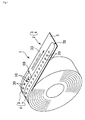
- Fig. 1 is a perspective view of the continuous body of wristbands 1 rolled in a rolled state
- Fig. 2 is a plan view of the continuous body of wristbands 1 flattened in a belt-like state.
- the continuous body of wristbands 1 is able to show identification information on a surface of a belt-like band base 2, and provided with a plurality of wristbands in series each of which may be wrapped around a portion to be wrapped such as a wrist or an ankle.
- the band base 2 includes a plurality of the band supports 3 and a plurality of the wristbands 4 provided respectively within the band supports 3.
- Materials of the band base 2 themselves are optionally selected from those suitable respectively for a back surface that is brought into contact with a human body and a front surface for showing the identification information.
- a material that is soft and highly breathable is desirable for the back surface, and a material that is printable is desirable for the front surface, and it is possible to employ a configuration in which required base materials are stacked depending on their respective functions.
- Each of the band support 3 contains a single leaf of the wristbands 4, and an area to be discarded without being used (a frame, so to speak) after the wristband 4 is removed from the band base 2.
- the band supports 3 are connected with each other by a separable connecting line 5 such as perforation provided therebetween.
- the mother wristband 7 is larger than the child wristband 8, and the child wristband 8 is smaller than the mother wristband 7. Specifically, the mother wristband 7 is longer and wider than the child wristband 8, so that the mother wristband 7 and the child wristband 8 respectively accommodate sizes of the wrists or ankles (portion to be wrapped) of mother and child.
- the outer borderline 6 and the inner borderline 9 include cutting lines that are formed as half-cuts by cutting substantially half from the back surface of the band base 2 in a through-thickness direction of the band base 2 to allow separation of the wristband 4 from the band support 3 as well as separation of the mother wristband 7 from the child wristband 8 of the wristband 4.
- the inner borderline 9 there are provided a required number of fragile partially-connecting sections 10 (two, in the example shown in the figure) having the same resistance as the perforation or the like of the connecting line 5, and this makes separation along the inner borderline 9 more difficult than separation along the outer borderline 6. In this manner, the separation resistance along the inner borderline 9 is made greater than the separation resistance along the outer borderline 6.
- the continuous body of wristbands 1 may be loaded on a printer of any type and allows printing on the front surface of the band base 2 (the wristband 4).
- Fig. 3 is a schematic side view of a thermal-transfer printer 11 as one example of the above printer, and the thermal-transfer printer 11 includes a feeder 12 for the continuous body of wristbands 1, a position detecting unit 13, and a printing unit 14.
- the feeder 12 is able to hold the continuous body of wristbands 1 in a rolled state, and feed the continuous body of wristbands 1 flattened in a belt-like state toward the position detecting unit 13 and the printing unit 14.
- the position detecting unit 13 includes a position detecting sensor 15 of any type.
- the position detecting unit 13 detects a position detection mark 16 provided on a back surface of the band support 3 of the continuous body of wristbands 1, and detects a relative position of the continuous body of wristbands 1 (the wristband 4) with respect to the printing unit 14.
- the position detection mark 16 is desirably provided for an area other than a back surface of the wristband 4 so that any ink may not be attached to skins of mother and child.
- a position-detection through hole may be provided at any portion of the band support 3, or at a different portion of lines of attachment holes 27 and 28 and adjustment holes 29 and 30 that will be later described ( Fig. 2 ) in the wristband 4, to be used for the detection of the relative position.
- the printing unit 14 includes a thermal head 17, a platen roller 18, and a feed shaft 20 and a winding shaft 21 for a thermal transfer ink ribbon 19.
- the printing unit 14 transfers the continuous body of wristbands 1 as the platen roller 18 is driven to rotate, and prints identification information relating to mother and child using the thermal head 17.
- Fig. 4 is a plan view of the band base 2 in a state in which the bar code 24 and the identification information 25 that is required are printed and shown visibly on the mother wristband 7 and the child wristband 8.
- the wristband 4 is configured separable from the band support 3 along the outer borderline 6 having the half-cut
- the wristband 8 is configured separable from the mother wristband 7 along the inner borderline 9 similarly having a half-cut. More specifically, while linear sections of the outer borderline 6 and the inner borderline 9 along the length of the wristband 4 are provided as half-cuts, both ends of the wristband 4 as separation ends are configured semicircular arc edges, one of the arc edges of the wristband 4 on an upstream side from the band support 3 in a separation direction is formed as a full-cut by cutting through the through-thickness direction of the band base 2. Specifically, as illustrated by the partially enlarged section shown in Fig.
- the mother wristband 7 and the child wristband 8 include arc edges (separation-starting arc edges 7A and 8A and separation-ending arc edges 7B and 8B) as the separation ends configured in a semicircular shape, the separation-starting arc edges 7A and 8A of the mother wristband 7 and the child wristband 8 are positioned side by side to each other, and the separation-starting arc edges 7A and 8A and the separation-ending arc edge 8B of the child wristband 8 are provided as full-cuts by cutting through the through-thickness direction of the band base 2.
- the ends of the outer borderline 6 on an upstream side in a printing direction (transfer direction) of the wristband 4 are provided as the full-cuts by cutting through the through-thickness direction of the band base 2, and therefore these arc edges (the separation-starting arc edges 7A and 8A) may not turn outward when the continuous body of wristbands 1 is loaded on the thermal-transfer printer 11 and printed while transfer, and may be used when stating separation of the wristband 4 from the band support 3.
- an arrow for separation 26, and an instruction such as "separate from this side" (not depicted) if necessary may be previously printed and shown at the separation-starting arc edges 7A and 8A.
- the separation-ending arc edge 7B of the mother wristband 7 is formed as a half-cut, as being positioned on a maximum downstream side in the printing direction (transfer direction), and thus it is possible to prevent the wristband from turning outward when the continuous body of wristbands 1 is loaded on the thermal-transfer printer 11 and printed while transfer.
- the separation-ending arc edge 8B of the child wristband 8 is a full-cut, as the separation-ending arc edge 8B is positioned more upstream side than the separation-ending arc edge 7B of the mother wristband 7 in the printing direction (transfer direction), it is less probable that the separation-ending arc edge 8B turns upward on the thermal-transfer printer 11,and the separation-ending arc edge 8B may not pose any problem in the separating operation when the child wristband 8 is separated together with the mother wristband 7 from the band support 3.
- attachment holes 27 and 28 of an optional number and the adjustment holes 29 and 30 of an optional number are provided on both end sides of the mother print area 22 of the mother wristband 7 and the child print area 23 of the child wristband 8, and the mother wristband 7 and the child wristband 8 may be clipped to form a ring by a mother attachment clip 31 and a child attachment clip 32 ( Fig. 5(3) ), respectively.
- a printing direction arrow 33 indicating the printing direction (transfer direction) by the thermal-transfer printer 11 is previously printed in a blank space of the band support 3.
- FIG. 5 is illustration of the operation of wrapping the wristband 4 of the continuous body of wristbands 1 around mother and child, in which Fig. 5(1) is a plan view of the wristband 4 separated from the band support 3, Fig. 5(2) is a perspective view of the wristband 4 wrapped around the mother's wrist W1, and Fig. 5(3) is a perspective view of the mother wristband 7 of the wristband 4 wrapped around the mother's wrist W1, and the child wristband 8 of the wristband 4 wrapped around the child's wrist W2.
- a piece having the band support 3 and the wristband 4 is obtained by printing the bar code 24, the identification information 25, and the like in the mother print area 22 and the child print area 23 of the wristband 4 using the thermal-transfer printer 11 shown in Fig. 3 , and then by separating along the connecting line 5 such as perforation.
- the separation-ending arc edge 7B of the wristband 4 on the upstream side in the printing direction (transfer direction) is a half-cut
- the separation-starting arc edge 7A and the separation-starting arc edge 8A on the downstream side in the printing direction is a full-cut
- the wristband 4 may not be separated from the band support 3 during printing.
- the separation-ending arc edge 8B of the child wristband 8 is a full-cut, it does not give a large influence as a proportion of this portion is small.
- the wristband 4 as a whole (the mother wristband 7 and the child wristband 8) is separated from the band support 3.
- the separation-starting arc edge 7A of the mother wristband 7 and the separation-starting arc edge 8A of the child wristband 8 are full-cuts, it is possible to easily complete the separation by start separating from this portion.
- the separation-ending arc edge 8B of the child wristband 8 is a full-cut, it is possible to reliably separate the separation-ending arc edge 8B from the band support 3 even though the arc portion of the separation-ending arc edge 8B is against the separation direction of the wristband 4 from the band support 3.
- a portion of the child wristband 8 is separated from the mother wristband 7 of the wristband 4 around the mother's wrist W1 in such a manner that the half-cuts and the fragile partially-connecting sections 10 are torn along the inner borderline 9, and then the child wristband 8 is wrapped around the baby's wrist W2 and fixed by the attachment clip 32 at the attachment hole 28 and adjustment hole 30 of the child wristband 8 fitting together.
- the inner borderline 9 and the outer borderline 6 have two different degrees of separation resistance due to the fragile partially-connecting sections 10 provided along the inner borderline 9, it is possible to prevent possible occurrence of separation of the child wristband 8 from the mother wristband 7 even when the wristband is worn around the mother's wrist W1, and to facilitate the operation of separating the child wristband 8 from the mother wristband 7 and wrapping the child wristband 8 around the baby.
- the configuration according to the present invention in which the separation resistance along the inner borderline 9 is greater than the separation resistance along the outer borderline 6 may be achieved by providing two different degrees of separation resistance, or three different degrees of separation resistance as need, by optionally combining the full-cuts, the half-cuts, and the fragile partially-connecting sections 10 described above.
- the outer borderline 6 is constituted by the full-cuts and the half-cuts and the inner borderline 9 is constituted by the half-cuts and the fragile partially-connecting sections 10 as in the case of the continuous body of wristbands 1 and the wristband 4 according to the first embodiment described above, or in which the outer borderline 6 is constituted by the half-cuts and the inner borderline 9 is constituted by the half-cuts and the fragile partially-connecting sections 10.
- both the outer borderline 6 and the inner borderline 9 are constituted by the half-cuts, but the depth of the half-cuts maybe configured such that the half-cuts along the outer borderline 6 are deeper, and the half-cuts along the inner borderline 9 are shallower. It should be appreciated that the fragile partially-connecting sections 10 may also be provided along the inner borderline 9 in this case.
- the band support 3 may be provided with more than one piece of the child wristbands 8 in addition to the single mother wristband 7. With this, it is possible to accommodate a case in which there are two or more babies are delivered.
- the child wristbands 8 are attached to both a wrist and an ankle of a baby, even if one of the child wristbands 8 is removed from the wrist or the ankle of the baby, it is possible to identify the baby by the remaining one of the child wristbands 8.
- Fig. 6 is a plan view of a continuous body of wristbands 40 according to a second embodiment of the present invention, and the continuous body of wristbands 40 includes the band base 2 each having the band support 3 and a wristband 41.
- the wristband 41 integrally includes a mother wristband 42, and a pair having a first child wristband 43 and a second child wristband 44.
- the wristband 41 is separated from the band support 3 along an outer borderline 45, and the first child wristband 43 and the second child wristband 44 are separated from the mother wristband 42 respectively along a first inner borderline 46 and a second inner borderline 47.
- linear sections of the outer borderline 45, the first inner borderline 46, and the second inner borderline 47 are provided as half-cuts.
- an separation-starting arc edge 42A of the mother wristband 42 on the upstream side in the printing direction (transfer direction) and the separation-starting arc edge 43A of the first child wristband 43 and the separation-starting arc edge 44A of the second child wristband 44 on the upstream side in the printing direction (transfer direction) are provided as full-cuts.
- an separation-ending arc edge 42B of the mother wristband 42 on the downstream side in the printing direction (transfer direction), and an separation-ending arc edge 43B of the first child wristband 43 and an separation-ending arc edge 44B of the second child wristband 44 on the downstream in the printing direction (transfer direction) are provided as half-cuts.
- the mother wristband 42 includes a mother print area 48
- the first child wristband 43 includes a first child print area 49
- the second child wristband 44 includes a second child print area 50.
- the width of the child print areas 49 and 50 of the first child wristband 43 and the second child wristband 44 is secured by causing slight curvature in the middle of the second inner borderline 47.
- providing an optional number of the fragile partially-connecting sections 10 for both ends of the first inner borderline 46 and the second inner borderline 47 makes a separation resistance between the mother wristband 42, and the first child wristband 43 and the second child wristband 44 be greater than the separation resistance when the wristband 41 as a whole is separated from the band support 3.
- Fig. 7 is a plan view of the band base 2 in a state in which the bar code 24 and the identification information 25 that is required are printed and shown visibly on the mother wristband 42, the first child wristband 43, and the second child wristband 44.
- the bar code 24 and the identification information may also be printed as variable information by loading the continuous body of wristbands on the thermal-transfer printer 11 ( Fig. 3 ).
- the continuous body of wristbands 40 and the wristband 41 it is possible to print the required identification information 25 on the mother wristband 42, the first child wristband 43, and the second child wristband 44 that are necessary for identification of mother and baby or babies, in particular in the case in which twins are delivered or in which the wristbands are wrapped around both wrist and ankle of a baby.
- first inner borderline 46 and the second inner borderline 47 that are half-cut are provided with the fragile partially-connecting sections 10, it is possible to prevent an possible occurrence of unintentional separation of the first child wristband 43 and the second child wristband 44 from the mother wristband 42. After the delivery, the first child wristband 43 and the second child wristband 44 are separated from the mother wristband 42 to be wrapped around a wrist and an ankle of the baby.
Landscapes
- Physics & Mathematics (AREA)
- General Physics & Mathematics (AREA)
- Engineering & Computer Science (AREA)
- Theoretical Computer Science (AREA)
- Professional, Industrial, Or Sporting Protective Garments (AREA)
- Accommodation For Nursing Or Treatment Tables (AREA)
Abstract
Description
- The present invention relates to a continuous body of wristbands and a wristband, and in particular to a continuous body of wristbands and a wristband for identifying a patient in a medical field and the like by attaching the wristband by wrapping the wristband around a patient's wrist or ankle.
- Conventionally, a wristband, especially that for medical-use, on which name, birth date, sex, and other necessary information (identification information) of a hospitalized patient are handwritten or printed is wrapped around the patient's wrist or ankle (portion to be wrapped) so as to allow identification of the hospitalized patient, and thus enables verification of the hospitalized patient in examination or treatment.
- However, conventionally, wristbands for a mother and an infant or child used in the field of obstetrics and gynecology or emergency first aid for accidents are often separately prepared and attached. Specifically, a wristband for mother is issued and attached to an expectant mother upon admission of the mother into a hospital, and a wristband for child is issued and attached to a baby upon delivery of the baby. Such a configuration of the wristbands or an issuing process of the wristbands involves a problem that mother-infant relation may be misidentified, possibly resulting in mix-ups of babies.
- It should be noted that, as described in
PTL 1, there is contrived a mother-infant-in-one wristband in which a mother wristband and a child wristband are integrally formed and together applied to a mother, and then upon delivery of a baby, the child wristband is separated from the mother wristband to be attached to the baby. However, as a separation resistance for separating a wristband from a band main body along a cutting line such as perforation or the like is even, there are such problems that a child wristband is separated from a mother wristband when separating a mother-infant-in-one wristband, and that a child wristband is unintentionally separated from a mother-infant-in-one wristband attached to a mother, and possibly lost. - PTL 1: Japanese Unexamined Patent Application Publication No.
2003-157010 - The present invention has been made in view of the above problems, and an object of the present invention is to provide a continuous body of wristbands and a wristband that may be integrally used for mother and child.
- Another object of the present invention is to provide a continuous body of wristbands and a wristband eliminating any problem that may occur when the wristband is separated or when a child wristband is separated from a mother wristband.
- Yet another object of the present invention is to provide a continuous body of wristbands and a wristband capable of preventing unintentional separation of a child wristband when the wristband is separated or when a mother wristband and the child wristband are attached to a mother.
- Specifically, the present invention focuses attention on increasing a separation resistance between a mother wristband and a child wristband. A first aspect of the invention provides a continuous body of wristbands in a belt-like state allowing identification information to be shown on a belt-like band base, and having a plurality of wristbands wrappable around a portion to be wrapped such as a wrist or an ankle in series, wherein the band base material comprises: band supports; and the wristbands each provided within an area inside each of the band supports with an outer borderline disposed between the each wristband and the each band support, and the wristband includes a mother wristband and a child wristband integrally formed side by side with an inner borderline disposed therebetween, and is configured such that a separation resistance along the inner borderline is greater than a separation resistance along the outer borderline.
- A second aspect of the invention provides a wristband comprsing a band base material, allowing identification information to be shown on a front surface of the band base, and wrappable around a portion to be wrapped such as a wrist or an ankle, wherein the band base material comprises: a band support; and the wristband provided within an area inside the band support with an outer borderline disposed between the wristband and the band support, and the wristband includes a mother wristband and a child wristband integrally formed side by side with an inner borderline disposed therebetween, and is configured such that a separation resistance along the inner borderline is greater than a separation resistance along the outer borderline.
- The outer borderline and the inner borderline may include cutting lines each formed as a half-cut by cutting substantially half in a through-thickness direction of the band base.
- The inner borderline may be provided with a fragile partially-connecting section.
- The band supports may be connected with each other with a separable connecting line disposed therebetween.
- The continuous body of wristbands may be loadable on a printer to allow printing on a front surface of the band base, and ends of the outer borderline on an upstream side in a printing direction may be each formed as a full-cut by cutting through the through-thickness direction of the band base.
- Both ends of the wristband may be configured as arc edges, and one of the arc edges of the wristband on an upstream side in a separation direction from the band support may be formed as a full-cut by cutting through the through-thickness direction of the band base.
- The mother wristband may be made larger, and the child wristband may be made smaller.
- An end of the child wristband on a downstream side in the separation direction from the band support may be formed as a full-cut by cutting through the through-thickness direction of the band base.
- The mother wristband and the child wristband respectively may include the arc edges as separation ends made in a semicircular shape, the arc edges for starting separation respectively of the mother wristband and the child wristband may be positioned side by side to each other, and the arc edges for starting separation and the arc edge for ending separation of the child wristband may be each formed as a full-cut by cutting through the through-thickness direction of the band base.
- The mother wristband and the child wristband may each include a print area on which a bar code relating to the identification information is allowed to be printed across the inner borderline.
- The mother wristband and the child wristband may be decorated in an identical design.
- According to a continuous body of wristbands and a wristband of the present invention, each wristband including the mother wristband and the child wristband integrally formed side by side with the inner borderline disposed therebetween is provided within the area inside each band support with the outer borderline disposed between the wristband and the band support. The wristband is configured such that the separation resistance along the inner borderline is greater than the separation resistance along the outer borderline. Thus, it is possible to prevent the child wristband from being unintentionally separated when the wristband is separated from the band support, prevent the child wristband from being unintentionally separated from the wristband attached to mother, ensure identification of mother and child by the wristband, assure management information relating to patients, and prevent accidents such as mix-ups of babies from occurring.
- In particular, according to the continuous body of wristbands of the first aspect of the invention, as the plurality of wristbands are provided in a belt-like state, the continuous body of wristbands may be loaded on a printer of any type, identification information relating to mother and child may be printed and shown as needed, and a wristband (a mother wristband and a child wristband) may be separated from a single band base and attached to mother in use.
- In particular, according to the wristband of the second aspect of the invention, upon separation of the wristband from the band support, the wristband may be integrally separated without unintentionally separating the child wristband from the mother wristband. In addition, when the mother wristband is attached to mother integrally with the child wristband, it is possible to prevent the child wristband from being unintentionally separated from the mother wristband.
-
-
Fig. 1 is a perspective view of a continuous body ofwristbands 1 rolled in a rolled state according to a first embodiment of the present invention. -
Fig. 2 is a plan view of the continuous body ofwristbands 1 flattened in a belt-like state. -
Fig. 3 is a schematic side view of a thermal-transfer printer 11. -
Fig. 4 is a plan view of aband base 2 in a state in which abar code 24 andidentification information 25 that is required are printed and shown visibly on amother wristband 7 and achild wristband 8. -
Fig. 5 is illustration of an operation of wrapping awristband 4 of the continuous body ofwristbands 1 around mother and child, in whichFig. 5(1) is a plan view of thewristband 4 separated from aband support 3,Fig. 5(2) is a perspective view of thewristband 4 wrapped around a mother' s wrist W1, andFig. 5(3) is a perspective view of themother wristband 7 of thewristband 4 wrapped around the mother's wrist W1, and thechild wristband 8 of thewristband 4 wrapped around a child's wrist W2. -
Fig. 6 is a plan view of a continuous body ofwristbands 40 according to a second embodiment of the present invention. -
Fig. 7 is a plan view of theband base 2 in a state in which thebar code 24 and theidentification information 25 that is required are printed and shown visibly on amother wristband 42, afirst child wristband 43, and asecond child wristband 44. - According to the present invention, a resistance for separating a child wristband from a mother wristband is greater than a resistance for separating a wristband as a whole including the mother wristband and the child wristband from a band support. Thus, it is possible to achieve a continuous body of wristbands and a wristband capable of facilitating separation of a mother-infant-in-one wristband, preventing the child wristband from being unintentionally separated from the mother wristband when the mother wristband and the child wristband are separated together from the band support or attached to a mother, and correctly securing a function of identifying mother and child so as to prevent accidents such as mix-ups of babies from occurring.
- Hereinafter, a continuous body of
wristbands 1 and awristband 4 according to a first embodiment of the present invention will be described with reference toFig. 1 to Fig. 5 .Fig. 1 is a perspective view of the continuous body ofwristbands 1 rolled in a rolled state, andFig. 2 is a plan view of the continuous body ofwristbands 1 flattened in a belt-like state. The continuous body ofwristbands 1 is able to show identification information on a surface of a belt-like band base 2, and provided with a plurality of wristbands in series each of which may be wrapped around a portion to be wrapped such as a wrist or an ankle. - The
band base 2 includes a plurality of the band supports 3 and a plurality of thewristbands 4 provided respectively within the band supports 3. Materials of theband base 2 themselves are optionally selected from those suitable respectively for a back surface that is brought into contact with a human body and a front surface for showing the identification information. A material that is soft and highly breathable is desirable for the back surface, and a material that is printable is desirable for the front surface, and it is possible to employ a configuration in which required base materials are stacked depending on their respective functions. - Each of the
band support 3 contains a single leaf of thewristbands 4, and an area to be discarded without being used (a frame, so to speak) after thewristband 4 is removed from theband base 2. The band supports 3 are connected with each other by a separable connectingline 5 such as perforation provided therebetween. - The
wristband 4 is provided within an area inside theband support 3 with an outer borderline 6 therebetween, and includes amother wristband 7 and achild wristband 8 integrally formed side by side with an inner borderline 9 therebetween. The outer borderline 6 constitutes an outer edge or an outline of thewristband 4 and contains themother wristband 7 and thechild wristband 8 therein. Along the outer borderline 6, thewristband 4 is integrally separated from theband support 3. Theinner borderline 9 is linearly positioned along a border portion where the mother wristband 7 and thechild wristband 8 are adjacent to each other. Along the inner borderline 9, themother wristband 7 and thechild wristband 8 are separated. - The
mother wristband 7 is larger than thechild wristband 8, and thechild wristband 8 is smaller than themother wristband 7. Specifically, the mother wristband 7 is longer and wider than thechild wristband 8, so that the mother wristband 7 and thechild wristband 8 respectively accommodate sizes of the wrists or ankles (portion to be wrapped) of mother and child. - As illustrated by a partially enlarged section shown in
Fig. 2 , theouter borderline 6 and theinner borderline 9 include cutting lines that are formed as half-cuts by cutting substantially half from the back surface of theband base 2 in a through-thickness direction of theband base 2 to allow separation of thewristband 4 from theband support 3 as well as separation of themother wristband 7 from thechild wristband 8 of thewristband 4. However, near each end of thechild wristband 8 along theinner borderline 9, there are provided a required number of fragile partially-connecting sections 10 (two, in the example shown in the figure) having the same resistance as the perforation or the like of the connectingline 5, and this makes separation along theinner borderline 9 more difficult than separation along theouter borderline 6. In this manner, the separation resistance along theinner borderline 9 is made greater than the separation resistance along theouter borderline 6. - The continuous body of
wristbands 1 may be loaded on a printer of any type and allows printing on the front surface of the band base 2 (the wristband 4).Fig. 3 is a schematic side view of a thermal-transfer printer 11 as one example of the above printer, and the thermal-transfer printer 11 includes afeeder 12 for the continuous body ofwristbands 1, aposition detecting unit 13, and aprinting unit 14. - The
feeder 12 is able to hold the continuous body ofwristbands 1 in a rolled state, and feed the continuous body ofwristbands 1 flattened in a belt-like state toward theposition detecting unit 13 and theprinting unit 14. - The
position detecting unit 13 includes aposition detecting sensor 15 of any type. Theposition detecting unit 13 detects aposition detection mark 16 provided on a back surface of theband support 3 of the continuous body ofwristbands 1, and detects a relative position of the continuous body of wristbands 1 (the wristband 4) with respect to theprinting unit 14. Here, theposition detection mark 16 is desirably provided for an area other than a back surface of thewristband 4 so that any ink may not be attached to skins of mother and child. Further, in place of theposition detection mark 16, a position-detection through hole (not depicted) may be provided at any portion of theband support 3, or at a different portion of lines of attachment holes 27 and 28 and adjustment holes 29 and 30 that will be later described (Fig. 2 ) in thewristband 4, to be used for the detection of the relative position. - The
printing unit 14 includes athermal head 17, aplaten roller 18, and afeed shaft 20 and a windingshaft 21 for a thermaltransfer ink ribbon 19. Theprinting unit 14 transfers the continuous body ofwristbands 1 as theplaten roller 18 is driven to rotate, and prints identification information relating to mother and child using thethermal head 17. - Using the thermal-
transfer printer 11 thus configured, upon admission of an expectant mother into a hospital, required identification information are printed as pieces of variable information respectively on amother print area 22 of themother wristband 7 and achild print area 23 of thechild wristband 8. However, thebar code 24 relating to the identification information may be printed across theinner borderline 9 over themother print area 22 and thechild print area 23. With this, it is possible to reliably print and show the same identification information for mother and child at one time, and to manage mother and child by a common code even after thechild wristband 8 is separated from themother wristband 7.Fig. 4 is a plan view of theband base 2 in a state in which thebar code 24 and theidentification information 25 that is required are printed and shown visibly on themother wristband 7 and thechild wristband 8. - Referring back to
Fig. 2 , as described previously, thewristband 4 is configured separable from theband support 3 along theouter borderline 6 having the half-cut, and thewristband 8 is configured separable from themother wristband 7 along theinner borderline 9 similarly having a half-cut. More specifically, while linear sections of theouter borderline 6 and theinner borderline 9 along the length of thewristband 4 are provided as half-cuts, both ends of thewristband 4 as separation ends are configured semicircular arc edges, one of the arc edges of thewristband 4 on an upstream side from theband support 3 in a separation direction is formed as a full-cut by cutting through the through-thickness direction of theband base 2. Specifically, as illustrated by the partially enlarged section shown inFig. 2 , themother wristband 7 and thechild wristband 8 include arc edges (separation-starting arc edges 7A and 8A and separation-endingarc edges mother wristband 7 and thechild wristband 8 are positioned side by side to each other, and the separation-starting arc edges 7A and 8A and the separation-endingarc edge 8B of thechild wristband 8 are provided as full-cuts by cutting through the through-thickness direction of theband base 2. - In other words, the ends of the
outer borderline 6 on an upstream side in a printing direction (transfer direction) of the wristband 4 (the separation-starting arc edges 7A and 8A) are provided as the full-cuts by cutting through the through-thickness direction of theband base 2, and therefore these arc edges (the separation-starting arc edges 7A and 8A) may not turn outward when the continuous body ofwristbands 1 is loaded on the thermal-transfer printer 11 and printed while transfer, and may be used when stating separation of thewristband 4 from theband support 3. Here, an arrow forseparation 26, and an instruction such as "separate from this side" (not depicted) if necessary, may be previously printed and shown at the separation-starting arc edges 7A and 8A. However, the separation-endingarc edge 7B of themother wristband 7 is formed as a half-cut, as being positioned on a maximum downstream side in the printing direction (transfer direction), and thus it is possible to prevent the wristband from turning outward when the continuous body ofwristbands 1 is loaded on the thermal-transfer printer 11 and printed while transfer. Further, even if the separation-endingarc edge 8B of thechild wristband 8 is a full-cut, as the separation-endingarc edge 8B is positioned more upstream side than the separation-endingarc edge 7B of themother wristband 7 in the printing direction (transfer direction), it is less probable that the separation-endingarc edge 8B turns upward on the thermal-transfer printer 11,and the separation-endingarc edge 8B may not pose any problem in the separating operation when thechild wristband 8 is separated together with themother wristband 7 from theband support 3. Here, it is also possible to provide a configuration such that turning outward during printing while transfer with in the thermal-transfer printer 11 is reliably prevented by making a tipend arc portion 8C of the separation-endingarc edge 8B of the child wristband 8 a half-cut, and that it is possible to ensure the separating operation when separating thewristband 4 from theband support 3 by making an arc portion from the tipend arc portion 8C to theinner borderline 9 and an arc-portion-facinglinear portion 7C of theouter borderline 6 of themother wristband 7 facing the arc portion full-cuts even along theouter borderline 6. - It should be noted that the attachment holes 27 and 28 of an optional number and the adjustment holes 29 and 30 of an optional number are provided on both end sides of the
mother print area 22 of themother wristband 7 and thechild print area 23 of thechild wristband 8, and themother wristband 7 and thechild wristband 8 may be clipped to form a ring by amother attachment clip 31 and a child attachment clip 32 (Fig. 5(3) ), respectively. - Further, a
printing direction arrow 33 indicating the printing direction (transfer direction) by the thermal-transfer printer 11 is previously printed in a blank space of theband support 3. - Moreover, by decorating the
mother wristband 7 and thechild wristband 8 optionally in the same design (not depicted), their totality may be visually confirmed more reliably. However, by employing the same design while selecting a pink background for themother wristband 7 and a background of a different color such as yellow for thechild wristband 8, it is possible to make themother wristband 7 and thechild wristband 8 identifiable while the design still provides a sense of unity. - An operation of wrapping the
wristband 4 of the continuous body ofwristbands 1 thus configured around mother and child will be described with reference toFig. 5. Fig. 5 is illustration of the operation of wrapping thewristband 4 of the continuous body ofwristbands 1 around mother and child, in whichFig. 5(1) is a plan view of thewristband 4 separated from theband support 3,Fig. 5(2) is a perspective view of thewristband 4 wrapped around the mother's wrist W1, andFig. 5(3) is a perspective view of themother wristband 7 of thewristband 4 wrapped around the mother's wrist W1, and thechild wristband 8 of thewristband 4 wrapped around the child's wrist W2. - As illustrated in
Fig. 4 , a piece having theband support 3 and thewristband 4 is obtained by printing thebar code 24, theidentification information 25, and the like in themother print area 22 and thechild print area 23 of thewristband 4 using the thermal-transfer printer 11 shown inFig. 3 , and then by separating along the connectingline 5 such as perforation. At this time of printing, as the separation-endingarc edge 7B of thewristband 4 on the upstream side in the printing direction (transfer direction) is a half-cut, and the separation-startingarc edge 7A and the separation-startingarc edge 8A on the downstream side in the printing direction is a full-cut, thewristband 4 may not be separated from theband support 3 during printing. Here, while the separation-endingarc edge 8B of thechild wristband 8 is a full-cut, it does not give a large influence as a proportion of this portion is small. - As illustrated in
Fig. 5(1) , thewristband 4 as a whole (themother wristband 7 and the child wristband 8) is separated from theband support 3. At this time of separation, as the separation-startingarc edge 7A of themother wristband 7 and the separation-startingarc edge 8A of thechild wristband 8 are full-cuts, it is possible to easily complete the separation by start separating from this portion. It should be noted that as the separation-endingarc edge 8B of thechild wristband 8 is a full-cut, it is possible to reliably separate the separation-endingarc edge 8B from theband support 3 even though the arc portion of the separation-endingarc edge 8B is against the separation direction of thewristband 4 from theband support 3. - Next, as illustrated in
Fig. 5(2) , thewristband 4, in a state in which themother wristband 7 and thechild wristband 8 are connected in one piece, is wrapped around the mother's wrist W1 and fixed by anattachment clip 31 at theattachment hole 27 and theadjustment hole 29 of themother wristband 7 fitting together. - As illustrated in
Fig. 5(3) , when a baby is born, a portion of thechild wristband 8 is separated from themother wristband 7 of thewristband 4 around the mother's wrist W1 in such a manner that the half-cuts and the fragile partially-connectingsections 10 are torn along theinner borderline 9, and then thechild wristband 8 is wrapped around the baby's wrist W2 and fixed by theattachment clip 32 at theattachment hole 28 andadjustment hole 30 of thechild wristband 8 fitting together. - In this manner, it is possible to easily complete printing to the
wristband 4, separation of thewristband 4 from theband support 3, and wrapping around the mother's wrist W1 without any problem. Further, as theinner borderline 9 and theouter borderline 6 have two different degrees of separation resistance due to the fragile partially-connectingsections 10 provided along theinner borderline 9, it is possible to prevent possible occurrence of separation of thechild wristband 8 from themother wristband 7 even when the wristband is worn around the mother's wrist W1, and to facilitate the operation of separating thechild wristband 8 from themother wristband 7 and wrapping thechild wristband 8 around the baby. - It should be noted that the configuration according to the present invention in which the separation resistance along the
inner borderline 9 is greater than the separation resistance along theouter borderline 6 may be achieved by providing two different degrees of separation resistance, or three different degrees of separation resistance as need, by optionally combining the full-cuts, the half-cuts, and the fragile partially-connectingsections 10 described above. For example, it is possible to employ a combination in which theouter borderline 6 is constituted by the full-cuts and the half-cuts and theinner borderline 9 is constituted by the half-cuts and the fragile partially-connectingsections 10 as in the case of the continuous body ofwristbands 1 and thewristband 4 according to the first embodiment described above, or in which theouter borderline 6 is constituted by the half-cuts and theinner borderline 9 is constituted by the half-cuts and the fragile partially-connectingsections 10. Alternatively, it is possible to employ a configuration in which both theouter borderline 6 and theinner borderline 9 are constituted by the half-cuts, but the depth of the half-cuts maybe configured such that the half-cuts along theouter borderline 6 are deeper, and the half-cuts along theinner borderline 9 are shallower. It should be appreciated that the fragile partially-connectingsections 10 may also be provided along theinner borderline 9 in this case. - Further, according to the present invention, the
band support 3 may be provided with more than one piece of thechild wristbands 8 in addition to thesingle mother wristband 7. With this, it is possible to accommodate a case in which there are two or more babies are delivered. In addition, when thechild wristbands 8 are attached to both a wrist and an ankle of a baby, even if one of thechild wristbands 8 is removed from the wrist or the ankle of the baby, it is possible to identify the baby by the remaining one of thechild wristbands 8. - Specifically,
Fig. 6 is a plan view of a continuous body ofwristbands 40 according to a second embodiment of the present invention, and the continuous body ofwristbands 40 includes theband base 2 each having theband support 3 and awristband 41. - The
wristband 41 integrally includes amother wristband 42, and a pair having afirst child wristband 43 and asecond child wristband 44. Thewristband 41 is separated from theband support 3 along anouter borderline 45, and thefirst child wristband 43 and thesecond child wristband 44 are separated from themother wristband 42 respectively along a firstinner borderline 46 and a secondinner borderline 47. - Specifically, linear sections of the
outer borderline 45, the firstinner borderline 46, and the secondinner borderline 47 are provided as half-cuts. Further, an separation-startingarc edge 42A of themother wristband 42 on the upstream side in the printing direction (transfer direction), and the separation-starting arc edge 43A of thefirst child wristband 43 and the separation-startingarc edge 44A of thesecond child wristband 44 on the upstream side in the printing direction (transfer direction) are provided as full-cuts. In addition, an separation-endingarc edge 42B of themother wristband 42 on the downstream side in the printing direction (transfer direction), and an separation-endingarc edge 43B of thefirst child wristband 43 and an separation-endingarc edge 44B of thesecond child wristband 44 on the downstream in the printing direction (transfer direction) are provided as half-cuts. - However, prevention of the wristband from turning outward when printing while transfer in the thermal-
transfer printer 11 is ensured by providing a tipend arc portion 42C of the separation-endingarc edge 42B of themother wristband 42, a tipend arc portion 43C of the separation-endingarc edge 43B of thefirst child wristband 43, and a tipend arc portion 44C of the separation-endingarc edge 44B of thesecond child wristband 44 as half-cuts. Further, by providing arc portions from the tipend arc portions inner borderline 46 and the secondinner borderline 47 as full-cuts even along theouter borderline 45, reliability in the operation of separating thewristband 41 from theband support 3 is ensured. Moreover, by providing an arc-portion-facing linear portion 42D of themother wristband 42 along theouter borderline 45 that faces the separation-starting arc edge 43A of thefirst child wristband 43 on the upstream side in the printing direction (transfer direction) as full-cuts even along theouter borderline 45, reliability in the operation of separating thewristband 41 fromband support 3 is ensured. - The
mother wristband 42 includes amother print area 48, thefirst child wristband 43 includes a firstchild print area 49, and thesecond child wristband 44 includes a secondchild print area 50. The width of thechild print areas first child wristband 43 and thesecond child wristband 44 is secured by causing slight curvature in the middle of the secondinner borderline 47. - Here, providing an optional number of the fragile partially-connecting
sections 10 for both ends of the firstinner borderline 46 and the secondinner borderline 47 makes a separation resistance between themother wristband 42, and thefirst child wristband 43 and thesecond child wristband 44 be greater than the separation resistance when thewristband 41 as a whole is separated from theband support 3. -
Fig. 7 is a plan view of theband base 2 in a state in which thebar code 24 and theidentification information 25 that is required are printed and shown visibly on themother wristband 42, thefirst child wristband 43, and thesecond child wristband 44. Thebar code 24 and the identification information may also be printed as variable information by loading the continuous body of wristbands on the thermal-transfer printer 11 (Fig. 3 ). - Similarly to the existing continuous body of wristbands 1 (
Fig. 1 ) and the existing wristband 4 (Fig. 2 ) of the first embodiment, according to the continuous body ofwristbands 40 and thewristband 41 thus configured, it is possible to print the requiredidentification information 25 on themother wristband 42, thefirst child wristband 43, and thesecond child wristband 44 that are necessary for identification of mother and baby or babies, in particular in the case in which twins are delivered or in which the wristbands are wrapped around both wrist and ankle of a baby. - Further, in separation of the
wristband 41 from theband support 3 in a single piece of theband base 2 separated by the connectingline 5, starting separation from the full-cut separation-startingarc edge 42A of themother wristband 42 allows themother wristband 42, thefirst child wristband 43, and thesecond child wristband 44 to be separated integrally along the half-cutouter borderline 45 easily and reliably as thewristband 41. Thewristband 41 is wrapped around the mother's wrist W1 in the same manner as the wristband 4 (Fig. 2 ). As the firstinner borderline 46 and the secondinner borderline 47 that are half-cut are provided with the fragile partially-connectingsections 10, it is possible to prevent an possible occurrence of unintentional separation of thefirst child wristband 43 and thesecond child wristband 44 from themother wristband 42. After the delivery, thefirst child wristband 43 and thesecond child wristband 44 are separated from themother wristband 42 to be wrapped around a wrist and an ankle of the baby. -
- 1: Continuous body of wristbands (First Embodiment,
Fig. 1 ) - 2: Band Base
- 3: Band Support
- 4: Wristband (First Embodiment,
Fig. 2 ) - 5: Connecting Line such as Perforation
- 6: Outer Borderline
- 7: Mother Wristband
- 7A: Separation-Starting Arc Edge of Mother Wristband 7 (Arc Edge)
- 7B: Separation-Ending Arc Edge of Mother Wristband 7 (Arc Edge)
- 7C: Arc-Portion-Facing Linear Portion of
Outer Borderline 6 ofMother Wristband 7 - 8: Child Wristband
- 8A: Separation-Starting Arc Edge of Child Wristband 8 (Arc Edge)
- 8B: Separation-Ending Arc Edge of Child Wristband 8 (Arc Edge)
- 8C: Tip End Arc Portion of Separation-
Ending Arc Edge 8B ofChild Wristband 8 - 9: Inner Borderline
- 10: Fragile Partially-Connecting Section
- 11: Thermal-Transfer Printer (
Fig. 3 ) - 12: Feeder of Continuous body of
wristbands 1 - 13: Position Detecting Unit
- 14: Printing Unit
- 15: Position Detecting Sensor
- 16: Position Detection Mark
- 17: Thermal Head
- 18: Platen Roller
- 19: Thermal Transfer Ink Ribbon
- 20: Feed Shaft
- 21: Winding Shaft
- 22: Mother Print Area (Print Area)
- 23: Child Print Area (Print Area)
- 24: Bar Code
- 25: Identification Information
- 26: Arrow for Separation
- 27: Attachment Hole
- 28: Attachment Hole
- 29: Adjustment Hole
- 30: Adjustment Hole
- 31: Mother Attachment Clip
- 32: Child Attachment Clip
- 33: Printing Direction Arrow
- 40: Continuous body of wristbands (Second Embodiment,
Fig. 6 ) - 41: Wristband (Second Embodiment,
Fig. 6 ) - 42: Mother Wristband
- 42A: Separation-Starting Arc Edge of Mother Wristband 42 (Arc Edge)
- 42B: Separation-Ending Arc Edge of Mother Wristband 42 (Arc Edge)
- 42C: Tip End Arc Portion of Separation-
Ending Arc Edge 42B ofMother Wristband 42 - 42D: Arc-Portion-Facing Linear Portion of
Outer Borderline 45 ofMother Wristband 42 - 43: First Child Wristband
- 43A: Separation-Starting Arc Edge of First Child Wristband 43 (Arc Edge)
- 43B: Separation-Ending Arc Edge of First Child Wristband 43 (Arc Edge)
- 43C: Tip End Arc Portion of Separation-
Ending Arc Edge 43B ofFirst Child Wristband 43 - 44: Second Child Wristband
- 44A: Separation-Starting Arc Edge of Second Child Wristband 44 (Arc Edge)
- 44B: Separation-Ending Arc Edge of Second Child Wristband 44 (Arc Edge)
- 44C: Tip End Arc Portion of Separation-
Ending Arc Edge 44B ofSecond Child Wristband 44 - 45: Outer Borderline
- 46: First Inner Borderline (Inner Borderline)
- 47: Second Inner Borderline (Inner Borderline)
- 48: Mother Print Area (Print Area)
- 49: First Child Print Area (Print Area)
- 50: Second Child Print Area (Print Area)
- W1: Mother's Wrist (Portion to be Wrapped)
- W2: Child's Wrist (Portion to be Wrapped)
Claims (12)
- A continuous body of wristbands in a belt-like state allowing identification information to be shown on a belt-like band base, and having a plurality of wristbands wrappable around a portion to be wrapped such as a wrist or an ankle in series, wherein
the band base material comprises:band supports; andthe wristbands each provided within an area inside each of the band supports with an outer borderline disposed between the each wristband and the each band support, andthe wristband includes a mother wristband and a child wristband integrally formed side by side with an inner borderline disposed therebetween, and is configured such that a separation resistance along the inner borderline is greater than a separation resistance along the outer borderline. - The continuous body of wristbands according to claim 1, wherein
the outer borderline and the inner borderline include cutting lines each formed as a half-cut by cutting substantially half in a through-thickness direction of the band base. - The continuous body of wristbands according to claim 1 or 2, wherein
the inner borderline is provided with a fragile partially-connecting section. - The continuous body of wristbands according to one of claims 1 to 3, wherein
the band supports are connected with each other with a separable connecting line disposed therebetween. - The continuous body of wristbands according to one of claims 1 to 4, wherein
the continuous body of wristbands is loadable on a printer to allow printing on a front surface of the band base, and
ends of the outer borderline on an upstream side in a printing direction are each formed as a full-cut by cutting through the through-thickness direction of the band base. - The continuous body of wristbands according to one of claims 1 to 5, wherein
both ends of the wristband are configured as arc edges, and one of the arc edges of the wristband on an upstream side in a separation direction from the band support is formed as a full-cut by cutting through the through-thickness direction of the band base. - The continuous body of wristbands according to one of claims 1 to 6, wherein
the mother wristband is made larger, and
the child wristband is made smaller. - The continuous body of wristbands according to claim 7, wherein
an end of the child wristband on a downstream side in the separation direction from the band support is formed as a full-cut by cutting through the through-thickness direction of the band base. - The continuous body of wristbands according to claim 7, wherein
the mother wristband and the child wristband respectively include the arc edges as separation ends made in a semicircular shape,
the arc edges for starting separation respectively of the mother wristband and the child wristband are positioned side by side to each other, and
the arc edges for starting separation and the arc edge for ending separation of the child wristband are each formed as a full-cut by cutting through the through-thickness direction of the band base. - The continuous body of wristbands according to one of claims 1 to 9, wherein
the mother wristband and the child wristband each include a print area on which a bar code relating to the identification information is allowed to be printed across the inner borderline. - The continuous body of wristbands according to one of claims 1 to 10, wherein
the mother wristband and the child wristband are decorated in an identical design. - A wristband comprising a band base material, allowing identification information to be shown on a front surface of the band base, and wrappable around a portion to be wrapped such as a wrist or an ankle, wherein
the band base material comprises:a band support; andthe wristband provided within an area inside the band support with an outer borderline disposed between the wristband and the band support, andthe wristband includes a mother wristband and a child wristband integrally formed side by side with an inner borderline disposed therebetween, and is configured such that a separation resistance along the inner borderline is greater than a separation resistance along the outer borderline.
Applications Claiming Priority (2)
| Application Number | Priority Date | Filing Date | Title |
|---|---|---|---|
| JP2011253009 | 2011-11-18 | ||
| PCT/JP2012/007007 WO2013073123A1 (en) | 2011-11-18 | 2012-11-01 | Series of wristbands, and wristband |
Publications (3)
| Publication Number | Publication Date |
|---|---|
| EP2782088A1 true EP2782088A1 (en) | 2014-09-24 |
| EP2782088A4 EP2782088A4 (en) | 2015-07-29 |
| EP2782088B1 EP2782088B1 (en) | 2020-07-15 |
Family
ID=48429224
Family Applications (1)
| Application Number | Title | Priority Date | Filing Date |
|---|---|---|---|
| EP12849199.0A Active EP2782088B1 (en) | 2011-11-18 | 2012-11-01 | Series of wristbands, and wristband |
Country Status (8)
| Country | Link |
|---|---|
| EP (1) | EP2782088B1 (en) |
| JP (1) | JP6017931B2 (en) |
| CN (1) | CN103975375B (en) |
| AU (1) | AU2012338245B2 (en) |
| IN (1) | IN2014CN02201A (en) |
| MY (1) | MY166249A (en) |
| SG (1) | SG11201402395YA (en) |
| WO (1) | WO2013073123A1 (en) |
Cited By (1)
| Publication number | Priority date | Publication date | Assignee | Title |
|---|---|---|---|---|
| US10261473B2 (en) | 2015-04-02 | 2019-04-16 | Bridger Bell | Wristband for use with wrist-worn device |
Families Citing this family (3)
| Publication number | Priority date | Publication date | Assignee | Title |
|---|---|---|---|---|
| JP2015161805A (en) * | 2014-02-27 | 2015-09-07 | ゼネラル株式会社 | label sheet |
| JP2019211651A (en) * | 2018-06-06 | 2019-12-12 | 小林クリエイト株式会社 | Wristband |
| US12093770B2 (en) * | 2021-05-13 | 2024-09-17 | Zebra Technologies Corporation | Arrangement and assembly of a set of wristbands |
Family Cites Families (13)
| Publication number | Priority date | Publication date | Assignee | Title |
|---|---|---|---|---|
| US3467246A (en) * | 1967-04-07 | 1969-09-16 | Precision Dynamics Corp | Multiple identification band assembly and method of making the same |
| GB1227497A (en) * | 1969-07-04 | 1971-04-07 | ||
| US3965589A (en) * | 1975-02-12 | 1976-06-29 | Bio-Logics Products, Inc. | Identification means |
| US6510634B1 (en) * | 1997-10-14 | 2003-01-28 | Laser Band, Llc | Multiple computer generated multi-web moisture proof identification bracelets on a single form with window |
| JPH11219115A (en) * | 1998-02-04 | 1999-08-10 | Konica Corp | Pricing label and photo bag |
| DE69926516D1 (en) * | 1999-12-22 | 2005-09-08 | Identificacion Y Custodia Neon | Coded means and system for babies care |
| JP2002363808A (en) * | 2001-05-31 | 2002-12-18 | Sato Corp | Wristband |
| JP2003157010A (en) * | 2001-11-21 | 2003-05-30 | Sato Corp | Wristband continuum |
| JP2003164499A (en) * | 2001-12-03 | 2003-06-10 | Dainippon Printing Co Ltd | Report with wristband for medical management |
| US20070283607A1 (en) * | 2006-06-13 | 2007-12-13 | Printmark Industries, Inc. | Printed identification band and method of manufacturing same |
| JP4856143B2 (en) * | 2008-09-29 | 2012-01-18 | 株式会社サトー知識財産研究所 | Label with reattachment area |
| CN201757958U (en) * | 2010-05-13 | 2011-03-09 | 广州市宝比塑料制品有限公司 | Male and female identification wrist belt |
| JP2012061132A (en) * | 2010-09-16 | 2012-03-29 | Seiko Epson Corp | Printing method and printer |
-
2012
- 2012-11-01 AU AU2012338245A patent/AU2012338245B2/en active Active
- 2012-11-01 WO PCT/JP2012/007007 patent/WO2013073123A1/en not_active Ceased
- 2012-11-01 SG SG11201402395YA patent/SG11201402395YA/en unknown
- 2012-11-01 EP EP12849199.0A patent/EP2782088B1/en active Active
- 2012-11-01 MY MYPI2014000782A patent/MY166249A/en unknown
- 2012-11-01 IN IN2201CHN2014 patent/IN2014CN02201A/en unknown
- 2012-11-01 CN CN201280056710.5A patent/CN103975375B/en active Active
- 2012-11-16 JP JP2012251737A patent/JP6017931B2/en active Active
Cited By (1)
| Publication number | Priority date | Publication date | Assignee | Title |
|---|---|---|---|---|
| US10261473B2 (en) | 2015-04-02 | 2019-04-16 | Bridger Bell | Wristband for use with wrist-worn device |
Also Published As
| Publication number | Publication date |
|---|---|
| CN103975375A (en) | 2014-08-06 |
| JP6017931B2 (en) | 2016-11-02 |
| IN2014CN02201A (en) | 2015-06-12 |
| WO2013073123A1 (en) | 2013-05-23 |
| AU2012338245A1 (en) | 2014-05-22 |
| EP2782088A4 (en) | 2015-07-29 |
| EP2782088B1 (en) | 2020-07-15 |
| MY166249A (en) | 2018-06-22 |
| CN103975375B (en) | 2016-12-07 |
| AU2012338245B2 (en) | 2015-09-03 |
| JP2013127614A (en) | 2013-06-27 |
| SG11201402395YA (en) | 2014-11-27 |
Similar Documents
| Publication | Publication Date | Title |
|---|---|---|
| EP2162873B1 (en) | Alternative design thermal wristband business form | |
| EP1545903B1 (en) | Business form comprising a wristband with a cinch | |
| EP1920424B1 (en) | Business form and self-laminating wristband with improved print area and single layer straps | |
| US20060242875A1 (en) | Pediatric patient identification wristband tag | |
| EP2372675B1 (en) | Print medium, wristband, and method of creating a wristband | |
| EP2782088B1 (en) | Series of wristbands, and wristband | |
| US20090094873A1 (en) | Self-Laminating Hang Tag | |
| JP2003157010A (en) | Wristband continuum | |
| CA2787945C (en) | Pediatric identification tag with wings | |
| US8495829B2 (en) | Printable wristband form | |
| US7520079B2 (en) | Neonatal identification band | |
| US8151502B2 (en) | Wristband tag | |
| JP5893281B2 (en) | Mountless wristband and mountless wristband continuum | |
| JP2001137017A (en) | Wristband and its continuum | |
| JP4450410B2 (en) | Wristband continuum | |
| JP5748187B2 (en) | Wristband and its printing device | |
| JP2003164499A (en) | Report with wristband for medical management | |
| JP2012061132A (en) | Printing method and printer | |
| JP2007215991A (en) | Tag creation device for patient wristband, tag creation system for patient wristband, and print medium |
Legal Events
| Date | Code | Title | Description |
|---|---|---|---|
| PUAI | Public reference made under article 153(3) epc to a published international application that has entered the european phase |
Free format text: ORIGINAL CODE: 0009012 |
|
| 17P | Request for examination filed |
Effective date: 20140326 |
|
| AK | Designated contracting states |
Kind code of ref document: A1 Designated state(s): AL AT BE BG CH CY CZ DE DK EE ES FI FR GB GR HR HU IE IS IT LI LT LU LV MC MK MT NL NO PL PT RO RS SE SI SK SM TR |
|
| DAX | Request for extension of the european patent (deleted) | ||
| RA4 | Supplementary search report drawn up and despatched (corrected) |
Effective date: 20150629 |
|
| RIC1 | Information provided on ipc code assigned before grant |
Ipc: G09F 3/02 20060101AFI20150623BHEP Ipc: A61G 12/00 20060101ALI20150623BHEP Ipc: G09F 3/00 20060101ALI20150623BHEP Ipc: G09F 3/16 20060101ALI20150623BHEP |
|
| STAA | Information on the status of an ep patent application or granted ep patent |
Free format text: STATUS: EXAMINATION IS IN PROGRESS |
|
| 17Q | First examination report despatched |
Effective date: 20170907 |
|
| GRAP | Despatch of communication of intention to grant a patent |
Free format text: ORIGINAL CODE: EPIDOSNIGR1 |
|
| STAA | Information on the status of an ep patent application or granted ep patent |
Free format text: STATUS: GRANT OF PATENT IS INTENDED |
|
| INTG | Intention to grant announced |
Effective date: 20200219 |
|
| GRAS | Grant fee paid |
Free format text: ORIGINAL CODE: EPIDOSNIGR3 |
|
| GRAA | (expected) grant |
Free format text: ORIGINAL CODE: 0009210 |
|
| STAA | Information on the status of an ep patent application or granted ep patent |
Free format text: STATUS: THE PATENT HAS BEEN GRANTED |
|
| AK | Designated contracting states |
Kind code of ref document: B1 Designated state(s): AL AT BE BG CH CY CZ DE DK EE ES FI FR GB GR HR HU IE IS IT LI LT LU LV MC MK MT NL NO PL PT RO RS SE SI SK SM TR |
|
| REG | Reference to a national code |
Ref country code: CH Ref legal event code: EP Ref country code: GB Ref legal event code: FG4D |
|
| REG | Reference to a national code |
Ref country code: DE Ref legal event code: R096 Ref document number: 602012071303 Country of ref document: DE |
|
| REG | Reference to a national code |
Ref country code: IE Ref legal event code: FG4D |
|
| REG | Reference to a national code |
Ref country code: AT Ref legal event code: REF Ref document number: 1291879 Country of ref document: AT Kind code of ref document: T Effective date: 20200815 |
|
| REG | Reference to a national code |
Ref country code: LT Ref legal event code: MG4D |
|
| REG | Reference to a national code |
Ref country code: AT Ref legal event code: MK05 Ref document number: 1291879 Country of ref document: AT Kind code of ref document: T Effective date: 20200715 |
|
| REG | Reference to a national code |
Ref country code: NL Ref legal event code: MP Effective date: 20200715 |
|
| PG25 | Lapsed in a contracting state [announced via postgrant information from national office to epo] |
Ref country code: FI Free format text: LAPSE BECAUSE OF FAILURE TO SUBMIT A TRANSLATION OF THE DESCRIPTION OR TO PAY THE FEE WITHIN THE PRESCRIBED TIME-LIMIT Effective date: 20200715 Ref country code: GR Free format text: LAPSE BECAUSE OF FAILURE TO SUBMIT A TRANSLATION OF THE DESCRIPTION OR TO PAY THE FEE WITHIN THE PRESCRIBED TIME-LIMIT Effective date: 20201016 Ref country code: NO Free format text: LAPSE BECAUSE OF FAILURE TO SUBMIT A TRANSLATION OF THE DESCRIPTION OR TO PAY THE FEE WITHIN THE PRESCRIBED TIME-LIMIT Effective date: 20201015 Ref country code: SE Free format text: LAPSE BECAUSE OF FAILURE TO SUBMIT A TRANSLATION OF THE DESCRIPTION OR TO PAY THE FEE WITHIN THE PRESCRIBED TIME-LIMIT Effective date: 20200715 Ref country code: AT Free format text: LAPSE BECAUSE OF FAILURE TO SUBMIT A TRANSLATION OF THE DESCRIPTION OR TO PAY THE FEE WITHIN THE PRESCRIBED TIME-LIMIT Effective date: 20200715 Ref country code: PT Free format text: LAPSE BECAUSE OF FAILURE TO SUBMIT A TRANSLATION OF THE DESCRIPTION OR TO PAY THE FEE WITHIN THE PRESCRIBED TIME-LIMIT Effective date: 20201116 Ref country code: HR Free format text: LAPSE BECAUSE OF FAILURE TO SUBMIT A TRANSLATION OF THE DESCRIPTION OR TO PAY THE FEE WITHIN THE PRESCRIBED TIME-LIMIT Effective date: 20200715 Ref country code: BG Free format text: LAPSE BECAUSE OF FAILURE TO SUBMIT A TRANSLATION OF THE DESCRIPTION OR TO PAY THE FEE WITHIN THE PRESCRIBED TIME-LIMIT Effective date: 20201015 Ref country code: LT Free format text: LAPSE BECAUSE OF FAILURE TO SUBMIT A TRANSLATION OF THE DESCRIPTION OR TO PAY THE FEE WITHIN THE PRESCRIBED TIME-LIMIT Effective date: 20200715 Ref country code: ES Free format text: LAPSE BECAUSE OF FAILURE TO SUBMIT A TRANSLATION OF THE DESCRIPTION OR TO PAY THE FEE WITHIN THE PRESCRIBED TIME-LIMIT Effective date: 20200715 |
|
| PG25 | Lapsed in a contracting state [announced via postgrant information from national office to epo] |
Ref country code: LV Free format text: LAPSE BECAUSE OF FAILURE TO SUBMIT A TRANSLATION OF THE DESCRIPTION OR TO PAY THE FEE WITHIN THE PRESCRIBED TIME-LIMIT Effective date: 20200715 Ref country code: PL Free format text: LAPSE BECAUSE OF FAILURE TO SUBMIT A TRANSLATION OF THE DESCRIPTION OR TO PAY THE FEE WITHIN THE PRESCRIBED TIME-LIMIT Effective date: 20200715 Ref country code: RS Free format text: LAPSE BECAUSE OF FAILURE TO SUBMIT A TRANSLATION OF THE DESCRIPTION OR TO PAY THE FEE WITHIN THE PRESCRIBED TIME-LIMIT Effective date: 20200715 Ref country code: IS Free format text: LAPSE BECAUSE OF FAILURE TO SUBMIT A TRANSLATION OF THE DESCRIPTION OR TO PAY THE FEE WITHIN THE PRESCRIBED TIME-LIMIT Effective date: 20201115 |
|
| PG25 | Lapsed in a contracting state [announced via postgrant information from national office to epo] |
Ref country code: NL Free format text: LAPSE BECAUSE OF FAILURE TO SUBMIT A TRANSLATION OF THE DESCRIPTION OR TO PAY THE FEE WITHIN THE PRESCRIBED TIME-LIMIT Effective date: 20200715 |
|
| REG | Reference to a national code |
Ref country code: DE Ref legal event code: R097 Ref document number: 602012071303 Country of ref document: DE |
|
| PG25 | Lapsed in a contracting state [announced via postgrant information from national office to epo] |
Ref country code: RO Free format text: LAPSE BECAUSE OF FAILURE TO SUBMIT A TRANSLATION OF THE DESCRIPTION OR TO PAY THE FEE WITHIN THE PRESCRIBED TIME-LIMIT Effective date: 20200715 Ref country code: SM Free format text: LAPSE BECAUSE OF FAILURE TO SUBMIT A TRANSLATION OF THE DESCRIPTION OR TO PAY THE FEE WITHIN THE PRESCRIBED TIME-LIMIT Effective date: 20200715 Ref country code: CZ Free format text: LAPSE BECAUSE OF FAILURE TO SUBMIT A TRANSLATION OF THE DESCRIPTION OR TO PAY THE FEE WITHIN THE PRESCRIBED TIME-LIMIT Effective date: 20200715 Ref country code: EE Free format text: LAPSE BECAUSE OF FAILURE TO SUBMIT A TRANSLATION OF THE DESCRIPTION OR TO PAY THE FEE WITHIN THE PRESCRIBED TIME-LIMIT Effective date: 20200715 Ref country code: DK Free format text: LAPSE BECAUSE OF FAILURE TO SUBMIT A TRANSLATION OF THE DESCRIPTION OR TO PAY THE FEE WITHIN THE PRESCRIBED TIME-LIMIT Effective date: 20200715 Ref country code: IT Free format text: LAPSE BECAUSE OF FAILURE TO SUBMIT A TRANSLATION OF THE DESCRIPTION OR TO PAY THE FEE WITHIN THE PRESCRIBED TIME-LIMIT Effective date: 20200715 |
|
| PLBE | No opposition filed within time limit |
Free format text: ORIGINAL CODE: 0009261 |
|
| STAA | Information on the status of an ep patent application or granted ep patent |
Free format text: STATUS: NO OPPOSITION FILED WITHIN TIME LIMIT |
|
| PG25 | Lapsed in a contracting state [announced via postgrant information from national office to epo] |
Ref country code: AL Free format text: LAPSE BECAUSE OF FAILURE TO SUBMIT A TRANSLATION OF THE DESCRIPTION OR TO PAY THE FEE WITHIN THE PRESCRIBED TIME-LIMIT Effective date: 20200715 |
|
| 26N | No opposition filed |
Effective date: 20210416 |
|
| PG25 | Lapsed in a contracting state [announced via postgrant information from national office to epo] |
Ref country code: MC Free format text: LAPSE BECAUSE OF FAILURE TO SUBMIT A TRANSLATION OF THE DESCRIPTION OR TO PAY THE FEE WITHIN THE PRESCRIBED TIME-LIMIT Effective date: 20200715 Ref country code: SK Free format text: LAPSE BECAUSE OF FAILURE TO SUBMIT A TRANSLATION OF THE DESCRIPTION OR TO PAY THE FEE WITHIN THE PRESCRIBED TIME-LIMIT Effective date: 20200715 |
|
| REG | Reference to a national code |
Ref country code: CH Ref legal event code: PL |
|
| PG25 | Lapsed in a contracting state [announced via postgrant information from national office to epo] |
Ref country code: LU Free format text: LAPSE BECAUSE OF NON-PAYMENT OF DUE FEES Effective date: 20201101 |
|
| REG | Reference to a national code |
Ref country code: BE Ref legal event code: MM Effective date: 20201130 |
|
| PG25 | Lapsed in a contracting state [announced via postgrant information from national office to epo] |
Ref country code: SI Free format text: LAPSE BECAUSE OF FAILURE TO SUBMIT A TRANSLATION OF THE DESCRIPTION OR TO PAY THE FEE WITHIN THE PRESCRIBED TIME-LIMIT Effective date: 20200715 Ref country code: LI Free format text: LAPSE BECAUSE OF NON-PAYMENT OF DUE FEES Effective date: 20201130 Ref country code: CH Free format text: LAPSE BECAUSE OF NON-PAYMENT OF DUE FEES Effective date: 20201130 |
|
| PG25 | Lapsed in a contracting state [announced via postgrant information from national office to epo] |
Ref country code: IE Free format text: LAPSE BECAUSE OF NON-PAYMENT OF DUE FEES Effective date: 20201101 |
|
| PG25 | Lapsed in a contracting state [announced via postgrant information from national office to epo] |
Ref country code: TR Free format text: LAPSE BECAUSE OF FAILURE TO SUBMIT A TRANSLATION OF THE DESCRIPTION OR TO PAY THE FEE WITHIN THE PRESCRIBED TIME-LIMIT Effective date: 20200715 Ref country code: MT Free format text: LAPSE BECAUSE OF FAILURE TO SUBMIT A TRANSLATION OF THE DESCRIPTION OR TO PAY THE FEE WITHIN THE PRESCRIBED TIME-LIMIT Effective date: 20200715 Ref country code: CY Free format text: LAPSE BECAUSE OF FAILURE TO SUBMIT A TRANSLATION OF THE DESCRIPTION OR TO PAY THE FEE WITHIN THE PRESCRIBED TIME-LIMIT Effective date: 20200715 |
|
| PG25 | Lapsed in a contracting state [announced via postgrant information from national office to epo] |
Ref country code: MK Free format text: LAPSE BECAUSE OF FAILURE TO SUBMIT A TRANSLATION OF THE DESCRIPTION OR TO PAY THE FEE WITHIN THE PRESCRIBED TIME-LIMIT Effective date: 20200715 |
|
| PG25 | Lapsed in a contracting state [announced via postgrant information from national office to epo] |
Ref country code: BE Free format text: LAPSE BECAUSE OF NON-PAYMENT OF DUE FEES Effective date: 20201130 |
|
| P01 | Opt-out of the competence of the unified patent court (upc) registered |
Effective date: 20230411 |
|
| PGFP | Annual fee paid to national office [announced via postgrant information from national office to epo] |
Ref country code: DE Payment date: 20251119 Year of fee payment: 14 |
|
| PGFP | Annual fee paid to national office [announced via postgrant information from national office to epo] |
Ref country code: GB Payment date: 20251121 Year of fee payment: 14 |
|
| PGFP | Annual fee paid to national office [announced via postgrant information from national office to epo] |
Ref country code: FR Payment date: 20251125 Year of fee payment: 14 |