EP2781872A1 - Heat exchanger design and fabrication - Google Patents
Heat exchanger design and fabrication Download PDFInfo
- Publication number
- EP2781872A1 EP2781872A1 EP14160541.0A EP14160541A EP2781872A1 EP 2781872 A1 EP2781872 A1 EP 2781872A1 EP 14160541 A EP14160541 A EP 14160541A EP 2781872 A1 EP2781872 A1 EP 2781872A1
- Authority
- EP
- European Patent Office
- Prior art keywords
- heat exchanger
- fins
- base
- axisymmetric
- rotation
- Prior art date
- Legal status (The legal status is an assumption and is not a legal conclusion. Google has not performed a legal analysis and makes no representation as to the accuracy of the status listed.)
- Granted
Links
Images


Classifications
-
- B—PERFORMING OPERATIONS; TRANSPORTING
- B29—WORKING OF PLASTICS; WORKING OF SUBSTANCES IN A PLASTIC STATE IN GENERAL
- B29C—SHAPING OR JOINING OF PLASTICS; SHAPING OF MATERIAL IN A PLASTIC STATE, NOT OTHERWISE PROVIDED FOR; AFTER-TREATMENT OF THE SHAPED PRODUCTS, e.g. REPAIRING
- B29C64/00—Additive manufacturing, i.e. manufacturing of three-dimensional [3D] objects by additive deposition, additive agglomeration or additive layering, e.g. by 3D printing, stereolithography or selective laser sintering
- B29C64/10—Processes of additive manufacturing
- B29C64/141—Processes of additive manufacturing using only solid materials
- B29C64/153—Processes of additive manufacturing using only solid materials using layers of powder being selectively joined, e.g. by selective laser sintering or melting
-
- B—PERFORMING OPERATIONS; TRANSPORTING
- B22—CASTING; POWDER METALLURGY
- B22F—WORKING METALLIC POWDER; MANUFACTURE OF ARTICLES FROM METALLIC POWDER; MAKING METALLIC POWDER; APPARATUS OR DEVICES SPECIALLY ADAPTED FOR METALLIC POWDER
- B22F10/00—Additive manufacturing of workpieces or articles from metallic powder
- B22F10/20—Direct sintering or melting
- B22F10/28—Powder bed fusion, e.g. selective laser melting [SLM] or electron beam melting [EBM]
-
- B—PERFORMING OPERATIONS; TRANSPORTING
- B22—CASTING; POWDER METALLURGY
- B22F—WORKING METALLIC POWDER; MANUFACTURE OF ARTICLES FROM METALLIC POWDER; MAKING METALLIC POWDER; APPARATUS OR DEVICES SPECIALLY ADAPTED FOR METALLIC POWDER
- B22F10/00—Additive manufacturing of workpieces or articles from metallic powder
- B22F10/60—Treatment of workpieces or articles after build-up
- B22F10/62—Treatment of workpieces or articles after build-up by chemical means
-
- B—PERFORMING OPERATIONS; TRANSPORTING
- B22—CASTING; POWDER METALLURGY
- B22F—WORKING METALLIC POWDER; MANUFACTURE OF ARTICLES FROM METALLIC POWDER; MAKING METALLIC POWDER; APPARATUS OR DEVICES SPECIALLY ADAPTED FOR METALLIC POWDER
- B22F10/00—Additive manufacturing of workpieces or articles from metallic powder
- B22F10/60—Treatment of workpieces or articles after build-up
- B22F10/64—Treatment of workpieces or articles after build-up by thermal means
-
- B—PERFORMING OPERATIONS; TRANSPORTING
- B22—CASTING; POWDER METALLURGY
- B22F—WORKING METALLIC POWDER; MANUFACTURE OF ARTICLES FROM METALLIC POWDER; MAKING METALLIC POWDER; APPARATUS OR DEVICES SPECIALLY ADAPTED FOR METALLIC POWDER
- B22F5/00—Manufacture of workpieces or articles from metallic powder characterised by the special shape of the product
- B22F5/10—Manufacture of workpieces or articles from metallic powder characterised by the special shape of the product of articles with cavities or holes, not otherwise provided for in the preceding subgroups
- B22F5/106—Tube or ring forms
-
- B—PERFORMING OPERATIONS; TRANSPORTING
- B23—MACHINE TOOLS; METAL-WORKING NOT OTHERWISE PROVIDED FOR
- B23P—METAL-WORKING NOT OTHERWISE PROVIDED FOR; COMBINED OPERATIONS; UNIVERSAL MACHINE TOOLS
- B23P15/00—Making specific metal objects by operations not covered by a single other subclass or a group in this subclass
- B23P15/26—Making specific metal objects by operations not covered by a single other subclass or a group in this subclass heat exchangers or the like
-
- F—MECHANICAL ENGINEERING; LIGHTING; HEATING; WEAPONS; BLASTING
- F28—HEAT EXCHANGE IN GENERAL
- F28F—DETAILS OF HEAT-EXCHANGE AND HEAT-TRANSFER APPARATUS, OF GENERAL APPLICATION
- F28F1/00—Tubular elements; Assemblies of tubular elements
- F28F1/10—Tubular elements and assemblies thereof with means for increasing heat-transfer area, e.g. with fins, with projections, with recesses
- F28F1/12—Tubular elements and assemblies thereof with means for increasing heat-transfer area, e.g. with fins, with projections, with recesses the means being only outside the tubular element
- F28F1/14—Tubular elements and assemblies thereof with means for increasing heat-transfer area, e.g. with fins, with projections, with recesses the means being only outside the tubular element and extending longitudinally
- F28F1/16—Tubular elements and assemblies thereof with means for increasing heat-transfer area, e.g. with fins, with projections, with recesses the means being only outside the tubular element and extending longitudinally the means being integral with the element, e.g. formed by extrusion
-
- F—MECHANICAL ENGINEERING; LIGHTING; HEATING; WEAPONS; BLASTING
- F28—HEAT EXCHANGE IN GENERAL
- F28F—DETAILS OF HEAT-EXCHANGE AND HEAT-TRANSFER APPARATUS, OF GENERAL APPLICATION
- F28F3/00—Plate-like or laminated elements; Assemblies of plate-like or laminated elements
- F28F3/02—Elements or assemblies thereof with means for increasing heat-transfer area, e.g. with fins, with recesses, with corrugations
-
- B—PERFORMING OPERATIONS; TRANSPORTING
- B29—WORKING OF PLASTICS; WORKING OF SUBSTANCES IN A PLASTIC STATE IN GENERAL
- B29L—INDEXING SCHEME ASSOCIATED WITH SUBCLASS B29C, RELATING TO PARTICULAR ARTICLES
- B29L2031/00—Other particular articles
- B29L2031/18—Heat-exchangers or parts thereof
-
- F—MECHANICAL ENGINEERING; LIGHTING; HEATING; WEAPONS; BLASTING
- F28—HEAT EXCHANGE IN GENERAL
- F28F—DETAILS OF HEAT-EXCHANGE AND HEAT-TRANSFER APPARATUS, OF GENERAL APPLICATION
- F28F2255/00—Heat exchanger elements made of materials having special features or resulting from particular manufacturing processes
-
- Y—GENERAL TAGGING OF NEW TECHNOLOGICAL DEVELOPMENTS; GENERAL TAGGING OF CROSS-SECTIONAL TECHNOLOGIES SPANNING OVER SEVERAL SECTIONS OF THE IPC; TECHNICAL SUBJECTS COVERED BY FORMER USPC CROSS-REFERENCE ART COLLECTIONS [XRACs] AND DIGESTS
- Y02—TECHNOLOGIES OR APPLICATIONS FOR MITIGATION OR ADAPTATION AGAINST CLIMATE CHANGE
- Y02P—CLIMATE CHANGE MITIGATION TECHNOLOGIES IN THE PRODUCTION OR PROCESSING OF GOODS
- Y02P10/00—Technologies related to metal processing
- Y02P10/25—Process efficiency
-
- Y—GENERAL TAGGING OF NEW TECHNOLOGICAL DEVELOPMENTS; GENERAL TAGGING OF CROSS-SECTIONAL TECHNOLOGIES SPANNING OVER SEVERAL SECTIONS OF THE IPC; TECHNICAL SUBJECTS COVERED BY FORMER USPC CROSS-REFERENCE ART COLLECTIONS [XRACs] AND DIGESTS
- Y10—TECHNICAL SUBJECTS COVERED BY FORMER USPC
- Y10T—TECHNICAL SUBJECTS COVERED BY FORMER US CLASSIFICATION
- Y10T29/00—Metal working
- Y10T29/49—Method of mechanical manufacture
- Y10T29/4935—Heat exchanger or boiler making
Definitions
- Exemplary embodiments of this invention generally relate to heat exchangers and, more particularly, to methods of manufacturing a heat exchanger.
- Heat exchangers are devices built for transferring heat from one fluid to another.
- the fluids may be separated by a solid wall or other divider that keeps them from mixing.
- Heat exchangers are commonly used in refrigeration, air conditioning, space heating, electricity generation, and chemical processing. Heat exchangers are of particular use in the aerospace and automobile industries.
- heat exchangers are designed to maximize the surface area of the wall between the two fluids, while minimizing resistance to fluid flow through the heat exchanger.
- the performance of the heat exchanger may also be affected by the addition of fins, corrugations or other forms of protuberances in one or both flow directions which increase surface area, channel fluid flow, and induce turbulence.
- heat exchangers Known methods of manufacturing heat exchangers involve complex assembly and multiple steps of attachment, brazing, soldering, or welding operations of the various parts of the heat exchangers, including but not limited to, the core, the exterior, fins, and manifolds for example.
- Known heat exchangers are typically made from sheet metal. The cost of manufacturing heat exchangers using the above described methods is high due to the complex assembly operations and the maintenance of tools to conduct the assembly operations.
- a method of creating a heat exchanger for use with a rotating component configured to rotate about an axis of rotation including generating a stereolithography file of the surface geometry of the heat exchanger.
- the surface geometry of the heat exchanger includes a cylindrical base having a plurality of fins extending generally radially therefrom.
- the surface geometry of the stereolithography file is digitally sliced into a plurality of axisymmetric layers, perpendicular to the axis of rotation. Energy from an energy source is applied to a powdered material causing the powdered material to fuse and form the plurality of axisymmetric thin layers.
- Each of the axisymmetric thin layers is integrally formed with an adjacent axisymmetric thin layer to create a unitary heat exchanger.
- a portion of each of the plurality of fins may be skewed relative to the axis of rotation.
- the first end of each of the plurality of fins may be skewed.
- the plurality of fins may be skewed over the entire length of the heat exchanger.
- the integrally formed axisymmetric thin layers may be heat treated.
- the integrally formed axisymmetric thin layers may be coated.
- the energy source may be an electron beam.
- the energy source may be a laser.
- the powdered metal may be selected from metal, metal alloy, ceramic, and a composite material.
- each of the plurality of axisymmetric thin layers may be formed sequentially.
- a heat exchanger configured for use with a rotating component about an axis of rotation including a generally cylindrical base.
- a plurality of fins is integrally formed with and extends generally radially from the base such that the heat exchanger is substantially axisymmetric about the axis of rotation. A portion of each of the plurality of fins is skewed relative to the axis of rotation.
- the plurality of fins extends generally radially outward from the first surface of the base.
- the plurality of fins extends generally radially inward from the second surface of the base.
- each of the plurality of fins is substantially identical.
- the plurality of fins extends from a first end of the base to a second, opposite end of the base.
- the plurality of fins is skewed about the axis of rotation.
- the skew of the fins extends from the first end of the base to the second end of the base.
- the size and/or shape of each of the plurality of fins is substantially constant.
- each of the plurality of fins varies relative to the base.
- the size and/or shape of each of the plurality of fins, the size and/or shape of each of the plurality of fins varies from the first end of the base to the second end of the base.
- the plurality of fins is skewed adjacent a first end of the base.
- the heat exchanger 20 configured for use with a rotating component 10, such as a motor driven shaft for example, is illustrated.
- the heat exchanger 20 includes a generally cylindrical base 22 having a plurality of fins 30 extending generally radially therefrom. Each of the plurality of fins 30 is spaced apart from another of the plurality of fins 30.
- the heat exchanger 20 is substantially axisymmetric about the axis of rotation R of the rotating component 10. As illustrated in FIG. 1 , a first surface 24 of the base 22 may be positioned adjacent to the rotating component 10 such that the plurality of fins 30 extends generally outwardly from a second, opposite surface 26 of the base 22.
- a generally cylindrical element (not shown) may be arranged adjacent and connected to the distal ends 31 of the fins 30.
- the second surface 26 of the base 22 may be arranged adjacent to the rotating component 10 such that the plurality of fins 30 extends generally inwardly from the first surface 24 of the base as is illustrated in FIG. 2 .
- each of the plurality of fins 30 is configured to extend generally longitudinally along the base 22, such as from a first end 27 to a second, opposite end 29.
- the plurality of fins 30 may, but need not be, substantially identical from end 27 to end 29 as shown in FIG. 3 .
- the size and/or shape of each of the plurality of fins 30 may be generally constant.
- the size and/or shape of at least one of the plurality of fins 30 may vary about the periphery of the base 22 or over the length of the base 22 ( FIG. 4 ). In one embodiment, illustrated in FIG.
- a portion of the each of the plurality of fins 30, such as an inlet end 32 for example, is skewed relative to the axis of rotation R to create a pumping mechanism and enhance the cooling flow C over the fins 30 during rotation of the rotating member 10 about axis R.
- at least one of the plurality of fins 30 may be skewed over the entire length of the fin 30 such that the fin 30 wraps around the cylindrical base 22.
- the heat exchanger 20 is formed through an additive metal fabrication process that applies energy to a generally powdered material, such as a powered metal, metal alloy, ceramic or composite material for example, to form a shape.
- additive metal fabrication processes include, but are not limited to, direct metal laser sintering (DMLS), selective laser sintering (SLS), and electron beam melting (EBM) for example.
- a method 100 of fabricating a heat exchanger 20 is described.
- a stereolithography file that describes the surface geometry of the heat exchanger 20 is generated, for example based on a three dimensional model of the heat exchanger 20 created using a computer aided design (CAD) software.
- the stereolithography file is provided as an input to a pre-processing software configured to slice the surface geometry of the heat exchanger 20 into a plurality of thin layers, as illustrated in block 104.
- CAD computer aided design
- each of the plurality of thin layers will vary depending on the specific additive metal fabrication process used, as well as the size of the heat exchanger 20. For example, if the heat exchanger 20 is fabricated using direct metal laser sintering, the plurality of layers may have a thickness of about 20 micrometers, whereas if the heat exchanger 20 is fabricated using electron beam melting, the plurality of layers may have a thickness of about 40 micrometers.
- energy from an energy source is applied to a powdered material on a surface, such as a build platform for example.
- the energy source include but are not limited to, an electron beam, a laser, or any other suitable light source known to a person having ordinary skill in the art for example.
- the energy or heat from the energy source locally melts the powdered material such that the powdered material fuses into a substantially solid part to create a generally two-dimensional section representing a thin layer of the heat exchanger 20. Additional powdered material is arranged on a surface of the fused solid part in block 108.
- each thin layer is integrally formed with at least one adjacent thin layer to form a unitary heat exchanger 20.
- the heat exchanger 20 may be heat treated to eliminate residual stresses in the heat exchanger 20, as illustrated in block 112.
- a protective coating may be applied to the heat exchanger 20, in block 112, based on the intended application of the heat exchanger 20.
- the heat exchanger 20 may be formed as a single component and does not require the assembly of separate parts, or the rolling and aligning of fins to form an axisymmetric configuration.
- fabrication using an additive process is offers significant advantages over conventional methods in both production time and cost.
- the heat exchanger 20 may be fabricated using materials, such as nickel for example, that would not be suitable using conventional methods because of cost and inefficiencies.
- building the heat exchanger by additive manufacturing process eliminates the brazing operation, and therefore the unse of any undesirable materials.
- the heat exchanger 20 is built layer by layer, it is possible to customize a heat exchanger 20 to an application, such as by including non-uniform features or passages that could not previously be cast or machined.
- the fins 30 of the heat exchanger 20 may be formed with a thickness less than, or considerably more than if the heat exchanger 20 was formed by folding a piece of sheet metal.
Landscapes
- Engineering & Computer Science (AREA)
- Physics & Mathematics (AREA)
- Chemical & Material Sciences (AREA)
- Materials Engineering (AREA)
- Manufacturing & Machinery (AREA)
- Mechanical Engineering (AREA)
- Thermal Sciences (AREA)
- Optics & Photonics (AREA)
- General Engineering & Computer Science (AREA)
- Chemical Kinetics & Catalysis (AREA)
- General Chemical & Material Sciences (AREA)
- Plasma & Fusion (AREA)
- Geometry (AREA)
- Powder Metallurgy (AREA)
- Heat-Exchange Devices With Radiators And Conduit Assemblies (AREA)
Abstract
Description
- Exemplary embodiments of this invention generally relate to heat exchangers and, more particularly, to methods of manufacturing a heat exchanger.
- Heat exchangers are devices built for transferring heat from one fluid to another. The fluids may be separated by a solid wall or other divider that keeps them from mixing. Heat exchangers are commonly used in refrigeration, air conditioning, space heating, electricity generation, and chemical processing. Heat exchangers are of particular use in the aerospace and automobile industries.
- For efficiency, heat exchangers are designed to maximize the surface area of the wall between the two fluids, while minimizing resistance to fluid flow through the heat exchanger. The performance of the heat exchanger may also be affected by the addition of fins, corrugations or other forms of protuberances in one or both flow directions which increase surface area, channel fluid flow, and induce turbulence.
- Known methods of manufacturing heat exchangers involve complex assembly and multiple steps of attachment, brazing, soldering, or welding operations of the various parts of the heat exchangers, including but not limited to, the core, the exterior, fins, and manifolds for example. Known heat exchangers are typically made from sheet metal. The cost of manufacturing heat exchangers using the above described methods is high due to the complex assembly operations and the maintenance of tools to conduct the assembly operations.
- According to one aspect of the invention, a method of creating a heat exchanger for use with a rotating component configured to rotate about an axis of rotation is provided, including generating a stereolithography file of the surface geometry of the heat exchanger. The surface geometry of the heat exchanger includes a cylindrical base having a plurality of fins extending generally radially therefrom. The surface geometry of the stereolithography file is digitally sliced into a plurality of axisymmetric layers, perpendicular to the axis of rotation. Energy from an energy source is applied to a powdered material causing the powdered material to fuse and form the plurality of axisymmetric thin layers. Each of the axisymmetric thin layers is integrally formed with an adjacent axisymmetric thin layer to create a unitary heat exchanger.
- In any of the above aspects of the invention, a portion of each of the plurality of fins may be skewed relative to the axis of rotation.
- In any of the above aspects of the invention, the first end of each of the plurality of fins may be skewed.
- In any of the above aspects of the invention, the plurality of fins may be skewed over the entire length of the heat exchanger.
- In any of the above aspects of the invention, the integrally formed axisymmetric thin layers may be heat treated.
- In any of the above aspects of the invention, the integrally formed axisymmetric thin layers may be coated.
- In any of the above aspects of the invention, the energy source may be an electron beam.
- In any of the above aspects of the invention, the energy source may be a laser.
- In any of the above aspects of the invention, the powdered metal may be selected from metal, metal alloy, ceramic, and a composite material.
- In any of the above aspects of the invention, each of the plurality of axisymmetric thin layers may be formed sequentially.
- According to an alternate aspect of the invention, a heat exchanger configured for use with a rotating component about an axis of rotation is provided including a generally cylindrical base. A plurality of fins is integrally formed with and extends generally radially from the base such that the heat exchanger is substantially axisymmetric about the axis of rotation. A portion of each of the plurality of fins is skewed relative to the axis of rotation.
- In this or any of the above aspects of the invention, the plurality of fins extends generally radially outward from the first surface of the base.
- In this or any of the above aspects of the invention, the plurality of fins extends generally radially inward from the second surface of the base.
- In this or any of the above aspects of the invention, each of the plurality of fins is substantially identical.
- In this or any of the above aspects of the invention, the plurality of fins extends from a first end of the base to a second, opposite end of the base.
- In this or any of the above aspects of the invention, the plurality of fins is skewed about the axis of rotation. The skew of the fins extends from the first end of the base to the second end of the base.
- In this or any of the above aspects of the invention, the size and/or shape of each of the plurality of fins is substantially constant.
- In this or any of the above aspects of the invention, the size and/or shape of each of the plurality of fins varies relative to the base.
- In this or any of the above aspects of the invention, the size and/or shape of each of the plurality of fins, the size and/or shape of each of the plurality of fins varies from the first end of the base to the second end of the base.
- In this or any of the above aspects of the invention, the plurality of fins is skewed adjacent a first end of the base.
- The subject matter, which is regarded as the invention, is particularly pointed out and distinctly claimed in the claims at the conclusion of the specification. The foregoing and other features, and advantages of the invention are apparent from the following detailed description taken in conjunction with the accompanying drawings in which:
-
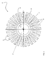
FIG. 1 is a cross-section of a heat exchanger according to an embodiment of the invention; -
FIG. 2 is a cross-section of a heat exchanger according to an embodiment of the invention; -
FIG. 3 is a perspective view of the heat exchanger illustrated inFIG. 2 ; -
FIG. 4 is a side view of a heat exchanger according to an embodiment of the invention; and -
FIG. 5 is a method of manufacturing a heat exchanger according to an embodiment of the invention. - The detailed description explains embodiments of the invention, together with advantages and features, by way of example with reference to the drawings.
- Referring now to the FIGS., a
heat exchanger 20 configured for use with a rotatingcomponent 10, such as a motor driven shaft for example, is illustrated. Theheat exchanger 20 includes a generallycylindrical base 22 having a plurality offins 30 extending generally radially therefrom. Each of the plurality offins 30 is spaced apart from another of the plurality offins 30. In one embodiment, theheat exchanger 20 is substantially axisymmetric about the axis of rotation R of therotating component 10. As illustrated inFIG. 1 , afirst surface 24 of thebase 22 may be positioned adjacent to therotating component 10 such that the plurality offins 30 extends generally outwardly from a second,opposite surface 26 of thebase 22. A generally cylindrical element (not shown) may be arranged adjacent and connected to thedistal ends 31 of thefins 30. In another embodiment, thesecond surface 26 of thebase 22 may be arranged adjacent to therotating component 10 such that the plurality offins 30 extends generally inwardly from thefirst surface 24 of the base as is illustrated inFIG. 2 . - In one embodiment, each of the plurality of
fins 30 is configured to extend generally longitudinally along thebase 22, such as from afirst end 27 to a second,opposite end 29. The plurality offins 30 may, but need not be, substantially identical fromend 27 toend 29 as shown inFIG. 3 . In addition, the size and/or shape of each of the plurality offins 30 may be generally constant. Alternatively, the size and/or shape of at least one of the plurality offins 30 may vary about the periphery of thebase 22 or over the length of the base 22 (FIG. 4 ). In one embodiment, illustrated inFIG. 4 , a portion of the each of the plurality offins 30, such as aninlet end 32 for example, is skewed relative to the axis of rotation R to create a pumping mechanism and enhance the cooling flow C over thefins 30 during rotation of the rotatingmember 10 about axis R. In another embodiment, at least one of the plurality offins 30 may be skewed over the entire length of thefin 30 such that the fin 30 wraps around thecylindrical base 22. - In one embodiment, the
heat exchanger 20 is formed through an additive metal fabrication process that applies energy to a generally powdered material, such as a powered metal, metal alloy, ceramic or composite material for example, to form a shape. Exemplary additive metal fabrication processes include, but are not limited to, direct metal laser sintering (DMLS), selective laser sintering (SLS), and electron beam melting (EBM) for example. - Referring now to
FIG. 5 , amethod 100 of fabricating aheat exchanger 20 is described. Inblock 102, a stereolithography file that describes the surface geometry of theheat exchanger 20 is generated, for example based on a three dimensional model of theheat exchanger 20 created using a computer aided design (CAD) software. The stereolithography file is provided as an input to a pre-processing software configured to slice the surface geometry of theheat exchanger 20 into a plurality of thin layers, as illustrated inblock 104. In one embodiment, because theheat exchanger 20 is substantially axisymmetric, each of the plurality of thin layers will similarly be axisymmetric about the axis of rotation R. The thickness of each of the plurality of thin layers will vary depending on the specific additive metal fabrication process used, as well as the size of theheat exchanger 20. For example, if theheat exchanger 20 is fabricated using direct metal laser sintering, the plurality of layers may have a thickness of about 20 micrometers, whereas if theheat exchanger 20 is fabricated using electron beam melting, the plurality of layers may have a thickness of about 40 micrometers. - In
block 106, after the model of theheat exchanger 20 has been sliced into a plurality of layers, energy from an energy source is applied to a powdered material on a surface, such as a build platform for example. Examples of the energy source, include but are not limited to, an electron beam, a laser, or any other suitable light source known to a person having ordinary skill in the art for example. The energy or heat from the energy source locally melts the powdered material such that the powdered material fuses into a substantially solid part to create a generally two-dimensional section representing a thin layer of theheat exchanger 20. Additional powdered material is arranged on a surface of the fused solid part inblock 108. Similar to block 106, inblock 110, energy from the energy source is again applied to the powered material to form an adjacent thin layer of theheat exchanger 20. The addition of powered material inblock 108 and the application of energy to the powered material inblock 110, is generally repeated until each of the plurality of thin layers of the heat exchanger model has been created. Because the layers of theheat exchanger 20 are built sequentially, each thin layer is integrally formed with at least one adjacent thin layer to form aunitary heat exchanger 20. In one embodiment, theheat exchanger 20 may be heat treated to eliminate residual stresses in theheat exchanger 20, as illustrated inblock 112. In another embodiment, a protective coating may be applied to theheat exchanger 20, inblock 112, based on the intended application of theheat exchanger 20. - By forming a
heat exchanger 20 using an additive metal fabrication process, theheat exchanger 20 may be formed as a single component and does not require the assembly of separate parts, or the rolling and aligning of fins to form an axisymmetric configuration. In addition, fabrication using an additive process is offers significant advantages over conventional methods in both production time and cost. For example, theheat exchanger 20 may be fabricated using materials, such as nickel for example, that would not be suitable using conventional methods because of cost and inefficiencies. In addition, building the heat exchanger by additive manufacturing process eliminates the brazing operation, and therefore the unse of any undesirable materials. Because theheat exchanger 20 is built layer by layer, it is possible to customize aheat exchanger 20 to an application, such as by including non-uniform features or passages that could not previously be cast or machined. For example, thefins 30 of theheat exchanger 20 may be formed with a thickness less than, or considerably more than if theheat exchanger 20 was formed by folding a piece of sheet metal. - While the invention has been described in detail in connection with only a limited number of embodiments, it should be readily understood that the invention is not limited to such disclosed embodiments. Rather, the invention can be modified to incorporate any number of variations, alterations, substitutions or equivalent arrangements not heretofore described, but which are commensurate with the scope of the invention. Additionally, while various embodiments of the invention have been described, it is to be understood that aspects of the invention may include only some of the described embodiments. Accordingly, the invention is not to be seen as limited by the foregoing description, but is only limited by the scope of the appended claims.
Claims (15)
- A method of creating a heat exchanger (20) for use with a rotating component (10) configured to rotate about an axis of rotation (R), the method comprising:generating a stereolithography file including a surface geometry of the heat exchanger (20) that includes a cylindrical base (22) having a plurality of fins (30) extending radially from the base (22),slicing the surface geometry of the stereolithography file into a plurality of axisymmetric layers perpendicular to the axis of rotation (R); andapplying energy from an energy source to a powdered material such that the powdered material fuses to form the plurality of axisymmetric thin layers, wherein each of the axisymmetric thin layers is integrally formed with an adjacent axisymmetric thin layer to create a unitary heat exchanger (20).
- The method according to claim 1, wherein a portion of each of the plurality of fins (30) is skewed relative to the axis of rotation (R).
- The method according to claim 2, wherein a first end (27) of each of the plurality of fins (30) is skewed.
- The method according to claim 2 or 3, wherein the plurality of fins (30) are skewed over an entire length of the heat exchanger (20).
- The method according to any preceding claim, further comprising heat treating the plurality of integrally formed axisymmetric thin layers.
- The method according to any preceding claim, further comprising applying a coating to the plurality of integrally formed axisymmetric thin layers.
- The method according to any preceding claim, wherein the powdered material is selected from metal, metal alloy, ceramic and a composite material.
- A heat exchanger (20) configured for use with a rotating component (10) about an axis of rotation (R), the heat exchanger (200 comprising a generally cylindrical base (22) having a plurality of fins (30) integrally formed with and extending generally radially from the base (22), such that the heat exchanger (20) is substantially axisymmetric about the axis of rotation (R), wherein a portion of each of the plurality of fins (30) is skewed relative to the axis of rotation (R).
- The heat exchanger (20) according to claim 8, wherein the plurality of fins (30) extend generally radially outward from a first surface (26) of the base (22).
- The heat exchanger (20) according to claim 8, wherein the plurality of fins (30) extend generally radially inward from a second surface (24) of the base (22).
- The heat exchanger (20) according to any of claims 8 to 10, wherein the plurality of fins (30) are substantially identical.
- The heat exchanger (20) according to any of claims 8 to 11, wherein the plurality of fins (30) extend from a first end (27) of the base (22) to a second, opposite end (29) of the base (22).
- The heat exchanger (20) according to claim 12, wherein the plurality of fins (30) are skewed about the axis of rotation (R) from the first end (27) to the second end (29).
- The heat exchanger (20) according to any of claims 8 to 13, wherein a size and/or shape of each of the plurality of fins (30) varies from a or the first end (27) of the base (22) to a or the second, opposite end (29) of the base (22).
- The heat exchanger (20) according to any of claims 8 to 14, wherein the plurality of fins (30) are skewed adjacent a or the first end (27) of the base (22).
Applications Claiming Priority (1)
| Application Number | Priority Date | Filing Date | Title |
|---|---|---|---|
| US13/848,356 US20140284038A1 (en) | 2013-03-21 | 2013-03-21 | Heat exchanger design and fabrication |
Publications (3)
| Publication Number | Publication Date |
|---|---|
| EP2781872A1 true EP2781872A1 (en) | 2014-09-24 |
| EP2781872B1 EP2781872B1 (en) | 2022-01-19 |
| EP2781872B8 EP2781872B8 (en) | 2022-02-23 |
Family
ID=50289516
Family Applications (1)
| Application Number | Title | Priority Date | Filing Date |
|---|---|---|---|
| EP14160541.0A Active EP2781872B8 (en) | 2013-03-21 | 2014-03-18 | Heat exchanger design and fabrication |
Country Status (2)
| Country | Link |
|---|---|
| US (1) | US20140284038A1 (en) |
| EP (1) | EP2781872B8 (en) |
Cited By (1)
| Publication number | Priority date | Publication date | Assignee | Title |
|---|---|---|---|---|
| WO2016139019A1 (en) * | 2015-03-05 | 2016-09-09 | Mahle International Gmbh | Heat exchanger, in particular for a motor vehicle |
Families Citing this family (23)
| Publication number | Priority date | Publication date | Assignee | Title |
|---|---|---|---|---|
| US9810150B2 (en) * | 2014-10-21 | 2017-11-07 | United Technologies Corporation | Heat exchanger assembly |
| US10099325B2 (en) | 2015-04-15 | 2018-10-16 | Delavan Inc. | Method for manufacturing a hybrid heat exchanger |
| DE102015007343B4 (en) * | 2015-06-12 | 2017-05-11 | Hosokawa Alpine Aktiengesellschaft | Cooling rollers for roller presses |
| US10495384B2 (en) | 2015-07-30 | 2019-12-03 | General Electric Company | Counter-flow heat exchanger with helical passages |
| US9746257B2 (en) | 2015-08-11 | 2017-08-29 | Hamilton Sundstrand Corporation | Heat exchanger and fabrication |
| US10088250B2 (en) | 2016-01-12 | 2018-10-02 | Hamilton Sundstrand Corporation | Heat exchangers |
| US11293703B2 (en) | 2016-01-12 | 2022-04-05 | Hamilton Sundstrand Corporation | Heat exchangers |
| US10018424B2 (en) * | 2016-02-05 | 2018-07-10 | Hamilton Sundstrand Corporation | Counter spiral tube and shell heat exchanger |
| CN105603364B (en) * | 2016-03-16 | 2018-11-23 | 深圳市华星光电技术有限公司 | Heat-transfer device and vapor deposition crucible |
| US20170356692A1 (en) * | 2016-06-08 | 2017-12-14 | Savannah River Nuclear Solutions, Llc | Finned Heat Exchanger |
| AT518986B1 (en) * | 2016-10-07 | 2018-03-15 | Dipl Ing Thomas Euler Rolle | heat exchangers |
| EP3410054B1 (en) | 2017-05-30 | 2022-10-26 | Ge Avio S.r.l. | Additively manufactured heat exchanger |
| US20190215984A1 (en) * | 2018-01-09 | 2019-07-11 | Aptiv Technologies Limited | Wireless device charger with cooling device |
| US10654103B2 (en) | 2018-09-20 | 2020-05-19 | General Electric Company | Method of manufacturing a fin structure for heat exchanger |
| BR112022005763A2 (en) | 2019-09-27 | 2022-06-21 | Univ Marquette | Stator winding with integrated cooling |
| DE102019131323A1 (en) * | 2019-11-20 | 2021-05-20 | Schmöle GmbH | Heat exchangers and processes for their manufacture or design |
| US11802736B2 (en) | 2020-07-29 | 2023-10-31 | Hamilton Sundstrand Corporation | Annular heat exchanger |
| CN113199750B (en) * | 2021-06-21 | 2022-01-07 | 安庆瑞迈特科技有限公司 | Efficient 3D printing method of collimator |
| US11927402B2 (en) * | 2021-07-13 | 2024-03-12 | The Boeing Company | Heat transfer device with nested layers of helical fluid channels |
| US12212217B2 (en) * | 2022-05-13 | 2025-01-28 | Wisconsin Alumni Research Foundation | System and method for electric machine cooling |
| US20240044587A1 (en) * | 2022-08-05 | 2024-02-08 | Hamilton Sundstrand Corporation | Heat exchanger with heat transfer augmentation features |
| US11982499B2 (en) | 2022-08-05 | 2024-05-14 | Hamilton Sundstrand Corporation | Heat exchanger with heat transfer augmentation features |
| CN115864694B (en) * | 2022-11-04 | 2025-08-01 | 南京航空航天大学 | Axial ventilation convection heat exchanger manufactured by additive |
Citations (3)
| Publication number | Priority date | Publication date | Assignee | Title |
|---|---|---|---|---|
| SU1139962A1 (en) * | 1983-12-26 | 1985-02-15 | Московский Ордена Трудового Красного Знамени Институт Химического Машиностроения | Heat-exchange pipe |
| WO2001002160A1 (en) * | 1999-07-07 | 2001-01-11 | Optomec Design Company | Method for providing features enabling thermal management in complex three-dimensional structures |
| JP2005077035A (en) * | 2003-09-02 | 2005-03-24 | Usui Kokusai Sangyo Kaisha Ltd | Corrosion resisting heat transfer tube |
Family Cites Families (25)
| Publication number | Priority date | Publication date | Assignee | Title |
|---|---|---|---|---|
| US102160A (en) * | 1870-04-19 | John h | ||
| US1030203A (en) * | 1911-07-31 | 1912-06-18 | Christen Paulsen | Pasteurizing apparatus. |
| US1139962A (en) * | 1912-10-21 | 1915-05-18 | Michael D Franey | Wrist-pin fastening. |
| US1583333A (en) * | 1920-06-08 | 1926-05-04 | Bigum Hans Jphirgen Jensen | Rotary cooling drum |
| US2764704A (en) * | 1954-06-10 | 1956-09-25 | Alfred A Wolf | Electric motor provided with cooling means |
| US2943845A (en) * | 1957-10-23 | 1960-07-05 | Jaklitsch Franz | Heat exchanger for viscous fluids |
| CH412952A (en) * | 1964-07-27 | 1966-05-15 | Buss Ag | Rolling element-filled heat exchanger and method of operating the same |
| US5445216A (en) * | 1994-03-10 | 1995-08-29 | Cannata; Antonio | Heat exchanger |
| TW327205B (en) * | 1995-06-19 | 1998-02-21 | Hitachi Ltd | Heat exchanger |
| US5655599A (en) * | 1995-06-21 | 1997-08-12 | Gas Research Institute | Radiant tubes having internal fins |
| AUPN811396A0 (en) * | 1996-02-16 | 1996-03-07 | Bhp Steel (Jla) Pty Limited | Roll cooling structure for twin roll continuous caster |
| US5983993A (en) * | 1996-08-30 | 1999-11-16 | International Paper Company | High production chill roll |
| US5884691A (en) * | 1997-09-03 | 1999-03-23 | Batchelder; John Samual | Fluid transmissive moderated flow resistance heat transfer unit |
| US6695038B2 (en) * | 1999-09-02 | 2004-02-24 | Advanced Rotary Systems, Llc | Heat exchanger type fan |
| US20010024733A1 (en) * | 1999-09-10 | 2001-09-27 | Kasprzyk Martin R. | Insert for a radiant tube |
| US6657862B2 (en) * | 2001-09-10 | 2003-12-02 | Intel Corporation | Radial folded fin heat sinks and methods of making and using same |
| TWI267337B (en) * | 2003-05-14 | 2006-11-21 | Inventor Prec Co Ltd | Heat sink |
| DE10347180A1 (en) * | 2003-10-10 | 2005-05-12 | Modine Mfg Co | Heat exchangers, in particular for motor vehicles |
| FR2865080B1 (en) * | 2003-12-19 | 2006-04-28 | Telma | SIMPLE RADIAL ELECTROMAGNETIC RETARDER COMPRISING MEANS FOR PROVIDING A VENTILATION |
| SE527867C2 (en) * | 2004-11-12 | 2006-06-27 | Bjoern Gudmunsson | Cooling installation |
| US20070012426A1 (en) * | 2005-07-14 | 2007-01-18 | Pratt & Whitney Canada Corp. | High efficiency high turbulence heat exchanger |
| US8172738B2 (en) * | 2006-01-18 | 2012-05-08 | 3M Innovative Properties Company | Dead-shaft roller with aerostatic rotary union |
| US8162040B2 (en) * | 2006-03-10 | 2012-04-24 | Spinworks, LLC | Heat exchanging insert and method for fabricating same |
| CN100473937C (en) * | 2006-10-24 | 2009-04-01 | 张伟君 | High-tech aluminium composite pipe special for environment-friendly energy-saving heating system |
| US7810552B2 (en) * | 2006-12-20 | 2010-10-12 | The Boeing Company | Method of making a heat exchanger |
-
2013
- 2013-03-21 US US13/848,356 patent/US20140284038A1/en not_active Abandoned
-
2014
- 2014-03-18 EP EP14160541.0A patent/EP2781872B8/en active Active
Patent Citations (3)
| Publication number | Priority date | Publication date | Assignee | Title |
|---|---|---|---|---|
| SU1139962A1 (en) * | 1983-12-26 | 1985-02-15 | Московский Ордена Трудового Красного Знамени Институт Химического Машиностроения | Heat-exchange pipe |
| WO2001002160A1 (en) * | 1999-07-07 | 2001-01-11 | Optomec Design Company | Method for providing features enabling thermal management in complex three-dimensional structures |
| JP2005077035A (en) * | 2003-09-02 | 2005-03-24 | Usui Kokusai Sangyo Kaisha Ltd | Corrosion resisting heat transfer tube |
Cited By (1)
| Publication number | Priority date | Publication date | Assignee | Title |
|---|---|---|---|---|
| WO2016139019A1 (en) * | 2015-03-05 | 2016-09-09 | Mahle International Gmbh | Heat exchanger, in particular for a motor vehicle |
Also Published As
| Publication number | Publication date |
|---|---|
| EP2781872B1 (en) | 2022-01-19 |
| US20140284038A1 (en) | 2014-09-25 |
| EP2781872B8 (en) | 2022-02-23 |
Similar Documents
| Publication | Publication Date | Title |
|---|---|---|
| EP2781872B1 (en) | Heat exchanger design and fabrication | |
| US10434575B2 (en) | Additively manufactured heat exchanger including flow turbulators defining internal fluid passageways | |
| JP7040707B2 (en) | Additional manufactured heat exchanger | |
| US10823201B2 (en) | Engine heat exchanger and method of forming | |
| US9713843B2 (en) | Method for additively constructing internal channels | |
| EP3486595A1 (en) | Contoured wall heat exchanger | |
| US20170067579A1 (en) | Design of tortuous path control valve trim | |
| EP3392588B1 (en) | Heat exchanger | |
| US20080149299A1 (en) | Method of using minimal surfaces and minimal skeletons to make heat exchanger components | |
| US20170131034A1 (en) | Heat exchanger | |
| EP3869139A1 (en) | Heat exchanger with undulating plates | |
| CA2948252C (en) | Turbine airfoil with passive morphing structure | |
| WO2018111396A1 (en) | Additively manufactured gearbox with integral heat exchanger | |
| EP3018349A2 (en) | Rotary screw compressor | |
| US20190211949A1 (en) | Additively Manufactured Tube Array | |
| JP2022008275A (en) | Heat exchanger | |
| JP2017072127A (en) | Article and method for forming article | |
| EP4145081B1 (en) | Layered diffuser channel heat exchanger | |
| CN112423914A (en) | Blank for a line assembly, in particular for an electric inductor | |
| CA2796862A1 (en) | Heat exchanger with fins and method for forming same |
Legal Events
| Date | Code | Title | Description |
|---|---|---|---|
| PUAI | Public reference made under article 153(3) epc to a published international application that has entered the european phase |
Free format text: ORIGINAL CODE: 0009012 |
|
| 17P | Request for examination filed |
Effective date: 20140318 |
|
| AK | Designated contracting states |
Kind code of ref document: A1 Designated state(s): AL AT BE BG CH CY CZ DE DK EE ES FI FR GB GR HR HU IE IS IT LI LT LU LV MC MK MT NL NO PL PT RO RS SE SI SK SM TR |
|
| AX | Request for extension of the european patent |
Extension state: BA ME |
|
| R17P | Request for examination filed (corrected) |
Effective date: 20150324 |
|
| RBV | Designated contracting states (corrected) |
Designated state(s): AL AT BE BG CH CY CZ DE DK EE ES FI FR GB GR HR HU IE IS IT LI LT LU LV MC MK MT NL NO PL PT RO RS SE SI SK SM TR |
|
| STAA | Information on the status of an ep patent application or granted ep patent |
Free format text: STATUS: EXAMINATION IS IN PROGRESS |
|
| 17Q | First examination report despatched |
Effective date: 20180622 |
|
| GRAP | Despatch of communication of intention to grant a patent |
Free format text: ORIGINAL CODE: EPIDOSNIGR1 |
|
| STAA | Information on the status of an ep patent application or granted ep patent |
Free format text: STATUS: GRANT OF PATENT IS INTENDED |
|
| INTG | Intention to grant announced |
Effective date: 20210208 |
|
| GRAJ | Information related to disapproval of communication of intention to grant by the applicant or resumption of examination proceedings by the epo deleted |
Free format text: ORIGINAL CODE: EPIDOSDIGR1 |
|
| STAA | Information on the status of an ep patent application or granted ep patent |
Free format text: STATUS: EXAMINATION IS IN PROGRESS |
|
| GRAP | Despatch of communication of intention to grant a patent |
Free format text: ORIGINAL CODE: EPIDOSNIGR1 |
|
| STAA | Information on the status of an ep patent application or granted ep patent |
Free format text: STATUS: GRANT OF PATENT IS INTENDED |
|
| INTC | Intention to grant announced (deleted) | ||
| INTG | Intention to grant announced |
Effective date: 20210802 |
|
| RIN1 | Information on inventor provided before grant (corrected) |
Inventor name: VEDULA, VENKATA R. Inventor name: TELAKOWSKI, ROBERT |
|
| GRAS | Grant fee paid |
Free format text: ORIGINAL CODE: EPIDOSNIGR3 |
|
| GRAA | (expected) grant |
Free format text: ORIGINAL CODE: 0009210 |
|
| STAA | Information on the status of an ep patent application or granted ep patent |
Free format text: STATUS: THE PATENT HAS BEEN GRANTED |
|
| AK | Designated contracting states |
Kind code of ref document: B1 Designated state(s): AL AT BE BG CH CY CZ DE DK EE ES FI FR GB GR HR HU IE IS IT LI LT LU LV MC MK MT NL NO PL PT RO RS SE SI SK SM TR |
|
| REG | Reference to a national code |
Ref country code: GB Ref legal event code: FG4D |
|
| REG | Reference to a national code |
Ref country code: DE Ref legal event code: R081 Ref document number: 602014082206 Country of ref document: DE Owner name: HAMILTON SUNDSTRAND CORPORATION, CHARLOTTE, US Free format text: FORMER OWNER: HAMILTON SUNDSTRAND CORPORATION, WINDSOR LOCKS, CT, US |
|
| REG | Reference to a national code |
Ref country code: CH Ref legal event code: PK Free format text: BERICHTIGUNG B8 Ref country code: CH Ref legal event code: EP |
|
| REG | Reference to a national code |
Ref country code: DE Ref legal event code: R096 Ref document number: 602014082206 Country of ref document: DE |
|
| REG | Reference to a national code |
Ref country code: AT Ref legal event code: REF Ref document number: 1464039 Country of ref document: AT Kind code of ref document: T Effective date: 20220215 |
|
| RAP4 | Party data changed (patent owner data changed or rights of a patent transferred) |
Owner name: HAMILTON SUNDSTRAND CORPORATION |
|
| REG | Reference to a national code |
Ref country code: IE Ref legal event code: FG4D |
|
| REG | Reference to a national code |
Ref country code: LT Ref legal event code: MG9D |
|
| REG | Reference to a national code |
Ref country code: NL Ref legal event code: MP Effective date: 20220119 |
|
| REG | Reference to a national code |
Ref country code: AT Ref legal event code: MK05 Ref document number: 1464039 Country of ref document: AT Kind code of ref document: T Effective date: 20220119 |
|
| PG25 | Lapsed in a contracting state [announced via postgrant information from national office to epo] |
Ref country code: NL Free format text: LAPSE BECAUSE OF FAILURE TO SUBMIT A TRANSLATION OF THE DESCRIPTION OR TO PAY THE FEE WITHIN THE PRESCRIBED TIME-LIMIT Effective date: 20220119 |
|
| PG25 | Lapsed in a contracting state [announced via postgrant information from national office to epo] |
Ref country code: SK Free format text: LAPSE BECAUSE OF FAILURE TO SUBMIT A TRANSLATION OF THE DESCRIPTION OR TO PAY THE FEE WITHIN THE PRESCRIBED TIME-LIMIT Effective date: 20220119 Ref country code: SE Free format text: LAPSE BECAUSE OF FAILURE TO SUBMIT A TRANSLATION OF THE DESCRIPTION OR TO PAY THE FEE WITHIN THE PRESCRIBED TIME-LIMIT Effective date: 20220119 Ref country code: RS Free format text: LAPSE BECAUSE OF FAILURE TO SUBMIT A TRANSLATION OF THE DESCRIPTION OR TO PAY THE FEE WITHIN THE PRESCRIBED TIME-LIMIT Effective date: 20220119 Ref country code: PT Free format text: LAPSE BECAUSE OF FAILURE TO SUBMIT A TRANSLATION OF THE DESCRIPTION OR TO PAY THE FEE WITHIN THE PRESCRIBED TIME-LIMIT Effective date: 20220519 Ref country code: NO Free format text: LAPSE BECAUSE OF FAILURE TO SUBMIT A TRANSLATION OF THE DESCRIPTION OR TO PAY THE FEE WITHIN THE PRESCRIBED TIME-LIMIT Effective date: 20220419 Ref country code: LT Free format text: LAPSE BECAUSE OF FAILURE TO SUBMIT A TRANSLATION OF THE DESCRIPTION OR TO PAY THE FEE WITHIN THE PRESCRIBED TIME-LIMIT Effective date: 20220119 Ref country code: HR Free format text: LAPSE BECAUSE OF FAILURE TO SUBMIT A TRANSLATION OF THE DESCRIPTION OR TO PAY THE FEE WITHIN THE PRESCRIBED TIME-LIMIT Effective date: 20220119 Ref country code: ES Free format text: LAPSE BECAUSE OF FAILURE TO SUBMIT A TRANSLATION OF THE DESCRIPTION OR TO PAY THE FEE WITHIN THE PRESCRIBED TIME-LIMIT Effective date: 20220119 Ref country code: BG Free format text: LAPSE BECAUSE OF FAILURE TO SUBMIT A TRANSLATION OF THE DESCRIPTION OR TO PAY THE FEE WITHIN THE PRESCRIBED TIME-LIMIT Effective date: 20220419 |
|
| PG25 | Lapsed in a contracting state [announced via postgrant information from national office to epo] |
Ref country code: PL Free format text: LAPSE BECAUSE OF FAILURE TO SUBMIT A TRANSLATION OF THE DESCRIPTION OR TO PAY THE FEE WITHIN THE PRESCRIBED TIME-LIMIT Effective date: 20220119 Ref country code: LV Free format text: LAPSE BECAUSE OF FAILURE TO SUBMIT A TRANSLATION OF THE DESCRIPTION OR TO PAY THE FEE WITHIN THE PRESCRIBED TIME-LIMIT Effective date: 20220119 Ref country code: GR Free format text: LAPSE BECAUSE OF FAILURE TO SUBMIT A TRANSLATION OF THE DESCRIPTION OR TO PAY THE FEE WITHIN THE PRESCRIBED TIME-LIMIT Effective date: 20220420 Ref country code: FI Free format text: LAPSE BECAUSE OF FAILURE TO SUBMIT A TRANSLATION OF THE DESCRIPTION OR TO PAY THE FEE WITHIN THE PRESCRIBED TIME-LIMIT Effective date: 20220119 Ref country code: AT Free format text: LAPSE BECAUSE OF FAILURE TO SUBMIT A TRANSLATION OF THE DESCRIPTION OR TO PAY THE FEE WITHIN THE PRESCRIBED TIME-LIMIT Effective date: 20220119 |
|
| PG25 | Lapsed in a contracting state [announced via postgrant information from national office to epo] |
Ref country code: IS Free format text: LAPSE BECAUSE OF FAILURE TO SUBMIT A TRANSLATION OF THE DESCRIPTION OR TO PAY THE FEE WITHIN THE PRESCRIBED TIME-LIMIT Effective date: 20220519 |
|
| REG | Reference to a national code |
Ref country code: DE Ref legal event code: R119 Ref document number: 602014082206 Country of ref document: DE |
|
| PG25 | Lapsed in a contracting state [announced via postgrant information from national office to epo] |
Ref country code: SM Free format text: LAPSE BECAUSE OF FAILURE TO SUBMIT A TRANSLATION OF THE DESCRIPTION OR TO PAY THE FEE WITHIN THE PRESCRIBED TIME-LIMIT Effective date: 20220119 Ref country code: RO Free format text: LAPSE BECAUSE OF FAILURE TO SUBMIT A TRANSLATION OF THE DESCRIPTION OR TO PAY THE FEE WITHIN THE PRESCRIBED TIME-LIMIT Effective date: 20220119 Ref country code: MC Free format text: LAPSE BECAUSE OF FAILURE TO SUBMIT A TRANSLATION OF THE DESCRIPTION OR TO PAY THE FEE WITHIN THE PRESCRIBED TIME-LIMIT Effective date: 20220119 Ref country code: EE Free format text: LAPSE BECAUSE OF FAILURE TO SUBMIT A TRANSLATION OF THE DESCRIPTION OR TO PAY THE FEE WITHIN THE PRESCRIBED TIME-LIMIT Effective date: 20220119 Ref country code: DK Free format text: LAPSE BECAUSE OF FAILURE TO SUBMIT A TRANSLATION OF THE DESCRIPTION OR TO PAY THE FEE WITHIN THE PRESCRIBED TIME-LIMIT Effective date: 20220119 Ref country code: CZ Free format text: LAPSE BECAUSE OF FAILURE TO SUBMIT A TRANSLATION OF THE DESCRIPTION OR TO PAY THE FEE WITHIN THE PRESCRIBED TIME-LIMIT Effective date: 20220119 |
|
| REG | Reference to a national code |
Ref country code: CH Ref legal event code: PL |
|
| PLBE | No opposition filed within time limit |
Free format text: ORIGINAL CODE: 0009261 |
|
| STAA | Information on the status of an ep patent application or granted ep patent |
Free format text: STATUS: NO OPPOSITION FILED WITHIN TIME LIMIT |
|
| PG25 | Lapsed in a contracting state [announced via postgrant information from national office to epo] |
Ref country code: AL Free format text: LAPSE BECAUSE OF FAILURE TO SUBMIT A TRANSLATION OF THE DESCRIPTION OR TO PAY THE FEE WITHIN THE PRESCRIBED TIME-LIMIT Effective date: 20220119 |
|
| REG | Reference to a national code |
Ref country code: BE Ref legal event code: MM Effective date: 20220331 |
|
| 26N | No opposition filed |
Effective date: 20221020 |
|
| PG25 | Lapsed in a contracting state [announced via postgrant information from national office to epo] |
Ref country code: LU Free format text: LAPSE BECAUSE OF NON-PAYMENT OF DUE FEES Effective date: 20220318 Ref country code: LI Free format text: LAPSE BECAUSE OF NON-PAYMENT OF DUE FEES Effective date: 20220331 Ref country code: IE Free format text: LAPSE BECAUSE OF NON-PAYMENT OF DUE FEES Effective date: 20220318 Ref country code: DE Free format text: LAPSE BECAUSE OF NON-PAYMENT OF DUE FEES Effective date: 20221001 Ref country code: CH Free format text: LAPSE BECAUSE OF NON-PAYMENT OF DUE FEES Effective date: 20220331 |
|
| PG25 | Lapsed in a contracting state [announced via postgrant information from national office to epo] |
Ref country code: SI Free format text: LAPSE BECAUSE OF FAILURE TO SUBMIT A TRANSLATION OF THE DESCRIPTION OR TO PAY THE FEE WITHIN THE PRESCRIBED TIME-LIMIT Effective date: 20220119 Ref country code: BE Free format text: LAPSE BECAUSE OF NON-PAYMENT OF DUE FEES Effective date: 20220331 |
|
| P01 | Opt-out of the competence of the unified patent court (upc) registered |
Effective date: 20230522 |
|
| PG25 | Lapsed in a contracting state [announced via postgrant information from national office to epo] |
Ref country code: IT Free format text: LAPSE BECAUSE OF FAILURE TO SUBMIT A TRANSLATION OF THE DESCRIPTION OR TO PAY THE FEE WITHIN THE PRESCRIBED TIME-LIMIT Effective date: 20220119 |
|
| PG25 | Lapsed in a contracting state [announced via postgrant information from national office to epo] |
Ref country code: HU Free format text: LAPSE BECAUSE OF FAILURE TO SUBMIT A TRANSLATION OF THE DESCRIPTION OR TO PAY THE FEE WITHIN THE PRESCRIBED TIME-LIMIT; INVALID AB INITIO Effective date: 20140318 |
|
| PG25 | Lapsed in a contracting state [announced via postgrant information from national office to epo] |
Ref country code: MK Free format text: LAPSE BECAUSE OF FAILURE TO SUBMIT A TRANSLATION OF THE DESCRIPTION OR TO PAY THE FEE WITHIN THE PRESCRIBED TIME-LIMIT Effective date: 20220119 Ref country code: CY Free format text: LAPSE BECAUSE OF FAILURE TO SUBMIT A TRANSLATION OF THE DESCRIPTION OR TO PAY THE FEE WITHIN THE PRESCRIBED TIME-LIMIT Effective date: 20220119 |
|
| PG25 | Lapsed in a contracting state [announced via postgrant information from national office to epo] |
Ref country code: TR Free format text: LAPSE BECAUSE OF FAILURE TO SUBMIT A TRANSLATION OF THE DESCRIPTION OR TO PAY THE FEE WITHIN THE PRESCRIBED TIME-LIMIT Effective date: 20220119 |
|
| PG25 | Lapsed in a contracting state [announced via postgrant information from national office to epo] |
Ref country code: MT Free format text: LAPSE BECAUSE OF FAILURE TO SUBMIT A TRANSLATION OF THE DESCRIPTION OR TO PAY THE FEE WITHIN THE PRESCRIBED TIME-LIMIT Effective date: 20220119 |
|
| PGFP | Annual fee paid to national office [announced via postgrant information from national office to epo] |
Ref country code: GB Payment date: 20260219 Year of fee payment: 13 |
|
| PGFP | Annual fee paid to national office [announced via postgrant information from national office to epo] |
Ref country code: FR Payment date: 20260219 Year of fee payment: 13 |