EP2781824A1 - A driver for a light source - Google Patents
A driver for a light source Download PDFInfo
- Publication number
- EP2781824A1 EP2781824A1 EP13159725.4A EP13159725A EP2781824A1 EP 2781824 A1 EP2781824 A1 EP 2781824A1 EP 13159725 A EP13159725 A EP 13159725A EP 2781824 A1 EP2781824 A1 EP 2781824A1
- Authority
- EP
- European Patent Office
- Prior art keywords
- lighting
- program
- period
- duration
- lighting program
- Prior art date
- Legal status (The legal status is an assumption and is not a legal conclusion. Google has not performed a legal analysis and makes no representation as to the accuracy of the status listed.)
- Granted
Links
Images


Classifications
-
- H—ELECTRICITY
- H05—ELECTRIC TECHNIQUES NOT OTHERWISE PROVIDED FOR
- H05B—ELECTRIC HEATING; ELECTRIC LIGHT SOURCES NOT OTHERWISE PROVIDED FOR; CIRCUIT ARRANGEMENTS FOR ELECTRIC LIGHT SOURCES, IN GENERAL
- H05B47/00—Circuit arrangements for operating light sources in general, i.e. where the type of light source is not relevant
- H05B47/10—Controlling the light source
- H05B47/175—Controlling the light source by remote control
- H05B47/185—Controlling the light source by remote control via power line carrier transmission
-
- H—ELECTRICITY
- H05—ELECTRIC TECHNIQUES NOT OTHERWISE PROVIDED FOR
- H05B—ELECTRIC HEATING; ELECTRIC LIGHT SOURCES NOT OTHERWISE PROVIDED FOR; CIRCUIT ARRANGEMENTS FOR ELECTRIC LIGHT SOURCES, IN GENERAL
- H05B41/00—Circuit arrangements or apparatus for igniting or operating discharge lamps
- H05B41/14—Circuit arrangements
- H05B41/36—Controlling
- H05B41/38—Controlling the intensity of light
-
- H—ELECTRICITY
- H05—ELECTRIC TECHNIQUES NOT OTHERWISE PROVIDED FOR
- H05B—ELECTRIC HEATING; ELECTRIC LIGHT SOURCES NOT OTHERWISE PROVIDED FOR; CIRCUIT ARRANGEMENTS FOR ELECTRIC LIGHT SOURCES, IN GENERAL
- H05B45/00—Circuit arrangements for operating light-emitting diodes [LED]
- H05B45/50—Circuit arrangements for operating light-emitting diodes [LED] responsive to malfunctions or undesirable behaviour of LEDs; responsive to LED life; Protective circuits
- H05B45/59—Circuit arrangements for operating light-emitting diodes [LED] responsive to malfunctions or undesirable behaviour of LEDs; responsive to LED life; Protective circuits for reducing or suppressing flicker or glow effects
-
- H—ELECTRICITY
- H05—ELECTRIC TECHNIQUES NOT OTHERWISE PROVIDED FOR
- H05B—ELECTRIC HEATING; ELECTRIC LIGHT SOURCES NOT OTHERWISE PROVIDED FOR; CIRCUIT ARRANGEMENTS FOR ELECTRIC LIGHT SOURCES, IN GENERAL
- H05B47/00—Circuit arrangements for operating light sources in general, i.e. where the type of light source is not relevant
- H05B47/10—Controlling the light source
- H05B47/16—Controlling the light source by timing means
-
- H—ELECTRICITY
- H05—ELECTRIC TECHNIQUES NOT OTHERWISE PROVIDED FOR
- H05B—ELECTRIC HEATING; ELECTRIC LIGHT SOURCES NOT OTHERWISE PROVIDED FOR; CIRCUIT ARRANGEMENTS FOR ELECTRIC LIGHT SOURCES, IN GENERAL
- H05B47/00—Circuit arrangements for operating light sources in general, i.e. where the type of light source is not relevant
- H05B47/10—Controlling the light source
- H05B47/17—Operational modes, e.g. switching from manual to automatic mode or prohibiting specific operations
-
- H—ELECTRICITY
- H05—ELECTRIC TECHNIQUES NOT OTHERWISE PROVIDED FOR
- H05B—ELECTRIC HEATING; ELECTRIC LIGHT SOURCES NOT OTHERWISE PROVIDED FOR; CIRCUIT ARRANGEMENTS FOR ELECTRIC LIGHT SOURCES, IN GENERAL
- H05B45/00—Circuit arrangements for operating light-emitting diodes [LED]
- H05B45/30—Driver circuits
- H05B45/31—Phase-control circuits
-
- H—ELECTRICITY
- H05—ELECTRIC TECHNIQUES NOT OTHERWISE PROVIDED FOR
- H05B—ELECTRIC HEATING; ELECTRIC LIGHT SOURCES NOT OTHERWISE PROVIDED FOR; CIRCUIT ARRANGEMENTS FOR ELECTRIC LIGHT SOURCES, IN GENERAL
- H05B45/00—Circuit arrangements for operating light-emitting diodes [LED]
- H05B45/30—Driver circuits
- H05B45/37—Converter circuits
- H05B45/3725—Switched mode power supply [SMPS]
-
- H—ELECTRICITY
- H05—ELECTRIC TECHNIQUES NOT OTHERWISE PROVIDED FOR
- H05B—ELECTRIC HEATING; ELECTRIC LIGHT SOURCES NOT OTHERWISE PROVIDED FOR; CIRCUIT ARRANGEMENTS FOR ELECTRIC LIGHT SOURCES, IN GENERAL
- H05B47/00—Circuit arrangements for operating light sources in general, i.e. where the type of light source is not relevant
- H05B47/10—Controlling the light source
- H05B47/175—Controlling the light source by remote control
- H05B47/196—Controlling the light source by remote control characterised by user interface arrangements
Definitions
- the invention relates to control of operation of one or more light sources.
- embodiments of the invention relate to a driver that is able to select a lighting program and to control operation of one or more light sources accordingly, as well as to a method and to a computer program for carrying out the selection and control.
- outdoor lighting provided for public places such as for towns, cities or districts thereof are operated by light sensor based or clock/timer based control systems for switching the lights on or off.
- Such an arrangement may involve issuing control signals e.g. via dedicated control cables or by employing power-line communication (PLC) techniques to one or more relays in a lightning cabinet, which relays in turn pass the operating power to one or more lights sources accordingly.
- PLC power-line communication
- Such systems typically only allow switching the light sources on or off but do not provide e.g. dimming capabilities.
- More advanced systems may allow control of lighting by a PLC technique, via a wireless connection or by employing dedicated control cables. While such systems may provide rather versatile possibilities for controlling dimming (and other) behavior of lighting, on the other hand in many cases they provide a level of sophistication greatly exceeding that required for control of lighting of public places and hence incur unnecessarily high costs and possibly also reliability problems.
- an apparatus for driving one or more light sources comprises a monitoring portion configured to observe durations of active periods, wherein an active period corresponds to a continuous period of operating power being supplied to the apparatus, a mode setting portion configured to select one of a plurality of lighting programs for the apparatus in accordance with the observed durations of one or more active periods, wherein a lighting program defines the desired characteristics of light provided by the one or more light sources as a function of time for a subsequent active period, and a control portion configured to, in response to an active period, control provision of operating power from the apparatus to the one or more light sources in accordance with the most recently selected lighting program.
- a method for driving one or more light sources comprises observing durations of active periods, wherein an active period corresponds to a continuous period of operating power being supplied to a driver apparatus, selecting one of a plurality of lighting programs for the driver apparatus in accordance with the observed durations of one or more active periods, wherein a lighting program defines the desired characteristics of light provided by the one or more light sources as a function of time for a subsequent active period, and controlling, in response to an active period, provision of operating power from the driver apparatus to the one or more light sources in accordance with the most recently selected lighting program.
- a computer program for driving a light source comprises one or more sequences of one or more instructions which, when executed by one or more processors, cause an apparatus at least to observe durations of active periods, wherein an active period corresponds to a continuous period of operating power being supplied to the driver apparatus, to select one of a plurality of lighting programs for the driver apparatus in accordance with the observed durations of one or more active periods, wherein a lighting program defines the desired characteristics of light provided by the one or more light sources as a function of time for a subsequent active period and to control, in response to an active period, provision of operating power from the driver apparatus to the one or more light sources in accordance with the most recently selected lighting program.
- the computer program may be embodied on a volatile or a non-volatile computer-readable record medium, for example as a computer program product comprising at least one computer readable non-transitory medium having program code stored thereon, the program code, which when executed by an apparatus, causes the apparatus at least to perform the operations described hereinbefore for the computer program in accordance with an example embodiment.
- each of the drivers 130, 130' may be arranged to control one or more respective light sources 140, 140'.
- the switching entity 120 instead of controlling power supply to one or two drivers 130, 130', the switching entity 120 generalizes into one arranged to control power supply to one or more drivers 130, 130', each arranged to control respective one or more light sources 140, 140'.
- control entity 110 may be arranged to control the power supply to the light sources 140, 140' by controlling one or more switching entities 120, each switching entity arranged to control power supply to respective one or more drivers 130, 130' and each of the one or more drivers 130, 130' arranged to control respective one or more light sources 140, 140'.
- the control entity 110 may comprise for example one or more user-operable switches that can be employed to manually control issuing one or more controls signals to the switching entity 120, consequently resulting in the switching entity 120 to supply operating power to the one or more drivers 130, 130' in order to the drivers 130, 130' to switch the operating power to the respective one or more light sources 140, 140', i.e. to turn the lights on or off.
- the one or more control signals may be provided to the switching entity 120 e.g. via dedicated control cables or by employing a PLC technique.
- the one or more control signals may be provided to the switching entity over a wireless link, e.g. one based on a cellular communication technique such as GSM.
- control entity 110 may comprise an automated control arrangement comprising one or more light sensors arranged to issue the one or more control signals that cause turning the lights on and/or off in accordance with the observed level of ambient light.
- an automated control arrangement may comprise one or more timers that may be arranged to issue the one or more control signals that cause turning the lights on and/or off according to a predetermined rule, e.g. in order to provide lighting for a period of desired duration starting at a desired point of time.
- a sensor arrangement or a timer arrangement aims to automatically control the lights to be turned on for the time of the day when there is little or no daylight available.
- the control entity 110 may be arranged to employ a combination of control means, e.g. a combination of the user-operable switch, one or more light sensor and/or one or more timers, for example such that after manually controlling to switch the lights on, the lights will be turned off after a desired period of time and/or in response to observed level of ambient light exceeding a predetermined threshold level.
- control means e.g. a combination of the user-operable switch, one or more light sensor and/or one or more timers, for example such that after manually controlling to switch the lights on, the lights will be turned off after a desired period of time and/or in response to observed level of ambient light exceeding a predetermined threshold level.
- the one or more control signals causing the lights to be switched on may be issued in response to observed level of ambient light falling below a predetermined threshold and subsequently one or more control signals causing the lights to be switched off are issued after a predetermined period of time.
- control entity 110 may be arranged to issue the one or more control signals to several switching entities 120. Such an arrangement may be useful e.g. in relative large scale lighting systems or arrangements covering a plurality of public places such as parks, streets, districts of towns/cities etc. In smaller scale lighting systems or arrangements, such as apartment buildings and private houses, the control entity 110 may be omitted an a user may directly operate the switching entity 120 e.g. via a user-operable switch or a corresponding arrangement provided in the switching entity 120.
- the switching entity 120 may comprise for example one or more relays, each relay arranged to control supply of operating power to one or more drivers 130, 130' coupled thereto.
- the operating power is obtained from an external power supply or power source, typically from mains electricity.
- the driver 130, 130' is preferably capable of adjusting the characteristics of light provided by the respective one or more light sources 140, 140' it is arranged control.
- the adjustment of characteristics may comprise, for example, adjustment of the light intensity, the adjustment of color of light and/or the adjustment of the color temperature of light provided by the respective one or more light sources 140, 140'.
- the adjustment may be provided e.g. on basis of one or more control signals received from the switching entity 120.
- the driver 130, 130' may be for example a light emitting diode (LED) driver and, consequently, the respective one or more light sources 140, 140' the driver 130, 130' is arranged to control comprise LED light sources.
- LED light emitting diode
- the driver 130, 130' may comprise a driver for a high-intensity discharge (HID) lamp, such as a sodium vapor lamp or a mercury vapor lamp and, consequently, the one respective one or more light sources 140, 140' are HID lamps of a corresponding type.
- HID high-intensity discharge
- any light sources 140, 140' or any combination of light sources 140, 140' that enable adjustment of light characteristics thereof may be employed together with a driver 130, 130' of respective type.
- the driver 130, 130' is arranged to control operation of respective two or more light sources 140, 140'
- the two or more light sources 140, 140' may be arranged into one or more luminaires. Consequently, the driver 130, 130' may be configured to control light sources of one or more luminaires.
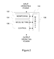
- FIG. 2 schematically illustrates the driver 130, 130'.
- the driver 130, 130' comprises a monitoring portion 132 for observing durations of periods of operating power being supplied to the driver 130, 130', a mode setting portion 134 for adjusting the operation of the driver 130, 130' and a control portion 136 for controlling the operation of the one or more light sources 140.
- the driver 130, 130' may further comprise a memory 138 or the driver 130, 130' may otherwise have access to a memory, either in the driver apparatus or in another entity connected or coupled to the driver 130, 130'.
- One or more of the monitoring portion 132, the mode setting portion 134 and the control portion 136 may be configured to read from and/or to write to the memory 138 (or to/from a memory accessible by the driver 130 but provided outside the driver 130, 130').
- the driver 130, 130' may be provided e.g. in a driver apparatus.
- the driver 130, 130' and/or the driver apparatus is provided with means for receiving the operating power and means for providing operating power to the one or more light sources 140, 140'. Consequently, the driver apparatus may be provided with an arrangement for connecting or coupling the one or more light sources 140, 140' to the driver 130, 130'.
- the driver 130, 130' or the driver apparatus typically comprises further portions, for example a power converter for converting an operating power supplied to the driver 130, 130' or to the driver apparatus to exhibit characteristics suitable for driving the operation of the one or more light sources 130, 130'.
- the driver 130, 130' may further comprise feedback circuitry arranged to monitor electric current supplied to the one or more light sources 140, 140' in order to facilitate driving the power converter in a desired manner.
- feedback circuitry arranged to monitor electric current supplied to the one or more light sources 140, 140' in order to facilitate driving the power converter in a desired manner.
- general driver functionality that is well known in the art may be conceptually provided e.g. in a driver portion of the driver 130, 130' or the driver apparatus.
- the monitoring portion 132 may be configured to observe durations of continuous periods of operating power being supplied to the driver 130, 130' or to the driver apparatus.
- a single period of operating power being continuously supplied to the driver 130, 130' may be referred to as an active period.
- the monitoring portion may be configured to observe durations and/or timing of active periods and store information regarding the observations to a memory, e.g. the memory 138, for subsequent use by the mode setting portion 134.
- the information regarding a given observed active period may comprise, for example, one or more of the following: information indicating the duration of the given active period, information indicating starting time of the given active period, information indicating ending time of the given active period, information indicating the time between the beginning of the given active period and the end of the active period (immediately) preceding the given active period.
- the monitoring portion 132 may be configured to keep information regarding a predetermined number of most recent active periods. As another example, the monitoring portion 132 may be configured to keep information regarding active periods that have occurred within a predetermined period of time, e.g. within a predetermined period of time from the current time.
- the monitoring portion 132 may be further configured to observe durations and/or timing of non-active periods, i.e. continuous periods of operating power not being supplied to the driver 130, 130' or to the driver apparatus, and store information regarding the observations to a memory, e.g. the memory 136, for subsequent use by the mode setting portion 134.
- the monitoring portion 132 may be configured to keep information regarding a predetermined number of most recent non-active periods or information regarding the non-active periods covering a predetermined time window. Instead of the monitoring portion 132 actively keeping track of the non-active periods, the information indicative of the durations and/or timing of non-active periods may be derivable from the information regarding the observed active periods.
- an active period is a continuous period of operating power being supplied to the driver 130, 130' or to the driver apparatus, typically via the switching element 120 in control of the control element 110.
- the monitoring portion 132 may be configured to ignore short interruptions in operating power supplied to the driver 130, 130' in order to avoid short-term disturbances and/or other unintentional short-term failures to provide operating power to disturb monitoring and evaluation of durations of active periods.
- the monitoring portion 132 may be configured to ignore interruptions in received operating power that are shorter than or equal to a threshold duration Th I , where the value of the threshold duration Th I may be selected e.g. from the range from 1 to 5 seconds.
- the monitoring portion 132 may be configured to consider an active period to be completed only in response to a non-active period that is longer than the threshold duration Th I .
- the monitoring portion 132 may be configured to consider a non-active period that is shorter than the threshold Th l as an indication of an error condition in the system and, consequently, the mode setting portion 134 may be configured to resort to a default lighting program (as described hereinafter) in response to a non-active period having duration that does not exceed the threshold Th l .
- the mode setting portion 134 is configured to select one of a plurality of lighting programs for the driver 130 in accordance with the observed durations of one or more active periods.
- the lighting program is selected for one or more subsequent active periods.
- the observed durations of the active periods serve as control signal(s) arranged to control the manner of the driver 130, 130' adjusting the characteristics of light to be provided by the one or more light sources 140 during one or more subsequent active periods, thereby dispensing with the need to provide dedicated control cables or a wireless arrangement for providing the control signal(s) hence enabling a reliable and cost-efficient solution in this regard.
- the mode setting portion 134 may be configured to pass the information indicating the selected lighting program directly to the control portion 136. Alternatively or additionally, the mode setting portion 134 may be configured to store the information indicating the selected lighting program in a memory, e.g. in the memory 138 for subsequent use by the control portion 138. The mode setting portion 134 may be further configured to keep information regarding a predetermined number of most recently selected lighting programs or to keep information regarding the selected lighting programs during a time window of predetermined duration. Such history information regarding the selected lighting programs may be subsequently employed e.g. by the mode setting portion 134 as part of future lighting program selection decisions. The information indicating the selected lighting program may be provided and/or stored together with information indicating the time of the respective selection having been made.
- the control portion 136 is configured to control the operation of the respective one or more light sources 140, 140' in accordance with the most recently selected lighting program.
- the control portion 136 may be configured to drive the respective one or more light sources 140, 140' to provide light intensity according to the information defining the desired light intensity profile as a function of time in response to operating power being supplied to the driver 130, 130', i.e. in response to an active period.
- driving the one or more light sources 140, 140' may comprise controlling provision or supply of the operating power received at the driver 130, 130' to the respective one or more light sources 140, 140' resulting in the respective desired light intensity.
- a LED light source predetermined electric current is typically required to cause the LED light source to provide its maximum (i.e. 100 %) light intensity.
- Instantaneous light intensity provided by the LED light source is typically directly proportional to the electric current supplied thereto, and hence providing a desired percentage of the predetermined electric current to a LED light source serves to control the LED light source to provide a corresponding percentage of its maximum light intensity.
- a LED light source may be controlled by supplying the predetermined electric current required to cause the LED light source to provide its maximum light intensity intermittently, such that the periods of time during which the electric current is supplied to the LED constitute a desired percentage of time.
- a lighting program defines desired characteristics of light to be provided by the respective one or more light sources 140, 140' as a function of time.
- a lighting program may be also referred to e.g. as an operating mode, an operating profile or a lighting profile defining the desired temporal variations in characteristics of the light to be provided by the respective one or more light sources 140, 140'.
- Information defining the characteristics of light according to a lighting program may be stored, for each of the plurality of lighting programs, to a memory, e.g. to the memory 138.
- the plurality of lighting programs is pre-stored in the driver 130, 130'.
- a lighting program may be divided into one or more segments, and information defining the characteristics of a lighting program may be arranged into information units or information elements, each of which defining desired characteristics of light determined for the corresponding segment of the lighting program.
- Each information unit/element, and hence the corresponding segment is preferably also provided with timing information defining the duration of the segment and the timing of the segment with respect to a common reference point and/or with respect to one or more other segments of the lighting program.
- the common reference point may be e.g. the beginning of the light program or the end of the light program, and the timing information may comprise information that defines the starting time and/or the ending time of the segment with respect to the reference point.
- the starting and/or ending time(s) of a given segment may be defined with respect to the starting/ending time of another segment of the lighting program, e.g. the segment immediately preceding or the segment immediately following the given segment.
- the information defining the characteristics of light for a lighting program may comprise information defining the desired light intensity to be provided by the one or more light sources 140 as a function of time. Such information may be provided e.g. a series of light intensity values, e.g. in range from 0 to 100 % of the maximum light intensity of the respective light sources 140, each value defining the desired light intensity for the respective time period, the series of the light intensity values covering the desired duration of the lighting program. Hence, a light intensity value may be considered as the information unit/entity defining the lighting characteristics for the corresponding segment of the lighting program.
- the information defining the desired light intensity information for a lighting program may be provided as a series of value pairs, where a first value of a pair defines the desired light intensity, e.g. in range from 0 to 100 % of the maximum light intensity of the respective light sources 140 while a second value of the pair defines fraction of the total duration of the lighting program for which the light intensity according to the first value of the pair is to be provided, thereby defining a relative duration of the light intensity to be provided in accordance with the first value of the pair.
- the value pairs may be provided as an ordered series, thereby providing the information units/elements constituting the lighting program.
- each value pair may be further provided with timing information as described hereinbefore, e.g.
- a lighting program may define e.g. to keep the lights on at maximum light intensity for a segment covering the first 40 % of the overall duration of the lighting program, to keep the lights on at 80 % of the maximum light intensity for a segment covering the last 25 % of the overall duration of the lighting program and to keep the lights off during the remaining segment between these two segments covering the remaining 35 % of the overall duration of the lighting program.
- a value pair may define a transition from first light intensity level to a second light intensity level during the period defined for the value pair.
- the transition may be defined as a linear transition or a transition to be carried out using another predetermined pattern.
- the examples regarding the information that may be applied to define a lighting program described hereinbefore apply the intensity of light as an example of the characteristics of light that may be defined by the lighting program. However, the examples are applicable for representing information defining other characteristics of light in addition to or instead of light intensity, e.g. color of light and/or color temperature of light to be provided by one or more light sources 140.
- FIG. 3 Some examples of lighting programs that define desired light intensity characteristics as a function of time are provided in Figure 3 .
- the lighting programs a) through g) illustrated in Figure 3 serve as non-limiting examples of lighting programs that define the desired relative light intensity as a function of time, as indicated by the respective bold lines.
- t 0 denotes the starting time of a lighting program and t end denotes the end of a lighting program.
- the time instants referred to in the example lighting programs a) to f) may be defined e.g. as absolute time since the beginning or the program or as absolute time before the end of the lighting program.
- the time instant t b1 may be defined to occur e.g. at " t b1 hours/minutes/seconds since the beginning of the lighting program” and the time instant t b2 may be defined to occur e.g. at " t b2 hours/minutes/seconds before the end of the lighting program.
- the time instant t c may be defined to occur e.g. at " t c hours/minutes/seconds since the beginning of the lighting program" or at " t c hours/minutes/seconds before the end of the lighting program”.
- the time instants may be defined in relation to the total duration of the lighting program.
- the time instant t b1 may be defined to occur e.g. at "25 % of the total duration of the lighting program since the beginning of the lighting program” and the time instant t b2 may be defined to occur at "15 % of the total duration of the lighting program before the end of the lighting program”.
- the time instant t c may be defined to occur e.g. at "32 % of the total duration of the lighting program since the beginning of the lighting program” or at "68 % of the total duration of the lighting program before the end of the lighting program”.
- control portion 136 is configured to terminate the lighting program it is currently applying in response to completion the active period that triggered initiation of the lighting program.
- a lighting program may be provided with information defining its duration, possibly stored together with the other information defining the lighting program in a memory, e.g. in the memory 138.
- a lighting program may be further provided with information defining the action to be taken upon reaching the end of the lighting program indicated by the duration thereof.
- a lighting program may be defined, for example, as a lighting program that has a predetermined default duration that can be changed, as will be described by examples in more detail hereinafter.
- a lighting program may have an adjustable or programmable duration.
- a lighting program may be defined as an open-ended lighting program that defines the lighting characteristics at the end of the lighting program to be continued until completion of the active period that triggered initiation of the lighting program or until receiving an explicit control signal or other indication terminating the lighting program. Consequently, the control portion 136 may be configured to continue driving the respective one or more light sources 140, 140' using the lighting characteristics applied at the end of the lighting program until instructed otherwise.
- control portion 136 may be configured to determine an estimated duration of the lighting program on basis of one or more completed active periods.
- the estimated duration may be defined e.g. as the duration of the most recently completed active period or as an average of the durations of a predetermined number of most recently completed active periods.
- the determination of the estimated duration may consider all completed active periods or the determination may consider only completed active periods that have duration exceeding a predetermined threshold duration.
- the control portion 136 may be configured to use the predefined or estimated duration of a lighting program in order to determine time instants that are defined with respect to the beginning of the lighting program, e.g. a starting time and/or an ending time for one or more segments of the lighting program defined to cover predetermined percentages of the total duration of the lighting program.
- control portion 136 may be configured to use the predefined or estimated duration of a lighting program to determine time instants that are defined with respect to the end of the lighting program, e.g. a starting time or an ending time of a segment of the lighting program at predetermined number of hours/minutes/seconds before the end of the lighting program, a starting time and/or an ending time for one or more segments of the lighting program defined to cover predetermined percentages of the total duration of the lighting program, e.g. a starting time for a segment covering a predetermined percentage of the total duration of the lighting program at the end of the lighting program.
- control portion 136 may be configured apply the estimated duration for terminating a lighting program that has no predefined duration assigned therefor: the control portion 136 may be configured to terminate the lighting program in response to the estimated duration after commencing the lighting program having elapsed.
- the driver 130, 130' may be provided with a default lighting program.
- the default lighting program may be employed e.g. as an initial lighting program that is to be applied by the control portion 136 before the first selection of a lighting program has been carried out by the mode setting portion 134.
- the default lighting program may also be the lighting program to be applied (e.g. selected) in case of a malfunction of the driver 130, 130' or in case there is any confusion or uncertainty about the correct lighting program.
- the default lighting program is preferably a lighting program that provides lighting characteristics that ensure sufficient level of lighting in all operating conditions.
- the default lighting program may be a special-purpose lighting program that cannot be selected on basis of the observed duration of the active period(s) or the default lighting program may be one of the plurality of lighting programs from which the lighting program to be applied is selected in accordance with the observed durations of active period(s).
- the lighting program a) illustrated in Figure 3 is a lighting program suitable as the default lighting program.
- the control portion 136 may be configured terminate the currently applied lighting program in response to the duration of the currently applied lighting program having exceeded the defined or estimated duration of the lighting program by at least a predetermined margin.
- a margin may be defined as an absolute time, e.g. as a suitable value in the range from 30 min to 2 hours, or as a percentage of the defined/estimated duration, e.g. as a suitable percentage in the range from 5 % to 25 %.
- the control portion 136 may be further configured to, immediately after termination of the lighting program, to control switching the lights to the maximum light intensity or to commence execution of the default lighting program.
- the control portion 136 may be configured to terminate application of the currently selected lighting program and to start applying the default lighting program in response to a predetermined sequence of active periods.
- a predetermined sequence is preferably defined such that it is extremely unlikely to occur in normal operating conditions.
- such a sequence may comprise a predetermined number of short interruptions in power supply during an active period with a fixed time period in-between, e.g. three interruptions of less than one second with a period of 3 seconds therebetween.
- the mode setting portion 134 may be configured to select the lighting program among the plurality of lighting programs in accordance with duration of a single active period.
- the mode setting portion 134 may be configured to interpret an active period having duration that is shorter than a threshold duration Th p as a control signal intended to indicate the desired lighting program for the driver 130, 130'.
- the active period having duration not exceeding the threshold duration Th p may serve as a program setting period.
- the mode setting portion 134 may consider an active period having duration in the range from Th p0 to Th p as a program setting period.
- the value of the threshold Th p0 may be e.g.
- the value of the threshold Th p may be e.g. in the range from 20 to 120 seconds, depending e.g. on the number of available lighting programs.
- these values serve as non-limiting examples and threshold values outside the exemplifying ranges may be applied.
- control portion may be configured to apply the selected lighting program in response to a subsequent active period, e.g. the active period immediately following the program setting period and/or to any active period following the most recent program setting period until detecting a subsequent program setting period.
- a subsequent active period e.g. the active period immediately following the program setting period and/or to any active period following the most recent program setting period until detecting a subsequent program setting period.
- control portion 136 is configured to refrain from providing operating power to the respective one or more light sources 140, 140' in response to an active period not exceeding the threshold duration Th p , thereby avoiding unnecessarily turning on the lights for a short period of time in response to a period of operating power supplied to the driver 130, 130' with the purpose of selecting the desired lighting program for a subsequent active period exceeding another threshold duration Th L
- control portion 136 may be configured to provide operating power to the respective one or more light sources 140, 140' only in response to an active period having duration that exceeds the threshold duration Th L .
- Such active period exceeding the threshold duration Th L is hence treated as a lighting period.
- the threshold duration Th L is longer than or equal to the threshold duration Th p .
- the threshold duration Th L may be further applied as the predetermined duration serving as the lower limit for duration of a completed active period considered in determination of the estimated duration of a lighting program, as described hereinbefore.
- control portion 136 may be configured to provide operating power to the respective one or more light sources 140, 140' according to the most recently selected lighting program in response to any active period regardless of its duration.
- each active period is considered as a lighting period
- a short active period falling short of the threshold duration Th p is additionally considered as a program setting period. While this approach contributes towards avoiding unnecessary delays in switching on the lights in response to supplying operating power to the driver 130. 130', it may result in unnecessary blinking of lights in case the active period is primarily provided as a program setting period that is terminated before its duration reaching the threshold duration Th p .
- the mode setting portion 136 may be configured to select the lighting program for a subsequent lighting period on basis of the duration of the program setting period, i.e. on basis of the duration of a single active period having duration that does not exceed the threshold duration Th p .
- the timeline below the threshold duration Th p may be divided into two or more sub-ranges, where each sub-rage is associated with a single lighting program of the plurality of lighting programs.
- the sub-ranges are non-overlapping, and they are preferably defined as adjacent sub-ranges such that an upper limit of a given sub-range equals to the lower limit of the next higher sub-range.
- the mode setting portion 134 may be configured to determine the sub-range within which the duration of the program setting period falls and to select the lighting program associated with the sub-range so determined. Hence, in the example of Table 1 the mode setting portion 134 is configured to select, in response to an active period that is shorter than or equal to 60 seconds one of the lighting programs a) to f) in accordance with the duration of the active period. Consequently, the control portion 136 applies the selected lighting program in response a subsequent lighting period.
- sub-ranges are not defined as adjacent sub-ranges but a gap between two consecutive sub-ranges is provided.
- An example of sub-ranges of such type is provided in Table 2.
- Table 2 Program setting period Lighting program 5 - 10 seconds Program a) 15 - 20 seconds Program b) 25 - 30 seconds Program c) 35 - 40 seconds Program d) 45 - 50 seconds Program e) 55 - 60 seconds Program f)
- the mode setting portion 134 is configured to select, in response to an active period that is shorter than or equal to 60 seconds one of the lighting programs a) to f) in accordance with the duration of the active period provided that the duration of the active period falls within one of the ranges defined in Table 2.
- the program selection may be considered as undefined and the most recently selected mode is to be applied for a subsequent lighting period.
- the mode selection portion 134 may be configured to change to the default lighting program in response to the duration of the active period falling within one of the undefined sub-ranges.
- Such active periods that are shorter than 60 seconds but fall outside the sub-ranges of Table 2 may be employed e.g. to issue mode selection commands to other drivers without affecting the operation or mode selection of the driver 130, 130'.
- mode selection commands e.g. to issue mode selection commands to other drivers without affecting the operation or mode selection of the driver 130, 130'.
- the driver 130 (or the mode selection portion 134 thereof) may be configured to select the lighting program in accordance with Table 2, whereas the driver 130' (or the mode selection portion 134 thereof) may be configured to select the lighting program in accordance with Table 3.
- Table 3 Program setting period Lighting program ⁇ 5 seconds Program a) 10 - 15 seconds Program b) 20 - 25 seconds Program c) 30 - 35 seconds Program d) 40 - 45 seconds Program e) 50 - 55 seconds Program f)
- the mode setting portion 134 may be configured to modify or adjust at least one characteristics of one or more of the plurality of lighting programs in accordance with a control signal.
- a control signal may comprise one or more active periods following a program setting period, referred to in the following as program adjustment period(s).
- the mode setting portion 134 may be configured to modify at least one characteristics or parameter of one or more of the plurality of lighting programs in accordance with durations of the one or more program adjustment period.
- the modification of a lighting program may be triggered by reception of two or more (consecutive) active periods in accordance with durations thereof, the first one causing the mode setting portion 134 to set the driver 130, 130' into a program adjustment mode of operation and the second and possible further ones determining the characteristics and scope of the program adjustment to be applied.
- one or more predetermined sub-ranges of the mode setting period may be associated with a program adjustment mode of operation while the other sub-ranges may be associated with the lighting programs from a) to f), along the lines described in context of Table 1.
- Table 4 A concrete example for such a scenario is provided in Table 4 that may be applied to extend e.g. Table 1, Table 2 or Table 3.
- the mode setting portion 134 is configured to select, in response to an active period that is shorter than or equal to 200 seconds, either one of the lighting programs a) to f) in accordance with the duration of the active period provided that the duration of the active period falls within one of the ranges defined in Table 1, Table 2 or Table 3 or one of the program adjustment modes in case the duration of the active period interpreted as the program setting period has a duration that falls within one of the sub-ranges defined in Table 4 covering the durations from 60 to 240 seconds.
- the duration of the active period indicates selection of one of the lighting programs, the operation continues with the control portion 136 applying the selected lighting program in response to a subsequent lighting period.
- the mode setting portion 134 is configured to adjust characteristics of at least one of the plurality of lighting programs in accordance with the durations of the one or more program adjustment period.
- New light levels and/or segment durations for the lighting programs selected for adjustment or reprogramming are determined in accordance with durations of the subsequent one or more active period(s), e.g. as defined by an example in Table 5.
- Table 5 Program adjustment period Selection for intensity or duration ⁇ 5 seconds 0% 5 - 10 seconds 10% 10 - 15 seconds 20% 15 - 20 seconds 30% 20 - 25 seconds 40% 25 - 30 seconds 50% 30 - 35 seconds 60% 35 - 40 seconds 70% 40 - 45 seconds 80% 45 - 50 seconds 90% 50 - 55 seconds 100%
- the duration of a given program adjustment period may be used to indicate a desired reprogrammed/adjusted light intensity (as a percentage of the maximum light intensity) or the duration (as a percentage of the overall duration of the lighting program).
- a desired reprogrammed/adjusted light intensity as a percentage of the maximum light intensity
- the duration as a percentage of the overall duration of the lighting program.
- light levels and/or durations of lighting program segments may be practically freely adjusted e.g. to provide a fit with changing operating conditions e.g. due to changes in the amount of daylight changing over the year or to otherwise adjust/reprogram the lighting programs to provide different behavior.
- the maximum light output can be set to 70 % to save energy, while for the winter time the maximum output can be set (back) to 100 % to ensure sufficient illumination.
- the reprogrammed durations of segments of a lighting program do not sum up to 100% they can be automatically adjusted so that they do, preferably by preserving the relationship between the reprogrammed segment durations.
- the mode setting portion 134 may be configured to adjust the selected lighting program or all lighting programs by modifying the information defining the characteristics of the respective lighting program(s) stored in a memory, e.g. in the memory 138, accordingly.
- the mode setting portion 134 may be configured to keep a copy of the original information defining the characteristics of the lighting programs and apply all possible modifications to working copies thereof to ensure that the original lighting programs may be restored by resetting the driver 130, 130' e.g. in case of a malfunction or error state of the driver 130, 130'.
- both drivers 130, 130' may be configured to select the lighting program in response to the same program selection period.
- the driver 130 and the driver 130' may both apply similar selection rule, e.g. the one exemplified in Table 1, Table 2 or Table 3.
- the driver 130 and the driver 130' (and possible further drivers) may be configured to apply different selection rules in response to the same program selection period.
- the selection rule may result in selection of a different lighting program from the same or similar set of plurality of lighting programs at the driver 130 and the driver 130' in response to the same program setting period.
- some or all of the lighting programs available at the driver 130 may be different from those available at the driver 130'. Such arrangements may enable e.g. employing a single control entity 110 and/or a single switching entity 120 to control lighting for environments of different lighting requirements.
- the mode setting portion 136 may be configured to select the lighting program for a subsequent lighting period on basis of the duration of the preceding lighting period, hence without a need to apply or issue dedicated program setting periods.
- Such an approach may be beneficial e.g. in an arrangement where a single switching element 120 is employed to control supply of operating power both to drivers 130, 130' that are capable of applying one of a plurality lighting programs and to legacy drivers that are not at all capable of selecting lighting programs or drivers that apply other techniques for selecting a lighting program.
- This may be especially beneficial in scenarios where the same switching element 120 is supplying operating power both to one or more drivers 130, 130' and to a legacy driver that is driving e.g. one or more HID lamps, such as sodium vapor lamps or mercury vapor lamps, that are likely to suffer from short active periods of operating power supplied thereto.
- HID lamps such as sodium vapor lamps or mercury vapor lamps
- the mode setting portion 134 may be configured to select the lighting program among the plurality of lighting programs in accordance with duration of the most recent lighting period.
- the lighting period - or a portion thereof - simultaneously serves as the program setting period.
- the mode setting portion 134 may be configured to apply a predetermined divisor and to determine or compute the remainder of the duration of a preceding completed active period divided by the predetermined divisor.
- the preceding completed active period may be the most recently completed active period or the most recent completed active period that exceeds a threshold duration Th m .
- the remainder of the above-mentioned division may serve as the program setting period, and the lighting program may be selected as described hereinbefore in context of the dedicated program setting period, e.g. according to one of the Tables 1, 2 or 3.
- the divisor may be 10 minutes and the duration of the most recent completed lighting period to be 8 hours 12 minutes, resulting in the remainder value 2 minutes that hence serves as the program setting period.
- a driver 130, 130' relying on dedicated program setting periods is applied in an arrangement where a single switching element 120 is employed to control supply of operating power both to one or more drivers 130, 130' that are capable of applying one of a plurality lighting programs and to one or more legacy drivers that are not able to select a lighting program in response to the program setting period
- such a filter entity may be configured to provide operating power supplied thereto further to the respective legacy driver only in response to duration of an active period of operating power exceeding the threshold duration Th L , thereby avoiding unnecessary blinking of light of light source(s) controlled by the legacy driver.
- Such a filter entity may be of particular advantage in a scenario where the legacy drivers are arranged to control light source types that are likely to suffer from short active periods of operating power supply.
- the control entity 110 may be provided with an arrangement that enables issuing control signals to the switching entity 120 to, consequently, cause the switching entity 120 to supply continuous periods of operating power of desired duration to the driver 130, 130' in order to control selection of a lighting program accordingly.
- control signals may be issued by a user manually operating a user-operable switch.
- the control entity 110 may be provided with a user interface that allows partially automated issuance of control signals, e.g. by providing a one or more physical push buttons, each of which is arranged to issue control signal(s) that result in a continuous period of operating power resulting in the driver 130, 130 selecting the respective lighting program.
- suitable computer software providing the push buttons or a corresponding arrangement as a graphical user interface on a display of a computer may be employed to provide the desired control signal(s) to control lighting program selection.
- FIG. 4 An example of applying a dedicated program setting period for selecting a lighting program is provided with reference to Figure 4 .
- the upper diagram of Figure 4 illustrates the periods of operating power supplied to the driver 130, 130' and the lower diagram of Figure 4 exemplifies the resulting light intensity.
- operating power is supplied to the driver 130, 130' for a short period of time, and this period is interpreted as a program setting period. Consequently, the driver 130, 130' does not control switching the lights on but selects a lighting program corresponding to the duration of the program setting period to be applied during a subsequent lighting period. Subsequently, in response to a longer period of operating power being supplied to the driver 130, 130' commencing at time t 4B and ending at time t 4C , interpreted as a lighting period, the driver 130, 130' applies the selected lighting program from time t 4B until time t 4C , hence loosely corresponding to the lighting program b) illustrated in Figure 3 and described hereinbefore.
- This active period of operating power input is initiated such that it covers the desired period of illumination, typically the night time when no daylight is available.
- the non-active period of operating power from time t 4C to time t 4E corresponds to a period daylight when no illumination is needed.
- FIG. 5 Another example further illustrating some concepts described in greater detail in the foregoing is described with reference to Figure 5 .
- This example applies the most recent lighting period (also) as a mode setting period.
- the upper diagram of Figure 5 illustrates the periods of operating power supplied to the driver 130, 130' and the lower diagram of Figure 5 exemplifies the resulting light intensity
- operating power is supplied to the driver 130, 130' until time t 5B , resulting in the lighting period from time t 5A until time t 5B , during which the lighting program selected on basis of duration the most recent lighting period is applied.
- the lighting period aims to cover the night time when no daylight is available.
- the lighting period from time t 5A until time t 5B applies a lighting program that corresponds to the lighting program a) illustrated in Figure 3 and described hereinbefore.
- the following non-active period of operating power from time t 5B to time t 5C corresponds to a period daylight when no illumination is needed.
- the duration of the lighting period is employed to select the lighting program for the following lighting period.
- the lighting program is selected on basis of the remainder of the duration of the lighting period from time t 5A until time t 5B divided by a predetermined quotient.
- the duration of the lighting period from time t 5A until time t 5B was selected in view of the known value of the quotient in order to result in a desired value of the remainder - consequently resulting in selection of the desired lighting program.
- a second lighting period from time t 5C until time t 5D is provided in response to the period of operating power being supplied from time t 5C until time t 5D , the second lighting period operating the selected lighting program loosely corresponding to the lighting program d) illustrated in Figure 3 and described hereinbefore.
- the operations, procedures and/or functions assigned to the structural units described in the context of the driver 130, 130', e.g. to the monitoring portion 132, to the mode setting portion 134 and to the control portion 136 may be divided between these portions in a different manner. Moreover, there may be further portions or units that are configured to perform some of the operations, procedures and/or functions assigned to the monitoring portion 132, to the mode setting portion 134 and to the control portion 136 as described hereinbefore. On the other hand, the operations, procedures and/or functions assigned to the monitoring portion 132, to the mode setting portion 134 and to the control portion 136 may be assigned to a single portion or to a single unit within the driver 130, 130' or within a driver apparatus.
- the operations, procedures and/or functions described in context of the monitoring portion 132, to the mode setting portion 134 and to the control portion 136 may be provided as means for carrying out the corresponding operations, procedures and/or functions assigned to the respective portions of the client 130, 130'.
- Such means may be provided as software means, as hardware means, or as a combination of software means and hardware means.
- the driver 130, 130' may be provided as an apparatus for driving one or more light sources, the apparatus comprising means for observing durations of active periods, wherein an active period corresponds to a continuous period of operating power being supplied to the apparatus, means for selecting one of a plurality of lighting programs for the apparatus in accordance with the observed durations of one or more active periods, wherein a lighting program defines the desired characteristics of light provided by the one or more light sources as a function of time for a subsequent active period, and means for controlling, in response to an active period, provision of operating power from the apparatus to the one or more light sources in accordance with the most recently selected lighting program.
- the means may be provided as software means, as hardware means or as a combination of software means and hardware means.
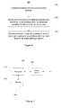
- Figure 6 provides a flowchart illustrating a method 600 for driving one or more light sources, 140, 140'.
- the method 600 comprises observing durations of active periods, wherein an active period corresponds to a continuous period of operating power being supplied to the driver 130, 130', as indicated in block 610.
- the method 600 further comprises selecting one of a plurality of lighting programs for the driver 130, 130' in accordance with the observed durations of one or more active periods, wherein a lighting program defines the desired characteristics of light provided by the respective one or more light sources 140, 140' as a function of time for a subsequent active period, as indicated in block 620.
- the method 600 further comprises controlling, in response to an active period, provision of operating power from the driver 130, 130' to the respective one or more light sources 140, 140' in accordance with the most recently selected lighting program, as indicated in block 630.
- the lighting program selection of block 620 may comprise selecting one of the available lighting programs in accordance with duration of a program setting period, wherein the program setting period is an active period having duration falling below the threshold duration Th p as described in more detail hereinbefore in context of the mode setting portion 134.
- the program setting period may be a portion of an active period, and the duration of the program setting period may be determined by computing the value of the remainder of the duration of a completed active period, e.g. the most recently completed active period, divided by a predetermined divisor, as described in more detail hereinbefore in context of the mode setting portion 134.
- a number of (further) variations to the method 600 may be applied according to the examples described hereinbefore in the context of the monitoring portion 132, to the mode setting portion 134 and to the control portion 136.
- FIG 7 schematically illustrates an exemplifying apparatus 500, e.g. a driver apparatus, that may be employed for embodying the driver 130, 130'.
- the apparatus 500 comprises a processor 510 and a memory 520, the processor 510 being configured to read from and write to the memory 520.
- the apparatus 500 may further comprise further structural units or portions, e.g. ones described hereinbefore in context of Figure 2 with a reference the driver apparatus and a driver portion, represented in Figure 5 as an optional driver portion 530.
- the processor 510 is illustrated as a single component, the processor 510 may be implemented as one or more separate components.
- the memory 520 is illustrated as a single component, the memory 520 may be implemented as one or more separate components, some or all of which may be integrated/removable and/or may provide permanent/semi-permanent/ dynamic/cached storage.
- the memory 520 may comprise the memory 138.
- the apparatus 500 may be embodied as a special-purpose or as a general purpose device with a sufficient processing capacity. Preferably, however, the apparatus 500 is embodied as an apparatus dedicated for operating as the driver 130, 130' or as one or more portions thereof.
- the memory 520 may store a computer program 550 comprising computer-executable instructions that control the operation of the apparatus 500 when loaded into the processor 510 and executed by the processor 510.
- the computer program 550 may include one or more sequences of one or more instructions.
- the computer program 550 may be provided as a computer program code.
- the processor 510 is able to load and execute the computer program 550 by reading the one or more sequences of one or more instructions included therein from the memory 520.
- the one or more sequences of one or more instructions may be configured to, when executed by one or more processors, cause an apparatus, for example the apparatus 500, to implement the operations, procedures and/or functions described hereinbefore in context of the driver 130, 130'.
- the apparatus 500 may comprise at least one processor 510 and at least one memory 520 including computer program code for one or more programs, the at least one memory 520 and the computer program code configured to, with the at least one processor 510, cause the apparatus 500 to perform the operations, procedures and/or functions described hereinbefore in context of the driver 130, 130'.
- the computer program 550 may be provided independently of the apparatus, and the computer program 550 may be provided at the apparatus 500 via any suitable delivery mechanism.
- the delivery mechanism may comprise at least one computer readable non-transitory medium having program code stored thereon, the program code which when executed by an apparatus cause the apparatus at least implement processing to carry out the operations, procedures and/or functions described hereinbefore in context of the driver 130, 130'.
- the delivery mechanism may be for example a computer readable storage medium, a computer program product, a memory device a record medium such as a CD-ROM, a DVD a Blue-ray Disc, a corresponding optical media, an article of manufacture that tangibly embodies the computer program 550, etc.
- the delivery mechanism may be a signal configured to reliably transfer the computer program 550.
- references to a processor should not be understood to encompass only programmable processors, but also dedicated circuits such as field-programmable gate arrays (FPGA), application specific circuits (ASIC), signal processors, etc.
- FPGA field-programmable gate arrays
- ASIC application specific circuits
- Signal processors etc.
Landscapes
- Circuit Arrangement For Electric Light Sources In General (AREA)
Abstract
Description
- The invention relates to control of operation of one or more light sources. In particular, embodiments of the invention relate to a driver that is able to select a lighting program and to control operation of one or more light sources accordingly, as well as to a method and to a computer program for carrying out the selection and control.
- Typically outdoor lighting provided for public places, such as for towns, cities or districts thereof are operated by light sensor based or clock/timer based control systems for switching the lights on or off. Such an arrangement may involve issuing control signals e.g. via dedicated control cables or by employing power-line communication (PLC) techniques to one or more relays in a lightning cabinet, which relays in turn pass the operating power to one or more lights sources accordingly. Such systems typically only allow switching the light sources on or off but do not provide e.g. dimming capabilities.
- Recently, two types of systems that also allow dimming have been provided. Simple ones are capable of dimming down the light sources for a predetermined period(s) of time within a lighting period, which lighting period typically covers the night time. A shortcoming of such systems is that ballasts and/or driver apparatuses employed therein do not offer any flexibility or possibilities for adjusting the dimming characteristics. Consequently, the energy consumption of such a lighting system may be unnecessarily high and/or the provided lighting level cannot be tailored to meet the required characteristics.
- More advanced systems may allow control of lighting by a PLC technique, via a wireless connection or by employing dedicated control cables. While such systems may provide rather versatile possibilities for controlling dimming (and other) behavior of lighting, on the other hand in many cases they provide a level of sophistication greatly exceeding that required for control of lighting of public places and hence incur unnecessarily high costs and possibly also reliability problems.
- Consequently, it is an object of the present invention to provide a technique that is suitable for controlling the lighting of public places and/or other outdoor facilities that provides some flexibility in controlling the intensity and/or other characteristics of the lighting but that is reliable and straightforward to implement without incurring significant changes to the existing infrastructure.
- The objects of the invention are reached by an apparatus, by a method, by a computer program and by an arrangement as defined by the respective independent claims.
- According to an example embodiment, an apparatus for driving one or more light sources is provided. The apparatus comprises a monitoring portion configured to observe durations of active periods, wherein an active period corresponds to a continuous period of operating power being supplied to the apparatus, a mode setting portion configured to select one of a plurality of lighting programs for the apparatus in accordance with the observed durations of one or more active periods, wherein a lighting program defines the desired characteristics of light provided by the one or more light sources as a function of time for a subsequent active period, and a control portion configured to, in response to an active period, control provision of operating power from the apparatus to the one or more light sources in accordance with the most recently selected lighting program.
- According to another example embodiment, a method for driving one or more light sources is provided. The method comprises observing durations of active periods, wherein an active period corresponds to a continuous period of operating power being supplied to a driver apparatus, selecting one of a plurality of lighting programs for the driver apparatus in accordance with the observed durations of one or more active periods, wherein a lighting program defines the desired characteristics of light provided by the one or more light sources as a function of time for a subsequent active period, and controlling, in response to an active period, provision of operating power from the driver apparatus to the one or more light sources in accordance with the most recently selected lighting program.
- According to another example embodiment, a computer program for driving a light source is provided. The computer program comprises one or more sequences of one or more instructions which, when executed by one or more processors, cause an apparatus at least to observe durations of active periods, wherein an active period corresponds to a continuous period of operating power being supplied to the driver apparatus, to select one of a plurality of lighting programs for the driver apparatus in accordance with the observed durations of one or more active periods, wherein a lighting program defines the desired characteristics of light provided by the one or more light sources as a function of time for a subsequent active period and to control, in response to an active period, provision of operating power from the driver apparatus to the one or more light sources in accordance with the most recently selected lighting program.
- The computer program may be embodied on a volatile or a non-volatile computer-readable record medium, for example as a computer program product comprising at least one computer readable non-transitory medium having program code stored thereon, the program code, which when executed by an apparatus, causes the apparatus at least to perform the operations described hereinbefore for the computer program in accordance with an example embodiment.
- The exemplifying embodiments of the invention presented in this patent application are not to be interpreted to pose limitations to the applicability of the appended claims. The verb "to comprise" and its derivatives are used in this patent application as an open limitation that does not exclude the existence of also unrecited features. The features described hereinafter are mutually freely combinable unless explicitly stated otherwise.
- The novel features which are considered as characteristic of the invention are set forth in particular in the appended claims. The invention itself, however, both as to its construction and its method of operation, together with additional objects and advantages thereof, will be best understood from the following detailed description of specific embodiments when read in connection with the accompanying drawings.
-
-
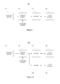
Figure 1 a schematically illustrates an exemplifying arrangement in accordance with an example embodiment. -
Figure 1b schematically illustrates an exemplifying arrangement in accordance with an example embodiment. -
Figure 2 schematically illustrates a driver in accordance with an example embodiment. -
Figure 3 illustrates exemplifying lighting programs in accordance with an example embodiment. -
Figure 4 illustrates an example of selecting lighting programs in accordance with an example embodiment. -
Figure 5 illustrates an example of selecting lighting programs in accordance with an example embodiment. -
Figure 6 illustrates a method in accordance with an embodiment of the present invention. -
Figure 7 schematically illustrates an apparatus in accordance with an example embodiment. -
-
Figure 1 a schematically illustrates anexemplifying arrangement 100 suitable for example for providing and controlling outdoor lighting of public places, such as parks, streets, residential areas, districts of towns or cities or even towns or cities in their entirety. Equally well thearrangement 100 can be employed for providing and controlling outdoor lighting for private properties, such as shopping malls, office buildings, apartment buildings, private houses and their surroundings. Thearrangement 100 comprises acontrol entity 110 for controlling the power supply to thelight sources 140, aswitching entity 120 for controlling the supply of operating power to thedriver 130 in accordance with control signal(s) received from thecontrol entity 110, adriver 130 for controlling operation of alight source 140 coupled thereto on basis of the operating power received via theswitching entity 120. -
Figure 1b schematically illustrates another exemplifying arrangement 100' as a variation of thearrangement 100, the arrangement 100' involving a second driver 130' for controlling operation of a light source 140' coupled thereto on basis of the operating power received via theswitching entity 120.Separate drivers 130, 130', typically of different characteristics, may be useful e.g. to control operation oflight sources 140, 140' of different types and/or to control operation oflight sources 140, 140' of otherwise different characteristics or having different requirements with respect to operating power supplied thereto. - Although the
arrangements 100, 100' are depicted with eachdriver 130, 130' controlling a singlerespective light source 140, 140', each of thedrivers 130, 130' may be arranged to control one or morerespective light sources 140, 140'. Along similar lines, instead of controlling power supply to one or twodrivers 130, 130', the switchingentity 120 generalizes into one arranged to control power supply to one ormore drivers 130, 130', each arranged to control respective one ormore light sources 140, 140'. Furthermore, thecontrol entity 110 may be arranged to control the power supply to thelight sources 140, 140' by controlling one or more switchingentities 120, each switching entity arranged to control power supply to respective one ormore drivers 130, 130' and each of the one ormore drivers 130, 130' arranged to control respective one ormore light sources 140, 140'. - The
control entity 110 may comprise for example one or more user-operable switches that can be employed to manually control issuing one or more controls signals to the switchingentity 120, consequently resulting in the switchingentity 120 to supply operating power to the one ormore drivers 130, 130' in order to thedrivers 130, 130' to switch the operating power to the respective one ormore light sources 140, 140', i.e. to turn the lights on or off. The one or more control signals may be provided to the switchingentity 120 e.g. via dedicated control cables or by employing a PLC technique. As a further example, the one or more control signals may be provided to the switching entity over a wireless link, e.g. one based on a cellular communication technique such as GSM. - As another example, alternatively or additionally, the
control entity 110 may comprise an automated control arrangement comprising one or more light sensors arranged to issue the one or more control signals that cause turning the lights on and/or off in accordance with the observed level of ambient light. As a further example, alternatively or additionally, such an automated control arrangement may comprise one or more timers that may be arranged to issue the one or more control signals that cause turning the lights on and/or off according to a predetermined rule, e.g. in order to provide lighting for a period of desired duration starting at a desired point of time. Typically, a sensor arrangement or a timer arrangement aims to automatically control the lights to be turned on for the time of the day when there is little or no daylight available. Thecontrol entity 110 may be arranged to employ a combination of control means, e.g. a combination of the user-operable switch, one or more light sensor and/or one or more timers, for example such that after manually controlling to switch the lights on, the lights will be turned off after a desired period of time and/or in response to observed level of ambient light exceeding a predetermined threshold level. As another example in this regard, the one or more control signals causing the lights to be switched on may be issued in response to observed level of ambient light falling below a predetermined threshold and subsequently one or more control signals causing the lights to be switched off are issued after a predetermined period of time. - As pointed out hereinbefore, the
control entity 110 may be arranged to issue the one or more control signals toseveral switching entities 120. Such an arrangement may be useful e.g. in relative large scale lighting systems or arrangements covering a plurality of public places such as parks, streets, districts of towns/cities etc. In smaller scale lighting systems or arrangements, such as apartment buildings and private houses, thecontrol entity 110 may be omitted an a user may directly operate the switchingentity 120 e.g. via a user-operable switch or a corresponding arrangement provided in theswitching entity 120. - The switching
entity 120 may comprise for example one or more relays, each relay arranged to control supply of operating power to one ormore drivers 130, 130' coupled thereto. The operating power is obtained from an external power supply or power source, typically from mains electricity. - The
driver 130, 130' is preferably capable of adjusting the characteristics of light provided by the respective one ormore light sources 140, 140' it is arranged control. The adjustment of characteristics may comprise, for example, adjustment of the light intensity, the adjustment of color of light and/or the adjustment of the color temperature of light provided by the respective one ormore light sources 140, 140'. The adjustment may be provided e.g. on basis of one or more control signals received from the switchingentity 120. Thedriver 130, 130' may be for example a light emitting diode (LED) driver and, consequently, the respective one ormore light sources 140, 140' thedriver 130, 130' is arranged to control comprise LED light sources. As another example, thedriver 130, 130' may comprise a driver for a high-intensity discharge (HID) lamp, such as a sodium vapor lamp or a mercury vapor lamp and, consequently, the one respective one ormore light sources 140, 140' are HID lamps of a corresponding type. Generally speaking, anylight sources 140, 140' or any combination oflight sources 140, 140' that enable adjustment of light characteristics thereof may be employed together with adriver 130, 130' of respective type. - In case the
driver 130, 130' is arranged to control operation of respective two or morelight sources 140, 140', the two or morelight sources 140, 140' may be arranged into one or more luminaires. Consequently, thedriver 130, 130' may be configured to control light sources of one or more luminaires. -
Figure 2 schematically illustrates thedriver 130, 130'. Thedriver 130, 130' comprises amonitoring portion 132 for observing durations of periods of operating power being supplied to thedriver 130, 130', amode setting portion 134 for adjusting the operation of thedriver 130, 130' and acontrol portion 136 for controlling the operation of the one or morelight sources 140. Thedriver 130, 130' may further comprise amemory 138 or thedriver 130, 130' may otherwise have access to a memory, either in the driver apparatus or in another entity connected or coupled to thedriver 130, 130'. One or more of themonitoring portion 132, themode setting portion 134 and thecontrol portion 136 may be configured to read from and/or to write to the memory 138 (or to/from a memory accessible by thedriver 130 but provided outside thedriver 130, 130'). - The
driver 130, 130' may be provided e.g. in a driver apparatus. Thedriver 130, 130' and/or the driver apparatus is provided with means for receiving the operating power and means for providing operating power to the one or morelight sources 140, 140'. Consequently, the driver apparatus may be provided with an arrangement for connecting or coupling the one or morelight sources 140, 140' to thedriver 130, 130'. Thedriver 130, 130' or the driver apparatus typically comprises further portions, for example a power converter for converting an operating power supplied to thedriver 130, 130' or to the driver apparatus to exhibit characteristics suitable for driving the operation of the one or morelight sources 130, 130'. As another example, thedriver 130, 130' may further comprise feedback circuitry arranged to monitor electric current supplied to the one or morelight sources 140, 140' in order to facilitate driving the power converter in a desired manner. In context of the present invention such general driver functionality that is well known in the art may be conceptually provided e.g. in a driver portion of thedriver 130, 130' or the driver apparatus. - The
monitoring portion 132 may be configured to observe durations of continuous periods of operating power being supplied to thedriver 130, 130' or to the driver apparatus. A single period of operating power being continuously supplied to thedriver 130, 130' may be referred to as an active period. Hence, the monitoring portion may be configured to observe durations and/or timing of active periods and store information regarding the observations to a memory, e.g. thememory 138, for subsequent use by themode setting portion 134. The information regarding a given observed active period may comprise, for example, one or more of the following: information indicating the duration of the given active period, information indicating starting time of the given active period, information indicating ending time of the given active period, information indicating the time between the beginning of the given active period and the end of the active period (immediately) preceding the given active period. Themonitoring portion 132 may be configured to keep information regarding a predetermined number of most recent active periods. As another example, themonitoring portion 132 may be configured to keep information regarding active periods that have occurred within a predetermined period of time, e.g. within a predetermined period of time from the current time. - The
monitoring portion 132 may be further configured to observe durations and/or timing of non-active periods, i.e. continuous periods of operating power not being supplied to thedriver 130, 130' or to the driver apparatus, and store information regarding the observations to a memory, e.g. thememory 136, for subsequent use by themode setting portion 134. Like in case of the active periods, themonitoring portion 132 may be configured to keep information regarding a predetermined number of most recent non-active periods or information regarding the non-active periods covering a predetermined time window. Instead of themonitoring portion 132 actively keeping track of the non-active periods, the information indicative of the durations and/or timing of non-active periods may be derivable from the information regarding the observed active periods. - As described hereinbefore, basically an active period is a continuous period of operating power being supplied to the
driver 130, 130' or to the driver apparatus, typically via theswitching element 120 in control of thecontrol element 110. However, themonitoring portion 132 may be configured to ignore short interruptions in operating power supplied to thedriver 130, 130' in order to avoid short-term disturbances and/or other unintentional short-term failures to provide operating power to disturb monitoring and evaluation of durations of active periods. As an example, themonitoring portion 132 may be configured to ignore interruptions in received operating power that are shorter than or equal to a threshold duration Th I, where the value of the threshold duration Th I may be selected e.g. from the range from 1 to 5 seconds. In other words, themonitoring portion 132 may be configured to consider an active period to be completed only in response to a non-active period that is longer than the threshold duration Th I . - Alternatively, the
monitoring portion 132 may be configured to consider a non-active period that is shorter than the threshold Th l as an indication of an error condition in the system and, consequently, themode setting portion 134 may be configured to resort to a default lighting program (as described hereinafter) in response to a non-active period having duration that does not exceed the threshold Th l . - The
mode setting portion 134 is configured to select one of a plurality of lighting programs for thedriver 130 in accordance with the observed durations of one or more active periods. The lighting program is selected for one or more subsequent active periods. In other words, the observed durations of the active periods serve as control signal(s) arranged to control the manner of thedriver 130, 130' adjusting the characteristics of light to be provided by the one or morelight sources 140 during one or more subsequent active periods, thereby dispensing with the need to provide dedicated control cables or a wireless arrangement for providing the control signal(s) hence enabling a reliable and cost-efficient solution in this regard. - The
mode setting portion 134 may be configured to pass the information indicating the selected lighting program directly to thecontrol portion 136. Alternatively or additionally, themode setting portion 134 may be configured to store the information indicating the selected lighting program in a memory, e.g. in thememory 138 for subsequent use by thecontrol portion 138. Themode setting portion 134 may be further configured to keep information regarding a predetermined number of most recently selected lighting programs or to keep information regarding the selected lighting programs during a time window of predetermined duration. Such history information regarding the selected lighting programs may be subsequently employed e.g. by themode setting portion 134 as part of future lighting program selection decisions. The information indicating the selected lighting program may be provided and/or stored together with information indicating the time of the respective selection having been made. - The
control portion 136 is configured to control the operation of the respective one or morelight sources 140, 140' in accordance with the most recently selected lighting program. As an example in this regard, thecontrol portion 136 may be configured to drive the respective one or morelight sources 140, 140' to provide light intensity according to the information defining the desired light intensity profile as a function of time in response to operating power being supplied to thedriver 130, 130', i.e. in response to an active period. In this regard, driving the one or morelight sources 140, 140' may comprise controlling provision or supply of the operating power received at thedriver 130, 130' to the respective one or morelight sources 140, 140' resulting in the respective desired light intensity. - As an example, in case of a LED light source predetermined electric current is typically required to cause the LED light source to provide its maximum (i.e. 100 %) light intensity. Instantaneous light intensity provided by the LED light source is typically directly proportional to the electric current supplied thereto, and hence providing a desired percentage of the predetermined electric current to a LED light source serves to control the LED light source to provide a corresponding percentage of its maximum light intensity. As another example, a LED light source may be controlled by supplying the predetermined electric current required to cause the LED light source to provide its maximum light intensity intermittently, such that the periods of time during which the electric current is supplied to the LED constitute a desired percentage of time. Consequently, if the periods of time during which the electric current is supplied to the LED light source are sufficiently short, this results in the perceived light intensity from the LED light source to exhibit the corresponding percentage of its maximum light intensity. Typically, periodic switching at 200 Hz or above is applied to ensure that a human vision does not perceive the on/off switching of the LED light source as flickering of light.
- A lighting program defines desired characteristics of light to be provided by the respective one or more
light sources 140, 140' as a function of time. Hence, a lighting program may be also referred to e.g. as an operating mode, an operating profile or a lighting profile defining the desired temporal variations in characteristics of the light to be provided by the respective one or morelight sources 140, 140'. Information defining the characteristics of light according to a lighting program may be stored, for each of the plurality of lighting programs, to a memory, e.g. to thememory 138. Preferably, the plurality of lighting programs is pre-stored in thedriver 130, 130'. - Without losing generality, a lighting program may be divided into one or more segments, and information defining the characteristics of a lighting program may be arranged into information units or information elements, each of which defining desired characteristics of light determined for the corresponding segment of the lighting program. Each information unit/element, and hence the corresponding segment, is preferably also provided with timing information defining the duration of the segment and the timing of the segment with respect to a common reference point and/or with respect to one or more other segments of the lighting program. The common reference point may be e.g. the beginning of the light program or the end of the light program, and the timing information may comprise information that defines the starting time and/or the ending time of the segment with respect to the reference point. Instead of or in addition to applying a common reference point, the starting and/or ending time(s) of a given segment may be defined with respect to the starting/ending time of another segment of the lighting program, e.g. the segment immediately preceding or the segment immediately following the given segment.
- The information defining the characteristics of light for a lighting program may comprise information defining the desired light intensity to be provided by the one or more
light sources 140 as a function of time. Such information may be provided e.g. a series of light intensity values, e.g. in range from 0 to 100 % of the maximum light intensity of the respectivelight sources 140, each value defining the desired light intensity for the respective time period, the series of the light intensity values covering the desired duration of the lighting program. Hence, a light intensity value may be considered as the information unit/entity defining the lighting characteristics for the corresponding segment of the lighting program. - As another example, the information defining the desired light intensity information for a lighting program may be provided as a series of value pairs, where a first value of a pair defines the desired light intensity, e.g. in range from 0 to 100 % of the maximum light intensity of the respective
light sources 140 while a second value of the pair defines fraction of the total duration of the lighting program for which the light intensity according to the first value of the pair is to be provided, thereby defining a relative duration of the light intensity to be provided in accordance with the first value of the pair. The value pairs may be provided as an ordered series, thereby providing the information units/elements constituting the lighting program. Alternatively or additionally, each value pair may be further provided with timing information as described hereinbefore, e.g. with timing information that defines the starting time of the segment of the lighting program corresponding to the respective segment with respect to the beginning of the lighting program or with respect to the end of the lighting program. As an example in this regard, a lighting program may define e.g. to keep the lights on at maximum light intensity for a segment covering the first 40 % of the overall duration of the lighting program, to keep the lights on at 80 % of the maximum light intensity for a segment covering the last 25 % of the overall duration of the lighting program and to keep the lights off during the remaining segment between these two segments covering the remaining 35 % of the overall duration of the lighting program. - As a variation of the previous example, instead of defining desired static light intensity, a value pair may define a transition from first light intensity level to a second light intensity level during the period defined for the value pair. The transition may be defined as a linear transition or a transition to be carried out using another predetermined pattern.
- The examples regarding the information that may be applied to define a lighting program described hereinbefore apply the intensity of light as an example of the characteristics of light that may be defined by the lighting program. However, the examples are applicable for representing information defining other characteristics of light in addition to or instead of light intensity, e.g. color of light and/or color temperature of light to be provided by one or more
light sources 140. - Some examples of lighting programs that define desired light intensity characteristics as a function of time are provided in
Figure 3 . The lighting programs a) through g) illustrated inFigure 3 serve as non-limiting examples of lighting programs that define the desired relative light intensity as a function of time, as indicated by the respective bold lines. InFigure3 t 0 denotes the starting time of a lighting program and t end denotes the end of a lighting program. - The lighting program a) defines the maximum light intensity (100 %) to be provided throughout the lighting program. This lighting program may be considered to comprise a single segment providing 100 % light intensity throughout the lighting program.
- The lighting program b) defines 100 % light intensity to be provided from the beginning of the lighting program until time t b1 (a first segment), half of the maximum light intensity (50 %) to be provided from time t b1 until time t b2 (a second segment) and 100 % light intensity to be provided from time t b2 until the end of the lighting program (a third segment).
- The lighting program c) defines 50 % light intensity to be provided from the beginning of the lighting program until time t c (a first segment) and 80 % of the maximum light intensity to be provided from time t c until the end of the lighting program (a second segment).
- The lighting program d) defines 100 % light intensity to be provided from the beginning of the lighting program until time t d (a first segment)and 50 % light intensity to be provided from time t d until the end of the lighting program (a second segment).
- The lighting program e) defines 100 % light intensity to be provided from the beginning of the lighting program until time t e1 (a first segment), the light intensity to be gradually dimmed from 100 % light intensity to the 0 % light intensity (i.e. switching the lights off) during the period from time t e1 to time t e2 (a second segment), the lights to be kept off from time t e2 until time t e3 (a third segment) and 80 % light intensity to be provided from time t e3 until the end of the lighting program (a fourth segment).
- The lighting program f) defines 100 % light intensity to be provided from the beginning of the lighting program until time t f1 (a first segment), the light intensity to be gradually dimmed from 100 % light intensity to the 0 % light intensity (i.e. switching the lights off) during the period from time t f1 to time t f2 (a second segment) and the lights to be kept off from time t f2 until the end of the lighting program (a third segment).
- As described hereinbefore, the time instants referred to in the example lighting programs a) to f) may be defined e.g. as absolute time since the beginning or the program or as absolute time before the end of the lighting program. Hence, for example the time instant t b1 may be defined to occur e.g. at "t b1 hours/minutes/seconds since the beginning of the lighting program" and the time instant t b2 may be defined to occur e.g. at "t b2 hours/minutes/seconds before the end of the lighting program. As another example, the time instant t c may be defined to occur e.g. at "t c hours/minutes/seconds since the beginning of the lighting program" or at "t c hours/minutes/seconds before the end of the lighting program".
- Alternatively, as also described hereinbefore, the time instants may be defined in relation to the total duration of the lighting program. As an example in this regard, the time instant t b1 may be defined to occur e.g. at "25 % of the total duration of the lighting program since the beginning of the lighting program" and the time instant t b2 may be defined to occur at "15 % of the total duration of the lighting program before the end of the lighting program". As another example, the time instant t c may be defined to occur e.g. at "32 % of the total duration of the lighting program since the beginning of the lighting program" or at "68 % of the total duration of the lighting program before the end of the lighting program".
- Basically the
control portion 136 is configured to terminate the lighting program it is currently applying in response to completion the active period that triggered initiation of the lighting program. A lighting program may be provided with information defining its duration, possibly stored together with the other information defining the lighting program in a memory, e.g. in thememory 138. A lighting program may be further provided with information defining the action to be taken upon reaching the end of the lighting program indicated by the duration thereof. A few examples in this regard are described in the following. - A lighting program may be defined, for example, as a lighting program that has a predetermined default duration that can be changed, as will be described by examples in more detail hereinafter. Hence, a lighting program may have an adjustable or programmable duration. As a further example, a lighting program may be defined as an open-ended lighting program that defines the lighting characteristics at the end of the lighting program to be continued until completion of the active period that triggered initiation of the lighting program or until receiving an explicit control signal or other indication terminating the lighting program. Consequently, the
control portion 136 may be configured to continue driving the respective one or morelight sources 140, 140' using the lighting characteristics applied at the end of the lighting program until instructed otherwise. - In case a lighting program has no explicit duration defined therefor, the
control portion 136 may be configured to determine an estimated duration of the lighting program on basis of one or more completed active periods. The estimated duration may be defined e.g. as the duration of the most recently completed active period or as an average of the durations of a predetermined number of most recently completed active periods. The determination of the estimated duration may consider all completed active periods or the determination may consider only completed active periods that have duration exceeding a predetermined threshold duration. - The
control portion 136 may be configured to use the predefined or estimated duration of a lighting program in order to determine time instants that are defined with respect to the beginning of the lighting program, e.g. a starting time and/or an ending time for one or more segments of the lighting program defined to cover predetermined percentages of the total duration of the lighting program. - Along similar lines, the
control portion 136 may be configured to use the predefined or estimated duration of a lighting program to determine time instants that are defined with respect to the end of the lighting program, e.g. a starting time or an ending time of a segment of the lighting program at predetermined number of hours/minutes/seconds before the end of the lighting program, a starting time and/or an ending time for one or more segments of the lighting program defined to cover predetermined percentages of the total duration of the lighting program, e.g. a starting time for a segment covering a predetermined percentage of the total duration of the lighting program at the end of the lighting program. - Alternatively or additionally, the
control portion 136 may be configured apply the estimated duration for terminating a lighting program that has no predefined duration assigned therefor: thecontrol portion 136 may be configured to terminate the lighting program in response to the estimated duration after commencing the lighting program having elapsed. - The
driver 130, 130' may be provided with a default lighting program. The default lighting program may be employed e.g. as an initial lighting program that is to be applied by thecontrol portion 136 before the first selection of a lighting program has been carried out by themode setting portion 134. The default lighting program may also be the lighting program to be applied (e.g. selected) in case of a malfunction of thedriver 130, 130' or in case there is any confusion or uncertainty about the correct lighting program. The default lighting program is preferably a lighting program that provides lighting characteristics that ensure sufficient level of lighting in all operating conditions. The default lighting program may be a special-purpose lighting program that cannot be selected on basis of the observed duration of the active period(s) or the default lighting program may be one of the plurality of lighting programs from which the lighting program to be applied is selected in accordance with the observed durations of active period(s). As an example, the lighting program a) illustrated inFigure 3 is a lighting program suitable as the default lighting program. - The
control portion 136 may be configured terminate the currently applied lighting program in response to the duration of the currently applied lighting program having exceeded the defined or estimated duration of the lighting program by at least a predetermined margin. Such a margin may be defined as an absolute time, e.g. as a suitable value in the range from 30 min to 2 hours, or as a percentage of the defined/estimated duration, e.g. as a suitable percentage in the range from 5 % to 25 %. Thecontrol portion 136 may be further configured to, immediately after termination of the lighting program, to control switching the lights to the maximum light intensity or to commence execution of the default lighting program. - The
control portion 136 may be configured to terminate application of the currently selected lighting program and to start applying the default lighting program in response to a predetermined sequence of active periods. Such predetermined sequence is preferably defined such that it is extremely unlikely to occur in normal operating conditions. As an example, such a sequence may comprise a predetermined number of short interruptions in power supply during an active period with a fixed time period in-between, e.g. three interruptions of less than one second with a period of 3 seconds therebetween. - The
mode setting portion 134 may be configured to select the lighting program among the plurality of lighting programs in accordance with duration of a single active period. In particular, themode setting portion 134 may be configured to interpret an active period having duration that is shorter than a threshold duration Th p as a control signal intended to indicate the desired lighting program for thedriver 130, 130'. In other words, the active period having duration not exceeding the threshold duration Th p may serve as a program setting period. Alternatively, instead of merely considering an upper limit of duration, i.e. the threshold duration Th p, themode setting portion 134 may consider an active period having duration in the range from Th p0 to Th p as a program setting period. The value of the threshold Th p0 may be e.g. in the range 2 to 10 seconds and the value of the threshold Th p may be e.g. in the range from 20 to 120 seconds, depending e.g. on the number of available lighting programs. However, these values serve as non-limiting examples and threshold values outside the exemplifying ranges may be applied. - Once the program setting period is completed and the
mode setting portion 134 has selected the lighting program accordingly, the control portion may be configured to apply the selected lighting program in response to a subsequent active period, e.g. the active period immediately following the program setting period and/or to any active period following the most recent program setting period until detecting a subsequent program setting period. - Preferably, the
control portion 136 is configured to refrain from providing operating power to the respective one or morelight sources 140, 140' in response to an active period not exceeding the threshold duration Th p, thereby avoiding unnecessarily turning on the lights for a short period of time in response to a period of operating power supplied to thedriver 130, 130' with the purpose of selecting the desired lighting program for a subsequent active period exceeding another threshold duration Th L In other words, thecontrol portion 136 may be configured to provide operating power to the respective one or morelight sources 140, 140' only in response to an active period having duration that exceeds the threshold duration Th L. Such active period exceeding the threshold duration Th L is hence treated as a lighting period. The threshold duration Th L is longer than or equal to the threshold duration Th p. Consequently, the value selected for the threshold Th L depends on the value of the threshold Thp, and may be e.g. set to a value Th L = Th p + T margin, where the value of T margin may be selected e.g. from the range from 0 to 10 seconds. - The threshold duration Th L may be further applied as the predetermined duration serving as the lower limit for duration of a completed active period considered in determination of the estimated duration of a lighting program, as described hereinbefore.
- Alternatively, the
control portion 136 may be configured to provide operating power to the respective one or morelight sources 140, 140' according to the most recently selected lighting program in response to any active period regardless of its duration. Hence, in this scenario each active period is considered as a lighting period, whereas a short active period falling short of the threshold duration Th p is additionally considered as a program setting period. While this approach contributes towards avoiding unnecessary delays in switching on the lights in response to supplying operating power to thedriver 130. 130', it may result in unnecessary blinking of lights in case the active period is primarily provided as a program setting period that is terminated before its duration reaching the threshold duration Th p. - The
mode setting portion 136 may be configured to select the lighting program for a subsequent lighting period on basis of the duration of the program setting period, i.e. on basis of the duration of a single active period having duration that does not exceed the threshold duration Th p. In this regard, the timeline below the threshold duration Th p may be divided into two or more sub-ranges, where each sub-rage is associated with a single lighting program of the plurality of lighting programs. The sub-ranges are non-overlapping, and they are preferably defined as adjacent sub-ranges such that an upper limit of a given sub-range equals to the lower limit of the next higher sub-range. - An example of sub-ranges is provided in the first column of Table 1 with the second column of Table 1 indicating the lighting program (with reference to the lighting programs a) to f) of the example provided in
Figure 3 ) associated with the respective sub-range.Table 1 Program setting period Lighting program < 10 seconds Program a) 10 - 20 seconds Program b) 20 - 30 seconds Program c) 30 - 40 seconds Program d) 40 - 50 seconds Program e) 50 - 60 seconds Program f) - The
mode setting portion 134 may be configured to determine the sub-range within which the duration of the program setting period falls and to select the lighting program associated with the sub-range so determined. Hence, in the example of Table 1 themode setting portion 134 is configured to select, in response to an active period that is shorter than or equal to 60 seconds one of the lighting programs a) to f) in accordance with the duration of the active period. Consequently, thecontrol portion 136 applies the selected lighting program in response a subsequent lighting period. - In a variation of the example described in context of Table 1, the sub-ranges are not defined as adjacent sub-ranges but a gap between two consecutive sub-ranges is provided. An example of sub-ranges of such type is provided in Table 2.
Table 2 Program setting period Lighting program 5 - 10 seconds Program a) 15 - 20 seconds Program b) 25 - 30 seconds Program c) 35 - 40 seconds Program d) 45 - 50 seconds Program e) 55 - 60 seconds Program f) - Hence, in the example of Table 2 the
mode setting portion 134 is configured to select, in response to an active period that is shorter than or equal to 60 seconds one of the lighting programs a) to f) in accordance with the duration of the active period provided that the duration of the active period falls within one of the ranges defined in Table 2. - In case the duration of the active period that is shorter than 60 seconds falls outside the sub-ranges of Table 2, the program selection may be considered as undefined and the most recently selected mode is to be applied for a subsequent lighting period. Alternatively, the
mode selection portion 134 may be configured to change to the default lighting program in response to the duration of the active period falling within one of the undefined sub-ranges. Such active periods that are shorter than 60 seconds but fall outside the sub-ranges of Table 2 may be employed e.g. to issue mode selection commands to other drivers without affecting the operation or mode selection of thedriver 130, 130'. As an example in this regard, e.g. in the exemplifying arrangement 100', or in any arrangement where asingle switching entity 120 is feeding two ormore drivers 130, 130', the driver 130 (or themode selection portion 134 thereof) may be configured to select the lighting program in accordance with Table 2, whereas the driver 130' (or themode selection portion 134 thereof) may be configured to select the lighting program in accordance with Table 3.Table 3 Program setting period Lighting program < 5 seconds Program a) 10 - 15 seconds Program b) 20 - 25 seconds Program c) 30 - 35 seconds Program d) 40 - 45 seconds Program e) 50 - 55 seconds Program f) - While typically the plurality of lighting programs are defined as static lighting programs that cannot be changed, modified or adjusted once provided to the
driver 130, 130', themode setting portion 134 may be configured to modify or adjust at least one characteristics of one or more of the plurality of lighting programs in accordance with a control signal. As an example, such a control signal may comprise one or more active periods following a program setting period, referred to in the following as program adjustment period(s). Themode setting portion 134 may be configured to modify at least one characteristics or parameter of one or more of the plurality of lighting programs in accordance with durations of the one or more program adjustment period. Hence, the modification of a lighting program may be triggered by reception of two or more (consecutive) active periods in accordance with durations thereof, the first one causing themode setting portion 134 to set thedriver 130, 130' into a program adjustment mode of operation and the second and possible further ones determining the characteristics and scope of the program adjustment to be applied. - As an example in this regard, one or more predetermined sub-ranges of the mode setting period may be associated with a program adjustment mode of operation while the other sub-ranges may be associated with the lighting programs from a) to f), along the lines described in context of Table 1. A concrete example for such a scenario is provided in Table 4 that may be applied to extend e.g. Table 1, Table 2 or Table 3.
- Hence, in the example of Table 4 the
mode setting portion 134 is configured to select, in response to an active period that is shorter than or equal to 200 seconds, either one of the lighting programs a) to f) in accordance with the duration of the active period provided that the duration of the active period falls within one of the ranges defined in Table 1, Table 2 or Table 3 or one of the program adjustment modes in case the duration of the active period interpreted as the program setting period has a duration that falls within one of the sub-ranges defined in Table 4 covering the durations from 60 to 240 seconds. In case the duration of the active period indicates selection of one of the lighting programs, the operation continues with thecontrol portion 136 applying the selected lighting program in response to a subsequent lighting period. In case the duration of the active period indicates entry into one of the program adjustment modes, one or more active periods to be interpreted as program adjustment periods will follow, and themode setting portion 134 is configured to adjust characteristics of at least one of the plurality of lighting programs in accordance with the durations of the one or more program adjustment period.Table 4 Program setting period Adjustment operation 60 - 70 seconds Next command will give new max light level for all lighting programs 70 - 80 seconds Next command will give new min light level for all lighting programs 80 - 90 seconds Adjust light levels of lighting program a) 90 - 100 seconds Adjust light levels of lighting program b) 100 - 110 seconds Adjust light levels of lighting program c) 110 - 120 seconds Adjust light levels of lighting program d) 120 - 130 seconds Adjust light levels of lighting program e) 130 - 140 seconds Adjust light levels of lighting program f) 140 - 150 seconds Reprogram segment durations of lighting program a) 150 - 160 seconds Reprogram segment durations of lighting program b) 160 - 170 seconds Reprogram segment durations of lighting program c) 170 - 180 seconds Reprogram segment durations of lighting program d) 180 - 190 seconds Reprogram segment durations of lighting program e) 190 - 200 seconds Reprogram segment durations of lighting program f) - New light levels and/or segment durations for the lighting programs selected for adjustment or reprogramming are determined in accordance with durations of the subsequent one or more active period(s), e.g. as defined by an example in Table 5.
Table 5 Program adjustment period Selection for intensity or duration < 5 seconds 0% 5 - 10 seconds 10% 10 - 15 seconds 20% 15 - 20 seconds 30% 20 - 25 seconds 40% 25 - 30 seconds 50% 30 - 35 seconds 60% 35 - 40 seconds 70% 40 - 45 seconds 80% 45 - 50 seconds 90% 50 - 55 seconds 100% - Hence, the duration of a given program adjustment period may be used to indicate a desired reprogrammed/adjusted light intensity (as a percentage of the maximum light intensity) or the duration (as a percentage of the overall duration of the lighting program). A few examples of possible program adjustment periods that may be associated with the exemplifying programming approaches listed in Table 4 are provided in the following.
- The first two examples of Table 4 affect all lighting programs and hence duration of a single program adjustment period is used to indicate the new maximum or minimum light intensity level for all lighting programs e.g. in accordance with Table 5.
- The third to eighth examples of Table 4 affect light levels of segments of the respective lighting programs. Consequently, the number of program adjustment periods that follow the program setting period causing entry to the program adjustment mode of operation is the same as the number of segments in the respective lighting program, with duration of each program adjustment period defining the reprogrammed light intensity for the respective segment of the lighting program under adjustment.
- The ninth to fifteenth examples of Table 4 affect durations of segments of the respective lighting programs. Consequently, the number of program adjustment periods that follow the program setting period causing entry to the program adjustment mode of operation is the same as the number of segments in the respective lighting program, with duration of each program adjustment period defining the reprogrammed duration for the respective segment of the lighting program under reprogramming.
- This way, light levels and/or durations of lighting program segments may be practically freely adjusted e.g. to provide a fit with changing operating conditions e.g. due to changes in the amount of daylight changing over the year or to otherwise adjust/reprogram the lighting programs to provide different behavior. As an example in this regard, for summer time the maximum light output can be set to 70 % to save energy, while for the winter time the maximum output can be set (back) to 100 % to ensure sufficient illumination. If the reprogrammed durations of segments of a lighting program do not sum up to 100% they can be automatically adjusted so that they do, preferably by preserving the relationship between the reprogrammed segment durations.
- The
mode setting portion 134 may be configured to adjust the selected lighting program or all lighting programs by modifying the information defining the characteristics of the respective lighting program(s) stored in a memory, e.g. in thememory 138, accordingly. Themode setting portion 134 may be configured to keep a copy of the original information defining the characteristics of the lighting programs and apply all possible modifications to working copies thereof to ensure that the original lighting programs may be restored by resetting thedriver 130, 130' e.g. in case of a malfunction or error state of thedriver 130, 130'. - For example in the exemplifying arrangement 100', or in any arrangement where a
single switching entity 120 is applied to feed operating power to two ormore drivers 130, 130', bothdrivers 130, 130' may be configured to select the lighting program in response to the same program selection period. As an example, thedriver 130 and the driver 130' may both apply similar selection rule, e.g. the one exemplified in Table 1, Table 2 or Table 3. Alternatively, thedriver 130 and the driver 130' (and possible further drivers) may be configured to apply different selection rules in response to the same program selection period. As an example in this regard, the selection rule may result in selection of a different lighting program from the same or similar set of plurality of lighting programs at thedriver 130 and the driver 130' in response to the same program setting period. As another example, some or all of the lighting programs available at thedriver 130 may be different from those available at the driver 130'. Such arrangements may enable e.g. employing asingle control entity 110 and/or asingle switching entity 120 to control lighting for environments of different lighting requirements. - The
mode setting portion 136 may be configured to select the lighting program for a subsequent lighting period on basis of the duration of the preceding lighting period, hence without a need to apply or issue dedicated program setting periods. Such an approach may be beneficial e.g. in an arrangement where asingle switching element 120 is employed to control supply of operating power both todrivers 130, 130' that are capable of applying one of a plurality lighting programs and to legacy drivers that are not at all capable of selecting lighting programs or drivers that apply other techniques for selecting a lighting program. This may be especially beneficial in scenarios where thesame switching element 120 is supplying operating power both to one ormore drivers 130, 130' and to a legacy driver that is driving e.g. one or more HID lamps, such as sodium vapor lamps or mercury vapor lamps, that are likely to suffer from short active periods of operating power supplied thereto. - Hence, as an alternative to applying a dedicated program setting period not exceeding the threshold duration Thp, the
mode setting portion 134 may be configured to select the lighting program among the plurality of lighting programs in accordance with duration of the most recent lighting period. Thus, in this scenario the lighting period - or a portion thereof - simultaneously serves as the program setting period. As an example in this regard, themode setting portion 134 may be configured to apply a predetermined divisor and to determine or compute the remainder of the duration of a preceding completed active period divided by the predetermined divisor. The preceding completed active period may be the most recently completed active period or the most recent completed active period that exceeds a threshold duration Th m. Consequently, the remainder of the above-mentioned division may serve as the program setting period, and the lighting program may be selected as described hereinbefore in context of the dedicated program setting period, e.g. according to one of the Tables 1, 2 or 3. As an example in this regard, one may consider the divisor to be 10 minutes and the duration of the most recent completed lighting period to be 8 hours 12 minutes, resulting in the remainder value 2 minutes that hence serves as the program setting period. - For example in a scenario where a
driver 130, 130' relying on dedicated program setting periods is applied in an arrangement where asingle switching element 120 is employed to control supply of operating power both to one ormore drivers 130, 130' that are capable of applying one of a plurality lighting programs and to one or more legacy drivers that are not able to select a lighting program in response to the program setting period, it may be advantageous to supply the operating power from the switchingelement 120 to a legacy driver via a filter entity configured to exclude the program setting periods from the operating power supplied to the legacy driver. In particular, such a filter entity may be configured to provide operating power supplied thereto further to the respective legacy driver only in response to duration of an active period of operating power exceeding the threshold duration Th L, thereby avoiding unnecessary blinking of light of light source(s) controlled by the legacy driver. Such a filter entity may be of particular advantage in a scenario where the legacy drivers are arranged to control light source types that are likely to suffer from short active periods of operating power supply. - The
control entity 110 may be provided with an arrangement that enables issuing control signals to theswitching entity 120 to, consequently, cause theswitching entity 120 to supply continuous periods of operating power of desired duration to thedriver 130, 130' in order to control selection of a lighting program accordingly. As an example, such control signals may be issued by a user manually operating a user-operable switch. As another example, thecontrol entity 110 may be provided with a user interface that allows partially automated issuance of control signals, e.g. by providing a one or more physical push buttons, each of which is arranged to issue control signal(s) that result in a continuous period of operating power resulting in thedriver - In order to further illustrate some concepts described in greater detail in the foregoing, an example of applying a dedicated program setting period for selecting a lighting program is provided with reference to
Figure 4 . The upper diagram ofFigure 4 illustrates the periods of operating power supplied to thedriver 130, 130' and the lower diagram ofFigure 4 exemplifies the resulting light intensity. - Starting at time t 4A, operating power is supplied to the
driver 130, 130' for a short period of time, and this period is interpreted as a program setting period. Consequently, thedriver 130, 130' does not control switching the lights on but selects a lighting program corresponding to the duration of the program setting period to be applied during a subsequent lighting period. Subsequently, in response to a longer period of operating power being supplied to thedriver 130, 130' commencing at time t 4B and ending at time t 4C, interpreted as a lighting period, thedriver 130, 130' applies the selected lighting program from time t 4B until time t 4C, hence loosely corresponding to the lighting program b) illustrated inFigure 3 and described hereinbefore. This active period of operating power input is initiated such that it covers the desired period of illumination, typically the night time when no daylight is available. The non-active period of operating power from time t 4C to time t 4E, on the other hand, corresponds to a period daylight when no illumination is needed. - Starting at time t 4D, another short period of operating power is observed, interpreted as a program setting period for the lighting period covering the following night time. Again, the lighting program for the following lighting period is selected in accordance with duration of the program setting period, and the selected lighting program is applied during the period of operating power supplied to the
driver 130, 130' starting at time t 4E until time t 4F. This time the selected and applied lighting program corresponds to the lighting program a) illustrated inFigure 3 and described hereinbefore. - Another example further illustrating some concepts described in greater detail in the foregoing is described with reference to
Figure 5 . This example applies the most recent lighting period (also) as a mode setting period. As in case ofFigure 4 , the upper diagram ofFigure 5 illustrates the periods of operating power supplied to thedriver 130, 130' and the lower diagram ofFigure 5 exemplifies the resulting light intensity - Starting at time t 5A, operating power is supplied to the
driver 130, 130' until time t 5B, resulting in the lighting period from time t 5A until time t 5B, during which the lighting program selected on basis of duration the most recent lighting period is applied. As in the example based onFigure 4 , also in this case the lighting period aims to cover the night time when no daylight is available. The lighting period from time t 5A until time t 5B applies a lighting program that corresponds to the lighting program a) illustrated inFigure 3 and described hereinbefore. The following non-active period of operating power from time t 5B to time t 5C, on the other hand, corresponds to a period daylight when no illumination is needed. - After completion of the lighting period at time t 5B, the duration of the lighting period is employed to select the lighting program for the following lighting period. In particular, the lighting program is selected on basis of the remainder of the duration of the lighting period from time t 5A until time t 5B divided by a predetermined quotient. Hence, in order to select the desired lighting program for the following lighting period, the duration of the lighting period from time t 5A until time t 5B was selected in view of the known value of the quotient in order to result in a desired value of the remainder - consequently resulting in selection of the desired lighting program.
- After the non-active period of operating power, a second lighting period from time t 5C until time t 5D is provided in response to the period of operating power being supplied from time t 5C until time t 5D, the second lighting period operating the selected lighting program loosely corresponding to the lighting program d) illustrated in
Figure 3 and described hereinbefore. - The operations, procedures and/or functions assigned to the structural units described in the context of the
driver 130, 130', e.g. to themonitoring portion 132, to themode setting portion 134 and to thecontrol portion 136 may be divided between these portions in a different manner. Moreover, there may be further portions or units that are configured to perform some of the operations, procedures and/or functions assigned to themonitoring portion 132, to themode setting portion 134 and to thecontrol portion 136 as described hereinbefore. On the other hand, the operations, procedures and/or functions assigned to themonitoring portion 132, to themode setting portion 134 and to thecontrol portion 136 may be assigned to a single portion or to a single unit within thedriver 130, 130' or within a driver apparatus. - In particular, the operations, procedures and/or functions described in context of the
monitoring portion 132, to themode setting portion 134 and to thecontrol portion 136 may be provided as means for carrying out the corresponding operations, procedures and/or functions assigned to the respective portions of theclient 130, 130'. Such means may be provided as software means, as hardware means, or as a combination of software means and hardware means. As an example, thedriver 130, 130' may be provided as an apparatus for driving one or more light sources, the apparatus comprising means for observing durations of active periods, wherein an active period corresponds to a continuous period of operating power being supplied to the apparatus, means for selecting one of a plurality of lighting programs for the apparatus in accordance with the observed durations of one or more active periods, wherein a lighting program defines the desired characteristics of light provided by the one or more light sources as a function of time for a subsequent active period, and means for controlling, in response to an active period, provision of operating power from the apparatus to the one or more light sources in accordance with the most recently selected lighting program. The means may be provided as software means, as hardware means or as a combination of software means and hardware means. - The operations, procedures and/or functions assigned to the structural units described in the context of the
driver 130, 130', e.g. to themonitoring portion 132, to themode setting portion 134 and to thecontrol portion 136 may be provided as steps of a method. In this regard,Figure 6 provides a flowchart illustrating amethod 600 for driving one or more light sources, 140, 140'. Themethod 600 comprises observing durations of active periods, wherein an active period corresponds to a continuous period of operating power being supplied to thedriver 130, 130', as indicated inblock 610. Themethod 600 further comprises selecting one of a plurality of lighting programs for thedriver 130, 130' in accordance with the observed durations of one or more active periods, wherein a lighting program defines the desired characteristics of light provided by the respective one or morelight sources 140, 140' as a function of time for a subsequent active period, as indicated inblock 620. Themethod 600 further comprises controlling, in response to an active period, provision of operating power from thedriver 130, 130' to the respective one or morelight sources 140, 140' in accordance with the most recently selected lighting program, as indicated inblock 630. - As an example, the lighting program selection of
block 620 may comprise selecting one of the available lighting programs in accordance with duration of a program setting period, wherein the program setting period is an active period having duration falling below the threshold duration Th p as described in more detail hereinbefore in context of themode setting portion 134. As another example, the program setting period may be a portion of an active period, and the duration of the program setting period may be determined by computing the value of the remainder of the duration of a completed active period, e.g. the most recently completed active period, divided by a predetermined divisor, as described in more detail hereinbefore in context of themode setting portion 134. A number of (further) variations to themethod 600 may be applied according to the examples described hereinbefore in the context of themonitoring portion 132, to themode setting portion 134 and to thecontrol portion 136. -
Figure 7 schematically illustrates anexemplifying apparatus 500, e.g. a driver apparatus, that may be employed for embodying thedriver 130, 130'. Theapparatus 500 comprises aprocessor 510 and amemory 520, theprocessor 510 being configured to read from and write to thememory 520. Theapparatus 500 may further comprise further structural units or portions, e.g. ones described hereinbefore in context ofFigure 2 with a reference the driver apparatus and a driver portion, represented inFigure 5 as anoptional driver portion 530. - Although the
processor 510 is illustrated as a single component, theprocessor 510 may be implemented as one or more separate components. Although thememory 520 is illustrated as a single component, thememory 520 may be implemented as one or more separate components, some or all of which may be integrated/removable and/or may provide permanent/semi-permanent/ dynamic/cached storage. Thememory 520 may comprise thememory 138. - The
apparatus 500 may be embodied as a special-purpose or as a general purpose device with a sufficient processing capacity. Preferably, however, theapparatus 500 is embodied as an apparatus dedicated for operating as thedriver 130, 130' or as one or more portions thereof. - The
memory 520 may store acomputer program 550 comprising computer-executable instructions that control the operation of theapparatus 500 when loaded into theprocessor 510 and executed by theprocessor 510. As an example, thecomputer program 550 may include one or more sequences of one or more instructions. Thecomputer program 550 may be provided as a computer program code. Theprocessor 510 is able to load and execute thecomputer program 550 by reading the one or more sequences of one or more instructions included therein from thememory 520. The one or more sequences of one or more instructions may be configured to, when executed by one or more processors, cause an apparatus, for example theapparatus 500, to implement the operations, procedures and/or functions described hereinbefore in context of thedriver 130, 130'. - Hence, the
apparatus 500 may comprise at least oneprocessor 510 and at least onememory 520 including computer program code for one or more programs, the at least onememory 520 and the computer program code configured to, with the at least oneprocessor 510, cause theapparatus 500 to perform the operations, procedures and/or functions described hereinbefore in context of thedriver 130, 130'. - The
computer program 550 may be provided independently of the apparatus, and thecomputer program 550 may be provided at theapparatus 500 via any suitable delivery mechanism. As an example, the delivery mechanism may comprise at least one computer readable non-transitory medium having program code stored thereon, the program code which when executed by an apparatus cause the apparatus at least implement processing to carry out the operations, procedures and/or functions described hereinbefore in context of thedriver 130, 130'. The delivery mechanism may be for example a computer readable storage medium, a computer program product, a memory device a record medium such as a CD-ROM, a DVD a Blue-ray Disc, a corresponding optical media, an article of manufacture that tangibly embodies thecomputer program 550, etc. As a further example, the delivery mechanism may be a signal configured to reliably transfer thecomputer program 550. - Reference to a processor should not be understood to encompass only programmable processors, but also dedicated circuits such as field-programmable gate arrays (FPGA), application specific circuits (ASIC), signal processors, etc. Features described in the preceding description may be used in combinations other than the combinations explicitly described. Although functions have been described with reference to certain features, those functions may be performable by other features whether described or not. Although features have been described with reference to certain embodiments, those features may also be present in other embodiments whether described or not.
Claims (13)
- An apparatus for driving one or more light sources, the apparatus comprising
a monitoring portion configured to observe durations of active periods, wherein an active period corresponds to a continuous period of operating power being supplied to the apparatus,
a mode setting portion configured to select one of a plurality of lighting programs for the apparatus in accordance with the observed durations of one or more active periods, wherein a lighting program defines the desired characteristics of light provided by the one or more light sources as a function of time for a subsequent active period, and
a control portion configured to, in response to an active period, control provision of operating power from the apparatus to the one or more light sources in accordance with the most recently selected lighting program. - An apparatus according to claim 1, wherein a lighting program defines the desired [relative] light intensity provided by the one or more light sources as a function of time.
- An apparatus according to claim 1 or 2, wherein a lighting program comprises a plurality of temporally adjacent segments, each segment having predetermined characteristics of light and duration defined therefor.
- An apparatus according to claim 3, wherein the control portion is configured to determine starting time and/or ending time of at least one segment of currently applied lighting program in accordance with a predetermined rule on basis of the observed duration of one or more completed active periods.
- An apparatus according to claim 4, wherein said one or more completed active periods are completed active periods having duration that exceeds a first predetermined threshold duration.
- An apparatus according to any of claims 1 to 5, wherein the mode setting portion is configured to select, in response to a first active period having duration falling below a second predetermined threshold duration, the operating mode in accordance with the duration of said first active period.
- An apparatus according to claim 6,
wherein the second threshold duration comprises two or more non-overlapping sub-ranges, and
wherein the mode setting portion is configured to
determine the sub-range within which the duration of the first active period falls, and
select the lighting program associated with said determined sub-range. - An apparatus according to claim 7, wherein the mode setting portion is configured to modify, in response to determining the duration of the first active period to fall within a predetermined sub-range, at least one characteristics of one or more of said plurality of lighting programs in accordance with durations of one or more second active periods following the first active period.
- An apparatus according to any of claims 6 to 8, wherein the control portion is configured to provide operating power from the apparatus to the one or more light sources in accordance with the most recently selected lighting program in response to a third active period having duration exceeding a third predetermined threshold duration, which third threshold duration is longer than or equal to said second predetermined threshold duration.
- An apparatus according to claim 1 to 5, wherein the mode setting portion is configured to
compute the value of the remainder of the duration of a completed active period divided by a predetermined divisor, and
select the lighting program in accordance with the value of the remainder. - An apparatus according to claim 10,
wherein the range of possible values of the remainder is divided into two or more non-overlapping sub-ranges, each sub-range associated with a respective lighting program, and
wherein the mode setting portion is configured to select the lighting program associated with the sub-range within which the value of the remainder falls. - A method for driving one or more light sources, the method comprising observing durations of active periods, wherein an active period corresponds to a continuous period of operating power being supplied to a driver apparatus,
selecting one of a plurality of lighting programs for the driver apparatus in accordance with the observed durations of one or more active periods, wherein a lighting program defines the desired characteristics of light provided by the one or more light sources as a function of time for a subsequent active period, and
controlling, in response to an active period, provision of operating power from the driver apparatus to the one or more light sources in accordance with the most recently selected lighting program. - A computer program for driving one or more light sources, the computer program including one or more sequences of one or more instructions which, when executed by one or more processors, cause a driver apparatus to at least perform the following
observe durations of active periods, wherein an active period corresponds to a continuous period of operating power being supplied to the driver apparatus,
select one of a plurality of lighting programs for the driver apparatus in accordance with the observed durations of one or more active periods, wherein a lighting program defines the desired characteristics of light provided by the one or more light sources as a function of time for a subsequent active period, and
control, in response to an active period, provision of operating power from the driver apparatus to the one or more light sources in accordance with the most recently selected lighting program.
Priority Applications (3)
| Application Number | Priority Date | Filing Date | Title |
|---|---|---|---|
| EP13159725.4A EP2781824B1 (en) | 2013-03-18 | 2013-03-18 | A driver for a light source |
| US14/777,802 US9736915B2 (en) | 2013-03-18 | 2014-03-18 | Driver for a light source |
| PCT/EP2014/055406 WO2014147065A1 (en) | 2013-03-18 | 2014-03-18 | A driver for a light source |
Applications Claiming Priority (1)
| Application Number | Priority Date | Filing Date | Title |
|---|---|---|---|
| EP13159725.4A EP2781824B1 (en) | 2013-03-18 | 2013-03-18 | A driver for a light source |
Publications (2)
| Publication Number | Publication Date |
|---|---|
| EP2781824A1 true EP2781824A1 (en) | 2014-09-24 |
| EP2781824B1 EP2781824B1 (en) | 2018-05-09 |
Family
ID=47891512
Family Applications (1)
| Application Number | Title | Priority Date | Filing Date |
|---|---|---|---|
| EP13159725.4A Active EP2781824B1 (en) | 2013-03-18 | 2013-03-18 | A driver for a light source |
Country Status (3)
| Country | Link |
|---|---|
| US (1) | US9736915B2 (en) |
| EP (1) | EP2781824B1 (en) |
| WO (1) | WO2014147065A1 (en) |
Cited By (1)
| Publication number | Priority date | Publication date | Assignee | Title |
|---|---|---|---|---|
| WO2017196283A1 (en) * | 2016-05-12 | 2017-11-16 | Eae Elektrik Aydinlatma Endustrisi Sanayi Ve Ticaret Anonim Sirketi | Led dimming system |
Families Citing this family (15)
| Publication number | Priority date | Publication date | Assignee | Title |
|---|---|---|---|---|
| WO2014143779A2 (en) | 2013-03-15 | 2014-09-18 | Hayward Industries, Inc | Modular pool/spa control system |
| CN104197299A (en) * | 2014-08-21 | 2014-12-10 | 浙江生辉照明有限公司 | Illuminating device and voice broadcasting system and method based on device |
| US10057964B2 (en) | 2015-07-02 | 2018-08-21 | Hayward Industries, Inc. | Lighting system for an environment and a control module for use therein |
| EP3405629A4 (en) | 2016-01-22 | 2020-01-22 | Hayward Industries, Inc. | SYSTEMS AND METHODS FOR PROVIDING NETWORK CONNECTIVITY AND MONITORING, VALVE ACTUATOR OPTIMIZATION AND REMOTE CONTROL OF POOL AND SPA EQUIPMENT |
| US11720085B2 (en) | 2016-01-22 | 2023-08-08 | Hayward Industries, Inc. | Systems and methods for providing network connectivity and remote monitoring, optimization, and control of pool/spa equipment |
| ZA201702224B (en) | 2016-03-29 | 2018-04-25 | Azoteq Pty Ltd | Improved power factor dimming |
| US10263667B2 (en) * | 2016-08-04 | 2019-04-16 | Amazon Technologies, Inc. | Mesh network device with power line communications (PLC) and wireless connections |
| US10893587B2 (en) * | 2016-09-23 | 2021-01-12 | Feit Electric Company, Inc. | Light emitting diode (LED) lighting device or lamp with configurable light qualities |
| US9801250B1 (en) | 2016-09-23 | 2017-10-24 | Feit Electric Company, Inc. | Light emitting diode (LED) lighting device or lamp with configurable light qualities |
| CN111492596B (en) | 2017-12-19 | 2025-03-25 | 松下电器(美国)知识产权公司 | Transmitting method, receiving method, transmitting device, and receiving device |
| US11856675B2 (en) | 2019-06-03 | 2023-12-26 | Signify Holding B.V. | Providing a notification for a lighting device without user-specified power-switch behavior |
| US12133302B2 (en) * | 2019-11-19 | 2024-10-29 | Spa Electrics Pty Ltd | System and method for controlling electrical devices |
| US11564302B2 (en) | 2020-11-20 | 2023-01-24 | Feit Electric Company, Inc. | Controllable multiple lighting element fixture |
| US11147136B1 (en) | 2020-12-09 | 2021-10-12 | Feit Electric Company, Inc. | Systems and apparatuses for configurable and controllable under cabinet lighting fixtures |
| CN114299887B (en) * | 2021-12-29 | 2023-05-12 | 北京德为智慧科技有限公司 | Method, system, control device and display for controlling blue light of display screen |
Citations (4)
| Publication number | Priority date | Publication date | Assignee | Title |
|---|---|---|---|---|
| US20060002110A1 (en) * | 2004-03-15 | 2006-01-05 | Color Kinetics Incorporated | Methods and systems for providing lighting systems |
| US20060170376A1 (en) * | 2005-01-24 | 2006-08-03 | Color Kinetics Incorporated | Methods and apparatus for providing workspace lighting and facilitating workspace customization |
| WO2010085882A1 (en) * | 2009-01-27 | 2010-08-05 | Led Roadway Lighting Ltd. | Power supply for light emitting diode roadway lighting fixture |
| US20120249017A1 (en) * | 2011-03-28 | 2012-10-04 | Grady John K | Autonomous streetlight control |
Family Cites Families (3)
| Publication number | Priority date | Publication date | Assignee | Title |
|---|---|---|---|---|
| DE19912185A1 (en) | 1999-03-18 | 2000-09-21 | Insta Elektro Gmbh & Co Kg | Lighting installation with control appliance, includes programmable logic for setting lighting program depending on frequency of switching activity |
| US7608807B2 (en) * | 2005-05-05 | 2009-10-27 | Leviton Manufacturing Co., Inc. | Closed loop daylight harvesting light control system having auto-calibration |
| DE102006030655A1 (en) | 2006-04-21 | 2007-10-25 | Tridonicatco Gmbh & Co. Kg | Emergency lighting device for operating a light source, in particular an LED |
-
2013
- 2013-03-18 EP EP13159725.4A patent/EP2781824B1/en active Active
-
2014
- 2014-03-18 US US14/777,802 patent/US9736915B2/en active Active
- 2014-03-18 WO PCT/EP2014/055406 patent/WO2014147065A1/en not_active Ceased
Patent Citations (4)
| Publication number | Priority date | Publication date | Assignee | Title |
|---|---|---|---|---|
| US20060002110A1 (en) * | 2004-03-15 | 2006-01-05 | Color Kinetics Incorporated | Methods and systems for providing lighting systems |
| US20060170376A1 (en) * | 2005-01-24 | 2006-08-03 | Color Kinetics Incorporated | Methods and apparatus for providing workspace lighting and facilitating workspace customization |
| WO2010085882A1 (en) * | 2009-01-27 | 2010-08-05 | Led Roadway Lighting Ltd. | Power supply for light emitting diode roadway lighting fixture |
| US20120249017A1 (en) * | 2011-03-28 | 2012-10-04 | Grady John K | Autonomous streetlight control |
Cited By (1)
| Publication number | Priority date | Publication date | Assignee | Title |
|---|---|---|---|---|
| WO2017196283A1 (en) * | 2016-05-12 | 2017-11-16 | Eae Elektrik Aydinlatma Endustrisi Sanayi Ve Ticaret Anonim Sirketi | Led dimming system |
Also Published As
| Publication number | Publication date |
|---|---|
| WO2014147065A1 (en) | 2014-09-25 |
| US20160286633A1 (en) | 2016-09-29 |
| US9736915B2 (en) | 2017-08-15 |
| EP2781824B1 (en) | 2018-05-09 |
Similar Documents
| Publication | Publication Date | Title |
|---|---|---|
| EP2781824B1 (en) | A driver for a light source | |
| JP5481089B2 (en) | Remote lighting control system | |
| US9398668B2 (en) | System and method for providing alternative communication path for management of lighting network elements | |
| US9307604B2 (en) | Dimmable LED lamp and dimming method | |
| JP2016149215A (en) | LIGHTING SYSTEM AND LIGHTING SYSTEM CONTROL METHOD | |
| EP2721590A1 (en) | Dual mode led strobe | |
| JP2016518004A (en) | Daylight daylighting system to prevent unauthorized changes | |
| US20160234906A1 (en) | Lighting system and method for controlling lighting system | |
| KR101278540B1 (en) | Hybrid dimming control system for led lamp which supports smps of constant-current and constant-voltage type and method thereof | |
| RU2460247C2 (en) | Method and circuit for control of device operation | |
| EP4289231B1 (en) | A controller for controlling a lighting system | |
| AU2008285874B2 (en) | Dimming of lighting control devices to a predefined level | |
| JP2013033700A (en) | Luminaire and outdoor luminaire | |
| JP2019096496A (en) | Power supply device for lighting | |
| US12389511B2 (en) | Low power standby mode for luminaire | |
| JP2005085588A (en) | Dimming control system | |
| EP2734013B1 (en) | Self-adapting driver for a light source | |
| JP6615801B2 (en) | Light source driving device and lighting device | |
| JP5893480B2 (en) | Lighting device and lighting system including the same | |
| JP6601757B2 (en) | Lighting control apparatus, lighting system, and program for lighting control | |
| JP4506531B2 (en) | Lighting device | |
| JP4862364B2 (en) | Lighting control device | |
| RU2706023C9 (en) | Radiator with at least two separate control means, by means of which it is possible to control the same illumination control parameter | |
| WO2025242496A1 (en) | Lighting arrangement with memory retention | |
| JP2017098094A (en) | Lighting device and lighting apparatus |
Legal Events
| Date | Code | Title | Description |
|---|---|---|---|
| PUAI | Public reference made under article 153(3) epc to a published international application that has entered the european phase |
Free format text: ORIGINAL CODE: 0009012 |
|
| 17P | Request for examination filed |
Effective date: 20130318 |
|
| AK | Designated contracting states |
Kind code of ref document: A1 Designated state(s): AL AT BE BG CH CY CZ DE DK EE ES FI FR GB GR HR HU IE IS IT LI LT LU LV MC MK MT NL NO PL PT RO RS SE SI SK SM TR |
|
| AX | Request for extension of the european patent |
Extension state: BA ME |
|
| R17P | Request for examination filed (corrected) |
Effective date: 20150320 |
|
| RBV | Designated contracting states (corrected) |
Designated state(s): AL AT BE BG CH CY CZ DE DK EE ES FI FR GB GR HR HU IE IS IT LI LT LU LV MC MK MT NL NO PL PT RO RS SE SI SK SM TR |
|
| REG | Reference to a national code |
Ref country code: DE Ref legal event code: R079 Ref document number: 602013037139 Country of ref document: DE Free format text: PREVIOUS MAIN CLASS: F21S0008080000 Ipc: H05B0033080000 |
|
| GRAP | Despatch of communication of intention to grant a patent |
Free format text: ORIGINAL CODE: EPIDOSNIGR1 |
|
| STAA | Information on the status of an ep patent application or granted ep patent |
Free format text: STATUS: GRANT OF PATENT IS INTENDED |
|
| RIC1 | Information provided on ipc code assigned before grant |
Ipc: H05B 37/02 20060101ALI20170308BHEP Ipc: H05B 41/38 20060101ALI20170308BHEP Ipc: F21S 8/08 20060101ALI20170308BHEP Ipc: H05B 33/08 20060101AFI20170308BHEP |
|
| INTG | Intention to grant announced |
Effective date: 20170324 |
|
| GRAJ | Information related to disapproval of communication of intention to grant by the applicant or resumption of examination proceedings by the epo deleted |
Free format text: ORIGINAL CODE: EPIDOSDIGR1 |
|
| STAA | Information on the status of an ep patent application or granted ep patent |
Free format text: STATUS: REQUEST FOR EXAMINATION WAS MADE |
|
| STAA | Information on the status of an ep patent application or granted ep patent |
Free format text: STATUS: EXAMINATION IS IN PROGRESS |
|
| INTC | Intention to grant announced (deleted) | ||
| 17Q | First examination report despatched |
Effective date: 20170728 |
|
| GRAP | Despatch of communication of intention to grant a patent |
Free format text: ORIGINAL CODE: EPIDOSNIGR1 |
|
| STAA | Information on the status of an ep patent application or granted ep patent |
Free format text: STATUS: GRANT OF PATENT IS INTENDED |
|
| INTG | Intention to grant announced |
Effective date: 20180126 |
|
| GRAS | Grant fee paid |
Free format text: ORIGINAL CODE: EPIDOSNIGR3 |
|
| RIN1 | Information on inventor provided before grant (corrected) |
Inventor name: JUSLEN, HENRI |
|
| GRAA | (expected) grant |
Free format text: ORIGINAL CODE: 0009210 |
|
| STAA | Information on the status of an ep patent application or granted ep patent |
Free format text: STATUS: THE PATENT HAS BEEN GRANTED |
|
| RAP1 | Party data changed (applicant data changed or rights of an application transferred) |
Owner name: HELVAR OY AB |
|
| AK | Designated contracting states |
Kind code of ref document: B1 Designated state(s): AL AT BE BG CH CY CZ DE DK EE ES FI FR GB GR HR HU IE IS IT LI LT LU LV MC MK MT NL NO PL PT RO RS SE SI SK SM TR |
|
| REG | Reference to a national code |
Ref country code: GB Ref legal event code: FG4D |
|
| REG | Reference to a national code |
Ref country code: CH Ref legal event code: EP Ref country code: AT Ref legal event code: REF Ref document number: 998671 Country of ref document: AT Kind code of ref document: T Effective date: 20180515 |
|
| REG | Reference to a national code |
Ref country code: IE Ref legal event code: FG4D |
|
| REG | Reference to a national code |
Ref country code: DE Ref legal event code: R096 Ref document number: 602013037139 Country of ref document: DE |
|
| REG | Reference to a national code |
Ref country code: NL Ref legal event code: MP Effective date: 20180509 |
|
| REG | Reference to a national code |
Ref country code: LT Ref legal event code: MG4D |
|
| PG25 | Lapsed in a contracting state [announced via postgrant information from national office to epo] |
Ref country code: SE Free format text: LAPSE BECAUSE OF FAILURE TO SUBMIT A TRANSLATION OF THE DESCRIPTION OR TO PAY THE FEE WITHIN THE PRESCRIBED TIME-LIMIT Effective date: 20180509 Ref country code: FI Free format text: LAPSE BECAUSE OF FAILURE TO SUBMIT A TRANSLATION OF THE DESCRIPTION OR TO PAY THE FEE WITHIN THE PRESCRIBED TIME-LIMIT Effective date: 20180509 Ref country code: BG Free format text: LAPSE BECAUSE OF FAILURE TO SUBMIT A TRANSLATION OF THE DESCRIPTION OR TO PAY THE FEE WITHIN THE PRESCRIBED TIME-LIMIT Effective date: 20180809 Ref country code: NO Free format text: LAPSE BECAUSE OF FAILURE TO SUBMIT A TRANSLATION OF THE DESCRIPTION OR TO PAY THE FEE WITHIN THE PRESCRIBED TIME-LIMIT Effective date: 20180809 Ref country code: ES Free format text: LAPSE BECAUSE OF FAILURE TO SUBMIT A TRANSLATION OF THE DESCRIPTION OR TO PAY THE FEE WITHIN THE PRESCRIBED TIME-LIMIT Effective date: 20180509 Ref country code: LT Free format text: LAPSE BECAUSE OF FAILURE TO SUBMIT A TRANSLATION OF THE DESCRIPTION OR TO PAY THE FEE WITHIN THE PRESCRIBED TIME-LIMIT Effective date: 20180509 |
|
| PG25 | Lapsed in a contracting state [announced via postgrant information from national office to epo] |
Ref country code: NL Free format text: LAPSE BECAUSE OF FAILURE TO SUBMIT A TRANSLATION OF THE DESCRIPTION OR TO PAY THE FEE WITHIN THE PRESCRIBED TIME-LIMIT Effective date: 20180509 Ref country code: HR Free format text: LAPSE BECAUSE OF FAILURE TO SUBMIT A TRANSLATION OF THE DESCRIPTION OR TO PAY THE FEE WITHIN THE PRESCRIBED TIME-LIMIT Effective date: 20180509 Ref country code: LV Free format text: LAPSE BECAUSE OF FAILURE TO SUBMIT A TRANSLATION OF THE DESCRIPTION OR TO PAY THE FEE WITHIN THE PRESCRIBED TIME-LIMIT Effective date: 20180509 Ref country code: GR Free format text: LAPSE BECAUSE OF FAILURE TO SUBMIT A TRANSLATION OF THE DESCRIPTION OR TO PAY THE FEE WITHIN THE PRESCRIBED TIME-LIMIT Effective date: 20180810 Ref country code: RS Free format text: LAPSE BECAUSE OF FAILURE TO SUBMIT A TRANSLATION OF THE DESCRIPTION OR TO PAY THE FEE WITHIN THE PRESCRIBED TIME-LIMIT Effective date: 20180509 |
|
| REG | Reference to a national code |
Ref country code: AT Ref legal event code: MK05 Ref document number: 998671 Country of ref document: AT Kind code of ref document: T Effective date: 20180509 |
|
| PG25 | Lapsed in a contracting state [announced via postgrant information from national office to epo] |
Ref country code: AT Free format text: LAPSE BECAUSE OF FAILURE TO SUBMIT A TRANSLATION OF THE DESCRIPTION OR TO PAY THE FEE WITHIN THE PRESCRIBED TIME-LIMIT Effective date: 20180509 Ref country code: CZ Free format text: LAPSE BECAUSE OF FAILURE TO SUBMIT A TRANSLATION OF THE DESCRIPTION OR TO PAY THE FEE WITHIN THE PRESCRIBED TIME-LIMIT Effective date: 20180509 Ref country code: RO Free format text: LAPSE BECAUSE OF FAILURE TO SUBMIT A TRANSLATION OF THE DESCRIPTION OR TO PAY THE FEE WITHIN THE PRESCRIBED TIME-LIMIT Effective date: 20180509 Ref country code: EE Free format text: LAPSE BECAUSE OF FAILURE TO SUBMIT A TRANSLATION OF THE DESCRIPTION OR TO PAY THE FEE WITHIN THE PRESCRIBED TIME-LIMIT Effective date: 20180509 Ref country code: PL Free format text: LAPSE BECAUSE OF FAILURE TO SUBMIT A TRANSLATION OF THE DESCRIPTION OR TO PAY THE FEE WITHIN THE PRESCRIBED TIME-LIMIT Effective date: 20180509 Ref country code: DK Free format text: LAPSE BECAUSE OF FAILURE TO SUBMIT A TRANSLATION OF THE DESCRIPTION OR TO PAY THE FEE WITHIN THE PRESCRIBED TIME-LIMIT Effective date: 20180509 Ref country code: SK Free format text: LAPSE BECAUSE OF FAILURE TO SUBMIT A TRANSLATION OF THE DESCRIPTION OR TO PAY THE FEE WITHIN THE PRESCRIBED TIME-LIMIT Effective date: 20180509 |
|
| REG | Reference to a national code |
Ref country code: DE Ref legal event code: R097 Ref document number: 602013037139 Country of ref document: DE |
|
| PG25 | Lapsed in a contracting state [announced via postgrant information from national office to epo] |
Ref country code: IT Free format text: LAPSE BECAUSE OF FAILURE TO SUBMIT A TRANSLATION OF THE DESCRIPTION OR TO PAY THE FEE WITHIN THE PRESCRIBED TIME-LIMIT Effective date: 20180509 Ref country code: SM Free format text: LAPSE BECAUSE OF FAILURE TO SUBMIT A TRANSLATION OF THE DESCRIPTION OR TO PAY THE FEE WITHIN THE PRESCRIBED TIME-LIMIT Effective date: 20180509 |
|
| PLBE | No opposition filed within time limit |
Free format text: ORIGINAL CODE: 0009261 |
|
| STAA | Information on the status of an ep patent application or granted ep patent |
Free format text: STATUS: NO OPPOSITION FILED WITHIN TIME LIMIT |
|
| 26N | No opposition filed |
Effective date: 20190212 |
|
| PG25 | Lapsed in a contracting state [announced via postgrant information from national office to epo] |
Ref country code: SI Free format text: LAPSE BECAUSE OF FAILURE TO SUBMIT A TRANSLATION OF THE DESCRIPTION OR TO PAY THE FEE WITHIN THE PRESCRIBED TIME-LIMIT Effective date: 20180509 |
|
| PG25 | Lapsed in a contracting state [announced via postgrant information from national office to epo] |
Ref country code: MC Free format text: LAPSE BECAUSE OF FAILURE TO SUBMIT A TRANSLATION OF THE DESCRIPTION OR TO PAY THE FEE WITHIN THE PRESCRIBED TIME-LIMIT Effective date: 20180509 |
|
| REG | Reference to a national code |
Ref country code: CH Ref legal event code: PL |
|
| REG | Reference to a national code |
Ref country code: DE Ref legal event code: R079 Ref document number: 602013037139 Country of ref document: DE Free format text: PREVIOUS MAIN CLASS: H05B0033080000 Ipc: H05B0045000000 |
|
| GBPC | Gb: european patent ceased through non-payment of renewal fee |
Effective date: 20190318 |
|
| PG25 | Lapsed in a contracting state [announced via postgrant information from national office to epo] |
Ref country code: AL Free format text: LAPSE BECAUSE OF FAILURE TO SUBMIT A TRANSLATION OF THE DESCRIPTION OR TO PAY THE FEE WITHIN THE PRESCRIBED TIME-LIMIT Effective date: 20180509 Ref country code: LU Free format text: LAPSE BECAUSE OF NON-PAYMENT OF DUE FEES Effective date: 20190318 |
|
| REG | Reference to a national code |
Ref country code: BE Ref legal event code: MM Effective date: 20190331 |
|
| PG25 | Lapsed in a contracting state [announced via postgrant information from national office to epo] |
Ref country code: IE Free format text: LAPSE BECAUSE OF NON-PAYMENT OF DUE FEES Effective date: 20190318 Ref country code: CH Free format text: LAPSE BECAUSE OF NON-PAYMENT OF DUE FEES Effective date: 20190331 Ref country code: GB Free format text: LAPSE BECAUSE OF NON-PAYMENT OF DUE FEES Effective date: 20190318 Ref country code: LI Free format text: LAPSE BECAUSE OF NON-PAYMENT OF DUE FEES Effective date: 20190331 |
|
| PG25 | Lapsed in a contracting state [announced via postgrant information from national office to epo] |
Ref country code: FR Free format text: LAPSE BECAUSE OF NON-PAYMENT OF DUE FEES Effective date: 20190331 Ref country code: BE Free format text: LAPSE BECAUSE OF NON-PAYMENT OF DUE FEES Effective date: 20190331 |
|
| PG25 | Lapsed in a contracting state [announced via postgrant information from national office to epo] |
Ref country code: TR Free format text: LAPSE BECAUSE OF FAILURE TO SUBMIT A TRANSLATION OF THE DESCRIPTION OR TO PAY THE FEE WITHIN THE PRESCRIBED TIME-LIMIT Effective date: 20180509 |
|
| PG25 | Lapsed in a contracting state [announced via postgrant information from national office to epo] |
Ref country code: MT Free format text: LAPSE BECAUSE OF NON-PAYMENT OF DUE FEES Effective date: 20190318 Ref country code: PT Free format text: LAPSE BECAUSE OF FAILURE TO SUBMIT A TRANSLATION OF THE DESCRIPTION OR TO PAY THE FEE WITHIN THE PRESCRIBED TIME-LIMIT Effective date: 20180910 |
|
| PG25 | Lapsed in a contracting state [announced via postgrant information from national office to epo] |
Ref country code: CY Free format text: LAPSE BECAUSE OF FAILURE TO SUBMIT A TRANSLATION OF THE DESCRIPTION OR TO PAY THE FEE WITHIN THE PRESCRIBED TIME-LIMIT Effective date: 20180509 |
|
| PG25 | Lapsed in a contracting state [announced via postgrant information from national office to epo] |
Ref country code: IS Free format text: LAPSE BECAUSE OF FAILURE TO SUBMIT A TRANSLATION OF THE DESCRIPTION OR TO PAY THE FEE WITHIN THE PRESCRIBED TIME-LIMIT Effective date: 20180909 |
|
| PG25 | Lapsed in a contracting state [announced via postgrant information from national office to epo] |
Ref country code: HU Free format text: LAPSE BECAUSE OF FAILURE TO SUBMIT A TRANSLATION OF THE DESCRIPTION OR TO PAY THE FEE WITHIN THE PRESCRIBED TIME-LIMIT; INVALID AB INITIO Effective date: 20130318 |
|
| PG25 | Lapsed in a contracting state [announced via postgrant information from national office to epo] |
Ref country code: MK Free format text: LAPSE BECAUSE OF FAILURE TO SUBMIT A TRANSLATION OF THE DESCRIPTION OR TO PAY THE FEE WITHIN THE PRESCRIBED TIME-LIMIT Effective date: 20180509 |
|
| REG | Reference to a national code |
Ref country code: DE Ref legal event code: R081 Ref document number: 602013037139 Country of ref document: DE Owner name: HELVAR COMPONENTS OY AB, FI Free format text: FORMER OWNER: HELVAR OY AB, ESPOO, FI Ref country code: DE Ref legal event code: R082 Ref document number: 602013037139 Country of ref document: DE Representative=s name: DENNEMEYER & ASSOCIATES RECHTSANWALTSGESELLSCH, DE |
|
| PGFP | Annual fee paid to national office [announced via postgrant information from national office to epo] |
Ref country code: DE Payment date: 20260327 Year of fee payment: 14 |