EP2781759A2 - Inner housing assembly including retention slots - Google Patents
Inner housing assembly including retention slots Download PDFInfo
- Publication number
- EP2781759A2 EP2781759A2 EP14160312.6A EP14160312A EP2781759A2 EP 2781759 A2 EP2781759 A2 EP 2781759A2 EP 14160312 A EP14160312 A EP 14160312A EP 2781759 A2 EP2781759 A2 EP 2781759A2
- Authority
- EP
- European Patent Office
- Prior art keywords
- inner housing
- slot
- assembly
- angle
- housing assembly
- Prior art date
- Legal status (The legal status is an assumption and is not a legal conclusion. Google has not performed a legal analysis and makes no representation as to the accuracy of the status listed.)
- Granted
Links
Images




Classifications
-
- F—MECHANICAL ENGINEERING; LIGHTING; HEATING; WEAPONS; BLASTING
- F02—COMBUSTION ENGINES; HOT-GAS OR COMBUSTION-PRODUCT ENGINE PLANTS
- F02K—JET-PROPULSION PLANTS
- F02K7/00—Plants in which the working fluid is used in a jet only, i.e. the plants not having a turbine or other engine driving a compressor or a ducted fan; Control thereof
- F02K7/08—Plants in which the working fluid is used in a jet only, i.e. the plants not having a turbine or other engine driving a compressor or a ducted fan; Control thereof the jet being continuous
-
- F—MECHANICAL ENGINEERING; LIGHTING; HEATING; WEAPONS; BLASTING
- F04—POSITIVE - DISPLACEMENT MACHINES FOR LIQUIDS; PUMPS FOR LIQUIDS OR ELASTIC FLUIDS
- F04D—NON-POSITIVE-DISPLACEMENT PUMPS
- F04D19/00—Axial-flow pumps
-
- B—PERFORMING OPERATIONS; TRANSPORTING
- B64—AIRCRAFT; AVIATION; COSMONAUTICS
- B64D—EQUIPMENT FOR FITTING IN OR TO AIRCRAFT; FLIGHT SUITS; PARACHUTES; ARRANGEMENT OR MOUNTING OF POWER PLANTS OR PROPULSION TRANSMISSIONS IN AIRCRAFT
- B64D41/00—Power installations for auxiliary purposes
- B64D41/007—Ram air turbines
-
- F—MECHANICAL ENGINEERING; LIGHTING; HEATING; WEAPONS; BLASTING
- F04—POSITIVE - DISPLACEMENT MACHINES FOR LIQUIDS; PUMPS FOR LIQUIDS OR ELASTIC FLUIDS
- F04D—NON-POSITIVE-DISPLACEMENT PUMPS
- F04D25/00—Pumping installations or systems
- F04D25/02—Units comprising pumps and their driving means
- F04D25/06—Units comprising pumps and their driving means the pump being electrically driven
- F04D25/0606—Units comprising pumps and their driving means the pump being electrically driven the electric motor being specially adapted for integration in the pump
-
- F—MECHANICAL ENGINEERING; LIGHTING; HEATING; WEAPONS; BLASTING
- F04—POSITIVE - DISPLACEMENT MACHINES FOR LIQUIDS; PUMPS FOR LIQUIDS OR ELASTIC FLUIDS
- F04D—NON-POSITIVE-DISPLACEMENT PUMPS
- F04D29/00—Details, component parts, or accessories
- F04D29/60—Mounting; Assembling; Disassembling
- F04D29/64—Mounting; Assembling; Disassembling of axial pumps
- F04D29/644—Mounting; Assembling; Disassembling of axial pumps especially adapted for elastic fluid pumps
-
- H—ELECTRICITY
- H02—GENERATION; CONVERSION OR DISTRIBUTION OF ELECTRIC POWER
- H02K—DYNAMO-ELECTRIC MACHINES
- H02K5/00—Casings; Enclosures; Supports
- H02K5/04—Casings or enclosures characterised by the shape, form or construction thereof
- H02K5/06—Cast metal casings
Definitions
- the present inventive teachings relate generally to a ram fan assembly, and more particularly, an inner housing assembly included with a ram fan assembly.
- Ram air fan (RAF) assemblies traditionally include a motor/bearing housing and an inner housing assembly.
- the motor/bearing housing typically contains one or more bearings coupled to a shaft for driving a RAF unit, and a motor coupled to the shaft for generating rotation thereof.
- the inner housing assembly includes an inlet connected to a cool air duct and an outlet connected in fluid communication with the motor/bearing housing to deliver cool air over the motor and/or bearings to prevent over-heating.
- the ram fan assembly During operation of the RAF assembly, the ram fan assembly generates a ram air flow, which flows across the outer surface of the motor/bearing housing and the inner housing assembly. As the speed of the ram air flow increases, the inner housing assembly may realize a shear force that promotes the inner housing assembly to move laterally away from the motor/bearing housing. Consequently, the shear force may cause the outlet of inner housing assembly to become disengaged from motor/bearing housing.
- a ram air fan assembly comprises a motor/bearing housing that extends along a horizontal length of the ram air fan assembly.
- An inner housing assembly is in fluid communication with the motor/bearing housing to define a joint therebetween.
- the inner housing assembly includes first and second ellipse-shaped slots.
- the first slot is positioned at a first angle with respect to a radial axis of the inner housing assembly that is perpendicular to the horizontal length.
- the second slot positioned at a second angle with respect to the radial axis such that the second angle is different from the first angle.
- the ram air fan further includes first and second brackets.
- Each of the first and second brackets include a first end coupled to the motor/bearing housing and a second end coupled to the inner housing assembly to maintain coupling of the motor/bearing housing and the inner housing assembly at the joint.
- the second end of the first and second brackets includes a vertical channel aligned with one of the first and second slot.
- a first bolt is disposed through the first slot and into the vertical channel of the first bracket and a second bolt is disposed through the second slot and into the vertical channel of the second bracket. The first and second bolts couple the second end of the first and second brackets to the inner housing assembly.
- an inner housing assembly of a ram fan assembly comprises a cool air inlet to receive an air flow, an inner duct and an outlet.
- the inner duct extends horizontally between a first end and a second end to define a horizontal length.
- the first end is formed in fluid communication with the cool air inlet to receive the air flow therefrom.
- the outlet is formed in fluid communication with the second end of the inner duct to receive the air flow delivered therefrom.
- the outlet includes at least one slot formed therethrough to receive a bolt that couples the outlet to a bracket.
- the at least one slot is shaped as an ellipse that extends along a first direction parallel to the horizontal length to define an axial width and along a second direction perpendicular to the horizontal width to define a radial width being greater than the axial width.
- the ram fan assembly 10 includes an outer housing 11 that extends along a horizontal axis (A), i.e., X-axis direction, between a fan inlet 14 and a fan outlet 16.
- the ram fan assembly 10 includes a ram air fan (RAF) 12 located at the fan inlet 14.
- a ram air flow (AF) flows into the fan inlet 14 and through an air pathway extending through the interior of the outer housing 11.
- the ram air flow (AF) may flow to a heat exchanger (not depicted) and/or overboard through the fan outlet 16.
- the outer housing may further include a fan cap 13, which surrounds the fan inlet 14.
- the RAF 12 includes a rotor assembly 18 and a strut assembly 20.
- the rotor assembly 18 is rotatably connected to a RAF motor 21, for example an electric motor, via a RAF shaft 22.
- the rotor assembly 18 includes a plurality of fan blades 24 extending radially from the rotor assembly 18 toward the fan cap 13.
- the RAF motor 21 drives the shaft 22, thereby rotating the fan blades 24 about the shaft 22 to urge additional air flow through the fan inlet 14.
- the strut assembly 20 is stationary with respect to the rotor assembly 18 and includes a plurality of strut blades 26 fixed thereto. Each strut blade 26 extends radially from the strut assembly 20 toward the outer housing 11.
- a cooling air duct 28 may be provided to draw cool air 29 into the outer housing 11 of the ram fan assembly 10. The flow of cool air 29 is driven generally via a pressure differential between the cooling air duct 28 and the fan inlet 14.
- the ram fan assembly 10 further includes a motor/bearing housing 30 and an inner housing assembly 32.
- the motor/bearing housing 30 is disposed within the outer housing 11 and extends between the strut assembly 20 and the inner housing assembly 32.
- the motor/bearing housing 30 may contain one or more bearings and the RAF motor 21 used to drive the shaft 22. More specifically, the motor/bearing housing 30 assembly includes a first end 34 coupled to the strut assembly 20 and a second end 36 coupled to an outlet 38 of the inner housing assembly 32.
- the second end 36 of the motor/bearing housing 30 may include one or more holes for receiving a bolt that extends horizontally, i.e., parallel with the length of the motor/bearing housing 30, and therethrough to fasten a bracket as discussed in greater detail below.
- An outer layer 40 may wrap around and cover the motor/bearing housing 30.
- the outer layer 40 may be formed from metal including, but not limited to, titanium
- the inner housing assembly 32 includes a cool air inlet 42, a convolute 44, the outlet 38, and an inner duct 46.
- the cool air inlet 42 is coupled in fluid communication with the cooling air duct 28 to receive the flow of cool air 29.
- the cool air inlet 42 includes an annular shape that defines an outer edge 48 having a first radius and an inner edge having a second radius that defines an inlet to receive the flow of cool air 29.
- the second radius defining the inlet is less than the first radius of the outer edge 48.
- the cool air inlet 42 may further include a groove 50 formed between the inlet and the outer edge 48.
- the groove 50 defines an outer lip 52 having a first length extending from the outer edge 48, and an inner lip 54 extending from the inner edge that defines the inlet.
- the inner lip 54 may have a second length that is greater than the first length of the outer lip 52.
- the convolute 44 provides a wiring path, which conveys one or more wires 55 from the RAF motor 21 disposed in the motor/bearing housing 30 to a motor controller 56 that controls operation of the RAF motor 21.
- the inner duct 44 connects the cooling air inlet 42 and the outlet 38 with one another.
- a first end of the inner duct 46 is fitted into the inlet defined by the inner lip 54 of the cooling air inlet 42, and a second end of the inner duct 46 is coupled in fluid communication with the outlet 38. Accordingly, cool air 29 drawn from the cool air duct 28 may flow into the cooling air inlet 42 and to the outlet 38.
- the outlet 38 is in fluid communication with the motor/bearing housing 30 (see FIG. 2 ).
- the outlet 38 may have a conical shape such that the radial portion that connects to the motor/bearing housing 30 has a greater radius than the radial portion connected to the inner duct 46.
- the flow of cool air 29 may be drawn through the cooling air duct 28, directed through the inner duct 46 and exhausted from the outlet 38 into the motor/bearing housing 30 to flow across the RAF motor 21 and bearings. Accordingly, heat realized by the motor 21 and bearings located in the motor/bearing housing 30 may be reduced.
- the outlet 38 may further include one or more slots 58 for receiving a bolt that extends therethrough to fasten a bracket, as discussed in greater detail below.
- the outlet 38 includes first and second slots 58, 58'.
- the slots may be shaped as an ellipse, for example an oval-shape.
- the slots may also formed at locations of the outlet such that movement of the inner housing assembly 38 along the axial direction is limited by contact between an inner edge surround the slot and a bolt disposed through the slot 58, 58'. More specifically, since a bolt is disposed through a respective slot 58, 58', the inner housing assembly 38 may be inhibited from moving in the axis direction when the inner edge surrounding the slot 58, 58' makes contact against the bolt. Hence, the bolt prevents the inner housing assembly 38 from moving therebeyond in the axis direction. Therefore, the bolts may be formed in the outlet 38 such that the inner housing is inhibited from applying excessive force to the cooling air duct 28.
- each slot 58, 58' extends along a first direction parallel to the horizontal length to define an axial width, and a second direction perpendicular to the horizontal length to define a radial width being greater than the axial width.
- the axial width may range from approximately 0.2 inches (0.508 cm) to approximately 0.3 inches (0.762 cm), and the radial width may range from approximately 0.35 inches (0.889 cm) to approximately 0.4 inches (1.016 cm). More specifically, the slots 58, 58' may have an axial width (wA) of approximately 0.240 inches (approximately 0.60 cm), and a radial width (wR) of approximately 0.375 inches (approximately 0.95 cm).
- the inner housing assembly may be afforded slightly more clearance along the radial direction, i.e., a direction parallel to the radial axis (R) than in the axial direction, i.e., the direction along the horizontal axis (A), as discussed in greater detail below.
- the slots 58, 58' may also be off-set from one another by a predetermined angle ( ⁇ ).
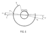
- ⁇ A cross-section of the outlet 38 taken along line C-C' is illustrated in FIG. 5 .
- the first slot 58 is formed above the radial axis (R) of the outlet 38 at a predetermined first angle ( ⁇ 1), for example approximately 6.50 degrees (6.50°).
- the inner housing assembly 32 may further include an inner housing cover 60 that extends between the outlet 38 and the cooling air inlet 42, as illustrated in FIGS. 1-3 .
- the inner housing cover 60 includes a first cover end and a second cover end.
- the first cover end is coupled to an outer portion of the outlet 38 using, for example, one or more bolts
- the second cover end is fitted into the groove 50 of the cooing air inlet 42 and is disposed against an inner surface of the outer lip 52.
- the outer lip 52 may support the inner housing cover 60, and may prevent the second cover end from becoming detached from the cooing air inlet 42.
- the slots may also formed at locations of the outlet 38 such that movement of the inner housing assembly 38 along the axial direction is limited by contact between an inner edge surrounding the slot 58, 58' and a bolt disposed through the slot 58, 58'
- the ram fan assembly 10 may further include one or more brackets 62 that couple together the motor/bearing housing 30 and the inner housing assembly 32.
- first and second brackets 62 are coupled to inner walls of the motor/bearing housing 30 and the inner housing assembly 32 to prevent separation of the motor/bearing housing 30 from the inner housing assembly 32.
- a joint 65 exists where the motor/bearing housing 30 contacts the inner bearing assembly 32.
- the bracket 62 may extend horizontally, i.e., along the X-axis, across the joint 65 to prevent the motor/bearing housing 30 and inner bearing assembly 32 from disconnecting thereat.
- the one or more brackets 62 maintain coupling of the motor/bearing housing 30 and the inner housing assembly 32 at the joint 65.
- the bracket 62 includes a body that extends between a first end 64 and a second end 66.
- the first end 64 may be coupled against an inner surface of the motor/bearing housing 30, and the second end 66 may be coupled against an inner surface of the inner housing assembly 32.
- the bracket 62 is formed from, for example, aluminum.
- the first end 64 includes a horizontal channel 68 that extends horizontally into the bracket 62 to receive a horizontal bolt 70.
- the second end 66 includes a vertical channel 72 that extends perpendicular to the horizontal channel 68 and into the bracket 62 to receive a vertical bolt 74.
- the horizontal channel 68 of the bracket 62 may be aligned with the hole formed in the motor/bearing housing 30, while the vertical channel 72 of the bracket 62 may be aligned with one of the first or second slots 58, 58' formed in the outlet 38 of the inner housing assembly 32. Accordingly, the horizontal bolt 70 may be disposed through the hole and into horizontal channel 68 to fasten the first end 64 of the bracket 62 to the motor/bearing housing 30, and the vertical bolt 74 may be disposed through the slot 58, 58' and into vertical channel 72 to fasten the second end 66 of the bracket 62 to the inner housing assembly 32.
- the bracket 62 may further include one or more helical coil inserts 76 that support a P-clamp (not shown), which is used to provide strain relief to the wires 55 fed through the motor/bearing housing 30 and the inner housing assembly 32.
- the slots 58, 58' may be formed such that a clearance exists between a surface of the outlet 38 and the vertical bolt 74 to tolerate vibration from the inner housing assembly 32.
- the slots 58, 58' may have an axial clearance distance (dA) ranging from approximately 0.036 inches (approximately 0.091 cm) to approximately 0.014 inches (approximately 0.035 cm), and a radial clearance distance (dR) ranging from approximately 0.104 inches (approximately 0.264 cm) to approximately 0.082 inches (approximately 0.208 cm).
- At least one embodiment of the present inventive teachings includes a bracket having a first end coupled to the motor/bearing housing and a second end coupled to the inner housing assembly. Accordingly, the bracket may prevent the inner housing assembly from disengaging from the motor/bearing housing as air flow generated by the RAF flows within the RAF ram fan assembly.
Landscapes
- Engineering & Computer Science (AREA)
- Mechanical Engineering (AREA)
- General Engineering & Computer Science (AREA)
- Chemical & Material Sciences (AREA)
- Combustion & Propulsion (AREA)
- Power Engineering (AREA)
- Aviation & Aerospace Engineering (AREA)
- Structures Of Non-Positive Displacement Pumps (AREA)
- Motor Or Generator Frames (AREA)
Abstract
Description
- The present inventive teachings relate generally to a ram fan assembly, and more particularly, an inner housing assembly included with a ram fan assembly.
- Ram air fan (RAF) assemblies traditionally include a motor/bearing housing and an inner housing assembly. The motor/bearing housing typically contains one or more bearings coupled to a shaft for driving a RAF unit, and a motor coupled to the shaft for generating rotation thereof. The inner housing assembly includes an inlet connected to a cool air duct and an outlet connected in fluid communication with the motor/bearing housing to deliver cool air over the motor and/or bearings to prevent over-heating.
- During operation of the RAF assembly, the ram fan assembly generates a ram air flow, which flows across the outer surface of the motor/bearing housing and the inner housing assembly. As the speed of the ram air flow increases, the inner housing assembly may realize a shear force that promotes the inner housing assembly to move laterally away from the motor/bearing housing. Consequently, the shear force may cause the outlet of inner housing assembly to become disengaged from motor/bearing housing.
- According to an embodiment of the present inventive teachings, a ram air fan assembly comprises a motor/bearing housing that extends along a horizontal length of the ram air fan assembly. An inner housing assembly is in fluid communication with the motor/bearing housing to define a joint therebetween. The inner housing assembly includes first and second ellipse-shaped slots. The first slot is positioned at a first angle with respect to a radial axis of the inner housing assembly that is perpendicular to the horizontal length. The second slot positioned at a second angle with respect to the radial axis such that the second angle is different from the first angle. Each slot extends along a first direction parallel to the horizontal length to define an axial width and extends along a radial axis to define a radial width being greater than the axial width. The ram air fan further includes first and second brackets. Each of the first and second brackets include a first end coupled to the motor/bearing housing and a second end coupled to the inner housing assembly to maintain coupling of the motor/bearing housing and the inner housing assembly at the joint. The second end of the first and second brackets includes a vertical channel aligned with one of the first and second slot. A first bolt is disposed through the first slot and into the vertical channel of the first bracket and a second bolt is disposed through the second slot and into the vertical channel of the second bracket. The first and second bolts couple the second end of the first and second brackets to the inner housing assembly.
- In another embodiment, an inner housing assembly of a ram fan assembly comprises a cool air inlet to receive an air flow, an inner duct and an outlet. The inner duct extends horizontally between a first end and a second end to define a horizontal length. The first end is formed in fluid communication with the cool air inlet to receive the air flow therefrom. The outlet is formed in fluid communication with the second end of the inner duct to receive the air flow delivered therefrom. The outlet includes at least one slot formed therethrough to receive a bolt that couples the outlet to a bracket. The at least one slot is shaped as an ellipse that extends along a first direction parallel to the horizontal length to define an axial width and along a second direction perpendicular to the horizontal width to define a radial width being greater than the axial width.
- In still another embodiment, a bracket to couple an inner housing assembly to a motor/bearing housing of a ram fan assembly comprises a body extending between first and second ends in a first direction extending parallel to a horizontal length of the ram fan assembly. A first channel is formed in the first end, and is configured to receive a first bolt to couple the first end to the motor/bearing housing. A second channel is formed in the second end. The second channel is configured to receive a second bolt to couple the second end to the inner housing assembly.
- The subject matter which is regarded as the inventive teachings is particularly pointed out and distinctly claimed in the claims at the conclusion of the specification. The foregoing and other features of the inventive teachings are apparent from the following detailed description taken in conjunction with the accompanying drawings in which:
-
FIG. 1 is a diagram illustrating a ram fan assembly according to an embodiment; -
FIG. 2 is a diagram illustrating an interior of the ram fan assembly shown inFIG. 2 ; -
FIG. 3 is a diagram illustrating an inner housing assembly of the ram fan assembly shown inFIGS. 1 and2 ; -
FIG. 4 is a diagram illustrating slots formed in an outlet of the inner housing assembly illustrated inFIG. 3 ; -
FIG. 5 is a cross-section of an outlet of the inner housing assembly illustrated inFIG. 3 taken along C-C' according to an embodiment; -
FIG. 6 is a diagram of bracket included with the ram fan assembly according to an embodiment; and -
FIGS. 7A-7B illustrate a clearance between a surface of the outlet and a bolt that fastens the inner housing bracket according to an embodiment. - Referring now to
FIG. 1 , a view of aram fan assembly 10 is illustrated according to an embodiment. Theram fan assembly 10 includes anouter housing 11 that extends along a horizontal axis (A), i.e., X-axis direction, between afan inlet 14 and afan outlet 16. Theram fan assembly 10 includes a ram air fan (RAF) 12 located at thefan inlet 14. A ram air flow (AF) flows into thefan inlet 14 and through an air pathway extending through the interior of theouter housing 11. The ram air flow (AF) may flow to a heat exchanger (not depicted) and/or overboard through thefan outlet 16. The outer housing may further include afan cap 13, which surrounds thefan inlet 14. - The
RAF 12 includes arotor assembly 18 and astrut assembly 20. Referring toFIG. 2 , therotor assembly 18 is rotatably connected to aRAF motor 21, for example an electric motor, via aRAF shaft 22. Therotor assembly 18 includes a plurality offan blades 24 extending radially from therotor assembly 18 toward thefan cap 13. The RAFmotor 21 drives theshaft 22, thereby rotating thefan blades 24 about theshaft 22 to urge additional air flow through thefan inlet 14. Thestrut assembly 20 is stationary with respect to therotor assembly 18 and includes a plurality ofstrut blades 26 fixed thereto. Eachstrut blade 26 extends radially from thestrut assembly 20 toward theouter housing 11. Acooling air duct 28 may be provided to drawcool air 29 into theouter housing 11 of theram fan assembly 10. The flow ofcool air 29 is driven generally via a pressure differential between thecooling air duct 28 and thefan inlet 14. - The
ram fan assembly 10 further includes a motor/bearinghousing 30 and aninner housing assembly 32. The motor/bearinghousing 30 is disposed within theouter housing 11 and extends between thestrut assembly 20 and theinner housing assembly 32. The motor/bearinghousing 30 may contain one or more bearings and theRAF motor 21 used to drive theshaft 22. More specifically, the motor/bearinghousing 30 assembly includes afirst end 34 coupled to thestrut assembly 20 and asecond end 36 coupled to anoutlet 38 of theinner housing assembly 32. Thesecond end 36 of the motor/bearinghousing 30 may include one or more holes for receiving a bolt that extends horizontally, i.e., parallel with the length of the motor/bearinghousing 30, and therethrough to fasten a bracket as discussed in greater detail below. Anouter layer 40 may wrap around and cover the motor/bearinghousing 30. Theouter layer 40 may be formed from metal including, but not limited to, titanium - The
inner housing assembly 32 includes acool air inlet 42, aconvolute 44, theoutlet 38, and aninner duct 46. Thecool air inlet 42 is coupled in fluid communication with thecooling air duct 28 to receive the flow ofcool air 29. Referring to an embodiment illustrated inFIG. 3 , thecool air inlet 42 includes an annular shape that defines anouter edge 48 having a first radius and an inner edge having a second radius that defines an inlet to receive the flow ofcool air 29. The second radius defining the inlet is less than the first radius of theouter edge 48. Thecool air inlet 42 may further include agroove 50 formed between the inlet and theouter edge 48. Thegroove 50 defines anouter lip 52 having a first length extending from theouter edge 48, and aninner lip 54 extending from the inner edge that defines the inlet. Theinner lip 54 may have a second length that is greater than the first length of theouter lip 52. - The convolute 44 provides a wiring path, which conveys one or
more wires 55 from theRAF motor 21 disposed in the motor/bearinghousing 30 to amotor controller 56 that controls operation of theRAF motor 21. Theinner duct 44 connects the coolingair inlet 42 and theoutlet 38 with one another. In at least one embodiment, a first end of theinner duct 46 is fitted into the inlet defined by theinner lip 54 of the coolingair inlet 42, and a second end of theinner duct 46 is coupled in fluid communication with theoutlet 38. Accordingly,cool air 29 drawn from thecool air duct 28 may flow into the coolingair inlet 42 and to theoutlet 38. - As discussed above, the
outlet 38 is in fluid communication with the motor/bearing housing 30 (seeFIG. 2 ). Theoutlet 38 may have a conical shape such that the radial portion that connects to the motor/bearinghousing 30 has a greater radius than the radial portion connected to theinner duct 46. The flow ofcool air 29 may be drawn through the coolingair duct 28, directed through theinner duct 46 and exhausted from theoutlet 38 into the motor/bearinghousing 30 to flow across theRAF motor 21 and bearings. Accordingly, heat realized by themotor 21 and bearings located in the motor/bearinghousing 30 may be reduced. - The
outlet 38 may further include one ormore slots 58 for receiving a bolt that extends therethrough to fasten a bracket, as discussed in greater detail below. In at least one embodiment, theoutlet 38 includes first andsecond slots 58, 58'. The slots may be shaped as an ellipse, for example an oval-shape. The slots may also formed at locations of the outlet such that movement of theinner housing assembly 38 along the axial direction is limited by contact between an inner edge surround the slot and a bolt disposed through theslot 58, 58'. More specifically, since a bolt is disposed through arespective slot 58, 58', theinner housing assembly 38 may be inhibited from moving in the axis direction when the inner edge surrounding theslot 58, 58' makes contact against the bolt. Hence, the bolt prevents theinner housing assembly 38 from moving therebeyond in the axis direction. Therefore, the bolts may be formed in theoutlet 38 such that the inner housing is inhibited from applying excessive force to the coolingair duct 28. - Referring to
FIG. 4 , eachslot 58, 58' extends along a first direction parallel to the horizontal length to define an axial width, and a second direction perpendicular to the horizontal length to define a radial width being greater than the axial width. The axial width may range from approximately 0.2 inches (0.508 cm) to approximately 0.3 inches (0.762 cm), and the radial width may range from approximately 0.35 inches (0.889 cm) to approximately 0.4 inches (1.016 cm). More specifically, theslots 58, 58' may have an axial width (wA) of approximately 0.240 inches (approximately 0.60 cm), and a radial width (wR) of approximately 0.375 inches (approximately 0.95 cm). Accordingly, the inner housing assembly may be afforded slightly more clearance along the radial direction, i.e., a direction parallel to the radial axis (R) than in the axial direction, i.e., the direction along the horizontal axis (A), as discussed in greater detail below. - The
slots 58, 58' may also be off-set from one another by a predetermined angle (θ). A cross-section of theoutlet 38 taken along line C-C' is illustrated inFIG. 5 . Thefirst slot 58 is formed above the radial axis (R) of theoutlet 38 at a predetermined first angle (θ1), for example approximately 6.50 degrees (6.50°). The second slot 58' is formed below the radial axis (R) at a predetermined second angle (θ2), for example 11.5°. Accordingly, the first andsecond slots 58, 58' may be offset from one another by approximately 18.0°, i.e., θ = θ1 + θ2. - The
inner housing assembly 32 may further include aninner housing cover 60 that extends between theoutlet 38 and the coolingair inlet 42, as illustrated inFIGS. 1-3 . Theinner housing cover 60 includes a first cover end and a second cover end. In at least one embodiment, the first cover end is coupled to an outer portion of theoutlet 38 using, for example, one or more bolts The second cover end is fitted into thegroove 50 of the cooingair inlet 42 and is disposed against an inner surface of theouter lip 52. Accordingly, theouter lip 52 may support theinner housing cover 60, and may prevent the second cover end from becoming detached from the cooingair inlet 42. As discussed above, the slots may also formed at locations of theoutlet 38 such that movement of theinner housing assembly 38 along the axial direction is limited by contact between an inner edge surrounding theslot 58, 58' and a bolt disposed through theslot 58, 58' - The
ram fan assembly 10 may further include one ormore brackets 62 that couple together the motor/bearinghousing 30 and theinner housing assembly 32. In at least one embodiment, first andsecond brackets 62 are coupled to inner walls of the motor/bearinghousing 30 and theinner housing assembly 32 to prevent separation of the motor/bearinghousing 30 from theinner housing assembly 32. - Referring to
FIG. 6 , a joint 65 exists where the motor/bearinghousing 30 contacts theinner bearing assembly 32. Thebracket 62 may extend horizontally, i.e., along the X-axis, across the joint 65 to prevent the motor/bearinghousing 30 andinner bearing assembly 32 from disconnecting thereat. In other words, the one ormore brackets 62 maintain coupling of the motor/bearinghousing 30 and theinner housing assembly 32 at the joint 65. - The
bracket 62 includes a body that extends between afirst end 64 and asecond end 66. Thefirst end 64 may be coupled against an inner surface of the motor/bearinghousing 30, and thesecond end 66 may be coupled against an inner surface of theinner housing assembly 32. In at least one embodiment, thebracket 62 is formed from, for example, aluminum. Thefirst end 64 includes ahorizontal channel 68 that extends horizontally into thebracket 62 to receive ahorizontal bolt 70. Thesecond end 66 includes avertical channel 72 that extends perpendicular to thehorizontal channel 68 and into thebracket 62 to receive avertical bolt 74. Thehorizontal channel 68 of thebracket 62 may be aligned with the hole formed in the motor/bearinghousing 30, while thevertical channel 72 of thebracket 62 may be aligned with one of the first orsecond slots 58, 58' formed in theoutlet 38 of theinner housing assembly 32. Accordingly, thehorizontal bolt 70 may be disposed through the hole and intohorizontal channel 68 to fasten thefirst end 64 of thebracket 62 to the motor/bearinghousing 30, and thevertical bolt 74 may be disposed through theslot 58, 58' and intovertical channel 72 to fasten thesecond end 66 of thebracket 62 to theinner housing assembly 32. Thebracket 62 may further include one or more helical coil inserts 76 that support a P-clamp (not shown), which is used to provide strain relief to thewires 55 fed through the motor/bearinghousing 30 and theinner housing assembly 32. - As illustrated in
FIGS. 7A-7B , theslots 58, 58' may be formed such that a clearance exists between a surface of theoutlet 38 and thevertical bolt 74 to tolerate vibration from theinner housing assembly 32. In at least one embodiment, for example, theslots 58, 58' may have an axial clearance distance (dA) ranging from approximately 0.036 inches (approximately 0.091 cm) to approximately 0.014 inches (approximately 0.035 cm), and a radial clearance distance (dR) ranging from approximately 0.104 inches (approximately 0.264 cm) to approximately 0.082 inches (approximately 0.208 cm). The clearance distances (dA, dR), therefore, allow theslots 58, 58' to sustain tolerances, such as vibrations and movements from theinner housing assembly 32, without overstressing adjacent components and without allowing theinner housing assembly 32 to substantially move and become disengaged from the motor/bearinghousing 30. - As described in detail above, at least one embodiment of the present inventive teachings includes a bracket having a first end coupled to the motor/bearing housing and a second end coupled to the inner housing assembly. Accordingly, the bracket may prevent the inner housing assembly from disengaging from the motor/bearing housing as air flow generated by the RAF flows within the RAF ram fan assembly.
- While the present inventive teachings have been described in detail in connection with only a limited number of embodiments, it should be readily understood that the present inventive teachings are not limited to such disclosed embodiments. Rather, the inventive teachings may be modified to incorporate any number of variations, alterations, substitutions or equivalent arrangements not heretofore described, but which are commensurate with the scope of the invention. Additionally, while various embodiments of the present inventive teachings have been described, it is to be understood that features of the inventive teachings may include only some of the described embodiments. Accordingly, the inventive teachings are not to be seen as limited by the foregoing description.
Claims (13)
- A ram air fan assembly (10), comprising:a motor/bearing housing (30) extending along a horizontal length of the ram air fan assembly (30);an inner housing assembly (32) in fluid communication with the motor/bearing housing (30) to define a joint (65) therebetween, the inner housing assembly (32) including first and second ellipse-shaped slots (58, 58'), the first slot (58) positioned at a first angle (θ1) with respect to a radial axis of the inner housing assembly (32) that is perpendicular to the horizontal length, and the second slot (58') positioned at a second angle (θ2) with respect to the radial axis, the second angle (θ2) being different from the first angle (θ1), and each slot (58, 58') extending along a first direction parallel to the horizontal length to define an axial width (wA) and extending along a radial axis to define a radial width (wR) being greater than the axial width (wA);first and second brackets (62), each of the first and second brackets (62) including a first end (64) coupled to the motor/bearing housing (30) and a second end (66) coupled to the inner housing assembly (32) to maintain coupling of the motor/bearing housing (30) and the inner housing assembly (32) at the joint (65), the second end (66) of the first and second brackets (62) including a vertical channel (72) aligned with one of the first and second slots (58, 58a); anda first bolt (74) disposed through the first slot (58) and into the vertical channel (72) of the first bracket (62) and a second bolt (74) disposed through the second slot (58') and into the vertical channel (72) of the second bracket (62), the first and second bolts (74) coupling the second end (66) of the first and second brackets (62) to the inner housing assembly (32).
- The ram air fan assembly of claim 1, wherein the motor/bearing assembly (30) includes at least one hole formed therethrough, and the first end (64) of the bracket (62) includes a horizontal channel (68) formed in a horizontal direction parallel to the horizontal length.
- The ram air fan assembly of claim 2, wherein the horizontal channel (68) is aligned with the at least one hole, a third bolt (70) disposed in the at least one hole and the horizontal channel (68) to couple the motor/bearing housing (30) to the first end (64) of the bracket (62).
- The ram fan assembly of claim 3, wherein each of the first and second slots (58, 58') defines at least one clearance distance between a respective portion of the inner housing assembly (32) and the respective bolt (74).
- The ram fan assembly of claim 4, wherein the at least one clearance distance includes a first clearance distance (dA) extending in an axial direction and a second clearance distance (dR) different from the first clearance distance (dA) extending in a radial direction perpendicular to the axial direction.
- The ram fan assembly of claim 5, wherein the first clearance distance (dA) is less than the second clearance distance (dR).
- The ram fan assembly of claim 6, wherein the first clearance distance ranges (dA) from 0.036 inches (0.09144 cm) to 0.014 inches (0.03556 cm), and the second clearance distance (dR) ranges from 0.104 inches (0.26416 cm) to 0.082 inches (0.20828 cm).
- An inner housing assembly (32) of a ram fan assembly, the inner housing assembly (32) comprising:a cool air inlet (42) to receive an air flow;an inner duct (46) extending horizontally between a first end and a second end to define a horizontal length, the first end formed in fluid communication with the cool air inlet (42) to receive the air flow therefrom; andan outlet (38) formed in fluid communication with the second end of the inner duct (46) to receive the air flow delivered therefrom, the outlet (38) including at least one slot (58, 58') formed therethrough to receive a bolt (74) that couples the outlet (38) to a bracket (62), the at least one slot (58, 58') shaped as an ellipse that extends along a first direction parallel to the horizontal length to define an axial width (wA) and along a second direction perpendicular to the horizontal width to define a radial width (wR) being greater than the axial width (wA).
- The inner housing assembly of claim 8, wherein the at least one slot includes a first slot (58) and a second slot (58') formed opposite the first slot (58).
- The inner housing assembly of claim 9, wherein the first slot (58) is positioned at a first angle with respect to a radial axis of the outlet (38) and the second slot (58') is positioned at a second angle (θ2) with respect to the radial axis, the second angle (θ2) being different from the first angle (θ1).
- The ram fan assembly or inner housing assembly of any preceding claim, wherein the first angle (θ1) ranges from 6.0 degrees to 7.0 degrees and the second angle (θ2) ranges from 11.0 degrees to 12.0 degrees.
- The ram fan assembly or inner housing assembly of claim 11, wherein the first slot (58') is formed above the radial axis at the first angle (θ1), and the second slot (58) is formed below the radial axis at the second angle (θ2) such that an angle differential between the first and second slots (58, 58') ranges from 17.0 degrees to 19.0 degrees.
- The ram fan assembly or inner housing assembly of any preceding claim, wherein the axial width (wA) ranges from 0.2 inches (0.508 cm) to 0.3 inches (0.762 cm), and the radial width (wR) ranges from 0.35 inches (0.889 cm) to 0.4 inches (1.016 cm).
Applications Claiming Priority (1)
| Application Number | Priority Date | Filing Date | Title |
|---|---|---|---|
| US13/847,278 US9790894B2 (en) | 2013-03-19 | 2013-03-19 | Inner housing assembly including retention slots |
Publications (3)
| Publication Number | Publication Date |
|---|---|
| EP2781759A2 true EP2781759A2 (en) | 2014-09-24 |
| EP2781759A3 EP2781759A3 (en) | 2014-12-10 |
| EP2781759B1 EP2781759B1 (en) | 2016-09-28 |
Family
ID=50343628
Family Applications (1)
| Application Number | Title | Priority Date | Filing Date |
|---|---|---|---|
| EP14160312.6A Active EP2781759B1 (en) | 2013-03-19 | 2014-03-17 | Inner housing assembly including retention slots |
Country Status (2)
| Country | Link |
|---|---|
| US (1) | US9790894B2 (en) |
| EP (1) | EP2781759B1 (en) |
Family Cites Families (5)
| Publication number | Priority date | Publication date | Assignee | Title |
|---|---|---|---|---|
| US4092036A (en) | 1975-12-15 | 1978-05-30 | Kabushiki Kaisha Suiken | Pipe junction holder |
| DE10036575A1 (en) * | 2000-07-27 | 2002-02-07 | Bosch Gmbh Robert | Device for the elastic mounting of a hydraulic unit of a vehicle brake system in a vehicle |
| US7798768B2 (en) * | 2006-10-25 | 2010-09-21 | Siemens Energy, Inc. | Turbine vane ID support |
| US8459966B2 (en) | 2010-07-19 | 2013-06-11 | Hamilton Sundstrand Corporation | Ram air fan motor cooling |
| US10428832B2 (en) * | 2012-08-06 | 2019-10-01 | United Technologies Corporation | Stator anti-rotation lug |
-
2013
- 2013-03-19 US US13/847,278 patent/US9790894B2/en active Active
-
2014
- 2014-03-17 EP EP14160312.6A patent/EP2781759B1/en active Active
Non-Patent Citations (1)
| Title |
|---|
| None |
Also Published As
| Publication number | Publication date |
|---|---|
| EP2781759A3 (en) | 2014-12-10 |
| US20140283521A1 (en) | 2014-09-25 |
| US9790894B2 (en) | 2017-10-17 |
| EP2781759B1 (en) | 2016-09-28 |
Similar Documents
| Publication | Publication Date | Title |
|---|---|---|
| EP2409919B1 (en) | Ram air fan motor cooling | |
| CN108368852B (en) | Electric centrifugal compressors for turbine engines or aircraft | |
| US8446056B2 (en) | Electric machine cooling system and method | |
| EP2602917B1 (en) | Dynamo-electric machine | |
| US10418882B2 (en) | Traction motor with cooling fan for improved cooling flow | |
| US9716420B2 (en) | Fan and electric machine assembly and methods therefor | |
| US10221935B2 (en) | Speed reduction apparatus | |
| US9638199B2 (en) | Ram air fan inlet shroud | |
| US20150008771A1 (en) | Motor having cooling means | |
| EP3713051B1 (en) | Rotor assembly and method of cooling | |
| US20140312167A1 (en) | Ram Air Fan Mounting Bracket | |
| CN103967809A (en) | Blower fan | |
| EP3352344A1 (en) | Vehicular ac power generator | |
| US11441568B2 (en) | Electric motor comprising pressing cooling air conveyance and method for cooling components of the electric motor | |
| EP3159507B1 (en) | Oil supply conduit through stator lamination stack for electrified turbocharger | |
| US9914542B2 (en) | Ram air fan housing | |
| US10358028B2 (en) | Air-cooled electric propulsion unit | |
| CN106464084A (en) | rotating electrical machine | |
| EP2781759B1 (en) | Inner housing assembly including retention slots | |
| EP3550149A1 (en) | Structurally improved ram fan inlet shroud | |
| US10443619B2 (en) | Motor housing assembly for a cabin air compressor | |
| US12234836B1 (en) | Fan | |
| US11219905B2 (en) | Cooling device for a drive of a solid bowl screw centrifuge | |
| US9831745B2 (en) | Electric machine | |
| US20230116543A1 (en) | Rotary machine |
Legal Events
| Date | Code | Title | Description |
|---|---|---|---|
| PUAI | Public reference made under article 153(3) epc to a published international application that has entered the european phase |
Free format text: ORIGINAL CODE: 0009012 |
|
| 17P | Request for examination filed |
Effective date: 20140317 |
|
| AK | Designated contracting states |
Kind code of ref document: A2 Designated state(s): AL AT BE BG CH CY CZ DE DK EE ES FI FR GB GR HR HU IE IS IT LI LT LU LV MC MK MT NL NO PL PT RO RS SE SI SK SM TR |
|
| AX | Request for extension of the european patent |
Extension state: BA ME |
|
| RIN1 | Information on inventor provided before grant (corrected) |
Inventor name: FISKE, WILLIAM R. Inventor name: DORMAN, DAVID A. Inventor name: CHRABASCZ, ERIC |
|
| PUAL | Search report despatched |
Free format text: ORIGINAL CODE: 0009013 |
|
| AK | Designated contracting states |
Kind code of ref document: A3 Designated state(s): AL AT BE BG CH CY CZ DE DK EE ES FI FR GB GR HR HU IE IS IT LI LT LU LV MC MK MT NL NO PL PT RO RS SE SI SK SM TR |
|
| AX | Request for extension of the european patent |
Extension state: BA ME |
|
| RIC1 | Information provided on ipc code assigned before grant |
Ipc: F04D 19/00 20060101AFI20141106BHEP Ipc: B64D 13/00 20060101ALI20141106BHEP Ipc: F04D 25/06 20060101ALI20141106BHEP Ipc: F04D 29/64 20060101ALI20141106BHEP |
|
| R17P | Request for examination filed (corrected) |
Effective date: 20150610 |
|
| RBV | Designated contracting states (corrected) |
Designated state(s): AL AT BE BG CH CY CZ DE DK EE ES FI FR GB GR HR HU IE IS IT LI LT LU LV MC MK MT NL NO PL PT RO RS SE SI SK SM TR |
|
| GRAP | Despatch of communication of intention to grant a patent |
Free format text: ORIGINAL CODE: EPIDOSNIGR1 |
|
| INTG | Intention to grant announced |
Effective date: 20151029 |
|
| GRAP | Despatch of communication of intention to grant a patent |
Free format text: ORIGINAL CODE: EPIDOSNIGR1 |
|
| INTG | Intention to grant announced |
Effective date: 20160412 |
|
| GRAS | Grant fee paid |
Free format text: ORIGINAL CODE: EPIDOSNIGR3 |
|
| GRAA | (expected) grant |
Free format text: ORIGINAL CODE: 0009210 |
|
| AK | Designated contracting states |
Kind code of ref document: B1 Designated state(s): AL AT BE BG CH CY CZ DE DK EE ES FI FR GB GR HR HU IE IS IT LI LT LU LV MC MK MT NL NO PL PT RO RS SE SI SK SM TR |
|
| REG | Reference to a national code |
Ref country code: GB Ref legal event code: FG4D |
|
| REG | Reference to a national code |
Ref country code: CH Ref legal event code: EP |
|
| REG | Reference to a national code |
Ref country code: AT Ref legal event code: REF Ref document number: 833028 Country of ref document: AT Kind code of ref document: T Effective date: 20161015 |
|
| REG | Reference to a national code |
Ref country code: IE Ref legal event code: FG4D |
|
| REG | Reference to a national code |
Ref country code: DE Ref legal event code: R096 Ref document number: 602014003923 Country of ref document: DE |
|
| REG | Reference to a national code |
Ref country code: LT Ref legal event code: MG4D |
|
| PG25 | Lapsed in a contracting state [announced via postgrant information from national office to epo] |
Ref country code: FI Free format text: LAPSE BECAUSE OF FAILURE TO SUBMIT A TRANSLATION OF THE DESCRIPTION OR TO PAY THE FEE WITHIN THE PRESCRIBED TIME-LIMIT Effective date: 20160928 Ref country code: NO Free format text: LAPSE BECAUSE OF FAILURE TO SUBMIT A TRANSLATION OF THE DESCRIPTION OR TO PAY THE FEE WITHIN THE PRESCRIBED TIME-LIMIT Effective date: 20161228 Ref country code: LT Free format text: LAPSE BECAUSE OF FAILURE TO SUBMIT A TRANSLATION OF THE DESCRIPTION OR TO PAY THE FEE WITHIN THE PRESCRIBED TIME-LIMIT Effective date: 20160928 Ref country code: RS Free format text: LAPSE BECAUSE OF FAILURE TO SUBMIT A TRANSLATION OF THE DESCRIPTION OR TO PAY THE FEE WITHIN THE PRESCRIBED TIME-LIMIT Effective date: 20160928 Ref country code: HR Free format text: LAPSE BECAUSE OF FAILURE TO SUBMIT A TRANSLATION OF THE DESCRIPTION OR TO PAY THE FEE WITHIN THE PRESCRIBED TIME-LIMIT Effective date: 20160928 |
|
| REG | Reference to a national code |
Ref country code: NL Ref legal event code: MP Effective date: 20160928 |
|
| REG | Reference to a national code |
Ref country code: AT Ref legal event code: MK05 Ref document number: 833028 Country of ref document: AT Kind code of ref document: T Effective date: 20160928 |
|
| REG | Reference to a national code |
Ref country code: FR Ref legal event code: PLFP Year of fee payment: 4 |
|
| PG25 | Lapsed in a contracting state [announced via postgrant information from national office to epo] |
Ref country code: GR Free format text: LAPSE BECAUSE OF FAILURE TO SUBMIT A TRANSLATION OF THE DESCRIPTION OR TO PAY THE FEE WITHIN THE PRESCRIBED TIME-LIMIT Effective date: 20161229 Ref country code: SE Free format text: LAPSE BECAUSE OF FAILURE TO SUBMIT A TRANSLATION OF THE DESCRIPTION OR TO PAY THE FEE WITHIN THE PRESCRIBED TIME-LIMIT Effective date: 20160928 Ref country code: NL Free format text: LAPSE BECAUSE OF FAILURE TO SUBMIT A TRANSLATION OF THE DESCRIPTION OR TO PAY THE FEE WITHIN THE PRESCRIBED TIME-LIMIT Effective date: 20160928 Ref country code: LV Free format text: LAPSE BECAUSE OF FAILURE TO SUBMIT A TRANSLATION OF THE DESCRIPTION OR TO PAY THE FEE WITHIN THE PRESCRIBED TIME-LIMIT Effective date: 20160928 |
|
| PG25 | Lapsed in a contracting state [announced via postgrant information from national office to epo] |
Ref country code: RO Free format text: LAPSE BECAUSE OF FAILURE TO SUBMIT A TRANSLATION OF THE DESCRIPTION OR TO PAY THE FEE WITHIN THE PRESCRIBED TIME-LIMIT Effective date: 20160928 Ref country code: EE Free format text: LAPSE BECAUSE OF FAILURE TO SUBMIT A TRANSLATION OF THE DESCRIPTION OR TO PAY THE FEE WITHIN THE PRESCRIBED TIME-LIMIT Effective date: 20160928 |
|
| PG25 | Lapsed in a contracting state [announced via postgrant information from national office to epo] |
Ref country code: ES Free format text: LAPSE BECAUSE OF FAILURE TO SUBMIT A TRANSLATION OF THE DESCRIPTION OR TO PAY THE FEE WITHIN THE PRESCRIBED TIME-LIMIT Effective date: 20160928 Ref country code: AT Free format text: LAPSE BECAUSE OF FAILURE TO SUBMIT A TRANSLATION OF THE DESCRIPTION OR TO PAY THE FEE WITHIN THE PRESCRIBED TIME-LIMIT Effective date: 20160928 Ref country code: SM Free format text: LAPSE BECAUSE OF FAILURE TO SUBMIT A TRANSLATION OF THE DESCRIPTION OR TO PAY THE FEE WITHIN THE PRESCRIBED TIME-LIMIT Effective date: 20160928 Ref country code: BE Free format text: LAPSE BECAUSE OF FAILURE TO SUBMIT A TRANSLATION OF THE DESCRIPTION OR TO PAY THE FEE WITHIN THE PRESCRIBED TIME-LIMIT Effective date: 20160928 Ref country code: CZ Free format text: LAPSE BECAUSE OF FAILURE TO SUBMIT A TRANSLATION OF THE DESCRIPTION OR TO PAY THE FEE WITHIN THE PRESCRIBED TIME-LIMIT Effective date: 20160928 Ref country code: PT Free format text: LAPSE BECAUSE OF FAILURE TO SUBMIT A TRANSLATION OF THE DESCRIPTION OR TO PAY THE FEE WITHIN THE PRESCRIBED TIME-LIMIT Effective date: 20170130 Ref country code: PL Free format text: LAPSE BECAUSE OF FAILURE TO SUBMIT A TRANSLATION OF THE DESCRIPTION OR TO PAY THE FEE WITHIN THE PRESCRIBED TIME-LIMIT Effective date: 20160928 Ref country code: SK Free format text: LAPSE BECAUSE OF FAILURE TO SUBMIT A TRANSLATION OF THE DESCRIPTION OR TO PAY THE FEE WITHIN THE PRESCRIBED TIME-LIMIT Effective date: 20160928 Ref country code: BG Free format text: LAPSE BECAUSE OF FAILURE TO SUBMIT A TRANSLATION OF THE DESCRIPTION OR TO PAY THE FEE WITHIN THE PRESCRIBED TIME-LIMIT Effective date: 20161228 Ref country code: IS Free format text: LAPSE BECAUSE OF FAILURE TO SUBMIT A TRANSLATION OF THE DESCRIPTION OR TO PAY THE FEE WITHIN THE PRESCRIBED TIME-LIMIT Effective date: 20170128 |
|
| REG | Reference to a national code |
Ref country code: DE Ref legal event code: R097 Ref document number: 602014003923 Country of ref document: DE |
|
| PG25 | Lapsed in a contracting state [announced via postgrant information from national office to epo] |
Ref country code: IT Free format text: LAPSE BECAUSE OF FAILURE TO SUBMIT A TRANSLATION OF THE DESCRIPTION OR TO PAY THE FEE WITHIN THE PRESCRIBED TIME-LIMIT Effective date: 20160928 |
|
| PG25 | Lapsed in a contracting state [announced via postgrant information from national office to epo] |
Ref country code: DK Free format text: LAPSE BECAUSE OF FAILURE TO SUBMIT A TRANSLATION OF THE DESCRIPTION OR TO PAY THE FEE WITHIN THE PRESCRIBED TIME-LIMIT Effective date: 20160928 |
|
| PLBE | No opposition filed within time limit |
Free format text: ORIGINAL CODE: 0009261 |
|
| STAA | Information on the status of an ep patent application or granted ep patent |
Free format text: STATUS: NO OPPOSITION FILED WITHIN TIME LIMIT |
|
| 26N | No opposition filed |
Effective date: 20170629 |
|
| REG | Reference to a national code |
Ref country code: DE Ref legal event code: R119 Ref document number: 602014003923 Country of ref document: DE |
|
| REG | Reference to a national code |
Ref country code: CH Ref legal event code: PL |
|
| PG25 | Lapsed in a contracting state [announced via postgrant information from national office to epo] |
Ref country code: MC Free format text: LAPSE BECAUSE OF FAILURE TO SUBMIT A TRANSLATION OF THE DESCRIPTION OR TO PAY THE FEE WITHIN THE PRESCRIBED TIME-LIMIT Effective date: 20160928 Ref country code: SI Free format text: LAPSE BECAUSE OF FAILURE TO SUBMIT A TRANSLATION OF THE DESCRIPTION OR TO PAY THE FEE WITHIN THE PRESCRIBED TIME-LIMIT Effective date: 20160928 |
|
| REG | Reference to a national code |
Ref country code: IE Ref legal event code: MM4A |
|
| PG25 | Lapsed in a contracting state [announced via postgrant information from national office to epo] |
Ref country code: LU Free format text: LAPSE BECAUSE OF NON-PAYMENT OF DUE FEES Effective date: 20170317 Ref country code: DE Free format text: LAPSE BECAUSE OF NON-PAYMENT OF DUE FEES Effective date: 20171003 |
|
| REG | Reference to a national code |
Ref country code: FR Ref legal event code: PLFP Year of fee payment: 5 |
|
| PG25 | Lapsed in a contracting state [announced via postgrant information from national office to epo] |
Ref country code: CH Free format text: LAPSE BECAUSE OF NON-PAYMENT OF DUE FEES Effective date: 20170331 Ref country code: IE Free format text: LAPSE BECAUSE OF NON-PAYMENT OF DUE FEES Effective date: 20170317 Ref country code: LI Free format text: LAPSE BECAUSE OF NON-PAYMENT OF DUE FEES Effective date: 20170331 |
|
| PG25 | Lapsed in a contracting state [announced via postgrant information from national office to epo] |
Ref country code: MT Free format text: LAPSE BECAUSE OF NON-PAYMENT OF DUE FEES Effective date: 20170317 |
|
| PG25 | Lapsed in a contracting state [announced via postgrant information from national office to epo] |
Ref country code: AL Free format text: LAPSE BECAUSE OF FAILURE TO SUBMIT A TRANSLATION OF THE DESCRIPTION OR TO PAY THE FEE WITHIN THE PRESCRIBED TIME-LIMIT Effective date: 20160928 |
|
| PG25 | Lapsed in a contracting state [announced via postgrant information from national office to epo] |
Ref country code: HU Free format text: LAPSE BECAUSE OF FAILURE TO SUBMIT A TRANSLATION OF THE DESCRIPTION OR TO PAY THE FEE WITHIN THE PRESCRIBED TIME-LIMIT; INVALID AB INITIO Effective date: 20140317 |
|
| PG25 | Lapsed in a contracting state [announced via postgrant information from national office to epo] |
Ref country code: CY Free format text: LAPSE BECAUSE OF NON-PAYMENT OF DUE FEES Effective date: 20160928 |
|
| PG25 | Lapsed in a contracting state [announced via postgrant information from national office to epo] |
Ref country code: MK Free format text: LAPSE BECAUSE OF FAILURE TO SUBMIT A TRANSLATION OF THE DESCRIPTION OR TO PAY THE FEE WITHIN THE PRESCRIBED TIME-LIMIT Effective date: 20160928 |
|
| PG25 | Lapsed in a contracting state [announced via postgrant information from national office to epo] |
Ref country code: TR Free format text: LAPSE BECAUSE OF FAILURE TO SUBMIT A TRANSLATION OF THE DESCRIPTION OR TO PAY THE FEE WITHIN THE PRESCRIBED TIME-LIMIT Effective date: 20160928 |
|
| P01 | Opt-out of the competence of the unified patent court (upc) registered |
Effective date: 20230522 |
|
| PGFP | Annual fee paid to national office [announced via postgrant information from national office to epo] |
Ref country code: GB Payment date: 20260220 Year of fee payment: 13 |
|
| PGFP | Annual fee paid to national office [announced via postgrant information from national office to epo] |
Ref country code: FR Payment date: 20260219 Year of fee payment: 13 |