EP2781728A2 - Thrust reverser inner fixed structure with corner fitting - Google Patents
Thrust reverser inner fixed structure with corner fitting Download PDFInfo
- Publication number
- EP2781728A2 EP2781728A2 EP14159512.4A EP14159512A EP2781728A2 EP 2781728 A2 EP2781728 A2 EP 2781728A2 EP 14159512 A EP14159512 A EP 14159512A EP 2781728 A2 EP2781728 A2 EP 2781728A2
- Authority
- EP
- European Patent Office
- Prior art keywords
- corner fitting
- acoustic
- honeycomb core
- inner barrel
- barrel
- Prior art date
- Legal status (The legal status is an assumption and is not a legal conclusion. Google has not performed a legal analysis and makes no representation as to the accuracy of the status listed.)
- Withdrawn
Links
- 238000000034 method Methods 0.000 claims abstract description 27
- RTAQQCXQSZGOHL-UHFFFAOYSA-N Titanium Chemical compound [Ti] RTAQQCXQSZGOHL-UHFFFAOYSA-N 0.000 claims description 19
- 239000010936 titanium Substances 0.000 claims description 19
- 229910052719 titanium Inorganic materials 0.000 claims description 19
- 238000009792 diffusion process Methods 0.000 claims description 6
- 239000007788 liquid Substances 0.000 claims description 5
- 239000000853 adhesive Substances 0.000 claims description 4
- 230000001070 adhesive effect Effects 0.000 claims description 4
- 238000005266 casting Methods 0.000 claims description 3
- 238000003754 machining Methods 0.000 claims description 2
- 240000008042 Zea mays Species 0.000 claims 1
- 235000005824 Zea mays ssp. parviglumis Nutrition 0.000 claims 1
- 235000002017 Zea mays subsp mays Nutrition 0.000 claims 1
- 235000005822 corn Nutrition 0.000 claims 1
- 238000004519 manufacturing process Methods 0.000 abstract description 2
- 239000002131 composite material Substances 0.000 description 5
- 239000004593 Epoxy Substances 0.000 description 4
- 230000001413 cellular effect Effects 0.000 description 4
- OKTJSMMVPCPJKN-UHFFFAOYSA-N Carbon Chemical compound [C] OKTJSMMVPCPJKN-UHFFFAOYSA-N 0.000 description 3
- 238000005219 brazing Methods 0.000 description 3
- 238000010276 construction Methods 0.000 description 3
- 229910002804 graphite Inorganic materials 0.000 description 3
- 239000010439 graphite Substances 0.000 description 3
- 239000000463 material Substances 0.000 description 3
- 229910052751 metal Inorganic materials 0.000 description 3
- 239000002184 metal Substances 0.000 description 3
- 229920000049 Carbon (fiber) Polymers 0.000 description 2
- 229910052782 aluminium Inorganic materials 0.000 description 2
- XAGFODPZIPBFFR-UHFFFAOYSA-N aluminium Chemical compound [Al] XAGFODPZIPBFFR-UHFFFAOYSA-N 0.000 description 2
- 230000015572 biosynthetic process Effects 0.000 description 2
- 239000004917 carbon fiber Substances 0.000 description 2
- 238000005755 formation reaction Methods 0.000 description 2
- 238000009413 insulation Methods 0.000 description 2
- VNWKTOKETHGBQD-UHFFFAOYSA-N methane Chemical compound C VNWKTOKETHGBQD-UHFFFAOYSA-N 0.000 description 2
- 238000003466 welding Methods 0.000 description 2
- 239000010953 base metal Substances 0.000 description 1
- 238000001816 cooling Methods 0.000 description 1
- 230000007423 decrease Effects 0.000 description 1
- 238000005516 engineering process Methods 0.000 description 1
- -1 for example Chemical class 0.000 description 1
- 229910001026 inconel Inorganic materials 0.000 description 1
- 150000002739 metals Chemical class 0.000 description 1
- 230000001681 protective effect Effects 0.000 description 1
- 230000001629 suppression Effects 0.000 description 1
Images


Classifications
-
- F—MECHANICAL ENGINEERING; LIGHTING; HEATING; WEAPONS; BLASTING
- F02—COMBUSTION ENGINES; HOT-GAS OR COMBUSTION-PRODUCT ENGINE PLANTS
- F02K—JET-PROPULSION PLANTS
- F02K1/00—Plants characterised by the form or arrangement of the jet pipe or nozzle; Jet pipes or nozzles peculiar thereto
- F02K1/54—Nozzles having means for reversing jet thrust
- F02K1/56—Reversing jet main flow
-
- B—PERFORMING OPERATIONS; TRANSPORTING
- B21—MECHANICAL METAL-WORKING WITHOUT ESSENTIALLY REMOVING MATERIAL; PUNCHING METAL
- B21D—WORKING OR PROCESSING OF SHEET METAL OR METAL TUBES, RODS OR PROFILES WITHOUT ESSENTIALLY REMOVING MATERIAL; PUNCHING METAL
- B21D53/00—Making other particular articles
- B21D53/92—Making other particular articles other parts for aircraft
-
- B—PERFORMING OPERATIONS; TRANSPORTING
- B23—MACHINE TOOLS; METAL-WORKING NOT OTHERWISE PROVIDED FOR
- B23K—SOLDERING OR UNSOLDERING; WELDING; CLADDING OR PLATING BY SOLDERING OR WELDING; CUTTING BY APPLYING HEAT LOCALLY, e.g. FLAME CUTTING; WORKING BY LASER BEAM
- B23K1/00—Soldering, e.g. brazing, or unsoldering
- B23K1/0008—Soldering, e.g. brazing, or unsoldering specially adapted for particular articles or work
- B23K1/0018—Brazing of turbine parts
-
- B—PERFORMING OPERATIONS; TRANSPORTING
- B32—LAYERED PRODUCTS
- B32B—LAYERED PRODUCTS, i.e. PRODUCTS BUILT-UP OF STRATA OF FLAT OR NON-FLAT, e.g. CELLULAR OR HONEYCOMB, FORM
- B32B37/00—Methods or apparatus for laminating, e.g. by curing or by ultrasonic bonding
- B32B37/0038—Methods or apparatus for laminating, e.g. by curing or by ultrasonic bonding involving application of liquid to the layers prior to lamination, e.g. wet laminating
-
- B—PERFORMING OPERATIONS; TRANSPORTING
- B32—LAYERED PRODUCTS
- B32B—LAYERED PRODUCTS, i.e. PRODUCTS BUILT-UP OF STRATA OF FLAT OR NON-FLAT, e.g. CELLULAR OR HONEYCOMB, FORM
- B32B37/00—Methods or apparatus for laminating, e.g. by curing or by ultrasonic bonding
- B32B37/12—Methods or apparatus for laminating, e.g. by curing or by ultrasonic bonding characterised by using adhesives
-
- F—MECHANICAL ENGINEERING; LIGHTING; HEATING; WEAPONS; BLASTING
- F02—COMBUSTION ENGINES; HOT-GAS OR COMBUSTION-PRODUCT ENGINE PLANTS
- F02K—JET-PROPULSION PLANTS
- F02K1/00—Plants characterised by the form or arrangement of the jet pipe or nozzle; Jet pipes or nozzles peculiar thereto
- F02K1/54—Nozzles having means for reversing jet thrust
- F02K1/64—Reversing fan flow
- F02K1/70—Reversing fan flow using thrust reverser flaps or doors mounted on the fan housing
-
- F—MECHANICAL ENGINEERING; LIGHTING; HEATING; WEAPONS; BLASTING
- F02—COMBUSTION ENGINES; HOT-GAS OR COMBUSTION-PRODUCT ENGINE PLANTS
- F02K—JET-PROPULSION PLANTS
- F02K1/00—Plants characterised by the form or arrangement of the jet pipe or nozzle; Jet pipes or nozzles peculiar thereto
- F02K1/78—Other construction of jet pipes
- F02K1/82—Jet pipe walls, e.g. liners
- F02K1/827—Sound absorbing structures or liners
-
- F—MECHANICAL ENGINEERING; LIGHTING; HEATING; WEAPONS; BLASTING
- F05—INDEXING SCHEMES RELATING TO ENGINES OR PUMPS IN VARIOUS SUBCLASSES OF CLASSES F01-F04
- F05D—INDEXING SCHEME FOR ASPECTS RELATING TO NON-POSITIVE-DISPLACEMENT MACHINES OR ENGINES, GAS-TURBINES OR JET-PROPULSION PLANTS
- F05D2250/00—Geometry
- F05D2250/20—Three-dimensional
- F05D2250/28—Three-dimensional patterned
- F05D2250/283—Three-dimensional patterned honeycomb
-
- Y—GENERAL TAGGING OF NEW TECHNOLOGICAL DEVELOPMENTS; GENERAL TAGGING OF CROSS-SECTIONAL TECHNOLOGIES SPANNING OVER SEVERAL SECTIONS OF THE IPC; TECHNICAL SUBJECTS COVERED BY FORMER USPC CROSS-REFERENCE ART COLLECTIONS [XRACs] AND DIGESTS
- Y02—TECHNOLOGIES OR APPLICATIONS FOR MITIGATION OR ADAPTATION AGAINST CLIMATE CHANGE
- Y02T—CLIMATE CHANGE MITIGATION TECHNOLOGIES RELATED TO TRANSPORTATION
- Y02T50/00—Aeronautics or air transport
- Y02T50/60—Efficient propulsion technologies, e.g. for aircraft
-
- Y—GENERAL TAGGING OF NEW TECHNOLOGICAL DEVELOPMENTS; GENERAL TAGGING OF CROSS-SECTIONAL TECHNOLOGIES SPANNING OVER SEVERAL SECTIONS OF THE IPC; TECHNICAL SUBJECTS COVERED BY FORMER USPC CROSS-REFERENCE ART COLLECTIONS [XRACs] AND DIGESTS
- Y10—TECHNICAL SUBJECTS COVERED BY FORMER USPC
- Y10T—TECHNICAL SUBJECTS COVERED BY FORMER US CLASSIFICATION
- Y10T156/00—Adhesive bonding and miscellaneous chemical manufacture
- Y10T156/10—Methods of surface bonding and/or assembly therefor
-
- Y—GENERAL TAGGING OF NEW TECHNOLOGICAL DEVELOPMENTS; GENERAL TAGGING OF CROSS-SECTIONAL TECHNOLOGIES SPANNING OVER SEVERAL SECTIONS OF THE IPC; TECHNICAL SUBJECTS COVERED BY FORMER USPC CROSS-REFERENCE ART COLLECTIONS [XRACs] AND DIGESTS
- Y10—TECHNICAL SUBJECTS COVERED BY FORMER USPC
- Y10T—TECHNICAL SUBJECTS COVERED BY FORMER US CLASSIFICATION
- Y10T29/00—Metal working
- Y10T29/49—Method of mechanical manufacture
- Y10T29/4957—Sound device making
Definitions
- the invention relates to the field of protective systems for aircraft propulsion system components and in particular, to a liquid interface diffusion (LID) bonded titanium inner fixed structure (IFS) with bonded-in corner fitting for an aircraft engine nacelle system.
- LID liquid interface diffusion
- IFS titanium inner fixed structure
- a nacelle system is the aerodynamic structure that surrounds an aircraft engine. It includes parts commonly referred to as engine cowling, but the nacelle system typically includes other components as well including the inlet cowl, fan cowl, thrust reverser, core cowl and nozzle.
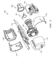
- FIG. 1 illustrates an assembled, complete aircraft propulsion assembly 100
- FIG. 2 shows an exploded view of the aircraft propulsion assembly 100 of FIG. 1
- components of the aircraft propulsion system include an engine assembly 102 at the tail end of which are an exhaust cone 104 and an exhaust nozzle 106.
- the forward end of the engine assembly 102 includes a nacelle inlet 110 having a nacelle inlet lip 112.
- Aft of the nacelle inlet 110 is a fan cowl 120 comprising fan cowl halves 122, 124.
- a thrust reverser 130 comprising thrust reverser halves 132, 134 is aft of the fan cowl 120.
- a pylon/strut assembly 140 connects the aforementioned component to a wing of an aircraft.
- the thrust reverser 130 includes an outer fixed structure, a translating sleeve, and an inner fixed structure as shown in FIG. 3 .
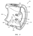
- FIG. 3 shows thrust reverser half 330 which exposes a one half section 332 of an inner fixed structure (IFS) formed in two "clam-shell" halves, only one clam-shell half being shown.
- IFS inner fixed structure
- the IFS section has a forward end 334 with an exterior surface 335 that faces in the direction of the engine and fan cowl, and an aft end 336 with an exterior surface (not shown) that faces in the direction of the exhaust nozzle.
- the IFS halves 332 are connected together by latches 338 at the bottom and hinged to the pylon 140 ( FIG. 2 ) at the top.
- Bumpers 340 provide a structural bridge between the gaps that separates the two IFS halves 332. The structural bridge provides a hoop load path to resist the crushing pressure of the fan air stream upon the barrel sections and bifurcations.
- the inner fixed structure illustrated in FIG. 3 encases portions of the engine assembly located between the engine fan case and the nozzle.
- the inner fixed structure is configured to create an aerodynamically smooth path for air, and a fire and heat boundary by enclosing portions of the engine assembly.
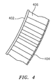
- the inner fixed structure section 332 is a one-piece honeycomb sandwich comprising an inner skin, an outer skin and a cellular core between the inner and outer skins, all bonded together.
- the honeycomb sandwich is typically an acoustic structure with an imperforate annular inner skin 402, a perforated annular outer skin 404, and a cellular core 406 suitable for use in acoustic applications.
- the inner skin 402 may be formed from a metallic or a graphite composite material (e.g., carbon fiber); the outer skin may also be formed from a metallic or graphite composite material; and the cellular core 406 may be formed from a graphite composite material.
- the inner fixed structure section 332 has an upper bifurcation wall portion 342, a lower bifurcation wall portion 344 and inner acoustic barrel portion 346 formed between the two wall portions 342, 344.
- the honeycomb sandwich is acoustic wherever possible to control noise, but is interrupted by a number of structures and formations such as cooling holes 348, the bumpers 340, the latches 338, mounting members and the like.
- the diameter of the inner acoustic barrel portion 346 increases to form an enlarged barrel portion 350 of suitable size and shape to enclose the rear engine mounts and the turbine section of the engine.
- the inner acoustic barrel portion 346 then decreases in diameter to wrap around the forward portion of the exhaust nozzle 106 ( FIG. 2 ).
- acoustic treatment [area] is at the corner joints between the barrel 346 and the bifurcations 342, 344. This is generally achieved by using a high density core to form the corner piece.
- the high density core cannot be formed to a tight radius, nor is it suitable for acoustic treatment (the cells are too close together). Consequently, a lot of potential acoustic area is lost, as shown in FIG. 5 .
- GR-EP graphite-epoxy
- a high density core is placed in the corner with doubler plies added to both skins in this zone to assure structural integrity in this highly loaded area.
- the core density and the doubler plies render this construction not suitable for acoustic treatment.
- the graphite-epoxy high density core must be thermally protected against high engine core temperatures and thus IFSs normally require insulation blankets.
- a thrust reverser inner fixed structure comprises an acoustic inner barrel, a first bifurcation panel that includes a bifurcation panel honeycomb core disposed between panel inner and outer skins, and a corner fitting, wherein the corner fitting is liquid interface diffusion (LID) bonded to the acoustic inner barrel and the first bifurcation panel.
- LID liquid interface diffusion
- a thrust reverser inner fixed structure comprises an acoustic inner barrel that comprises a barrel honeycomb core having an annular interior skin radially inward of the first honeycomb core, a first bifurcation panel, and a corner fitting, wherein the corner fitting is LID bonded to the acoustic inner barrel and the first bifurcation panel.
- a thrust reverser inner fixed structure comprises an acoustic inner barrel that includes a barrel honeycomb core having an annular interior skin radially inward of the first honeycomb core, a first bifurcation panel that includes a bifurcation panel honeycomb core disposed between panel inner and outer skins, and a corner fitting, wherein the corner fitting is LID bonded to the acoustic inner barrel and the first bifurcation panel.
- a method for providing a thrust reverser inner fixed structure.
- the method includes (a) providing an acoustic inner barrel that includes a first honeycomb core and an annular inner skin radially inward of the first honeycomb core; (b) providing a bifurcation panel that includes a second honeycomb core; and (c) arranging a corner fitting between and attaching the corner fitting to the acoustic inner barrel and the bifurcation panel.
- another method for providing a thrust reverser inner fixed structure.
- the method includes (a) forming an acoustic inner barrel that includes a first honeycomb core; (b) forming a bifurcation panel that includes a second honeycomb core; (c) forming a corner fitting independent of the acoustic inner barrel and the bifurcation panel; and (d) connecting the acoustic inner barrel to the bifurcation panel with the corner fitting.
- the corner fitting may be titanium.
- the barrel honeycomb core may also or alternatively include a titanium annular inner skin and/or a titanium honeycomb acoustic core.
- the bifurcation panel may also or alternatively include a titanium skin and/or a titanium honeycomb acoustic core.
- the titanium honeycomb core may be formed, for example, by super plastic formation (SPF) processing or 360° SPF processing.
- SPF super plastic formation
- 360° SPF processing 360° SPF processing.
- the corner fitting may include a first set of flanges that form a first channel, and/or a second set of flanges that form a second channel.
- An end surface/face skin of the bifurcation panel may be LID bonded or otherwise attached to the first set of flanges, and the end surface/face skin of the barrel may be LID bonded or otherwise attached to the second set of flanges.
- the corner fitting may be attached to the acoustic inner barrel and/or the bifurcation panel by liquid interface diffusion (LID) bonding.
- the corner fitting may also or alternatively be attached to the acoustic inner barrel and/or the bifurcation panel by an adhesive.
- the corner fitting may also or alternatively be attached to the acoustic inner barrel and/or the bifurcation panel by one or more mechanical fasteners.
- a portion of the corner fitting may be inserted into a channel in the acoustic inner barrel.
- a portion of the corner fitting may also or alternatively be inserted into a channel in the bifurcation panel.
- a portion of the acoustic inner barrel may also or alternatively be inserted into a channel in the corner fitting.
- a portion of the bifurcation panel may also or alternatively be inserted into a channel in the corner fitting.
- the corner fitting may be formed discretely from the acoustic inner barrel and/or the bifurcation panel.
- the corner fitting may be formed by one or more of the following processes: casting and/or machining.
- FIG. 6 illustrates a thrust reverser inner fixed structure component 600 comprising an acoustic inner barrel 602 that includes a barrel honeycomb core 604, a first bifurcation panel 606 that includes a bifurcation panel honeycomb core 608, and a corner fitting 610.
- This corner fitting 610 is attached to the barrel 602 and/or the first bifurcation panel 606.
- the corner fitting 610 may be liquid interface diffusion (LID) bonded and/or otherwise attached to the barrel 602 and the first bifurcation panel 606.
- LID bonding combines the attributes of brazing and diffusion bonding to attain near-base metal properties in a bonded sandwich panel. The result is a lightweight component that can stand up to harsh exhaust environments.
- the barrel honeycomb core 604, the bifurcation panel honeycomb core 608 or both the barrel honeycomb core 604 and the bifurcation panel honeycomb core 608 may each be discretely formed from titanium.
- the barrel 602 may include one or more titanium skins and a titanium honeycomb acoustic core (or equivalent material) between the skins, so as not to require thermal insulation to protect the structure.
- the bifurcation panel 606 may be of a similar construction or of dissimilar materials (such as GR-EP) and/or constructions, if they are suitably isolated or insulated from engine core heat.
- FIG. 7 is a pictorial illustration of the corner fitting 610.
- the corner fitting 610 is preferably a titanium component that may, for example, be a machined casting or machined.
- the corner fitting 610 includes a web 612 and a plurality of flanges 613-616 that form first and second channels 618, 620.
- FIG. 8 is an isometric view of the embodiment of the corner fitting 610, along with a cross sectional illustration of the embodiment of the corner fitting 610.
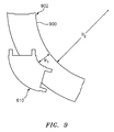
- FIG. 9 is a side sectional illustration of the corner fitting 610 overlaid on a curved portion 900 of an acoustic sandwich panel 902. Since the corner fitting 610 may be cast and/or machined as described above, an inner radius R 1 of the corner fitting 610 may be (e.g., about six times) smaller than an inner radius R 2 of the curved portion 900, which is intended to represent a minimum radius the panel 902 may be bent without crushing and/or otherwise losing structural integrity of its honeycomb core. It is worth noting that a curved portion of an acoustic sandwich panel such as the portion 900 is typically ineffective for noise attenuation. However, the relatively small radius R 1 of the corner fitting 610 enables the acoustic inner barrel 602 and/or the bifurcation panel 606 (see FIG. 6 ) to be enlarged, which may increase their effective area for noise attenuation.
- an inner radius R 1 of the corner fitting 610 may be (e.g., about six times) smaller than an inner radius
- the bifurcation panel 606 is mated and attached to the corner fitting 610.
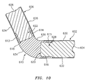
- An end portion 622 of the core 608 of FIG. 10 is inserted into the channel 618.
- First and/or second skins 624 and 626 of the bifurcation panel 606 are respectively LID bonded to the flanges 613 and 614.
- the first and/or the second skins 624 and 626 may also or alternatively be bonded to the flanges 613 and 614 using one or more techniques other than LID bonding such as, for example, welding, brazing and/or adhering with an adhesive (e.g., epoxy).
- the first and/or the second skins 624 and 626 may also or alternatively be mechanically attached to the flanges 613 and 614 using one or more rivets, screws, bolts or any other type of mechanical fasteners.
- the acoustic inner barrel 602 is also mated and attached to the corner fitting 610.
- An end portion 628 of the core 604 of FIG. 10 is inserted into the channel 620.
- First and/or second skins 630 and 632 of the barrel 602 are respectively LID bonded to the flanges 615 and 616.
- the first and/or the second skins 630 and 632 may also or alternatively be bonded to the flanges 615 and 616 using one or more techniques other than LID bonding such as, for example, welding, brazing and/or adhering with an adhesive (e.g., epoxy).
- the first and/or the second skins 630 and 632 may also or alternatively be mechanically attached to the flanges 615 and 616 using one or more rivets, screws, bolts or any other type of mechanical fasteners.
- a portion 634 of a surface of the corner fitting 610 between the skins 624 and 632 is left exposed.
- a portion 636 of an opposite surface of the corner fitting 610 between the skins 626 and 630 is also left exposed.
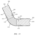
- the acoustic inner barrel 602 and bifurcation panel 606 may share one or more skins 638 and 640. Each of these shared skins 638 and 640 respectively overlaps and is attached to the corner fitting 610. In this manner, the corner fitting 610 provides a structural core at the corner joint between the barrel 602 and the panel 606.
- FIG. 12 illustrates an alternate embodiment corner fitting 610' for connecting the acoustic inner barrel 602 to the bifurcation panel 606.
- the corner fitting 610' is configured having a plurality of recesses 642-645 rather than the flanges 613-616.
- the skins 624, 626 and 630, 632 which may form the channels 650 and 652, respectively overlap the end portions 646 and 648 and are seated within the recesses 642-645.
- One or more of the skins 624, 626, 630 and 632 are respectively attached (e.g., LID bonded) to the end portions 646 and 648 and/or a central portion 654 of the corner fitting 610'.
- FIG. 13 is a pictorial illustration of the honeycomb core 604 of the acoustic inner barrel 602, and the corner fitting 610.
- the honeycomb core may be formed from titanium.
- FIG. 14 is a pictorial illustration of annular inner skin 612 of the acoustic inner barrel covering the honeycomb core 604, and the barrel joined to the corner fitting 610.
- One titanium manufacturing option is the use of 360° SPF process, which enables the forming of axis symmetric-skins. These may then be LID bonded into core cowl structures. Cowls would subsequently be trimmed into two or three high temperature sections to contain engine core heat. A primary advantage will be that this allows the now thermally isolated bifurcation structures to be manufactured of lighter/ cheaper materials.
- a thrust reverser inner fixed structure component provides a blanket-less IFS structure that can withstand elevated engine core temperatures without the need for an insulating blanket.
- titanium is a preferred metal for the corner fitting, the first honeycomb core and the annular skins of the acoustic inner barrel, as well as the honeycomb core of the bifurcation panel and its annular skins, it is contemplated that one or more of these elements may be formed from metals such as, for example, aluminum or inconel. If aluminum is used, then an insulting blanket may be provided to protect against elevated engine core temperatures. It is also contemplated that one or more of the skins and/or other elements may be formed from a composite material such as carbon fiber.
- the barrel 602 and the corner fitting 610 may be formed from metal and LID bonded together, whereas one or more of the bifurcation panel skins may be formed from a composite and adhered and/or mechanically attached to the corner fitting 610, or vice versa.
- the corner fitting and the acoustic inner barrel may interface in the manner shown in FIG. 10 whereas the corner fitting and the bifurcation panel may interface in the manner shown in FIG. 12 , or vice versa.
- one or more of the skins may be attached to the corner fitting in a different manner than one or more of the skins. Accordingly, the present invention is not to be restricted except in light of the associated claims and their equivalents.
Landscapes
- Engineering & Computer Science (AREA)
- Mechanical Engineering (AREA)
- Chemical & Material Sciences (AREA)
- Combustion & Propulsion (AREA)
- General Engineering & Computer Science (AREA)
- Aviation & Aerospace Engineering (AREA)
- Body Structure For Vehicles (AREA)
- Sliding-Contact Bearings (AREA)
Abstract
Description
- The invention relates to the field of protective systems for aircraft propulsion system components and in particular, to a liquid interface diffusion (LID) bonded titanium inner fixed structure (IFS) with bonded-in corner fitting for an aircraft engine nacelle system.
- A nacelle system is the aerodynamic structure that surrounds an aircraft engine. It includes parts commonly referred to as engine cowling, but the nacelle system typically includes other components as well including the inlet cowl, fan cowl, thrust reverser, core cowl and nozzle.
-
FIG. 1 illustrates an assembled, completeaircraft propulsion assembly 100, andFIG. 2 shows an exploded view of theaircraft propulsion assembly 100 ofFIG. 1 . Referring toFIGs. 1 and2 , components of the aircraft propulsion system include anengine assembly 102 at the tail end of which are anexhaust cone 104 and anexhaust nozzle 106. The forward end of theengine assembly 102 includes anacelle inlet 110 having anacelle inlet lip 112. Aft of thenacelle inlet 110 is afan cowl 120 comprisingfan cowl halves thrust reverser 130 comprisingthrust reverser halves fan cowl 120. A pylon/strut assembly 140 connects the aforementioned component to a wing of an aircraft. Thethrust reverser 130 includes an outer fixed structure, a translating sleeve, and an inner fixed structure as shown inFIG. 3 . -
FIG. 3 shows thrust reverserhalf 330 which exposes a onehalf section 332 of an inner fixed structure (IFS) formed in two "clam-shell" halves, only one clam-shell half being shown. It is understood that the unseen second section is essentially a mirror image of thesection 332. The IFS section has a forward end 334 with anexterior surface 335 that faces in the direction of the engine and fan cowl, and anaft end 336 with an exterior surface (not shown) that faces in the direction of the exhaust nozzle. TheIFS halves 332 are connected together bylatches 338 at the bottom and hinged to the pylon 140 (FIG. 2 ) at the top.Bumpers 340 provide a structural bridge between the gaps that separates the twoIFS halves 332. The structural bridge provides a hoop load path to resist the crushing pressure of the fan air stream upon the barrel sections and bifurcations. - The inner fixed structure illustrated in
FIG. 3 encases portions of the engine assembly located between the engine fan case and the nozzle. The inner fixed structure is configured to create an aerodynamically smooth path for air, and a fire and heat boundary by enclosing portions of the engine assembly. - The inner
fixed structure section 332 is a one-piece honeycomb sandwich comprising an inner skin, an outer skin and a cellular core between the inner and outer skins, all bonded together. Referring toFIG. 4 , the honeycomb sandwich is typically an acoustic structure with an imperforate annularinner skin 402, a perforated annularouter skin 404, and acellular core 406 suitable for use in acoustic applications. Theinner skin 402 may be formed from a metallic or a graphite composite material (e.g., carbon fiber); the outer skin may also be formed from a metallic or graphite composite material; and thecellular core 406 may be formed from a graphite composite material. - Referring again to
FIG. 3 , the innerfixed structure section 332 has an upperbifurcation wall portion 342, a lowerbifurcation wall portion 344 and inneracoustic barrel portion 346 formed between the twowall portions cooling holes 348, thebumpers 340, thelatches 338, mounting members and the like. - Aft of its forward end where it interfaces with the fan section, the diameter of the inner
acoustic barrel portion 346 increases to form an enlargedbarrel portion 350 of suitable size and shape to enclose the rear engine mounts and the turbine section of the engine. The inneracoustic barrel portion 346 then decreases in diameter to wrap around the forward portion of the exhaust nozzle 106 (FIG. 2 ). - Acoustic treatment of an inner fixed structure is always at a premium because of the large number of openings and attachments.
- One potential opportunity for increasing acoustic treatment [area] is at the corner joints between the
barrel 346 and thebifurcations FIG. 5 . - In conventional inner fixed structures with graphite-epoxy (GR-EP) skins, a high density core is placed in the corner with doubler plies added to both skins in this zone to assure structural integrity in this highly loaded area. The core density and the doubler plies render this construction not suitable for acoustic treatment. In addition, the graphite-epoxy high density core must be thermally protected against high engine core temperatures and thus IFSs normally require insulation blankets.
- There is a need for an inner fixed structure which increases the acoustic treatment for noise suppression in comers/joints of the inner fixed structure between the barrel and the bifurcations.
- According to an aspect of the invention, a thrust reverser inner fixed structure comprises an acoustic inner barrel, a first bifurcation panel that includes a bifurcation panel honeycomb core disposed between panel inner and outer skins, and a corner fitting, wherein the corner fitting is liquid interface diffusion (LID) bonded to the acoustic inner barrel and the first bifurcation panel.
- According to another aspect of the invention, a thrust reverser inner fixed structure comprises an acoustic inner barrel that comprises a barrel honeycomb core having an annular interior skin radially inward of the first honeycomb core, a first bifurcation panel, and a corner fitting, wherein the corner fitting is LID bonded to the acoustic inner barrel and the first bifurcation panel.
- According to another aspect of the invention, a thrust reverser inner fixed structure comprises an acoustic inner barrel that includes a barrel honeycomb core having an annular interior skin radially inward of the first honeycomb core, a first bifurcation panel that includes a bifurcation panel honeycomb core disposed between panel inner and outer skins, and a corner fitting, wherein the corner fitting is LID bonded to the acoustic inner barrel and the first bifurcation panel.
- According to another aspect of the invention, a method is provided for providing a thrust reverser inner fixed structure. The method includes (a) providing an acoustic inner barrel that includes a first honeycomb core and an annular inner skin radially inward of the first honeycomb core; (b) providing a bifurcation panel that includes a second honeycomb core; and (c) arranging a corner fitting between and attaching the corner fitting to the acoustic inner barrel and the bifurcation panel.
- According to a further aspect of the invention, another method is provided for providing a thrust reverser inner fixed structure. The method includes (a) forming an acoustic inner barrel that includes a first honeycomb core; (b) forming a bifurcation panel that includes a second honeycomb core; (c) forming a corner fitting independent of the acoustic inner barrel and the bifurcation panel; and (d) connecting the acoustic inner barrel to the bifurcation panel with the corner fitting.
- In any of the above aspects or embodiments, the corner fitting may be titanium. The barrel honeycomb core may also or alternatively include a titanium annular inner skin and/or a titanium honeycomb acoustic core. The bifurcation panel may also or alternatively include a titanium skin and/or a titanium honeycomb acoustic core.
- In any of the above aspects or embodiments, the titanium honeycomb core may be formed, for example, by super plastic formation (SPF) processing or 360° SPF processing.
- In any of the above aspects or embodiments, the corner fitting may include a first set of flanges that form a first channel, and/or a second set of flanges that form a second channel. An end surface/face skin of the bifurcation panel may be LID bonded or otherwise attached to the first set of flanges, and the end surface/face skin of the barrel may be LID bonded or otherwise attached to the second set of flanges.
- In any of the above aspects or embodiments, the corner fitting may be attached to the acoustic inner barrel and/or the bifurcation panel by liquid interface diffusion (LID) bonding. The corner fitting may also or alternatively be attached to the acoustic inner barrel and/or the bifurcation panel by an adhesive. The corner fitting may also or alternatively be attached to the acoustic inner barrel and/or the bifurcation panel by one or more mechanical fasteners.
- In any of the above aspects or embodiments, a portion of the corner fitting may be inserted into a channel in the acoustic inner barrel. A portion of the corner fitting may also or alternatively be inserted into a channel in the bifurcation panel. A portion of the acoustic inner barrel may also or alternatively be inserted into a channel in the corner fitting. A portion of the bifurcation panel may also or alternatively be inserted into a channel in the corner fitting.
- In any of the above aspects or embodiments, the corner fitting may be formed discretely from the acoustic inner barrel and/or the bifurcation panel.
- In any of the above aspects or embodiments, the corner fitting may be formed by one or more of the following processes: casting and/or machining.
- The foregoing features and the operation of the invention will become more apparent in light of the following description and the accompanying drawings.
-
-
FIG. 1 illustrates an assembled, complete aircraft propulsion assembly; -
FIG. 2 shows an exploded view of the aircraft propulsion assembly; -
FIG. 3 shows a thrust reverser half which exposes a one half section of an inner fixed structure (IFS) formed in two "clam-shell" halves; -
FIG. 4 . illustrates a honeycomb sandwich comprising an inner skin, an outer skin and a cellular core between the inner and outer skin panels; -
FIG. 5 is a more detailed illustration of a prior art non-acoustic corner between the inner acoustic barrel and the bifurcation panel; -
FIG. 6 illustrates a thrust reverser inner fixed structure component comprising an acoustic inner barrel that comprises a honeycomb core, a first bifurcation panel that includes a honeycomb core, and a corner fitting, wherein the corner fitting is LID bonded to the acoustic inner barrel and the first bifurcation panel; -
FIG. 7 is a pictorial illustration of an embodiment of the corner fitting; -
FIG. 8 is an isometric view of the embodiment of the corner fitting, along with a cross sectional illustration of the embodiment of the corner fitting; -
FIG. 9 is a side sectional illustration of the corner fitting overlaid on a curved portion of an acoustic sandwich panel; -
FIG. 10 is a side sectional illustration of a corner fitting connecting an acoustic inner barrel with a bifurcation panel; -
FIG. 11 is a side sectional illustration of another corner fitting connecting an acoustic inner barrel with a bifurcation panel; -
FIG. 12 is a side sectional illustration of another corner fitting connecting an acoustic inner barrel with a bifurcation panel; -
FIG. 13 is a pictorial illustration of the barrel with the honeycomb core exposed (i.e., the annular inner skin removed), and the corner fitting; and -
FIG. 14 is a pictorial illustration of the barrel with annular inner skin of the acoustic inner barrel covering the honeycomb core, and the barrel joined to the corner fitting. -
FIG. 6 illustrates a thrust reverser inner fixedstructure component 600 comprising an acousticinner barrel 602 that includes abarrel honeycomb core 604, afirst bifurcation panel 606 that includes a bifurcationpanel honeycomb core 608, and a corner fitting 610. This corner fitting 610 is attached to thebarrel 602 and/or thefirst bifurcation panel 606. The corner fitting 610, for example, may be liquid interface diffusion (LID) bonded and/or otherwise attached to thebarrel 602 and thefirst bifurcation panel 606. LID bonding combines the attributes of brazing and diffusion bonding to attain near-base metal properties in a bonded sandwich panel. The result is a lightweight component that can stand up to harsh exhaust environments. - The
barrel honeycomb core 604, the bifurcationpanel honeycomb core 608 or both thebarrel honeycomb core 604 and the bifurcationpanel honeycomb core 608 may each be discretely formed from titanium. For example, thebarrel 602 may include one or more titanium skins and a titanium honeycomb acoustic core (or equivalent material) between the skins, so as not to require thermal insulation to protect the structure. It is contemplated that thebifurcation panel 606 may be of a similar construction or of dissimilar materials (such as GR-EP) and/or constructions, if they are suitably isolated or insulated from engine core heat. -
FIG. 7 is a pictorial illustration of the corner fitting 610. The corner fitting 610 is preferably a titanium component that may, for example, be a machined casting or machined. The corner fitting 610 includes aweb 612 and a plurality of flanges 613-616 that form first andsecond channels FIG. 8 is an isometric view of the embodiment of the corner fitting 610, along with a cross sectional illustration of the embodiment of the corner fitting 610. -
FIG. 9 is a side sectional illustration of the corner fitting 610 overlaid on acurved portion 900 of anacoustic sandwich panel 902. Since the corner fitting 610 may be cast and/or machined as described above, an inner radius R1 of the corner fitting 610 may be (e.g., about six times) smaller than an inner radius R2 of thecurved portion 900, which is intended to represent a minimum radius thepanel 902 may be bent without crushing and/or otherwise losing structural integrity of its honeycomb core. It is worth noting that a curved portion of an acoustic sandwich panel such as theportion 900 is typically ineffective for noise attenuation. However, the relatively small radius R1 of the corner fitting 610 enables the acousticinner barrel 602 and/or the bifurcation panel 606 (seeFIG. 6 ) to be enlarged, which may increase their effective area for noise attenuation. - Referring to
FIG. 10 , thebifurcation panel 606 is mated and attached to the corner fitting 610. Anend portion 622 of thecore 608 ofFIG. 10 , for example, is inserted into thechannel 618. First and/orsecond skins bifurcation panel 606 are respectively LID bonded to theflanges second skins flanges second skins flanges - The acoustic
inner barrel 602 is also mated and attached to the corner fitting 610. Anend portion 628 of thecore 604 ofFIG. 10 , for example, is inserted into thechannel 620. First and/orsecond skins barrel 602 are respectively LID bonded to theflanges second skins flanges second skins flanges - With the interface described above and illustrated in
FIG. 10 , aportion 634 of a surface of the corner fitting 610 between theskins portion 636 of an opposite surface of the corner fitting 610 between theskins FIG. 11 , the acousticinner barrel 602 andbifurcation panel 606 may share one ormore skins skins barrel 602 and thepanel 606. -
FIG. 12 illustrates an alternate embodiment corner fitting 610' for connecting the acousticinner barrel 602 to thebifurcation panel 606. In contrast to the corner fitting 610 ofFIG. 10 , the corner fitting 610' is configured having a plurality of recesses 642-645 rather than the flanges 613-616.End portions channels barrel 602 and thepanel 606. Theskins channels end portions skins end portions central portion 654 of the corner fitting 610'. -
FIG. 13 is a pictorial illustration of thehoneycomb core 604 of the acousticinner barrel 602, and the corner fitting 610. The honeycomb core may be formed from titanium. -
FIG. 14 is a pictorial illustration of annularinner skin 612 of the acoustic inner barrel covering thehoneycomb core 604, and the barrel joined to the corner fitting 610. - One titanium manufacturing option is the use of 360° SPF process, which enables the forming of axis symmetric-skins. These may then be LID bonded into core cowl structures. Cowls would subsequently be trimmed into two or three high temperature sections to contain engine core heat. A primary advantage will be that this allows the now thermally isolated bifurcation structures to be manufactured of lighter/ cheaper materials.
- A thrust reverser inner fixed structure component according to aspect of the present invention provides a blanket-less IFS structure that can withstand elevated engine core temperatures without the need for an insulating blanket.
- Although titanium is a preferred metal for the corner fitting, the first honeycomb core and the annular skins of the acoustic inner barrel, as well as the honeycomb core of the bifurcation panel and its annular skins, it is contemplated that one or more of these elements may be formed from metals such as, for example, aluminum or inconel. If aluminum is used, then an insulting blanket may be provided to protect against elevated engine core temperatures. It is also contemplated that one or more of the skins and/or other elements may be formed from a composite material such as carbon fiber. For example, the
barrel 602 and the corner fitting 610 may be formed from metal and LID bonded together, whereas one or more of the bifurcation panel skins may be formed from a composite and adhered and/or mechanically attached to the corner fitting 610, or vice versa. - While various embodiments of the present invention have been disclosed, it will be apparent to those of ordinary skill in the art that many more embodiments and implementations are possible within the scope of the invention. For example, the corner fitting and the acoustic inner barrel may interface in the manner shown in
FIG. 10 whereas the corner fitting and the bifurcation panel may interface in the manner shown inFIG. 12 , or vice versa. In another example, one or more of the skins may be attached to the corner fitting in a different manner than one or more of the skins. Accordingly, the present invention is not to be restricted except in light of the associated claims and their equivalents.
Claims (15)
- A method for providing a thrust reverser inner fixed structure (600), the method comprising:providing an acoustic inner barrel (602) that includes a first honeycomb core (604) and an annular inner skin (630) radially inward of the first honeycomb core (604);providing a bifurcation panel (606) that includes a second honeycomb core (608); andarranging a corner fitting (610, 610') between and attaching the corner fitting (610, 610') to the acoustic inner barrel (602) and the bifurcation panel (606).
- The method of claim 1, wherein the corner fitting (610, 610') is attached to the acoustic inner barrel (602) and/or the bifurcation panel (606) by liquid interface diffusion (LID) bonding.
- The method of claim 1 or 2, wherein the corner fitting (610, 610') is attached to the acoustic inner barrel (602) and/or the bifurcation panel (606) by an adhesive.
- The method of any of claims 1 to 3, wherein the corner fitting (610, 610') is attached to the acoustic inner barrel (602) and/or the bifurcation panel (606) by one or more mechanical fasteners.
- The method of any preceding claim, wherein the annular inner skin (630) comprises titanium.
- The method of any preceding claim, wherein the first honeycomb core (604) comprises titanium.
- The method of any of claims 1 to 5, wherein the second honeycomb core (608) comprises titanium.
- The method of any of claims 1 to 4, wherein the first honeycomb core (604) and the second honeycomb core (608) each comprises titanium.
- The method of any preceding claim, wherein the annular inner skin (630), the first honeycomb core (604) and the second honeycomb core (608) each comprises titanium.
- The method of any preceding claim, further comprising inserting a portion (646, 648) of the corner fitting (610') into a channel (646, 648) in the acoustic inner barrel (602) or the bifurcation panel (606).
- The method of any of claims 1 to 9, further comprising inserting a portion (628) of the acoustic inner barrel (602) into a channel (620) in the corner fitting (610).
- The method of any of claims 1 to 9 or 11, further comprising inserting a portion (622) of the bifurcation panel (606) into a channel (618) in the corner fitting (610).
- The method of any preceding claim, further comprising forming the corner fitting (610, 610') discretely from the acoustic inner barrel (602) and the bifurcation panel (606).
- The method of any preceding claim, further comprising forming the corner fitting (610, 610') using casting and/or machining.
- A method for providing a thrust reverser inner fixed structure (600), the method comprising:forming an acoustic inner barrel (602) that includes a first honeycomb core (604);forming a bifurcation panel (606) that includes a second honeycomb core (608);forming a corner fitting (610, 610') independent of the acoustic inner barrel (602) and the bifurcation panel (606); andconnecting the acoustic inner barrel (602) to the bifurcation panel (606) with the corn$er fitting (610, 610').
Applications Claiming Priority (2)
| Application Number | Priority Date | Filing Date | Title |
|---|---|---|---|
| US201361803048P | 2013-03-18 | 2013-03-18 | |
| US14/056,695 US20150041059A1 (en) | 2013-03-18 | 2013-10-17 | Inner fixed structure with attached corner fitting |
Publications (2)
| Publication Number | Publication Date |
|---|---|
| EP2781728A2 true EP2781728A2 (en) | 2014-09-24 |
| EP2781728A3 EP2781728A3 (en) | 2017-10-11 |
Family
ID=50343590
Family Applications (1)
| Application Number | Title | Priority Date | Filing Date |
|---|---|---|---|
| EP14159512.4A Withdrawn EP2781728A3 (en) | 2013-03-18 | 2014-03-13 | Thrust reverser inner fixed structure with corner fitting |
Country Status (2)
| Country | Link |
|---|---|
| US (1) | US20150041059A1 (en) |
| EP (1) | EP2781728A3 (en) |
Cited By (5)
| Publication number | Priority date | Publication date | Assignee | Title |
|---|---|---|---|---|
| GB2570913A (en) * | 2018-02-09 | 2019-08-14 | Safran Nacelles Ltd | Inner fixed structure |
| US10507931B2 (en) * | 2015-10-19 | 2019-12-17 | Rohr, Inc. | Panel and insert for corner radii |
| FR3100570A1 (en) * | 2019-09-09 | 2021-03-12 | Safran Nacelles | Structural and / or acoustic panel comprising a U-shaped closing flange oriented towards the interior of the panel, and method of manufacturing such a panel |
| EP3055541B1 (en) * | 2013-10-07 | 2021-12-08 | Rohr, Inc. | Hybrid inner fixed structure with metallic and composite construction |
| US11535390B2 (en) | 2020-02-28 | 2022-12-27 | Rohr, Inc. | Structural panel with integrated coupler |
Families Citing this family (8)
| Publication number | Priority date | Publication date | Assignee | Title |
|---|---|---|---|---|
| US20150267644A1 (en) * | 2014-03-19 | 2015-09-24 | The Boeing Company | Integrated Primary Nozzle |
| US9623977B2 (en) * | 2014-03-20 | 2017-04-18 | The Boeing Company | Hybrid structure including built-up sandwich structure and monolithic SPF/DB structure |
| US9499275B2 (en) * | 2014-10-16 | 2016-11-22 | Rohr, Inc. | Stress-relieving joint between materials with differing coefficients of thermal expansion |
| US10253727B2 (en) * | 2016-05-12 | 2019-04-09 | Rohr, Inc. | Backside acoustic treatment of nacelle structural fittings |
| US10161357B2 (en) * | 2016-06-17 | 2018-12-25 | Rohr, Inc. | Acoustically treated thrust reverser track beam |
| US11925971B2 (en) | 2021-09-10 | 2024-03-12 | Rohr, Inc. | Component with structured panel(s) and methods for forming the component |
| US11780021B2 (en) * | 2021-09-10 | 2023-10-10 | Rohr, Inc. | Component with structured panel(s) and methods for forming the component |
| FR3148007A1 (en) * | 2023-04-24 | 2024-10-25 | Airbus Operations | FIXED INTERNAL STRUCTURE FOR AN AIRCRAFT NACELLE |
Family Cites Families (10)
| Publication number | Priority date | Publication date | Assignee | Title |
|---|---|---|---|---|
| US3572971A (en) * | 1969-09-29 | 1971-03-30 | Gen Electric | Lightweight turbo-machinery blading |
| US4283028A (en) * | 1979-12-03 | 1981-08-11 | The Boeing Company | Adjustable wedge fitting for sharing the thrust load of a jet engine |
| US5101621A (en) * | 1989-09-25 | 1992-04-07 | Rohr Industries, Inc. | Integrated corner for ducted fan engine shrouds |
| US5083426A (en) * | 1989-10-02 | 1992-01-28 | Rohr Industries, Inc. | Integrated engine shroud for gas turbine engines |
| US6871725B2 (en) * | 2003-02-21 | 2005-03-29 | Jeffrey Don Johnson | Honeycomb core acoustic unit with metallurgically secured deformable septum, and method of manufacture |
| WO2005098241A1 (en) * | 2004-03-31 | 2005-10-20 | Remmele Engineering, Inc. | Connection mechanism and method |
| US20100043955A1 (en) * | 2008-08-21 | 2010-02-25 | Hornick David C | Flat-Cured Composite Structure |
| US8197191B2 (en) * | 2009-04-14 | 2012-06-12 | Rohr, Inc. | Inlet section of an aircraft engine nacelle |
| US7854594B2 (en) * | 2009-04-28 | 2010-12-21 | General Electric Company | Segmented wind turbine blade |
| US9168716B2 (en) * | 2012-09-14 | 2015-10-27 | The Boeing Company | Metallic sandwich structure having small bend radius |
-
2013
- 2013-10-17 US US14/056,695 patent/US20150041059A1/en not_active Abandoned
-
2014
- 2014-03-13 EP EP14159512.4A patent/EP2781728A3/en not_active Withdrawn
Non-Patent Citations (1)
| Title |
|---|
| None |
Cited By (9)
| Publication number | Priority date | Publication date | Assignee | Title |
|---|---|---|---|---|
| EP3055541B1 (en) * | 2013-10-07 | 2021-12-08 | Rohr, Inc. | Hybrid inner fixed structure with metallic and composite construction |
| US10507931B2 (en) * | 2015-10-19 | 2019-12-17 | Rohr, Inc. | Panel and insert for corner radii |
| GB2570913A (en) * | 2018-02-09 | 2019-08-14 | Safran Nacelles Ltd | Inner fixed structure |
| WO2019155015A1 (en) * | 2018-02-09 | 2019-08-15 | Safran Nacelles Limited | Thrust reverser inner fixed structure |
| FR3100570A1 (en) * | 2019-09-09 | 2021-03-12 | Safran Nacelles | Structural and / or acoustic panel comprising a U-shaped closing flange oriented towards the interior of the panel, and method of manufacturing such a panel |
| WO2021048489A1 (en) * | 2019-09-09 | 2021-03-18 | Safran Nacelles | Structural and/or acoustic panel comprising a u-shaped sealing flange directed toward the inside of the panel, and method for manufacturing such a panel |
| CN114502827A (en) * | 2019-09-09 | 2022-05-13 | 赛峰短舱公司 | Structural and/or acoustic panel comprising a U-shaped sealing flange oriented towards the inside of the panel, and method for manufacturing such a panel |
| US12065988B2 (en) | 2019-09-09 | 2024-08-20 | Safran Nacelles | Structural and/or acoustic panel comprising a u-shaped sealing flange directed toward the inside of the panel, and method for manufacturing such a panel |
| US11535390B2 (en) | 2020-02-28 | 2022-12-27 | Rohr, Inc. | Structural panel with integrated coupler |
Also Published As
| Publication number | Publication date |
|---|---|
| US20150041059A1 (en) | 2015-02-12 |
| EP2781728A3 (en) | 2017-10-11 |
Similar Documents
| Publication | Publication Date | Title |
|---|---|---|
| EP2781728A2 (en) | Thrust reverser inner fixed structure with corner fitting | |
| US9051899B2 (en) | Exhaust cone for aircraft turbojet engine | |
| RU2541369C2 (en) | Jet nozzle bearer, jet nozzle and jet nozzle pod | |
| US9168716B2 (en) | Metallic sandwich structure having small bend radius | |
| EP3055541B1 (en) | Hybrid inner fixed structure with metallic and composite construction | |
| EP3489947B1 (en) | Acoustic panel with structural septum | |
| US8523516B2 (en) | Bypass turbojet engine nacelle | |
| US9897007B2 (en) | Thrust reverser-integrated track beam and inner fixed structure | |
| EP2255086B1 (en) | Stave and ring cmc nozzle | |
| US9016042B2 (en) | Reinforcement members for aircraft propulsion system components configured to address delamination of the inner fixed structure | |
| US20120308379A1 (en) | Aircraft engine cowl and process therefor | |
| EP3871979B1 (en) | Structural panel with integrated coupler | |
| US9714627B2 (en) | Mounting of aircraft propulsion system outer sleeve and inner structure to pylon with distinct hinges | |
| US11396366B2 (en) | Active laminar flow control structural plenums fastened | |
| US20150108247A1 (en) | Inverted track beam attachment flange | |
| EP3628596B1 (en) | Active laminar flow control plenum panel arrangements and installation methods | |
| US9951652B2 (en) | Aircraft thrust reversing assembly IFS support structure | |
| US10161357B2 (en) | Acoustically treated thrust reverser track beam | |
| CN116713473A (en) | Metal structures and manufacturing methods for additively manufactured metal articles |
Legal Events
| Date | Code | Title | Description |
|---|---|---|---|
| PUAI | Public reference made under article 153(3) epc to a published international application that has entered the european phase |
Free format text: ORIGINAL CODE: 0009012 |
|
| 17P | Request for examination filed |
Effective date: 20140313 |
|
| AK | Designated contracting states |
Kind code of ref document: A2 Designated state(s): AL AT BE BG CH CY CZ DE DK EE ES FI FR GB GR HR HU IE IS IT LI LT LU LV MC MK MT NL NO PL PT RO RS SE SI SK SM TR |
|
| AX | Request for extension of the european patent |
Extension state: BA ME |
|
| PUAL | Search report despatched |
Free format text: ORIGINAL CODE: 0009013 |
|
| AK | Designated contracting states |
Kind code of ref document: A3 Designated state(s): AL AT BE BG CH CY CZ DE DK EE ES FI FR GB GR HR HU IE IS IT LI LT LU LV MC MK MT NL NO PL PT RO RS SE SI SK SM TR |
|
| AX | Request for extension of the european patent |
Extension state: BA ME |
|
| RIC1 | Information provided on ipc code assigned before grant |
Ipc: B32B 37/00 20060101ALI20170905BHEP Ipc: B32B 37/12 20060101ALI20170905BHEP Ipc: F02K 1/70 20060101ALI20170905BHEP Ipc: F02K 1/82 20060101ALI20170905BHEP Ipc: F02K 1/56 20060101AFI20170905BHEP Ipc: B23K 1/00 20060101ALI20170905BHEP |
|
| STAA | Information on the status of an ep patent application or granted ep patent |
Free format text: STATUS: REQUEST FOR EXAMINATION WAS MADE |
|
| R17P | Request for examination filed (corrected) |
Effective date: 20180411 |
|
| RBV | Designated contracting states (corrected) |
Designated state(s): AL AT BE BG CH CY CZ DE DK EE ES FI FR GB GR HR HU IE IS IT LI LT LU LV MC MK MT NL NO PL PT RO RS SE SI SK SM TR |
|
| STAA | Information on the status of an ep patent application or granted ep patent |
Free format text: STATUS: EXAMINATION IS IN PROGRESS |
|
| 17Q | First examination report despatched |
Effective date: 20190104 |
|
| STAA | Information on the status of an ep patent application or granted ep patent |
Free format text: STATUS: THE APPLICATION HAS BEEN WITHDRAWN |
|
| 18W | Application withdrawn |
Effective date: 20201029 |