EP2781661A2 - Traveling control device for wheeled work vehicle - Google Patents
Traveling control device for wheeled work vehicle Download PDFInfo
- Publication number
- EP2781661A2 EP2781661A2 EP14161061.8A EP14161061A EP2781661A2 EP 2781661 A2 EP2781661 A2 EP 2781661A2 EP 14161061 A EP14161061 A EP 14161061A EP 2781661 A2 EP2781661 A2 EP 2781661A2
- Authority
- EP
- European Patent Office
- Prior art keywords
- traveling
- work
- pressure
- control valve
- valve
- Prior art date
- Legal status (The legal status is an assumption and is not a legal conclusion. Google has not performed a legal analysis and makes no representation as to the accuracy of the status listed.)
- Granted
Links
Images




Classifications
-
- E—FIXED CONSTRUCTIONS
- E02—HYDRAULIC ENGINEERING; FOUNDATIONS; SOIL SHIFTING
- E02F—DREDGING; SOIL-SHIFTING
- E02F9/00—Component parts of dredgers or soil-shifting machines, not restricted to one of the kinds covered by groups E02F3/00 - E02F7/00
- E02F9/20—Drives; Control devices
- E02F9/22—Hydraulic or pneumatic drives
- E02F9/2221—Control of flow rate; Load sensing arrangements
- E02F9/2225—Control of flow rate; Load sensing arrangements using pressure-compensating valves
- E02F9/2228—Control of flow rate; Load sensing arrangements using pressure-compensating valves including an electronic controller
-
- E—FIXED CONSTRUCTIONS
- E02—HYDRAULIC ENGINEERING; FOUNDATIONS; SOIL SHIFTING
- E02F—DREDGING; SOIL-SHIFTING
- E02F9/00—Component parts of dredgers or soil-shifting machines, not restricted to one of the kinds covered by groups E02F3/00 - E02F7/00
- E02F9/20—Drives; Control devices
-
- E—FIXED CONSTRUCTIONS
- E02—HYDRAULIC ENGINEERING; FOUNDATIONS; SOIL SHIFTING
- E02F—DREDGING; SOIL-SHIFTING
- E02F9/00—Component parts of dredgers or soil-shifting machines, not restricted to one of the kinds covered by groups E02F3/00 - E02F7/00
- E02F9/20—Drives; Control devices
- E02F9/22—Hydraulic or pneumatic drives
- E02F9/2253—Controlling the travelling speed of vehicles, e.g. adjusting travelling speed according to implement loads, control of hydrostatic transmission
-
- E—FIXED CONSTRUCTIONS
- E02—HYDRAULIC ENGINEERING; FOUNDATIONS; SOIL SHIFTING
- E02F—DREDGING; SOIL-SHIFTING
- E02F9/00—Component parts of dredgers or soil-shifting machines, not restricted to one of the kinds covered by groups E02F3/00 - E02F7/00
- E02F9/20—Drives; Control devices
- E02F9/22—Hydraulic or pneumatic drives
- E02F9/2278—Hydraulic circuits
- E02F9/2282—Systems using center bypass type changeover valves
-
- E—FIXED CONSTRUCTIONS
- E02—HYDRAULIC ENGINEERING; FOUNDATIONS; SOIL SHIFTING
- E02F—DREDGING; SOIL-SHIFTING
- E02F9/00—Component parts of dredgers or soil-shifting machines, not restricted to one of the kinds covered by groups E02F3/00 - E02F7/00
- E02F9/20—Drives; Control devices
- E02F9/22—Hydraulic or pneumatic drives
- E02F9/2278—Hydraulic circuits
- E02F9/2285—Pilot-operated systems
-
- E—FIXED CONSTRUCTIONS
- E02—HYDRAULIC ENGINEERING; FOUNDATIONS; SOIL SHIFTING
- E02F—DREDGING; SOIL-SHIFTING
- E02F9/00—Component parts of dredgers or soil-shifting machines, not restricted to one of the kinds covered by groups E02F3/00 - E02F7/00
- E02F9/20—Drives; Control devices
- E02F9/22—Hydraulic or pneumatic drives
- E02F9/2278—Hydraulic circuits
- E02F9/2296—Systems with a variable displacement pump
-
- F—MECHANICAL ENGINEERING; LIGHTING; HEATING; WEAPONS; BLASTING
- F15—FLUID-PRESSURE ACTUATORS; HYDRAULICS OR PNEUMATICS IN GENERAL
- F15B—SYSTEMS ACTING BY MEANS OF FLUIDS IN GENERAL; FLUID-PRESSURE ACTUATORS, e.g. SERVOMOTORS; DETAILS OF FLUID-PRESSURE SYSTEMS, NOT OTHERWISE PROVIDED FOR
- F15B11/00—Servomotor systems without provision for follow-up action ; Circuits therefor
- F15B11/02—Systems essentially incorporating special features for controlling the speed or the actuating force of an output member
- F15B11/04—Systems essentially incorporating special features for controlling the speed or the actuating force of an output member for controlling the speed
- F15B11/044—Systems essentially incorporating special features for controlling the speed or the actuating force of an output member for controlling the speed by means in the return line
-
- F—MECHANICAL ENGINEERING; LIGHTING; HEATING; WEAPONS; BLASTING
- F15—FLUID-PRESSURE ACTUATORS; HYDRAULICS OR PNEUMATICS IN GENERAL
- F15B—SYSTEMS ACTING BY MEANS OF FLUIDS IN GENERAL; FLUID-PRESSURE ACTUATORS, e.g. SERVOMOTORS; DETAILS OF FLUID-PRESSURE SYSTEMS, NOT OTHERWISE PROVIDED FOR
- F15B2211/00—Circuits for servomotor systems
- F15B2211/20—Fluid pressure source, e.g. accumulator or variable axial piston pump
- F15B2211/205—Systems with pumps
- F15B2211/2053—Type of pump
- F15B2211/20546—Type of pump variable capacity
-
- F—MECHANICAL ENGINEERING; LIGHTING; HEATING; WEAPONS; BLASTING
- F15—FLUID-PRESSURE ACTUATORS; HYDRAULICS OR PNEUMATICS IN GENERAL
- F15B—SYSTEMS ACTING BY MEANS OF FLUIDS IN GENERAL; FLUID-PRESSURE ACTUATORS, e.g. SERVOMOTORS; DETAILS OF FLUID-PRESSURE SYSTEMS, NOT OTHERWISE PROVIDED FOR
- F15B2211/00—Circuits for servomotor systems
- F15B2211/40—Flow control
- F15B2211/405—Flow control characterised by the type of flow control means or valve
- F15B2211/40515—Flow control characterised by the type of flow control means or valve with variable throttles or orifices
-
- F—MECHANICAL ENGINEERING; LIGHTING; HEATING; WEAPONS; BLASTING
- F15—FLUID-PRESSURE ACTUATORS; HYDRAULICS OR PNEUMATICS IN GENERAL
- F15B—SYSTEMS ACTING BY MEANS OF FLUIDS IN GENERAL; FLUID-PRESSURE ACTUATORS, e.g. SERVOMOTORS; DETAILS OF FLUID-PRESSURE SYSTEMS, NOT OTHERWISE PROVIDED FOR
- F15B2211/00—Circuits for servomotor systems
- F15B2211/40—Flow control
- F15B2211/415—Flow control characterised by the connections of the flow control means in the circuit
- F15B2211/41509—Flow control characterised by the connections of the flow control means in the circuit being connected to a pressure source and a directional control valve
-
- F—MECHANICAL ENGINEERING; LIGHTING; HEATING; WEAPONS; BLASTING
- F15—FLUID-PRESSURE ACTUATORS; HYDRAULICS OR PNEUMATICS IN GENERAL
- F15B—SYSTEMS ACTING BY MEANS OF FLUIDS IN GENERAL; FLUID-PRESSURE ACTUATORS, e.g. SERVOMOTORS; DETAILS OF FLUID-PRESSURE SYSTEMS, NOT OTHERWISE PROVIDED FOR
- F15B2211/00—Circuits for servomotor systems
- F15B2211/60—Circuit components or control therefor
- F15B2211/63—Electronic controllers
- F15B2211/6303—Electronic controllers using input signals
- F15B2211/6306—Electronic controllers using input signals representing a pressure
- F15B2211/6309—Electronic controllers using input signals representing a pressure the pressure being a pressure source supply pressure
-
- F—MECHANICAL ENGINEERING; LIGHTING; HEATING; WEAPONS; BLASTING
- F15—FLUID-PRESSURE ACTUATORS; HYDRAULICS OR PNEUMATICS IN GENERAL
- F15B—SYSTEMS ACTING BY MEANS OF FLUIDS IN GENERAL; FLUID-PRESSURE ACTUATORS, e.g. SERVOMOTORS; DETAILS OF FLUID-PRESSURE SYSTEMS, NOT OTHERWISE PROVIDED FOR
- F15B2211/00—Circuits for servomotor systems
- F15B2211/60—Circuit components or control therefor
- F15B2211/63—Electronic controllers
- F15B2211/6303—Electronic controllers using input signals
- F15B2211/6306—Electronic controllers using input signals representing a pressure
- F15B2211/6313—Electronic controllers using input signals representing a pressure the pressure being a load pressure
-
- F—MECHANICAL ENGINEERING; LIGHTING; HEATING; WEAPONS; BLASTING
- F15—FLUID-PRESSURE ACTUATORS; HYDRAULICS OR PNEUMATICS IN GENERAL
- F15B—SYSTEMS ACTING BY MEANS OF FLUIDS IN GENERAL; FLUID-PRESSURE ACTUATORS, e.g. SERVOMOTORS; DETAILS OF FLUID-PRESSURE SYSTEMS, NOT OTHERWISE PROVIDED FOR
- F15B2211/00—Circuits for servomotor systems
- F15B2211/60—Circuit components or control therefor
- F15B2211/665—Methods of control using electronic components
- F15B2211/6658—Control using different modes, e.g. four-quadrant-operation, working mode and transportation mode
-
- F—MECHANICAL ENGINEERING; LIGHTING; HEATING; WEAPONS; BLASTING
- F15—FLUID-PRESSURE ACTUATORS; HYDRAULICS OR PNEUMATICS IN GENERAL
- F15B—SYSTEMS ACTING BY MEANS OF FLUIDS IN GENERAL; FLUID-PRESSURE ACTUATORS, e.g. SERVOMOTORS; DETAILS OF FLUID-PRESSURE SYSTEMS, NOT OTHERWISE PROVIDED FOR
- F15B2211/00—Circuits for servomotor systems
- F15B2211/70—Output members, e.g. hydraulic motors or cylinders or control therefor
- F15B2211/705—Output members, e.g. hydraulic motors or cylinders or control therefor characterised by the type of output members or actuators
- F15B2211/7058—Rotary output members
-
- F—MECHANICAL ENGINEERING; LIGHTING; HEATING; WEAPONS; BLASTING
- F15—FLUID-PRESSURE ACTUATORS; HYDRAULICS OR PNEUMATICS IN GENERAL
- F15B—SYSTEMS ACTING BY MEANS OF FLUIDS IN GENERAL; FLUID-PRESSURE ACTUATORS, e.g. SERVOMOTORS; DETAILS OF FLUID-PRESSURE SYSTEMS, NOT OTHERWISE PROVIDED FOR
- F15B2211/00—Circuits for servomotor systems
- F15B2211/70—Output members, e.g. hydraulic motors or cylinders or control therefor
- F15B2211/71—Multiple output members, e.g. multiple hydraulic motors or cylinders
- F15B2211/7135—Combinations of output members of different types, e.g. single-acting cylinders with rotary motors
Definitions
- the present invention relates to a traveling control device for a wheeled work vehicle such as a wheeled hydraulic excavator.
- a wheeled hydraulic excavator is an example of a wheeled work vehicle.
- a wheeled hydraulic excavator includes a wheel type traveling superstructure equipped with four wheels, a revolving superstructure rotatably disposed upon the traveling superstructure and a front work device disposed at a substantially central position on the front side of the revolving superstructure, which includes a boom, an arm and a bucket.
- a traveling motor used to drive the traveling superstructure and hydraulic actuators used to drive the front work device are mounted at the wheeled hydraulic excavator.
- the flow of pressure oil delivered from a hydraulic pump to the traveling motor is controlled via a traveling directional control valve, whereas the flow of pressure oil delivered from the hydraulic pump to the hydraulic actuators for the front work device is controlled by a work directional control valve.
- Japanese Laid Open Patent Publication No. 2002-130003 discloses a wheel-type work vehicle in which the traveling directional control valve and the work directional control valve, both disposed on a center bypass line, are connected in parallel to the hydraulic pump.
- the drive pressure for the traveling motor (hereafter referred to as "traveling drive pressure") in a wheeled hydraulic excavator is lower than the drive pressures for the hydraulic actuators functioning as work operation drive sources. In particular, it is lower than the drive pressure for the boom cylinder.
- traveling drive pressure the drive pressure for the traveling motor
- the traveling directional control valve and the work directional control valve thereof disposed on the center bypass line and connected in parallel to the hydraulic pump is crawling (i.e., traveling at very low speed) or traveling at low speed, with a relatively low traveling drive pressure
- the output pressure at the hydraulic pump will be applied to the lower pressure-side traveling motor rather than to the high pressure-side boom cylinder.
- a traveling control device for a wheeled work vehicle comprises: a hydraulic pump driven by an engine; a traveling motor driven with pressure oil output from the hydraulic pump; a work device actuator that is driven with pressure oil from the hydraulic pump and drives a front work device; a traveling directional control valve via which a flow of pressure oil from the hydraulic pump to the traveling motor is controlled, and a work device directional control valve via which a flow of pressure oil from the hydraulic pump to the work device actuator is controlled, with the traveling directional control valve and the work device directional control valve disposed on a center bypass line at the hydraulic pump; a flow control valve disposed on an upstream side of the traveling directional control valve, that controls a flow rate of the pressure oil from the hydraulic pump to the traveling motor; a traveling operation member operated to engage the traveling motor in operation; a work operation member operated to engage the work device actuator in operation; a traveling operation quantity detection means for detecting a traveling operation quantity representing an extent of operation of the traveling operation member; a work operation quantity detection means for
- the traveling control device for a wheeled work vehicle may further comprise: a motor pressure detection means for detecting a pressure of pressure oil delivered to the traveling motor, wherein: the valve control means controls the flow control valve by factoring in the pressure detected by the motor pressure detection means.
- the valve control means deters the bucking of the wheeled work vehicle when shifting from the traveling operation-only state into the combination operation state by controlling the flow control valve so as to achieve a smaller opening area at the flow control valve than the opening area achieved at the flow control valve in the traveling operation-only state.
- the traveling control device for a wheeled work vehicle may further comprise: a condition decision-making means for determining that a flow rate restricting condition has been established when a traveling operation quantity equal to or greater than a predetermined value is detected by the traveling operation quantity detection means and a work operation quantity equal to or greater than a predetermined value is detected by the work operation quantity detection means; and an enabling/disabling means for enabling the valve control means to control the flow control valve when the condition decision-making means determines that the flow rate restricting condition has been established and disabling control of the flow control valve by the valve control means when the condition decision-making means determines that the flow rate restricting condition has not been established.
- the traveling control device for a wheeled work vehicle may further comprise: a reduction mechanism, capable of altering a reduction ratio, that slows down rotation of the traveling motor and transmits the slowed rotation to wheels; a reduction ratio detection means for detecting the reduction ratio at the reduction mechanism; a condition decision-making means for determining that a flow rate restricting condition has been established when a traveling operation quantity equal to or greater than a predetermined value is detected by the traveling operation quantity detection means, a work operation quantity equal to or greater than a predetermined value is detected by the work operation quantity detection means and a reduction ratio equal to or greater than a predetermined value is detected by the reduction ratio detection means; and an enabling/disabling means for enabling the valve control means to control the flow control valve when the condition decision-making means determines that the flow rate restricting condition has been established and disabling control of the flow control valve by the valve control means when the condition decision-making means determines that the flow rate restricting
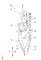
- FIG. 1 is a side elevation of a wheeled hydraulic excavator (hereafter notated as a wheel excavator 100), representing an example of the wheeled work vehicle achieved in the embodiment. It is to be noted that in the following description, the directional terms front/rear and up/down will be used as defined in FIG. 1 .
- the wheel excavator 100 includes a traveling superstructure 101 and a revolving superstructure 102 rotatably mounted upon the traveling superstructure 101.
- a traveling hydraulic motor (hereafter referred to as a "traveling motor”) is installed in the traveling superstructure 101, and wheels 105 rotate as they are driven by the traveling motor.
- An operator's cab 104 and a front work device 110 are disposed at the revolving superstructure 102.
- a counterweight 109 used to balance the body during work operation, is mounted.
- the front work device 110 includes a boom 106, an arm 107 and a bucket 108.
- the boom 106 and the arm 107 move up or down as they are driven by a boom cylinder 116 and an arm cylinder 117 respectively.
- the bucket 108, attached at the front end of the arm 107 so as to be allowed to swivel up/down relative to the arm 107, is driven by a bucket cylinder 118.
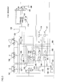
- FIG. 2 is a diagram schematically illustrating the structure of the traveling control device.
- Pressure oil (or pressurized oil) output from a main pump 130 driven by an engine 190 is delivered via a valve unit 140 to a traveling motor 115, the boom cylinder 116 and the arm cylinder 117.
- the traveling motor 115, the boom cylinder 116 and the arm cylinder 117 are driven with the pressure oil delivered thereto.
- the valve unit 140 includes a traveling directional control valve 145, a boom directional control valve 146 and an arm directional control valve 147, which are all open center type directional control valves that control the flow of pressure oil delivered to the traveling motor 115, the boom cylinder 116 and the arm cylinder 117 respectively.
- the valve unit 140 further includes a variable restrictor 161 capable of adjusting the area of an opening through which the pressure oil is distributed.
- the various directional control valves 145, 146 and 147 are all disposed on a center bypass line 191 connecting the main pump 130 with a tank (or a reservoir) 199. Namely, the traveling directional control valve 145, the boom directional control valve 146 and the arm directional control valve 147 are connected in tandem to the center bypass line 191.
- the directional control valves 145, 146 and 147 are connected in parallel through a parallel oil passage 192 branching out from the center bypass line 191 on the upstream side of the traveling directional control valve 145.
- the variable restrictor 161 is disposed in a feeder oil passage 193 branching out from the parallel oil passage 192 and connected to the traveling directional control valve 145.
- the variable restrictor 161 controls the flow rate of pressure oil delivered to the traveling motor 115.
- the variable restrictor 161 takes positions between a position (A) at which the pressure oil flow opening achieves the maximum area and a position (B) at which the pressure oil flow opening area is restricted to assume the smallest area.
- variable restrictor 161 is made to move between a position (A) and a position (B) via an electromagnetic proportional valve 162 engaged in operation by a control signal provided from a controller 120. In other words, the operation of the variable restrictor 161 is controlled by the electromagnetic proportional valve 162 and the controller 120.
- the electromagnetic proportional valve 162 is disposed in a pilot pipeline connecting a pilot pump 131 driven by the engine 190 and a pilot portion of the variable restrictor 161.
- the electromagnetic proportional valve 162 is displaced between a position (A) at which pressure oil from the pilot pump 131 is delivered to the pilot portion of the variable restrictor 161 and a position (B) at which the pressure oil from the pilot pump 131 is cut off.
- the electric current input to the solenoid in the electromagnetic proportional valve 162 from the controller 120 is represented by a greater value, the extent of displacement from the position (B) toward the position (A), too, is greater, and once the current is no longer supplied to the solenoid, a reset spring switches the electromagnetic proportional valves 162 to the position (B).
- the pressure oil from the pilot pump 131 is delivered to pilot valves disposed at a traveling operation pedal 155, a boom operation lever 156 and an arm operation lever 157.
- a given operation member among the operation members 155, 156 and 157 is operated, a secondary pilot pressure is generated via the corresponding pilot valve.
- the secondary pilot pressure thus generated via the particular pilot valve is applied to the corresponding pilot port at the traveling directional control valve 145, the boom directional control valve 146 or the arm directional control valve 147.
- the spool in the directional control valve 145, 146 or 147, corresponding to the operation member 155, 156 or 157 having been operated, is driven.
- the degree of opening at the traveling directional control valve 145 is controlled in correspondence to the operation quantity at the traveling operation pedal 155 and that as the operation quantity at the traveling operation pedal 155 increases, the flow rate of the pressure oil delivered to the traveling motor 115 increases to result in an increase in the rotation rate of the traveling motor 115.
- the wheel excavator 100 is equipped with a transmission 150 capable of reduction ratio adjustment.
- the rotation of the traveling motor 115, first slowed down at the transmission 150, is transmitted to the wheels 105 via a drive shaft (not shown) and axles (not shown), thereby enabling the wheel excavator 100 to travel.
- the transmission 150 is a system of the known art that includes a planetary reduction gear unit configured with a sun gear, a planetary gear and a ring gear (none shown), and clutches 150a and 150b disposed on the sun gear side and on the ring gear side.
- the clutches 150a and 150b each include a clutch cylinder with a built-in spring. As the clutch cylinder is pressed onto a disk with the force imparted by the spring, the corresponding clutch 150a or 150b is set in an engaged state.
- the clutches 150a and 150b are each set in a released state as a hydraulic force imparted from the pilot pump 131, which acts against the spring force, cancels out the pressing force imparted at the clutch cylinder.
- the hydraulic force that acts on the clutches 150a and 150b is controlled via the drive of an electromagnetic switching valve 151. It is to be noted that a clutch set in an engaged state by the force imparted by a spring and set in a released state by a hydraulic force is referred to as a negative-type clutch.
- the electromagnetic switching valve 151 is switched by a control signal output from the controller 120 in response to an operation at a speed change switch 158. As the electromagnetic switching valve 151 is switched to a position (A), the pressure oil from the pilot pump 131 acts on the clutch 150a. As a result, the clutch 150a is released and the clutch 150b enters the engaged state, thereby setting a predetermined reduction ratio R1 (low gear) at the transmission 150 and enabling first speed traveling at low speed and high torque.
- the electromagnetic switching valve 151 As the electromagnetic switching valve 151 is switched to a position (B), the pressure oil from the pilot pump 131 acts on the clutch 150b. As a result, the clutch 150b is released and the clutch 150a enters the engaged state, thereby setting a predetermined reduction ratio R2 (high gear) at the transmission 150 and enabling second speed traveling at high speed and low torque. It is to be noted that the reduction ratio R1 is greater than the reduction ratio R2.
- the clutches 150a and 150b are set in communication with the tank 199.
- the clutch 150a and the clutch 150b are sustained in the engaged state by the respective spring forces, and the transmission 150 is locked, thereby disallowing rotation of the drive shaft.
- the controller 120 configured so as to include an arithmetic processing device having a CPU, storage devices such as a ROM and a RAM, other peripheral circuits and the like, controls the overall system in the wheel excavator 100.
- a plurality of high pressure selection valves 196, 197 and 198 are disposed between the pressure sensor 172 and the two operation levers, i.e., the boom operation lever 156 and the arm operation lever 157, and the highest pressure among the secondary pilot pressures output from the respective pilot valves in the boom operation lever 156 and the arm operation lever 157 is detected at the pressure sensor 172.
- a high pressure selection valve 195 is disposed between the pressure sensor 171 and the traveling operation pedal 155, and the higher pressure of the secondary pilot pressures output from the pilot valves at the traveling operation pedal 155 as a forward instruction signal and a backward instruction signal is detected by the pressure sensor 171.
- the speed change switch 158 is an operation switch operated to set the transmission 150 to first gear with a greater reduction ratio or to second gear with a smaller reduction ratio. As the speed change switch 158 is operated to the first speed position, it outputs a signal for setting the transmission 150 to low gear and provides the signal to the controller 120. Upon detecting that the speed change switch 158 has been operated to the first speed position, the controller 120 outputs a control signal for switching the electromagnetic switching valve 151 to the position (A). As the speed change switch 158 is operated to the second speed position, it outputs a signal for setting the transmission 150 to high gear and provides the signal to the controller 120. Upon detecting that the speed change switch 158 has been operated to the second speed position, the controller 120 outputs a control signal for switching the electromagnetic switching valve 151 to the position (B).
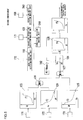
- FIG. 3 is a block diagram showing the structure of the traveling control device achieved in the first embodiment.
- FIGS. 4A to 4E indicate the characteristics based upon which the arithmetic operations are executed in the various arithmetic operation units shown in FIG. 3 .
- the controller 120 includes a first arithmetic operation unit 123 that calculates an opening area Ad at the variable restrictor 161 based upon a pressure Pd detected via the pressure sensor 171, a second arithmetic operation unit 124 that calculates an opening area Af at the variable restrictor 161 based upon a pressure Pf detected via the pressure sensor 172 and a third arithmetic operation unit 125 that calculates an opening area Ap at the variable restrictor 161 based upon a pressure Pp detected via the pressure sensor 173, all embodied as functional units.
- the first arithmetic operation unit 123 calculates the opening area Ad at the variable restrictor 161 that monotonically increases as the detection value Pd provided by the pressure sensor 171 (hereafter may be otherwise referred to as a "traveling operation pressure") increases.
- the characteristics f1 are such that while the opening area Ad is represented by the minimum value Amin as long as the detection value Pd is equal to or less than a predetermined value Pd1, the opening area Ad increases exponentially from the minimum value Amin through the maximum value Amax as the detection value Pd increases over a range between Pd1 and Pd2.
- the graph representing the characteristics f1 indicates that once the detection value Pd becomes equal to or greater than the predetermined value Pd2, the opening area Ad sustains the maximum value Amax.
- the second arithmetic operation unit 124 calculates the opening area Af at the variable restrictor 161 that monotonically decreases as the detection value Pf provided by the pressure sensor 172 (hereafter may be otherwise referred to as a "front operation pressure") increases.
- the characteristics f2 are such that while the opening area Af is represented by the maximum value Amax as long as the detection value Pf is equal to or less than a predetermined value Pf1, the opening area Af decreases exponentially from the maximum value Amax through the minimum value Amin as the detection value Pf increases over a range between Pf1 and Pf2.
- the graph representing the characteristics f2 indicates that once the detection value Pf becomes equal to or greater than the predetermined value Pf2, the opening area Af sustains the minimum value Amin.
- the third arithmetic operation unit 125 calculates the opening area Ap at the variable restrictor 161 that monotonically decreases as the detection value Pp provided by the pressure sensor 173 (hereafter may be otherwise referred to as a "pump output pressure") increases.
- the characteristics f3 are such that while the opening area Ap is represented by the maximum value Amax as long as the detection value Pp is equal to or less than a predetermined value Pp1, the opening area Ap decreases exponentially from the maximum value Amax through the minimum value Amin as the detection value Pp increases over a range between Pp1 and Pp2.
- the graph representing the characteristics f3 indicates that once the detection value Pp becomes equal to or greater than the predetermined value Pp2, the opening area Ap sustains the minimum value Amin.
- the controller 120 further includes a maximum value selection unit 126 and a minimum value selection unit 127 both embodied as functional units.
- the maximum value selection unit 126 compares the opening area Ad calculated by the first arithmetic operation unit 123 and the opening area Af calculated by the second arithmetic operation unit 124 and selects either the opening area Ad or the opening area Af that is greater than the other as a first opening area A1.
- the minimum value selection unit 127 compares the first opening area A1 selected by the maximum value selection unit 126 and the opening area Ap calculated by the third arithmetic operation unit 125 and selects either the first opening area A1 or the opening area Ap that is smaller than the other as a target opening area At.
- the controller 120 further includes functional units embodying a traveling operation decision-making unit 121 that makes a decision, based upon the pressure Pd detected by the pressure sensor 171, as to whether or not the traveling operation pedal 155 has been operated, a work operation decision-making unit 122 that makes a decision, based upon the pressure Pf detected by the pressure sensor 172, as to whether or not a work operation lever 156 or 157 has been operated, and a condition decision-making unit 180 that makes a decision, based upon the decision-making results provided by the traveling operation decision-making unit 121 and the work operation decision-making unit 122, as to whether or not a flow rate restricting condition has been established.
- the controller 120 also includes a maximum value setting unit 182 that sets the target opening area At to the maximum value Amax and a switch unit 181 that is switched based upon the decision-making results provided by the condition decision-making unit 180, both embodied as functional units.
- the traveling operation decision-making unit 121 makes a decision as to whether or not the pressure Pd detected by the pressure sensor 171 is equal to or greater than a threshold value Pt1.
- the threshold value Pt1 is stored in a storage device in advance (Pt1 ⁇ Pd1).
- the threshold value Pt1 is a threshold value used as a criterion when making a decision as to whether or not a traveling operation is underway.
- the threshold value Pt is set by taking into consideration a secondary pilot pressure generated via the pilot valve at the traveling operation pedal 155, at which the wheel excavator 100 starts traveling.
- the traveling operation decision-making unit 121 decides that no traveling operation is underway if the pressure Pd detected by the pressure sensor 171 is less than the threshold value Pt1, whereas it decides that a traveling operation is underway if the pressure Pd detected by the pressure sensor 171 is equal to or greater than the threshold value Pt1.
- the work operation decision-making unit 122 makes a decision as to whether or not the pressure Pf detected by the pressure sensor 172 is equal to or greater than a threshold value Pt2.
- the threshold value Pt2 is stored in advance in a storage device (Pt2 ⁇ Pf1).
- the threshold value Pt2 is a threshold value used as a criterion when making a decision as to whether or not the front work device 110 is currently engaged in operation.
- the threshold value Pt2 is set by taking into consideration secondary pilot pressures generated via the pilot valves at the work operation levers 156 and 157 at which the front work device 116 starts drive.
- the work operation decision-making unit 122 decides that no work operation is underway if the pressure Pf detected by the pressure sensor 172 is less than the threshold value Pt2 and decides that a work operation is underway if the pressure Pf detected by the pressure sensor 172 is equal to or greater than the threshold value Pt2.
- the condition decision-making unit 180 makes a decision, based upon signals provided by the work operation decision-making unit 122 and the traveling operation decision-making unit 121, as to whether or not a combination operation is underway, i.e., whether or not a work operation and a traveling operation are both performed. Upon deciding that a combination operation is performed, the condition decision-making unit 180 determines that a flow rate restricting condition has been established and outputs an ON signal to the switch unit 181. In response to the ON signal input thereto, the switch unit 181 is switched toward a terminal (A).
- condition decision-making unit 180 determines that the flow rate restricting condition has not been established and outputs an OFF signal to the switch unit 181. In response to the OFF signal input thereto, the switch unit 181 is switched toward a terminal (B).
- the controller 120 includes a functional unit embodying a control pressure calculation unit 128 that calculates a control pressure Pv for the electromagnetic proportional valve 162, which corresponds to either the target opening area At that is selected by the minimum value selection unit 127 and is output via the switch unit 181 when the flow rate restricting condition exists or the target opening area At that is set by the maximum value setting unit 182 and is output via the switch unit 181 when the flow rate restricting condition does not exist.
- a control pressure calculation unit 128 that calculates a control pressure Pv for the electromagnetic proportional valve 162, which corresponds to either the target opening area At that is selected by the minimum value selection unit 127 and is output via the switch unit 181 when the flow rate restricting condition exists or the target opening area At that is set by the maximum value setting unit 182 and is output via the switch unit 181 when the flow rate restricting condition does not exist.
- the control pressure calculation unit 128 calculates the control pressure Pv corresponding to the target opening area At based upon predetermined characteristics f4 indicated in FIG. 4D . As FIG. 4D indicates, the characteristics f4 are such that the electromagnetic valve control pressure Pv increases exponentially from a minimum value Pvmin through a maximum value Pvmax as the target opening area At increases over a range between Amin and Amax.
- the controller 120 further includes a functional unit embodying a current calculation unit 129 that calculates a control current I to be output to the electromagnetic proportional valve 162, which corresponds to the control pressure Pv calculated for the electromagnetic proportional valve 162 by the control pressure calculation unit 128.
- the current calculation unit 129 calculates the control current I corresponding to the control pressure Pv based upon predetermined characteristics f5 indicated in FIG. 4E .
- the controller 120 When the switch unit 181 is set at the position (A), the controller 120 outputs the control current I calculated by the current calculation unit 129 to the electromagnetic proportional valve 162 to control the variable restrictor 161 so that the opening area at the variable restrictor 161 matches the opening area having been selected by the minimum value selection unit 127.
- the controller 120 controls the variable restrictor 161 so that the opening area at the variable restrictor 161 becomes smaller than that in the traveling operation-only state, thereby minimizing or preventing the bucking phenomenon at the wheel excavator 100.
- the work operation decision-making unit 122 in the controller 120 decides that no work operation is underway. While the traveling operation pedal 155 is not operated, the traveling operation pressure Pd remains equal to or less than Pd1. Accordingly, the traveling operation decision-making unit 121 in the controller 120 decides that no traveling operation is underway. Under these circumstances, based upon the decision-making results provided by the work operation decision-making unit 122 and the traveling operation decision-making unit 121, the condition decision-making unit 180 decides that the flow rate restricting condition has not been established.
- the controller 120 switches the switch unit 181 to the position (B) so as to set the target opening area At for the variable restrictor 161 to the maximum value Amax by cutting off the minimum value selection unit 127 from the control pressure calculation unit 128.
- the electromagnetic proportional valve 162 is switched to the position (A) and the variable restrictor 161 is switched to the position (A).
- the traveling operation pedal 155 in the wheel excavator in this non-operating state is operated to a very small extent, the spool in the traveling directional control valve 145 becomes displaced in correspondence to the operation quantity at the traveling operation pedal 155, and, as a result, pressure oil output from the main pump 130 is delivered to the traveling motor 115 via the traveling directional control valve 145.
- the pressure oil delivered to the traveling motor 115 rotationally drives the traveling motor 115 and the wheel excavator 100 thus starts to travel.
- the work operation decision-making unit 122 decides that no work operation is underway. Based upon these decision-making results, the condition decision-making unit 180 decides that the flow rate restricting condition has not been established and accordingly, the variable restrictor 161 is held at the position (A).
- the operation of the boom operation lever 156 is detected by the pressure sensor 172 and the detection results are input to the controller 120.
- the work operation decision-making unit 122 accordingly decides that a front work operation is underway and the traveling operation decision-making unit 121 1 decides that a traveling operation is underway.
- the condition decision-making unit 180 decides that the flow rate restricting condition has been established.
- the switch unit 181 is switched to the position (A) at which the minimum value selection unit 127 and the control pressure calculation unit 128 are connected with each other, and thus, the opening area selected by the minimum value selection unit 127 is input to the control pressure calculation unit 128 as the target opening area At.
- the flow rate of the pressure oil delivered to the traveling motor 115 is restricted via the variable restrictor 161 controlled so as to achieve either the opening area calculated in correspondence to the operation quantity at the work operation lever 156 or 157 or the opening area calculated in correspondence to the pump output pressure Pp that is smaller than the other.
- the variables restrictor 161 is switched to the position (B) and, as a result, the flow rate of the pressure oil delivered to the traveling motor 115 is reduced compared to that in the traveling operation-only state.
- an increase in the flow rate of pressure oil delivered to the traveling motor 115, attributable to an operation at the front work device, can be minimized while the wheel excavator 100 is traveling at low speed.
- the severity of bucking occurring at the wheel excavator 100, occurring as a front work operation is performed while the wheel excavator 100 is traveling, is reduced or prevented altogether.
- the flow rate of pressure oil delivered to the traveling motor 115 is never restricted via the variable restrictor 161 in the traveling operation-only state. For instance, even as the pump output pressure Pp rises while the wheel excavator is traveling uphill, the opening area at the variable restrictor 161 does not decrease in conformance to the characteristics f3 and thus, the traveling drive force does not become lowered.
- FIG. 5 shows the structure of the traveling control device achieved in the second embodiment of the present invention in a block diagram similar to that presented in FIG. 3 .
- condition decision-making unit 180 makes a decision as to whether or not the flow rate restricting condition has been established based upon the decision-making results provided by the traveling operation decision-making unit 121 and the work operation decision-making unit 122.
- the second embodiment is distinguishable in that a condition decision-making unit 280 makes a decision as to whether or not the flow rate restricting condition has been established based upon decision-making results provided by a reduction ratio decision-making unit 283 in addition to the decision-making results provided by the traveling operation decision-making unit 121 and the work operation decision-making unit 122.
- the controller 120 includes a functional unit embodying the reduction ratio decision-making unit 283 that makes a decision, in response to a control signal output from the speed change switch 158, as to whether or not the reduction ratio is equal to or greater than a predetermined value.
- the reduction ratio decision-making unit 283 decides that the reduction ratio is equal to or greater than the predetermined value, whereas if the speed change switch 158 is set at second speed position, the reduction ratio decision-making unit 283 decides that the reduction ratio is less than the predetermined value.
- the condition decision-making unit 280 makes a decision, based upon signals provided by the work operation decision-making unit 122 and the traveling operation decision-making unit 121, as to whether or not the combination operation is underway, i.e., both a work operation and a traveling operation are currently in progress, and also makes a decision, based upon a signal provided by the reduction ratio decision-making unit 283, as to whether or not the reduction ratio is equal to or greater than the predetermined value.
- the condition decision-making unit 280 determines that the flow rate restricting condition has been established and outputs an ON signal to the switch unit 181.
- the switch unit 181 In response to the ON signal input thereto, the switch unit 181 is switched toward the terminal (A). Upon determining, based upon the signals provided by the work operation decision-making unit 122, the traveling operation decision-making unit 121 and the reduction ratio decision-making unit 283, that a work operation or a traveling operation is not currently underway or that the reduction ratio is less than the predetermined value, the condition decision-making unit 280 decides that the flow rate restricting condition has not been established, and outputs an OFF signal to the switch unit 181. In response to the OFF signal input thereto, the switch unit 181 is switched toward the terminal (B).
- the controller 120 in the second embodiment determines that the flow rate restricting condition has been established if a traveling operation pressure Pd equal to or greater than the predetermined value Pt1 is detected, a front operation pressure Pf equal to or greater than the predetermined value Pt2 is detected and a reduction ratio equal to or greater than the predetermined value is detected.
- the controller 120 switches the switch unit 181 to the position (A) so as to enable control under which the flow rate is restricted via the variable restrictor 161 in correspondence to the traveling operation pressure Pd, the front operation pressure Pf and the pump output pressure Pp. If, on the other hand, it is determined that the flow rate restricting condition has not been established, the controller 120 switches the switch unit 181 to the position (B) so as to disable the control for restricting the flow rate via the variable restrictor 161.
- the second embodiment described above further achieves the following advantage.
- the bucking phenomenon occurs as the output pressure at the main pump 130 is applied to the low pressure-side traveling motor 115, rather than to the actuators for the high pressure-side front operation device in response to a work operation performed to, for instance, raise the boom while the work vehicle is traveling at crawling speed (i.e., very low speed) or at low speed, at which the traveling drive pressure is relatively low.
- flow rate restriction control under which the flow rate of pressure oil to be delivered to the traveling motor 115 is restricted via the variable restrictor 161 is executed when the reduction ratio is high, i.e., when the traveling motor drive pressure is low, so as to reduce the extent of the bucking phenomenon or prevent it altogether.
- the reduction ratio is low, i.e., when the traveling motor drive pressure is high, the bucking phenomenon does not occur as readily as under the high reduction ratio condition.
- the flow rate restriction control under which the flow rate of pressure oil to be delivered to the traveling motor 115 is restricted via the variable restrictor 161 is not executed. Through these measures, it is ensured that the drive force of the traveling motor 115 is not lowered as the work vehicle shifts from the traveling operation-only state into the combination operation state under the low reduction ratio condition.
- FIG. 6 illustrates the structure of the traveling control device achieved in the third embodiment of the present invention in a schematic diagram similar to that presented in FIG. 2 .
- the traveling control device achieved in the third embodiment includes a pressure sensor 374 that detects the pressure in either a main pipeline LA or a main pipeline LB at the traveling motor 115, selected via a high-pressure selection valve 394, i.e., the pressure (traveling drive pressure Pm) of the pressure oil delivered to the traveling motor 115.
- the pressure traveling drive pressure Pm
- the opening area at the variable restrictor 161 is set in the third embodiment by factoring in characteristics f6 whereby the opening area is reduced as the traveling drive pressure Pm becomes lower and the opening area is increased as the traveling drive pressure Pm becomes higher.
- FIG. 7 shows the structure of the traveling control device achieved in the third embodiment of the present invention in a block diagram similar to that presented in FIG. 3 .
- FIG. 8 presents a diagram indicating characteristics representing the relationship between the traveling drive pressure Pm and an opening area Am, based upon which the arithmetic operation is executed in a fourth arithmetic operation unit 384 shown in FIG. 7 .
- the controller 120 in the third embodiment includes functional units embodying the fourth arithmetic operation unit 384 that calculates the opening area Am for the variable restrictor 161 based upon the pressure Pm detected by the pressure sensor 374, a maximum value selection unit 326 and a minimum value selection unit 327.
- the fourth arithmetic operation unit 384 calculates, based upon the predetermined characteristics f6 shown in FIG. 8 , the opening area Am at the variable restrictor 161 that monotonically increases as the detection value (traveling drive pressure) Pm provided by the pressure sensor 374 increases.
- the characteristics f6 are such that while the detection value Pm remains equal to or less than a predetermined value Pm1, the opening area Am is sustained at a minimum value Amin and that the opening area Am increases exponentially from the minimum value Amin through a maximum value Amax as the detection value Pm increases over a detection value range between Pm1 and Pm2.
- the opening area Am taking on the characteristics f6 is sustained at the maximum value Amax once the detection value Pm becomes equal to or greater than the predetermined value Pm2.
- the maximum value selection unit 326 compares the opening area Ap calculated by the third arithmetic operation unit 125 with the opening area Am calculated by the fourth arithmetic operation unit 384 and selects either the opening area Ap or the opening area Am that is greater than the other as a second opening area A2.
- the minimum value selection unit 327 compares the first opening area A1 selected by the maximum value selection unit 126 with the second opening area A2 selected by the maximum value selection unit 326 and selects either the first opening area A1 or the second opening area A2 that is smaller than the other as the target opening area At.
- variable restrictor 161 is switched to the position (B) when the traveling operation pressure Pd and the front operation pressure Pf are both low (e.g., Pt1 ⁇ Pd ⁇ Pd1 and Pt2 ⁇ Pf ⁇ Pf1) and the pump output pressure Pp is high (e.g., Pp ⁇ Pp2).
- variable restrictor 161 is switched to the position (A) if the traveling drive pressure Pm is high (e.g., Pm ⁇ Pm2) even when the traveling operation pressure Pd and the front operation pressure Pf are both low (e.g., Pt1 ⁇ Pd ⁇ Pd1 and Pt2 ⁇ Pf ⁇ Pf1) and the pump output pressure Pp is high (e.g., Pp ⁇ Pp2).
- the third embodiment is characterized as follows;
- the third embodiment described above further achieves the following advantage.
- the bucking phenomenon occurs as the output pressure at the main pump 130 is applied to the low pressure-side traveling motor 115, rather than to the actuators for the high pressure-side front operation device in response to a work operation performed to, for instance, raise the boom while the work vehicle is traveling at crawling speed or at low speed, at which the traveling drive pressure is relatively low.
- flow rate restriction control under which the flow rate of pressure oil to be delivered to the traveling motor 115 is restricted by the variable restrictor 161 is executed in order to reduce the extent of the bucking phenomenon or prevent it altogether, if, for instance, the boom operation lever 156 is operated to a very small extent (e.g., Pt2 ⁇ Pf ⁇ Pf1) while the traveling drive pressure is low in order to engage the work vehicle, traveling at low speed with a low traveling operation pressure Pd (e.g., Pt1 ⁇ Pd ⁇ Pd1), in heavy-load work.
- a very small extent e.g., Pt2 ⁇ Pf ⁇ Pf1
- Pd e.g., Pt1 ⁇ Pd ⁇ Pd1
- the boom is operated at a high traveling drive pressure condition, the bucking phenomenon does not occur as readily as at a low traveling drive pressure, and accordingly, the flow rate restriction control for restricting the flow rate of pressure oil to be delivered to the traveling motor 115 via the variable restrictor 161 is not executed in this situation.
- the drive force at the traveling motor 115 can be sustained at a sufficient level while the traveling drive pressure remains high.
Landscapes
- Engineering & Computer Science (AREA)
- General Engineering & Computer Science (AREA)
- Mining & Mineral Resources (AREA)
- Civil Engineering (AREA)
- Structural Engineering (AREA)
- Physics & Mathematics (AREA)
- Fluid Mechanics (AREA)
- Mechanical Engineering (AREA)
- Operation Control Of Excavators (AREA)
- Fluid-Pressure Circuits (AREA)
Abstract

Description
- The disclosure of the following priority application is herein incorporated by reference: Japanese patent application No.
2013-059726 filed March 22, 2013 - The present invention relates to a traveling control device for a wheeled work vehicle such as a wheeled hydraulic excavator.
- A wheeled hydraulic excavator is an example of a wheeled work vehicle. A wheeled hydraulic excavator includes a wheel type traveling superstructure equipped with four wheels, a revolving superstructure rotatably disposed upon the traveling superstructure and a front work device disposed at a substantially central position on the front side of the revolving superstructure, which includes a boom, an arm and a bucket.
- A traveling motor used to drive the traveling superstructure and hydraulic actuators used to drive the front work device are mounted at the wheeled hydraulic excavator. The flow of pressure oil delivered from a hydraulic pump to the traveling motor is controlled via a traveling directional control valve, whereas the flow of pressure oil delivered from the hydraulic pump to the hydraulic actuators for the front work device is controlled by a work directional control valve.
- Japanese Laid Open Patent Publication No.
2002-130003 - The drive pressure for the traveling motor (hereafter referred to as "traveling drive pressure") in a wheeled hydraulic excavator is lower than the drive pressures for the hydraulic actuators functioning as work operation drive sources. In particular, it is lower than the drive pressure for the boom cylinder. Thus, if the boom is raised while the wheeled hydraulic excavator, with the traveling directional control valve and the work directional control valve thereof disposed on the center bypass line and connected in parallel to the hydraulic pump, is crawling (i.e., traveling at very low speed) or traveling at low speed, with a relatively low traveling drive pressure, the output pressure at the hydraulic pump will be applied to the lower pressure-side traveling motor rather than to the high pressure-side boom cylinder. As a result, the quantity of pressure oil flowing into the traveling motor will increase sharply, i.e., the traveling speed will rise abruptly, causing the wheeled hydraulic excavator to jerk or surge (hereafter referred to as "bucking"). Such bucking is bound to be an unpleasant experience for the operator riding in the work vehicle crawling or traveling at low speed.
- A traveling control device for a wheeled work vehicle according to a first aspect of the present invention comprises: a hydraulic pump driven by an engine; a traveling motor driven with pressure oil output from the hydraulic pump; a work device actuator that is driven with pressure oil from the hydraulic pump and drives a front work device; a traveling directional control valve via which a flow of pressure oil from the hydraulic pump to the traveling motor is controlled, and a work device directional control valve via which a flow of pressure oil from the hydraulic pump to the work device actuator is controlled, with the traveling directional control valve and the work device directional control valve disposed on a center bypass line at the hydraulic pump; a flow control valve disposed on an upstream side of the traveling directional control valve, that controls a flow rate of the pressure oil from the hydraulic pump to the traveling motor; a traveling operation member operated to engage the traveling motor in operation; a work operation member operated to engage the work device actuator in operation; a traveling operation quantity detection means for detecting a traveling operation quantity representing an extent of operation of the traveling operation member; a work operation quantity detection means for detecting a work operation quantity representing an extent of operation of the work operation member; an output pressure detection means for detecting an output pressure of the hydraulic pump; and/or a valve control means for controlling the flow control valve in correspondence to the traveling operation quantity detected by the traveling operation quantity detection means, the work operation quantity detected by the work operation quantity detection means and the output pressure of the hydraulic pump detected by the output pressure detection means, wherein: the valve control means controls the flow rate of pressure oil delivered to the traveling motor so as to deter bucking of the wheeled work vehicle if the wheeled work vehicle, currently in a traveling operation-only state in which the traveling operation member is operated but the work operation member is not operated, shifts into a combination operation state in which the traveling operation member is operated and the work operation member is also operated.
- According to a second aspect of the present invention, the traveling control device for a wheeled work vehicle according to the first aspect may further comprise: a motor pressure detection means for detecting a pressure of pressure oil delivered to the traveling motor, wherein: the valve control means controls the flow control valve by factoring in the pressure detected by the motor pressure detection means.
- According to a third aspect of the present invention, in the traveling control device for a wheeled work vehicle according to the first or second aspect, it is preferable that the valve control means deters the bucking of the wheeled work vehicle when shifting from the traveling operation-only state into the combination operation state by controlling the flow control valve so as to achieve a smaller opening area at the flow control valve than the opening area achieved at the flow control valve in the traveling operation-only state.
- According to a fourth aspect of the present invention, the traveling control device for a wheeled work vehicle according to any one of the first to third aspects may further comprise: a condition decision-making means for determining that a flow rate restricting condition has been established when a traveling operation quantity equal to or greater than a predetermined value is detected by the traveling operation quantity detection means and a work operation quantity equal to or greater than a predetermined value is detected by the work operation quantity detection means; and an enabling/disabling means for enabling the valve control means to control the flow control valve when the condition decision-making means determines that the flow rate restricting condition has been established and disabling control of the flow control valve by the valve control means when the condition decision-making means determines that the flow rate restricting condition has not been established.
- According to a fifth aspect of the present invention, the traveling control device for a wheeled work vehicle according to any one of the first to third aspects may further comprise: a reduction mechanism, capable of altering a reduction ratio, that slows down rotation of the traveling motor and transmits the slowed rotation to wheels; a reduction ratio detection means for detecting the reduction ratio at the reduction mechanism; a condition decision-making means for determining that a flow rate restricting condition has been established when a traveling operation quantity equal to or greater than a predetermined value is detected by the traveling operation quantity detection means, a work operation quantity equal to or greater than a predetermined value is detected by the work operation quantity detection means and a reduction ratio equal to or greater than a predetermined value is detected by the reduction ratio detection means; and an enabling/disabling means for enabling the valve control means to control the flow control valve when the condition decision-making means determines that the flow rate restricting condition has been established and disabling control of the flow control valve by the valve control means when the condition decision-making means determines that the flow rate restricting means has not been established.
-
-
FIG. 1 is a side elevation of a wheel excavator adopting the traveling control device according to the present invention. -
FIG. 2 schematically illustrates the structure of the traveling control device achieved in a first embodiment. -
FIG. 3 is a block diagram showing the structure of the traveling control device achieved in the first embodiment. -
FIGS. 4A to 4E present diagrams indicating the characteristics based upon which the arithmetic operations are executed in the various arithmetic operation units shown inFIG. 3 . -
FIG. 5 is a block diagram showing the structure of the traveling control device achieved in a second embodiment. -
FIG. 6 schematically illustrates the structure of the traveling control device achieved in a third embodiment. -
FIG. 7 is a block diagram showing the structure of the traveling control device achieved in the third embodiment. -
FIG. 8 presents a graph indicating the characteristics based upon which an arithmetic operation is executed in the fourth arithmetic operation unit shown inFIG. 7 . - The following is a description of an embodiment of a wheeled work vehicle that adopts the traveling control device according to the present invention, given in reference to drawings.
-
FIG. 1 is a side elevation of a wheeled hydraulic excavator (hereafter notated as a wheel excavator 100), representing an example of the wheeled work vehicle achieved in the embodiment. It is to be noted that in the following description, the directional terms front/rear and up/down will be used as defined inFIG. 1 . - The
wheel excavator 100 includes atraveling superstructure 101 and a revolvingsuperstructure 102 rotatably mounted upon thetraveling superstructure 101. A traveling hydraulic motor (hereafter referred to as a "traveling motor") is installed in thetraveling superstructure 101, andwheels 105 rotate as they are driven by the traveling motor. An operator'scab 104 and afront work device 110 are disposed at the revolvingsuperstructure 102. At the rear of the revolvingsuperstructure 102, acounterweight 109, used to balance the body during work operation, is mounted. - The
front work device 110 includes aboom 106, anarm 107 and abucket 108. Theboom 106 and thearm 107 move up or down as they are driven by aboom cylinder 116 and anarm cylinder 117 respectively. Thebucket 108, attached at the front end of thearm 107 so as to be allowed to swivel up/down relative to thearm 107, is driven by abucket cylinder 118. -
FIG. 2 is a diagram schematically illustrating the structure of the traveling control device. Pressure oil (or pressurized oil) output from amain pump 130 driven by anengine 190 is delivered via avalve unit 140 to a travelingmotor 115, theboom cylinder 116 and thearm cylinder 117. The travelingmotor 115, theboom cylinder 116 and thearm cylinder 117 are driven with the pressure oil delivered thereto. - The
valve unit 140 includes a travelingdirectional control valve 145, a boomdirectional control valve 146 and an armdirectional control valve 147, which are all open center type directional control valves that control the flow of pressure oil delivered to thetraveling motor 115, theboom cylinder 116 and thearm cylinder 117 respectively. Thevalve unit 140 further includes avariable restrictor 161 capable of adjusting the area of an opening through which the pressure oil is distributed. The variousdirectional control valves center bypass line 191 connecting themain pump 130 with a tank (or a reservoir) 199. Namely, the travelingdirectional control valve 145, the boomdirectional control valve 146 and the armdirectional control valve 147 are connected in tandem to thecenter bypass line 191. - The
directional control valves parallel oil passage 192 branching out from thecenter bypass line 191 on the upstream side of the travelingdirectional control valve 145. Thevariable restrictor 161 is disposed in afeeder oil passage 193 branching out from theparallel oil passage 192 and connected to the travelingdirectional control valve 145. Thevariable restrictor 161 controls the flow rate of pressure oil delivered to the travelingmotor 115. Thevariable restrictor 161 takes positions between a position (A) at which the pressure oil flow opening achieves the maximum area and a position (B) at which the pressure oil flow opening area is restricted to assume the smallest area. - The
variable restrictor 161 is made to move between a position (A) and a position (B) via an electromagneticproportional valve 162 engaged in operation by a control signal provided from acontroller 120. In other words, the operation of thevariable restrictor 161 is controlled by the electromagneticproportional valve 162 and thecontroller 120. - The electromagnetic
proportional valve 162 is disposed in a pilot pipeline connecting apilot pump 131 driven by theengine 190 and a pilot portion of thevariable restrictor 161. The electromagneticproportional valve 162 is displaced between a position (A) at which pressure oil from thepilot pump 131 is delivered to the pilot portion of thevariable restrictor 161 and a position (B) at which the pressure oil from thepilot pump 131 is cut off. When the electric current input to the solenoid in the electromagneticproportional valve 162 from thecontroller 120 is represented by a greater value, the extent of displacement from the position (B) toward the position (A), too, is greater, and once the current is no longer supplied to the solenoid, a reset spring switches the electromagneticproportional valves 162 to the position (B). - The pressure oil from the
pilot pump 131 is delivered to pilot valves disposed at atraveling operation pedal 155, aboom operation lever 156 and anarm operation lever 157. As a given operation member among theoperation members directional control valve 145, the boomdirectional control valve 146 or the armdirectional control valve 147. Thus, in correspondence to the operation quantity representing the extent to which a given operation member among theoperation members directional control valve operation member - It is to be noted that in this embodiment, the degree of opening at the traveling
directional control valve 145 is controlled in correspondence to the operation quantity at thetraveling operation pedal 155 and that as the operation quantity at thetraveling operation pedal 155 increases, the flow rate of the pressure oil delivered to the travelingmotor 115 increases to result in an increase in the rotation rate of the travelingmotor 115. - The
wheel excavator 100 is equipped with atransmission 150 capable of reduction ratio adjustment. The rotation of the travelingmotor 115, first slowed down at thetransmission 150, is transmitted to thewheels 105 via a drive shaft (not shown) and axles (not shown), thereby enabling thewheel excavator 100 to travel. - The
transmission 150 is a system of the known art that includes a planetary reduction gear unit configured with a sun gear, a planetary gear and a ring gear (none shown), andclutches clutches corresponding clutch clutches pilot pump 131, which acts against the spring force, cancels out the pressing force imparted at the clutch cylinder. The hydraulic force that acts on theclutches electromagnetic switching valve 151. It is to be noted that a clutch set in an engaged state by the force imparted by a spring and set in a released state by a hydraulic force is referred to as a negative-type clutch. - The
electromagnetic switching valve 151 is switched by a control signal output from thecontroller 120 in response to an operation at aspeed change switch 158. As theelectromagnetic switching valve 151 is switched to a position (A), the pressure oil from thepilot pump 131 acts on the clutch 150a. As a result, the clutch 150a is released and the clutch 150b enters the engaged state, thereby setting a predetermined reduction ratio R1 (low gear) at thetransmission 150 and enabling first speed traveling at low speed and high torque. - As the
electromagnetic switching valve 151 is switched to a position (B), the pressure oil from thepilot pump 131 acts on the clutch 150b. As a result, the clutch 150b is released and the clutch 150a enters the engaged state, thereby setting a predetermined reduction ratio R2 (high gear) at thetransmission 150 and enabling second speed traveling at high speed and low torque. It is to be noted that the reduction ratio R1 is greater than the reduction ratio R2. - As the
electromagnetic switching valve 151 is switched to a position (C), theclutches tank 199. In this situation, the clutch 150a and the clutch 150b are sustained in the engaged state by the respective spring forces, and thetransmission 150 is locked, thereby disallowing rotation of the drive shaft. - The
controller 120, configured so as to include an arithmetic processing device having a CPU, storage devices such as a ROM and a RAM, other peripheral circuits and the like, controls the overall system in thewheel excavator 100. - A
pressure sensor 172 used to detect either the operation quantity at theboom operation lever 156 or the operation quantity at thearm operation lever 157 that is greater than the other, apressure sensor 171 used to detect the operation quantity at the travelingoperation pedal 155, thespeed change switch 158, and apressure sensor 173 used to detect the output pressure at themain pump 130 are connected to thecontroller 120. - A plurality of high
pressure selection valves pressure sensor 172 and the two operation levers, i.e., theboom operation lever 156 and thearm operation lever 157, and the highest pressure among the secondary pilot pressures output from the respective pilot valves in theboom operation lever 156 and thearm operation lever 157 is detected at thepressure sensor 172. - A high
pressure selection valve 195 is disposed between thepressure sensor 171 and the travelingoperation pedal 155, and the higher pressure of the secondary pilot pressures output from the pilot valves at the travelingoperation pedal 155 as a forward instruction signal and a backward instruction signal is detected by thepressure sensor 171. - The
speed change switch 158 is an operation switch operated to set thetransmission 150 to first gear with a greater reduction ratio or to second gear with a smaller reduction ratio. As thespeed change switch 158 is operated to the first speed position, it outputs a signal for setting thetransmission 150 to low gear and provides the signal to thecontroller 120. Upon detecting that thespeed change switch 158 has been operated to the first speed position, thecontroller 120 outputs a control signal for switching theelectromagnetic switching valve 151 to the position (A). As thespeed change switch 158 is operated to the second speed position, it outputs a signal for setting thetransmission 150 to high gear and provides the signal to thecontroller 120. Upon detecting that thespeed change switch 158 has been operated to the second speed position, thecontroller 120 outputs a control signal for switching theelectromagnetic switching valve 151 to the position (B). -
FIG. 3 is a block diagram showing the structure of the traveling control device achieved in the first embodiment.FIGS. 4A to 4E indicate the characteristics based upon which the arithmetic operations are executed in the various arithmetic operation units shown inFIG. 3 . Thecontroller 120 includes a firstarithmetic operation unit 123 that calculates an opening area Ad at thevariable restrictor 161 based upon a pressure Pd detected via thepressure sensor 171, a secondarithmetic operation unit 124 that calculates an opening area Af at thevariable restrictor 161 based upon a pressure Pf detected via thepressure sensor 172 and a thirdarithmetic operation unit 125 that calculates an opening area Ap at thevariable restrictor 161 based upon a pressure Pp detected via thepressure sensor 173, all embodied as functional units. - Based upon predetermined characteristics f1 indicated in
FIG. 4A , the firstarithmetic operation unit 123 calculates the opening area Ad at thevariable restrictor 161 that monotonically increases as the detection value Pd provided by the pressure sensor 171 (hereafter may be otherwise referred to as a "traveling operation pressure") increases. AsFIG. 4A indicates, the characteristics f1 are such that while the opening area Ad is represented by the minimum value Amin as long as the detection value Pd is equal to or less than a predetermined value Pd1, the opening area Ad increases exponentially from the minimum value Amin through the maximum value Amax as the detection value Pd increases over a range between Pd1 and Pd2. The graph representing the characteristics f1 indicates that once the detection value Pd becomes equal to or greater than the predetermined value Pd2, the opening area Ad sustains the maximum value Amax. - Based upon predetermined characteristics f2 indicated in
FIG. 4B , the secondarithmetic operation unit 124 calculates the opening area Af at thevariable restrictor 161 that monotonically decreases as the detection value Pf provided by the pressure sensor 172 (hereafter may be otherwise referred to as a "front operation pressure") increases. AsFIG. 4B indicates, the characteristics f2 are such that while the opening area Af is represented by the maximum value Amax as long as the detection value Pf is equal to or less than a predetermined value Pf1, the opening area Af decreases exponentially from the maximum value Amax through the minimum value Amin as the detection value Pf increases over a range between Pf1 and Pf2. The graph representing the characteristics f2 indicates that once the detection value Pf becomes equal to or greater than the predetermined value Pf2, the opening area Af sustains the minimum value Amin. - Based upon predetermined characteristics f3 indicated in
FIG. 4C , the thirdarithmetic operation unit 125 calculates the opening area Ap at thevariable restrictor 161 that monotonically decreases as the detection value Pp provided by the pressure sensor 173 (hereafter may be otherwise referred to as a "pump output pressure") increases. AsFIG. 4C indicates, the characteristics f3 are such that while the opening area Ap is represented by the maximum value Amax as long as the detection value Pp is equal to or less than a predetermined value Pp1, the opening area Ap decreases exponentially from the maximum value Amax through the minimum value Amin as the detection value Pp increases over a range between Pp1 and Pp2. The graph representing the characteristics f3 indicates that once the detection value Pp becomes equal to or greater than the predetermined value Pp2, the opening area Ap sustains the minimum value Amin. - As shown in
FIG. 3 , thecontroller 120 further includes a maximumvalue selection unit 126 and a minimumvalue selection unit 127 both embodied as functional units. The maximumvalue selection unit 126 compares the opening area Ad calculated by the firstarithmetic operation unit 123 and the opening area Af calculated by the secondarithmetic operation unit 124 and selects either the opening area Ad or the opening area Af that is greater than the other as a first opening area A1. - The minimum
value selection unit 127 compares the first opening area A1 selected by the maximumvalue selection unit 126 and the opening area Ap calculated by the thirdarithmetic operation unit 125 and selects either the first opening area A1 or the opening area Ap that is smaller than the other as a target opening area At. - The
controller 120 further includes functional units embodying a traveling operation decision-making unit 121 that makes a decision, based upon the pressure Pd detected by thepressure sensor 171, as to whether or not the travelingoperation pedal 155 has been operated, a work operation decision-making unit 122 that makes a decision, based upon the pressure Pf detected by thepressure sensor 172, as to whether or not awork operation lever making unit 180 that makes a decision, based upon the decision-making results provided by the traveling operation decision-making unit 121 and the work operation decision-making unit 122, as to whether or not a flow rate restricting condition has been established. Thecontroller 120 also includes a maximumvalue setting unit 182 that sets the target opening area At to the maximum value Amax and aswitch unit 181 that is switched based upon the decision-making results provided by the condition decision-making unit 180, both embodied as functional units. - The traveling operation decision-
making unit 121 makes a decision as to whether or not the pressure Pd detected by thepressure sensor 171 is equal to or greater than a threshold value Pt1. The threshold value Pt1 is stored in a storage device in advance (Pt1 ≤ Pd1). The threshold value Pt1 is a threshold value used as a criterion when making a decision as to whether or not a traveling operation is underway. The threshold value Pt is set by taking into consideration a secondary pilot pressure generated via the pilot valve at the travelingoperation pedal 155, at which thewheel excavator 100 starts traveling. The traveling operation decision-making unit 121 decides that no traveling operation is underway if the pressure Pd detected by thepressure sensor 171 is less than the threshold value Pt1, whereas it decides that a traveling operation is underway if the pressure Pd detected by thepressure sensor 171 is equal to or greater than the threshold value Pt1. - The work operation decision-
making unit 122 makes a decision as to whether or not the pressure Pf detected by thepressure sensor 172 is equal to or greater than a threshold value Pt2. The threshold value Pt2 is stored in advance in a storage device (Pt2 ≤ Pf1). The threshold value Pt2 is a threshold value used as a criterion when making a decision as to whether or not thefront work device 110 is currently engaged in operation. The threshold value Pt2 is set by taking into consideration secondary pilot pressures generated via the pilot valves at the work operation levers 156 and 157 at which thefront work device 116 starts drive. The work operation decision-making unit 122 decides that no work operation is underway if the pressure Pf detected by thepressure sensor 172 is less than the threshold value Pt2 and decides that a work operation is underway if the pressure Pf detected by thepressure sensor 172 is equal to or greater than the threshold value Pt2. - The condition decision-
making unit 180 makes a decision, based upon signals provided by the work operation decision-making unit 122 and the traveling operation decision-making unit 121, as to whether or not a combination operation is underway, i.e., whether or not a work operation and a traveling operation are both performed. Upon deciding that a combination operation is performed, the condition decision-making unit 180 determines that a flow rate restricting condition has been established and outputs an ON signal to theswitch unit 181. In response to the ON signal input thereto, theswitch unit 181 is switched toward a terminal (A). Upon deciding, based upon the signals provided by the work operation decision-making unit 122 and the traveling operation decision-making unit 121, that a work operation is not underway or a traveling operation is not underway, the condition decision-making unit 180 determines that the flow rate restricting condition has not been established and outputs an OFF signal to theswitch unit 181. In response to the OFF signal input thereto, theswitch unit 181 is switched toward a terminal (B). - In addition, the
controller 120 includes a functional unit embodying a controlpressure calculation unit 128 that calculates a control pressure Pv for the electromagneticproportional valve 162, which corresponds to either the target opening area At that is selected by the minimumvalue selection unit 127 and is output via theswitch unit 181 when the flow rate restricting condition exists or the target opening area At that is set by the maximumvalue setting unit 182 and is output via theswitch unit 181 when the flow rate restricting condition does not exist. - The control
pressure calculation unit 128 calculates the control pressure Pv corresponding to the target opening area At based upon predetermined characteristics f4 indicated inFIG. 4D . AsFIG. 4D indicates, the characteristics f4 are such that the electromagnetic valve control pressure Pv increases exponentially from a minimum value Pvmin through a maximum value Pvmax as the target opening area At increases over a range between Amin and Amax. - The
controller 120 further includes a functional unit embodying acurrent calculation unit 129 that calculates a control current I to be output to the electromagneticproportional valve 162, which corresponds to the control pressure Pv calculated for the electromagneticproportional valve 162 by the controlpressure calculation unit 128. - The
current calculation unit 129 calculates the control current I corresponding to the control pressure Pv based upon predetermined characteristics f5 indicated inFIG. 4E . AsFIG. 4E indicates, the characteristics f5 are such that the control current I increases exponentially from a minimum value Imin = 0 through a maximum value Imax as the control pressure Pv increases over a range between Pvmin and Pvmax. - When the
switch unit 181 is set at the position (A), thecontroller 120 outputs the control current I calculated by thecurrent calculation unit 129 to the electromagneticproportional valve 162 to control thevariable restrictor 161 so that the opening area at thevariable restrictor 161 matches the opening area having been selected by the minimumvalue selection unit 127. - As the wheel excavator shifts from a traveling operation-only state, in which the traveling
operation pedal 155 is operated but neither the boomoperational lever 156 nor thearm operation lever 157 is operated, to a combination operation state in which the travelingoperation pedal 155 is operated and theboom operation lever 156 or thearm operation lever 157 is also operated, thecontroller 120 controls thevariable restrictor 161 so that the opening area at thevariable restrictor 161 becomes smaller than that in the traveling operation-only state, thereby minimizing or preventing the bucking phenomenon at thewheel excavator 100. - The primary operations of the traveling control device for the
wheel excavator 100 achieved in the first embodiment will be described next. - While neither the
boom operation lever 156 nor thearm operation lever 157 is operated, the front operation pressure Pf remains equal to or less than Pf1. Accordingly, the work operation decision-making unit 122 in thecontroller 120 decides that no work operation is underway. While the travelingoperation pedal 155 is not operated, the traveling operation pressure Pd remains equal to or less than Pd1. Accordingly, the traveling operation decision-making unit 121 in thecontroller 120 decides that no traveling operation is underway. Under these circumstances, based upon the decision-making results provided by the work operation decision-making unit 122 and the traveling operation decision-making unit 121, the condition decision-making unit 180 decides that the flow rate restricting condition has not been established. - When the flow rate restricting condition is not present, the
controller 120 switches theswitch unit 181 to the position (B) so as to set the target opening area At for thevariable restrictor 161 to the maximum value Amax by cutting off the minimumvalue selection unit 127 from the controlpressure calculation unit 128. Thecontroller 120 then executes processing for outputting the control current I = Imax to the solenoid in the electromagneticproportional valve 162. As a result, the electromagneticproportional valve 162 is switched to the position (A) and thevariable restrictor 161 is switched to the position (A). - As the traveling
operation pedal 155 in the wheel excavator in this non-operating state is operated to a very small extent, the spool in the travelingdirectional control valve 145 becomes displaced in correspondence to the operation quantity at the travelingoperation pedal 155, and, as a result, pressure oil output from themain pump 130 is delivered to the travelingmotor 115 via the travelingdirectional control valve 145. The pressure oil delivered to the travelingmotor 115 rotationally drives the travelingmotor 115 and thewheel excavator 100 thus starts to travel. - In the traveling operation-only state in which no front work operation is in progress, the work operation decision-
making unit 122 decides that no work operation is underway. Based upon these decision-making results, the condition decision-making unit 180 decides that the flow rate restricting condition has not been established and accordingly, thevariable restrictor 161 is held at the position (A). - If the operator operates, for instance, the
boom operation lever 156 to the UP side while the wheel excavator is traveling at low speed, the operation of theboom operation lever 156 is detected by thepressure sensor 172 and the detection results are input to thecontroller 120. The work operation decision-making unit 122 accordingly decides that a front work operation is underway and the traveling operation decision-making unit 121 1 decides that a traveling operation is underway. Based upon these decision-making results, the condition decision-making unit 180 decides that the flow rate restricting condition has been established. - Once it is decided that the flow rate restricting condition has been established, the
switch unit 181 is switched to the position (A) at which the minimumvalue selection unit 127 and the controlpressure calculation unit 128 are connected with each other, and thus, the opening area selected by the minimumvalue selection unit 127 is input to the controlpressure calculation unit 128 as the target opening area At. - While the wheel excavator is traveling at low speed, the flow rate of the pressure oil delivered to the traveling
motor 115 is restricted via thevariable restrictor 161 controlled so as to achieve either the opening area calculated in correspondence to the operation quantity at thework operation lever - For instance;
- (α) when the traveling operation pressure Pd and the front operation pressure Pf are both low (e.g., Pt1 ≤ Pd ≤ Pd1 and Pt2 ≤ Pf ≤ Pf1) and the pump output pressure Pp is high (e.g., Pp ≥ Pp2), the
variable restrictor 161 is switched to the position (B). During a boom raising operation or the like performed with thebucket 108 carrying a heavy load such as soil, the pump output pressure Pp tends to become high and thus the bucking phenomenon tends to occur readily at thewheel excavator 100. In the embodiment, even when the operation quantities at the front operation device are not significant, the flow rate of the pressure oil to be delivered to the travelingmotor 115 is restricted via thevariable restrictor 161 if the pump output pressure Pp is high. - (β) when the traveling operation pressure Pd is low and the front operation pressure Pf is high (e.g., Pt1 ≤ Pd ≤ Pd1 and Pf ≥ Pf2), the
variable restrictor 161 is switched to the position (B) regardless of the pump output pressure Pp. If the front work device is operated to the full extent while the traveling operation pedal is operated to a very slight extent, the pump output pressure Pp increases, following the operation at the front work device and, accordingly, the flow rate of the pressure oil to be delivered to the travelingmotor 115 is restricted by thevariable restrictor 161. - As described above, as the wheel excavator shifts from the traveling operation-only state to the combination operation state, the variables restrictor 161 is switched to the position (B) and, as a result, the flow rate of the pressure oil delivered to the traveling
motor 115 is reduced compared to that in the traveling operation-only state. Thus, an increase in the flow rate of pressure oil delivered to the travelingmotor 115, attributable to an operation at the front work device, can be minimized while thewheel excavator 100 is traveling at low speed. In other words, the severity of bucking occurring at thewheel excavator 100, occurring as a front work operation is performed while thewheel excavator 100 is traveling, is reduced or prevented altogether. - The following advantages are achieved through the first embodiment described above.
- (1) The
variable restrictor 161 is controlled in correspondence to the traveling operation pressure Pd, the front operation pressure Pf and the output pressure Pp at themain pump 130. Thecontroller 120 controls thevariable restrictor 161 so as to achieve a smaller opening area at thevariable restrictor 161 by outputting the control current to the electromagneticproportional valve 162 when the wheel excavator in the traveling operation-only state, in which the travelingoperation pedal 155 is operated but neither theboom operation lever 156 nor thearm operation lever 157 is operated shifts into the combination operation state in which the travelingoperation pedal 155 is operated and theboom operation lever 156 or thearm operation lever 157 is also operated. In other words, in this embodiment, thecontroller 120, the electromagneticproportional valve 162 and thevariable restrictor 161 control the flow rate of pressure oil delivered to the travelingmotor 115 in order to deter the bucking phenomenon at thewheel excavator 100.
When the traveling operation pressure Pd is low (e.g., Pt1 ≤ Pd ≤ Pd1), thevariable restrictor 161 is controlled by setting either the opening area Af, calculated based upon the front operation pressure Pf, or the opening area Ap, calculated based upon the output pressure Pp at themain pump 130, that is smaller than the other as the target opening area At. When the traveling operation pressure Pd is low (e.g., Pt1 ≤ Pd ≤ Pd1), thevariable restrictor 161 is controlled so as to achieve a smaller opening area as the front operation pressure Pf increases or as the pump output pressure Pp increases.
Through these measures, the severity of bucking occurring at thewheel excavator 100 in a traveling state as an operation other than the traveling operation (i.e., a boom raising operation or an arm raising operation) is performed can be reduced or eliminated altogether. As a result, a comfortable ride can be assured for the operator driving thewheel excavator 100. - (2) The
controller 120 determines that the flow rate restricting condition has been established if a traveling operation pressure Pd equal to or greater than the predetermined value Pt1 is detected and also a front operation pressure Pf equal to or greater than the predetermined value Pt2 is detected. Upon determining that the flow rate restricting condition has been established, thecontroller 120 switches theswitch unit 181 to the position (A) so as to enable control under which the flow rate is restricted via thevariable restrictor 161 in correspondence to the traveling operation pressure Pd, the front operation pressure Pf and the pump output pressure Pp. If, on the other hand, it is determined that the flow rate restricting condition has not been established, thecontroller 120 switches theswitch unit 181 to the position (B) so as to disable the control for restricting the flow rate via thevariable restrictor 161. - In the embodiment described above, the flow rate of pressure oil delivered to the traveling
motor 115 is never restricted via thevariable restrictor 161 in the traveling operation-only state. For instance, even as the pump output pressure Pp rises while the wheel excavator is traveling uphill, the opening area at thevariable restrictor 161 does not decrease in conformance to the characteristics f3 and thus, the traveling drive force does not become lowered. - The traveling control device achieved in the second embodiment of the present invention will be described in reference to
FIG. 5 . The following description will focus on the features of the second embodiment differentiating it from the first embodiment, with the same reference numerals assigned to elements identical or equivalent to those in the first embodiment.FIG. 5 shows the structure of the traveling control device achieved in the second embodiment of the present invention in a block diagram similar to that presented inFIG. 3 . - In the first embodiment, the condition decision-
making unit 180 makes a decision as to whether or not the flow rate restricting condition has been established based upon the decision-making results provided by the traveling operation decision-making unit 121 and the work operation decision-making unit 122. The second embodiment is distinguishable in that a condition decision-making unit 280 makes a decision as to whether or not the flow rate restricting condition has been established based upon decision-making results provided by a reduction ratio decision-making unit 283 in addition to the decision-making results provided by the traveling operation decision-making unit 121 and the work operation decision-making unit 122. - The
controller 120 includes a functional unit embodying the reduction ratio decision-making unit 283 that makes a decision, in response to a control signal output from thespeed change switch 158, as to whether or not the reduction ratio is equal to or greater than a predetermined value. When thespeed change switch 158 is set at first speed position, the reduction ratio decision-making unit 283 decides that the reduction ratio is equal to or greater than the predetermined value, whereas if thespeed change switch 158 is set at second speed position, the reduction ratio decision-making unit 283 decides that the reduction ratio is less than the predetermined value. - The condition decision-
making unit 280 makes a decision, based upon signals provided by the work operation decision-making unit 122 and the traveling operation decision-making unit 121, as to whether or not the combination operation is underway, i.e., both a work operation and a traveling operation are currently in progress, and also makes a decision, based upon a signal provided by the reduction ratio decision-making unit 283, as to whether or not the reduction ratio is equal to or greater than the predetermined value. Upon deciding that the combination operation is underway and the reduction ratio is equal to or greater than the predetermined value, the condition decision-making unit 280 determines that the flow rate restricting condition has been established and outputs an ON signal to theswitch unit 181. In response to the ON signal input thereto, theswitch unit 181 is switched toward the terminal (A). Upon determining, based upon the signals provided by the work operation decision-making unit 122, the traveling operation decision-making unit 121 and the reduction ratio decision-making unit 283, that a work operation or a traveling operation is not currently underway or that the reduction ratio is less than the predetermined value, the condition decision-making unit 280 decides that the flow rate restricting condition has not been established, and outputs an OFF signal to theswitch unit 181. In response to the OFF signal input thereto, theswitch unit 181 is switched toward the terminal (B). - As described above, the
controller 120 in the second embodiment determines that the flow rate restricting condition has been established if a traveling operation pressure Pd equal to or greater than the predetermined value Pt1 is detected, a front operation pressure Pf equal to or greater than the predetermined value Pt2 is detected and a reduction ratio equal to or greater than the predetermined value is detected. Upon determining that the flow rate restricting condition has been established, thecontroller 120 switches theswitch unit 181 to the position (A) so as to enable control under which the flow rate is restricted via thevariable restrictor 161 in correspondence to the traveling operation pressure Pd, the front operation pressure Pf and the pump output pressure Pp. If, on the other hand, it is determined that the flow rate restricting condition has not been established, thecontroller 120 switches theswitch unit 181 to the position (B) so as to disable the control for restricting the flow rate via thevariable restrictor 161. - In addition to advantages similar to those of the first embodiment, the second embodiment described above further achieves the following advantage. The bucking phenomenon occurs as the output pressure at the
main pump 130 is applied to the low pressure-side traveling motor 115, rather than to the actuators for the high pressure-side front operation device in response to a work operation performed to, for instance, raise the boom while the work vehicle is traveling at crawling speed (i.e., very low speed) or at low speed, at which the traveling drive pressure is relatively low. In the second embodiment, flow rate restriction control, under which the flow rate of pressure oil to be delivered to the travelingmotor 115 is restricted via thevariable restrictor 161, is executed when the reduction ratio is high, i.e., when the traveling motor drive pressure is low, so as to reduce the extent of the bucking phenomenon or prevent it altogether. However, when the reduction ratio is low, i.e., when the traveling motor drive pressure is high, the bucking phenomenon does not occur as readily as under the high reduction ratio condition. Accordingly, the flow rate restriction control under which the flow rate of pressure oil to be delivered to the travelingmotor 115 is restricted via thevariable restrictor 161 is not executed. Through these measures, it is ensured that the drive force of the travelingmotor 115 is not lowered as the work vehicle shifts from the traveling operation-only state into the combination operation state under the low reduction ratio condition. - The traveling control device achieved in the third embodiment of the present invention will be described in reference to
FIG. 6 . The following description will focus on the features of the third embodiment differentiating it from the first embodiment, with the same reference numerals assigned to elements identical or equivalent to those in the first embodiment.FIG. 6 illustrates the structure of the traveling control device achieved in the third embodiment of the present invention in a schematic diagram similar to that presented inFIG. 2 . - The traveling control device achieved in the third embodiment includes a
pressure sensor 374 that detects the pressure in either a main pipeline LA or a main pipeline LB at the travelingmotor 115, selected via a high-pressure selection valve 394, i.e., the pressure (traveling drive pressure Pm) of the pressure oil delivered to the travelingmotor 115. In response to an operation of thework operation lever motor 115 increases, and the extent of this increase in flow rate is greater if the traveling drive pressure Pm is lower by a greater extent relative to the work load pressure. Accordingly, the opening area at thevariable restrictor 161 is set in the third embodiment by factoring in characteristics f6 whereby the opening area is reduced as the traveling drive pressure Pm becomes lower and the opening area is increased as the traveling drive pressure Pm becomes higher. -
FIG. 7 shows the structure of the traveling control device achieved in the third embodiment of the present invention in a block diagram similar to that presented inFIG. 3 .FIG. 8 presents a diagram indicating characteristics representing the relationship between the traveling drive pressure Pm and an opening area Am, based upon which the arithmetic operation is executed in a fourtharithmetic operation unit 384 shown inFIG. 7 . - The
controller 120 in the third embodiment includes functional units embodying the fourtharithmetic operation unit 384 that calculates the opening area Am for thevariable restrictor 161 based upon the pressure Pm detected by thepressure sensor 374, a maximumvalue selection unit 326 and a minimumvalue selection unit 327. - The fourth
arithmetic operation unit 384 calculates, based upon the predetermined characteristics f6 shown inFIG. 8 , the opening area Am at thevariable restrictor 161 that monotonically increases as the detection value (traveling drive pressure) Pm provided by thepressure sensor 374 increases. As indicated inFIG. 8 , the characteristics f6 are such that while the detection value Pm remains equal to or less than a predetermined value Pm1, the opening area Am is sustained at a minimum value Amin and that the opening area Am increases exponentially from the minimum value Amin through a maximum value Amax as the detection value Pm increases over a detection value range between Pm1 and Pm2. The opening area Am taking on the characteristics f6 is sustained at the maximum value Amax once the detection value Pm becomes equal to or greater than the predetermined value Pm2. - The maximum
value selection unit 326 compares the opening area Ap calculated by the thirdarithmetic operation unit 125 with the opening area Am calculated by the fourtharithmetic operation unit 384 and selects either the opening area Ap or the opening area Am that is greater than the other as a second opening area A2. - The minimum
value selection unit 327 compares the first opening area A1 selected by the maximumvalue selection unit 126 with the second opening area A2 selected by the maximumvalue selection unit 326 and selects either the first opening area A1 or the second opening area A2 that is smaller than the other as the target opening area At. - In the first embodiment, the
variable restrictor 161 is switched to the position (B) when the traveling operation pressure Pd and the front operation pressure Pf are both low (e.g., Pt1 ≤ Pd ≤ Pd1 and Pt2 ≤ Pf ≤ Pf1) and the pump output pressure Pp is high (e.g., Pp ≥ Pp2). In the third embodiment, thevariable restrictor 161 is switched to the position (A) if the traveling drive pressure Pm is high (e.g., Pm ≥ Pm2) even when the traveling operation pressure Pd and the front operation pressure Pf are both low (e.g., Pt1 ≤ Pd ≤ Pd1 and Pt2 ≤ Pf ≤ Pf1) and the pump output pressure Pp is high (e.g., Pp ≥ Pp2). - The third embodiment is characterized as follows;
- (α) The
variable restrictor 161 is switched to the position (B) if the traveling drive pressure Pm is low (e.g., Pm ≤ Pm1) while the traveling operation pressure Pd and the front operation pressure Pf are both low and the pump output pressure Pp is high (e.g., Pt1 ≤ Pd ≤ Pd1, Pt2 ≤ Pf ≤ Pf1 and Pp ≥ Pp2). As a result, the extent of the bucking phenomenon is reduced or eliminated altogether, even if theboom operation lever 156 is operated to a very small extent to engage the work vehicle in heavy-load work while the work vehicle is traveling on flat ground at low speed. When the traveling drive pressure Pm is high (e.g., Pm ≥ Pm2), thevariable restrictor 161 is switched to the position (A). Thus, even if theboom operation lever 156 is operated to a small extent to engage the work vehicle in heavy-load work while the work vehicle is traveling uphill at low speed, the traveling drive force does not become lowered.
In addition, if, for instance, theboom operation lever 156 is operated to a very small extent to engage the work vehicle in heavy-load work while the work vehicle is traveling on flat ground at low speed, the opening area of thevariable restrictor 161 is reduced as the pump output pressure Pp rises rapidly, so as to reduce the extent of the bucking phenomenon or prevent it altogether. Subsequently, as the motor drive pressure Pm, too, rises in response to the increase in the pump output pressure Pp, the opening area at thevariable restrictor 161 increases in correspondence to the increase in the motor drive pressure Pm, and thus, the traveling drive force does not become lowered. - (β) If the traveling operation pressure Pd is low but the front operation pressure Pf is high (e.g., Pt1 ≤ Pd ≤ Pd1 and Pf ≥ Pf2), the
variable restrictor 161 is switched to the position (B) regardless of the pump output pressure Pp and the traveling drive pressure Pm. This means that if, for instance, theboom operation lever 156 is operated to the full extent while the work vehicle is traveling at very low speed, the pump output pressure Pp increases following the operation at the front work device, and in this situation, the extent of the bucking phenomenon at thewheel excavator 100 can be reduced or eliminated altogether by restricting, via thevariable restrictor 161, the flow rate of pressure oil to be delivered to the travelingmotor 115. - In addition to advantages similar to those of the first embodiment, the third embodiment described above further achieves the following advantage. The bucking phenomenon occurs as the output pressure at the
main pump 130 is applied to the low pressure-side traveling motor 115, rather than to the actuators for the high pressure-side front operation device in response to a work operation performed to, for instance, raise the boom while the work vehicle is traveling at crawling speed or at low speed, at which the traveling drive pressure is relatively low. In the third embodiment, flow rate restriction control under which the flow rate of pressure oil to be delivered to the travelingmotor 115 is restricted by thevariable restrictor 161 is executed in order to reduce the extent of the bucking phenomenon or prevent it altogether, if, for instance, theboom operation lever 156 is operated to a very small extent (e.g., Pt2 ≤ Pf ≤ Pf1) while the traveling drive pressure is low in order to engage the work vehicle, traveling at low speed with a low traveling operation pressure Pd (e.g., Pt1 ≤ Pd ≤ Pd1), in heavy-load work. If, on the other hand, the boom is operated at a high traveling drive pressure condition, the bucking phenomenon does not occur as readily as at a low traveling drive pressure, and accordingly, the flow rate restriction control for restricting the flow rate of pressure oil to be delivered to the travelingmotor 115 via thevariable restrictor 161 is not executed in this situation. Through these measures, the drive force at the travelingmotor 115 can be sustained at a sufficient level while the traveling drive pressure remains high. - The following variations are also within the scope of the present invention, and one of the variations or a plurality of the variations may be adopted in combination with any of the embodiments described above.
-
- (1) In the embodiments described above, the decision as to whether or not a work operation is currently underway is made based upon the secondary pilot pressure generated at the pilot valve at the
boom operation lever 156 or the secondary pilot pressure generated at the pilot valve at thearm operation lever 157. However, the present invention is not limited to this example. The decision as to whether or not a work operation is currently underway may instead be made based upon the secondary pilot pressure generated at the pilot valve at the bucket operation lever. - (2) While the operation quantity at the
boom operation lever 156 or thearm operation lever 157 is detected via thepressure sensor 172 in the embodiments described above, the present invention is not limited to this example. Thepressure sensor 172 may instead be used to detect the operation quantity at theboom operation lever 156, thearm operation lever 157 or the bucket operation lever. - (3) In the embodiments described above, the
pressure sensor 172 is utilized to detect a work operation and thepressure sensor 171 is utilized to detect a traveling operation. However, the present invention is not limited to this example and it may be adopted to utilize, for instance, an angle sensor that detects the operational angle at an operation lever. - (4) The structures achieved in the embodiments described above include the traveling operation decision-
making unit 121, the work operation decision-making unit 122 and the condition decision-making unit 180 and the flow rate restriction control is enabled when the flow rate restricting condition exists, whereas the flow rate restriction control is disabled if the flow rate restricting condition does not exist. However, the present invention is not limited to this example and it may instead be adopted in a structure that does not include the traveling operation decision-making unit 121, the work operation decision-making unit 122, the condition decision-making unit 180, the maximumvalue setting unit 182 or theswitch unit 181. - (5) The various
arithmetic operation units - (6) While the present invention is adopted in the
wheel excavator 100 in the embodiments described above, the present invention is not limited to this example and it may be adopted in a traveling control device for any of various types of wheel-type work vehicles including a wheel loader and a forklift. - While the present invention has been described in reference to various embodiments and variations thereof, the present invention is in no way limited to the particulars of the embodiments and variations, and other aspects that are conceivable within the technical scope of the present invention are also within the scope of the invention.
- The embodiments of the present invention and the variations thereof described above make it possible to reduce the severity of bucking or prevent bucking altogether when the work vehicle in a traveling state performs operation other than traveling operation. As a result, the operator in the wheel-type work vehicle is assured a comfortable ride.
Claims (5)
- A traveling control device for a wheeled work vehicle, comprising:a hydraulic pump (130) driven by an engine (190);a traveling motor (115) driven with pressure oil output from the hydraulic pump (130);a work device actuator (116, 117) that is driven with pressure oil from the hydraulic pump (130) and drives a front work device;a traveling directional control valve (145) via which a flow of pressure oil from the hydraulic pump (130) to the traveling motor (115) is controlled, and a work device directional control valve (146, 147) via which a flow of pressure oil from the hydraulic pump to the work device actuator is controlled, with the traveling directional control valve (145) and the work device directional control valve (146, 147) disposed on a center bypass line at the hydraulic pump (130);a flow control valve (161) disposed on an upstream side of the traveling directional control valve (145), that controls a flow rate of the pressure oil from the hydraulic pump (130) to the traveling motor (115);a traveling operation member (155) operated to engage the traveling motor (115) in operation;a work operation member (156, 157) operated to engage the work device actuator (116, 117) in operation;a traveling operation quantity detection means (171) for detecting a traveling operation quantity representing an extent of operation of the traveling operation member (155);a work operation quantity detection means (172) for detecting a work operation quantity representing an extent of operation of the work operation member (156, 157);an output pressure detection means (173) for detecting an output pressure of the hydraulic pump (130); anda valve control means (120) for controlling the flow control valve (161) in correspondence to the traveling operation quantity detected by the traveling operation quantity detection means (171), the work operation quantity detected by the work operation quantity detection means (172) and the output pressure of the hydraulic pump detected by the output pressure detection means (173), wherein:the valve control means (120) controls the flow rate of pressure oil delivered to the traveling motor so as to deter bucking of the wheeled work vehicle if the wheeled work vehicle, currently in a traveling operation-only state in which the traveling operation member (155) is operated but the work operation member (156, 157) is not operated, shifts into a combination operation state in which the traveling operation member (155) is operated and the work operation member (156, 157) is also operated.
- A traveling control device for a wheeled work vehicle according to claim 1, further comprising:a motor pressure detection means (374) for detecting a pressure of pressure oil delivered to the traveling motor (115), wherein:the valve control means (120) controls the flow control valve (161) by factoring in the pressure detected by the motor pressure detection means (374).
- A traveling control device for a wheeled work vehicle according to claim 1 or claim 2, wherein:the valve control means (120) deters the bucking of the wheeled work vehicle when shifting from the traveling operation-only state into the combination operation state by controlling the flow control valve (161) so as to achieve a smaller opening area at the flow control valve (161) than the opening area achieved at the flow control valve (161) in the traveling operation-only state.
- A traveling control device for a wheeled work vehicle according to any one of claims 1 through 3, further comprising:a condition decision-making means (180) for determining that a flow rate restricting condition has been established when a traveling operation quantity equal to or greater than a predetermined value is detected by the traveling operation quantity detection means (171) and a work operation quantity equal to or greater than a predetermined value is detected by the work operation quantity detection means (172); andan enabling/disabling means for enabling the valve control means (120) to control the flow control valve (161) when the condition decision-making means (180) determines that the flow rate restricting condition has been established and disabling control of the flow control valve (161) by the valve control means (120) when the condition decision-making means (180) determines that the flow rate restricting condition has not been established.
- A traveling control device for a wheeled work vehicle according to any one of claims 1 through 3, further comprising:a reduction mechanism (150), capable of altering a reduction ratio, that slows down rotation of the traveling motor (155) and transmits the slowed rotation to wheels;a reduction ratio detection means (283) for detecting the reduction ratio at the reduction mechanism (150);a condition decision-making means (280) for determining that a flow rate restricting condition has been established when a traveling operation quantity equal to or greater than a predetermined value is detected by the traveling operation quantity detection means (171), a work operation quantity equal to or greater than a predetermined value is detected by the work operation quantity detection means (172) and a reduction ratio equal to or greater than a predetermined value is detected by the reduction ratio detection means (283); andan enabling/disabling means (181) for enabling the valve control means (120) to control the flow control valve (161) when the condition decision-making means (280) determines that the flow rate restricting condition has been established and disabling control of the flow control valve (161) by the valve control means (120) when the condition decision-making means (280) determines that the flow rate restricting means has not been established.
Applications Claiming Priority (1)
| Application Number | Priority Date | Filing Date | Title |
|---|---|---|---|
| JP2013059726A JP5800846B2 (en) | 2013-03-22 | 2013-03-22 | Driving control device for wheeled work vehicle |
Publications (3)
| Publication Number | Publication Date |
|---|---|
| EP2781661A2 true EP2781661A2 (en) | 2014-09-24 |
| EP2781661A3 EP2781661A3 (en) | 2015-01-28 |
| EP2781661B1 EP2781661B1 (en) | 2018-08-01 |
Family
ID=50342231
Family Applications (1)
| Application Number | Title | Priority Date | Filing Date |
|---|---|---|---|
| EP14161061.8A Not-in-force EP2781661B1 (en) | 2013-03-22 | 2014-03-21 | Traveling control device for wheeled work vehicle |
Country Status (3)
| Country | Link |
|---|---|
| EP (1) | EP2781661B1 (en) |
| JP (1) | JP5800846B2 (en) |
| KR (1) | KR101719865B1 (en) |
Cited By (5)
| Publication number | Priority date | Publication date | Assignee | Title |
|---|---|---|---|---|
| CN105986585A (en) * | 2015-03-20 | 2016-10-05 | 住友建机株式会社 | Rotational type excavator |
| CN106930342A (en) * | 2017-04-25 | 2017-07-07 | 柳州柳工挖掘机有限公司 | Hydraulic crawler excavator |
| CN108884843A (en) * | 2016-03-22 | 2018-11-23 | 住友建机株式会社 | Excavator and excavator control valve |
| JP2020026670A (en) * | 2018-08-10 | 2020-02-20 | コベルコ建機株式会社 | Work machine speed controller |
| US12276087B2 (en) | 2019-12-27 | 2025-04-15 | Hitachi Construction Machinery Co., Ltd. | Work machine |
Families Citing this family (1)
| Publication number | Priority date | Publication date | Assignee | Title |
|---|---|---|---|---|
| JP6581061B2 (en) * | 2016-09-30 | 2019-09-25 | 日立建機株式会社 | Hydraulic control device for wheeled work machine |
Citations (1)
| Publication number | Priority date | Publication date | Assignee | Title |
|---|---|---|---|---|
| JP2002130003A (en) | 2000-10-20 | 2002-05-09 | Hitachi Constr Mach Co Ltd | Hydraulic traveling vehicle |
Family Cites Families (10)
| Publication number | Priority date | Publication date | Assignee | Title |
|---|---|---|---|---|
| JP2504572Y2 (en) * | 1988-04-11 | 1996-07-10 | 油谷重工株式会社 | Hydraulic circuit of hydraulic excavator |
| JP2892939B2 (en) * | 1994-06-28 | 1999-05-17 | 日立建機株式会社 | Hydraulic circuit equipment of hydraulic excavator |
| JPH09324446A (en) * | 1996-06-04 | 1997-12-16 | Hitachi Constr Mach Co Ltd | Hydraulic drive for construction vehicles |
| GB2441258B (en) * | 2005-05-18 | 2010-01-27 | Komatsu Mfg Co Ltd | Hydraulic control device for construction machinery |
| JP2008121193A (en) * | 2006-11-08 | 2008-05-29 | Hitachi Constr Mach Co Ltd | Wheel type construction machine |
| KR100890984B1 (en) * | 2007-03-19 | 2009-03-27 | 볼보 컨스트럭션 이키프먼트 홀딩 스웨덴 에이비 | Hydraulic circuit to prevent the bucket rest from the bucket while driving |
| KR100900436B1 (en) * | 2007-05-21 | 2009-06-01 | 볼보 컨스트럭션 이키프먼트 홀딩 스웨덴 에이비 | Crawler type heavy duty machine |
| KR100974283B1 (en) * | 2008-08-08 | 2010-08-06 | 볼보 컨스트럭션 이키프먼트 홀딩 스웨덴 에이비 | Flow distribution system for excavation and pipe laying |
| JP2011247282A (en) * | 2010-05-21 | 2011-12-08 | Hitachi Constr Mach Co Ltd | Hydraulic driving device for wheel type working machine |
| JP2012162878A (en) * | 2011-02-04 | 2012-08-30 | Hitachi Constr Mach Co Ltd | Hydraulic drive unit of construction machine |
-
2013
- 2013-03-22 JP JP2013059726A patent/JP5800846B2/en not_active Expired - Fee Related
-
2014
- 2014-03-14 KR KR1020140030001A patent/KR101719865B1/en not_active Expired - Fee Related
- 2014-03-21 EP EP14161061.8A patent/EP2781661B1/en not_active Not-in-force
Patent Citations (1)
| Publication number | Priority date | Publication date | Assignee | Title |
|---|---|---|---|---|
| JP2002130003A (en) | 2000-10-20 | 2002-05-09 | Hitachi Constr Mach Co Ltd | Hydraulic traveling vehicle |
Cited By (9)
| Publication number | Priority date | Publication date | Assignee | Title |
|---|---|---|---|---|
| CN105986585A (en) * | 2015-03-20 | 2016-10-05 | 住友建机株式会社 | Rotational type excavator |
| CN108884843A (en) * | 2016-03-22 | 2018-11-23 | 住友建机株式会社 | Excavator and excavator control valve |
| EP3434910A4 (en) * | 2016-03-22 | 2019-03-13 | Sumitomo (S.H.I.) Construction Machinery Co., Ltd. | EXCAVATOR AND CONTROL VALVE FOR EXCAVATOR |
| CN108884843B (en) * | 2016-03-22 | 2020-09-01 | 住友建机株式会社 | Control valves for excavators and excavators |
| US11434937B2 (en) | 2016-03-22 | 2022-09-06 | Sumitomo(S.H.I.) Construction Machinery Co., Ltd. | Excavator and control valve for excavator |
| CN106930342A (en) * | 2017-04-25 | 2017-07-07 | 柳州柳工挖掘机有限公司 | Hydraulic crawler excavator |
| CN106930342B (en) * | 2017-04-25 | 2020-01-21 | 柳州柳工挖掘机有限公司 | hydraulic excavator |
| JP2020026670A (en) * | 2018-08-10 | 2020-02-20 | コベルコ建機株式会社 | Work machine speed controller |
| US12276087B2 (en) | 2019-12-27 | 2025-04-15 | Hitachi Construction Machinery Co., Ltd. | Work machine |
Also Published As
| Publication number | Publication date |
|---|---|
| KR20140115987A (en) | 2014-10-01 |
| JP2014185665A (en) | 2014-10-02 |
| EP2781661A3 (en) | 2015-01-28 |
| KR101719865B1 (en) | 2017-03-24 |
| EP2781661B1 (en) | 2018-08-01 |
| JP5800846B2 (en) | 2015-10-28 |
Similar Documents
| Publication | Publication Date | Title |
|---|---|---|
| EP2781661B1 (en) | Traveling control device for wheeled work vehicle | |
| US10202986B2 (en) | Hydraulic drive system | |
| JP6629121B2 (en) | Working machine hydraulic system | |
| US12006659B2 (en) | Hydraulic system for work machine | |
| JP6502368B2 (en) | Hydraulic system of work machine and work machine | |
| US9340955B2 (en) | Hydraulic control device for work vehicle | |
| US9523315B2 (en) | Engine control device for work vehicle | |
| EP1975115A1 (en) | Forklift truck and control method for preventing overturning of forklift truck | |
| EP2781723A1 (en) | Engine control device for work vehicle | |
| US9091221B2 (en) | Engine speed control device for industrial vehicle | |
| CN106460889B (en) | Work machine | |
| US9511759B2 (en) | Clutch control device for work vehicle | |
| EP2805858A1 (en) | Hydraulic control device for work machine | |
| CN101535687B (en) | Travel control device for hydraulic traveling vehicle | |
| US9533661B1 (en) | Simulated EH braking system and safety protection | |
| JP2013204738A (en) | Work vehicle and control method for work vehicle | |
| US20050161090A1 (en) | Travel control device of hydraulically driven vehicle, hydraulically driven vehicle, and wheel hydraulic shovel | |
| JP6961643B2 (en) | Wheel type work vehicle | |
| EP3318681A1 (en) | Multiple level work hydraulics anti-stall | |
| US7506717B2 (en) | Hydraulically driven vehicle | |
| EP2055992B1 (en) | Travel control device for hydraulically driven vehicle | |
| KR20160148020A (en) | Low noise control algorithm for hydraulic systems | |
| US9242648B1 (en) | Boosting parking brake drive-through torque | |
| WO2020262073A1 (en) | Hydraulic control device for work machine | |
| JP2021152383A (en) | Transmission of work vehicle |
Legal Events
| Date | Code | Title | Description |
|---|---|---|---|
| PUAI | Public reference made under article 153(3) epc to a published international application that has entered the european phase |
Free format text: ORIGINAL CODE: 0009012 |
|
| 17P | Request for examination filed |
Effective date: 20140328 |
|
| AK | Designated contracting states |
Kind code of ref document: A2 Designated state(s): AL AT BE BG CH CY CZ DE DK EE ES FI FR GB GR HR HU IE IS IT LI LT LU LV MC MK MT NL NO PL PT RO RS SE SI SK SM TR |
|
| AX | Request for extension of the european patent |
Extension state: BA ME |
|
| PUAL | Search report despatched |
Free format text: ORIGINAL CODE: 0009013 |
|
| AK | Designated contracting states |
Kind code of ref document: A3 Designated state(s): AL AT BE BG CH CY CZ DE DK EE ES FI FR GB GR HR HU IE IS IT LI LT LU LV MC MK MT NL NO PL PT RO RS SE SI SK SM TR |
|
| AX | Request for extension of the european patent |
Extension state: BA ME |
|
| RIC1 | Information provided on ipc code assigned before grant |
Ipc: E02F 9/22 20060101AFI20141219BHEP |
|
| REG | Reference to a national code |
Ref country code: DE Ref legal event code: R079 Ref document number: 602014029401 Country of ref document: DE Free format text: PREVIOUS MAIN CLASS: E02F0009220000 Ipc: F15B0011044000 |
|
| GRAJ | Information related to disapproval of communication of intention to grant by the applicant or resumption of examination proceedings by the epo deleted |
Free format text: ORIGINAL CODE: EPIDOSDIGR1 |
|
| STAA | Information on the status of an ep patent application or granted ep patent |
Free format text: STATUS: GRANT OF PATENT IS INTENDED |
|
| GRAP | Despatch of communication of intention to grant a patent |
Free format text: ORIGINAL CODE: EPIDOSNIGR1 |
|
| RIC1 | Information provided on ipc code assigned before grant |
Ipc: F15B 11/044 20060101AFI20180116BHEP Ipc: E02F 9/22 20060101ALI20180116BHEP |
|
| INTG | Intention to grant announced |
Effective date: 20180216 |
|
| GRAS | Grant fee paid |
Free format text: ORIGINAL CODE: EPIDOSNIGR3 |
|
| GRAA | (expected) grant |
Free format text: ORIGINAL CODE: 0009210 |
|
| STAA | Information on the status of an ep patent application or granted ep patent |
Free format text: STATUS: THE PATENT HAS BEEN GRANTED |
|
| AK | Designated contracting states |
Kind code of ref document: B1 Designated state(s): AL AT BE BG CH CY CZ DE DK EE ES FI FR GB GR HR HU IE IS IT LI LT LU LV MC MK MT NL NO PL PT RO RS SE SI SK SM TR |
|
| REG | Reference to a national code |
Ref country code: GB Ref legal event code: FG4D |
|
| REG | Reference to a national code |
Ref country code: CH Ref legal event code: EP Ref country code: AT Ref legal event code: REF Ref document number: 1024642 Country of ref document: AT Kind code of ref document: T Effective date: 20180815 |
|
| REG | Reference to a national code |
Ref country code: IE Ref legal event code: FG4D |
|
| REG | Reference to a national code |
Ref country code: DE Ref legal event code: R096 Ref document number: 602014029401 Country of ref document: DE |
|
| REG | Reference to a national code |
Ref country code: NL Ref legal event code: MP Effective date: 20180801 |
|
| REG | Reference to a national code |
Ref country code: LT Ref legal event code: MG4D |
|
| REG | Reference to a national code |
Ref country code: AT Ref legal event code: MK05 Ref document number: 1024642 Country of ref document: AT Kind code of ref document: T Effective date: 20180801 |
|
| PG25 | Lapsed in a contracting state [announced via postgrant information from national office to epo] |
Ref country code: RS Free format text: LAPSE BECAUSE OF FAILURE TO SUBMIT A TRANSLATION OF THE DESCRIPTION OR TO PAY THE FEE WITHIN THE PRESCRIBED TIME-LIMIT Effective date: 20180801 Ref country code: IS Free format text: LAPSE BECAUSE OF FAILURE TO SUBMIT A TRANSLATION OF THE DESCRIPTION OR TO PAY THE FEE WITHIN THE PRESCRIBED TIME-LIMIT Effective date: 20181201 Ref country code: LT Free format text: LAPSE BECAUSE OF FAILURE TO SUBMIT A TRANSLATION OF THE DESCRIPTION OR TO PAY THE FEE WITHIN THE PRESCRIBED TIME-LIMIT Effective date: 20180801 Ref country code: AT Free format text: LAPSE BECAUSE OF FAILURE TO SUBMIT A TRANSLATION OF THE DESCRIPTION OR TO PAY THE FEE WITHIN THE PRESCRIBED TIME-LIMIT Effective date: 20180801 Ref country code: PL Free format text: LAPSE BECAUSE OF FAILURE TO SUBMIT A TRANSLATION OF THE DESCRIPTION OR TO PAY THE FEE WITHIN THE PRESCRIBED TIME-LIMIT Effective date: 20180801 Ref country code: NO Free format text: LAPSE BECAUSE OF FAILURE TO SUBMIT A TRANSLATION OF THE DESCRIPTION OR TO PAY THE FEE WITHIN THE PRESCRIBED TIME-LIMIT Effective date: 20181101 Ref country code: FI Free format text: LAPSE BECAUSE OF FAILURE TO SUBMIT A TRANSLATION OF THE DESCRIPTION OR TO PAY THE FEE WITHIN THE PRESCRIBED TIME-LIMIT Effective date: 20180801 Ref country code: GR Free format text: LAPSE BECAUSE OF FAILURE TO SUBMIT A TRANSLATION OF THE DESCRIPTION OR TO PAY THE FEE WITHIN THE PRESCRIBED TIME-LIMIT Effective date: 20181102 Ref country code: SE Free format text: LAPSE BECAUSE OF FAILURE TO SUBMIT A TRANSLATION OF THE DESCRIPTION OR TO PAY THE FEE WITHIN THE PRESCRIBED TIME-LIMIT Effective date: 20180801 Ref country code: NL Free format text: LAPSE BECAUSE OF FAILURE TO SUBMIT A TRANSLATION OF THE DESCRIPTION OR TO PAY THE FEE WITHIN THE PRESCRIBED TIME-LIMIT Effective date: 20180801 Ref country code: BG Free format text: LAPSE BECAUSE OF FAILURE TO SUBMIT A TRANSLATION OF THE DESCRIPTION OR TO PAY THE FEE WITHIN THE PRESCRIBED TIME-LIMIT Effective date: 20181101 |
|
| PG25 | Lapsed in a contracting state [announced via postgrant information from national office to epo] |
Ref country code: LV Free format text: LAPSE BECAUSE OF FAILURE TO SUBMIT A TRANSLATION OF THE DESCRIPTION OR TO PAY THE FEE WITHIN THE PRESCRIBED TIME-LIMIT Effective date: 20180801 Ref country code: AL Free format text: LAPSE BECAUSE OF FAILURE TO SUBMIT A TRANSLATION OF THE DESCRIPTION OR TO PAY THE FEE WITHIN THE PRESCRIBED TIME-LIMIT Effective date: 20180801 Ref country code: HR Free format text: LAPSE BECAUSE OF FAILURE TO SUBMIT A TRANSLATION OF THE DESCRIPTION OR TO PAY THE FEE WITHIN THE PRESCRIBED TIME-LIMIT Effective date: 20180801 |
|
| PG25 | Lapsed in a contracting state [announced via postgrant information from national office to epo] |
Ref country code: RO Free format text: LAPSE BECAUSE OF FAILURE TO SUBMIT A TRANSLATION OF THE DESCRIPTION OR TO PAY THE FEE WITHIN THE PRESCRIBED TIME-LIMIT Effective date: 20180801 Ref country code: IT Free format text: LAPSE BECAUSE OF FAILURE TO SUBMIT A TRANSLATION OF THE DESCRIPTION OR TO PAY THE FEE WITHIN THE PRESCRIBED TIME-LIMIT Effective date: 20180801 Ref country code: ES Free format text: LAPSE BECAUSE OF FAILURE TO SUBMIT A TRANSLATION OF THE DESCRIPTION OR TO PAY THE FEE WITHIN THE PRESCRIBED TIME-LIMIT Effective date: 20180801 Ref country code: CZ Free format text: LAPSE BECAUSE OF FAILURE TO SUBMIT A TRANSLATION OF THE DESCRIPTION OR TO PAY THE FEE WITHIN THE PRESCRIBED TIME-LIMIT Effective date: 20180801 Ref country code: EE Free format text: LAPSE BECAUSE OF FAILURE TO SUBMIT A TRANSLATION OF THE DESCRIPTION OR TO PAY THE FEE WITHIN THE PRESCRIBED TIME-LIMIT Effective date: 20180801 |
|
| REG | Reference to a national code |
Ref country code: DE Ref legal event code: R097 Ref document number: 602014029401 Country of ref document: DE |
|
| PG25 | Lapsed in a contracting state [announced via postgrant information from national office to epo] |
Ref country code: DK Free format text: LAPSE BECAUSE OF FAILURE TO SUBMIT A TRANSLATION OF THE DESCRIPTION OR TO PAY THE FEE WITHIN THE PRESCRIBED TIME-LIMIT Effective date: 20180801 Ref country code: SK Free format text: LAPSE BECAUSE OF FAILURE TO SUBMIT A TRANSLATION OF THE DESCRIPTION OR TO PAY THE FEE WITHIN THE PRESCRIBED TIME-LIMIT Effective date: 20180801 Ref country code: SM Free format text: LAPSE BECAUSE OF FAILURE TO SUBMIT A TRANSLATION OF THE DESCRIPTION OR TO PAY THE FEE WITHIN THE PRESCRIBED TIME-LIMIT Effective date: 20180801 |
|
| PLBE | No opposition filed within time limit |
Free format text: ORIGINAL CODE: 0009261 |
|
| STAA | Information on the status of an ep patent application or granted ep patent |
Free format text: STATUS: NO OPPOSITION FILED WITHIN TIME LIMIT |
|
| 26N | No opposition filed |
Effective date: 20190503 |
|
| PG25 | Lapsed in a contracting state [announced via postgrant information from national office to epo] |
Ref country code: SI Free format text: LAPSE BECAUSE OF FAILURE TO SUBMIT A TRANSLATION OF THE DESCRIPTION OR TO PAY THE FEE WITHIN THE PRESCRIBED TIME-LIMIT Effective date: 20180801 |
|
| PG25 | Lapsed in a contracting state [announced via postgrant information from national office to epo] |
Ref country code: MC Free format text: LAPSE BECAUSE OF FAILURE TO SUBMIT A TRANSLATION OF THE DESCRIPTION OR TO PAY THE FEE WITHIN THE PRESCRIBED TIME-LIMIT Effective date: 20180801 |
|
| REG | Reference to a national code |
Ref country code: CH Ref legal event code: PL |
|
| GBPC | Gb: european patent ceased through non-payment of renewal fee |
Effective date: 20190321 |
|
| PG25 | Lapsed in a contracting state [announced via postgrant information from national office to epo] |
Ref country code: LU Free format text: LAPSE BECAUSE OF NON-PAYMENT OF DUE FEES Effective date: 20190321 |
|
| REG | Reference to a national code |
Ref country code: BE Ref legal event code: MM Effective date: 20190331 |
|
| PG25 | Lapsed in a contracting state [announced via postgrant information from national office to epo] |
Ref country code: LI Free format text: LAPSE BECAUSE OF NON-PAYMENT OF DUE FEES Effective date: 20190331 Ref country code: IE Free format text: LAPSE BECAUSE OF NON-PAYMENT OF DUE FEES Effective date: 20190321 Ref country code: GB Free format text: LAPSE BECAUSE OF NON-PAYMENT OF DUE FEES Effective date: 20190321 Ref country code: CH Free format text: LAPSE BECAUSE OF NON-PAYMENT OF DUE FEES Effective date: 20190331 |
|
| PG25 | Lapsed in a contracting state [announced via postgrant information from national office to epo] |
Ref country code: FR Free format text: LAPSE BECAUSE OF NON-PAYMENT OF DUE FEES Effective date: 20190331 Ref country code: BE Free format text: LAPSE BECAUSE OF NON-PAYMENT OF DUE FEES Effective date: 20190331 |
|
| PG25 | Lapsed in a contracting state [announced via postgrant information from national office to epo] |
Ref country code: TR Free format text: LAPSE BECAUSE OF FAILURE TO SUBMIT A TRANSLATION OF THE DESCRIPTION OR TO PAY THE FEE WITHIN THE PRESCRIBED TIME-LIMIT Effective date: 20180801 |
|
| PG25 | Lapsed in a contracting state [announced via postgrant information from national office to epo] |
Ref country code: MT Free format text: LAPSE BECAUSE OF NON-PAYMENT OF DUE FEES Effective date: 20190321 Ref country code: PT Free format text: LAPSE BECAUSE OF FAILURE TO SUBMIT A TRANSLATION OF THE DESCRIPTION OR TO PAY THE FEE WITHIN THE PRESCRIBED TIME-LIMIT Effective date: 20181201 |
|
| PG25 | Lapsed in a contracting state [announced via postgrant information from national office to epo] |
Ref country code: CY Free format text: LAPSE BECAUSE OF FAILURE TO SUBMIT A TRANSLATION OF THE DESCRIPTION OR TO PAY THE FEE WITHIN THE PRESCRIBED TIME-LIMIT Effective date: 20180801 |
|
| PG25 | Lapsed in a contracting state [announced via postgrant information from national office to epo] |
Ref country code: HU Free format text: LAPSE BECAUSE OF FAILURE TO SUBMIT A TRANSLATION OF THE DESCRIPTION OR TO PAY THE FEE WITHIN THE PRESCRIBED TIME-LIMIT; INVALID AB INITIO Effective date: 20140321 |
|
| PG25 | Lapsed in a contracting state [announced via postgrant information from national office to epo] |
Ref country code: MK Free format text: LAPSE BECAUSE OF FAILURE TO SUBMIT A TRANSLATION OF THE DESCRIPTION OR TO PAY THE FEE WITHIN THE PRESCRIBED TIME-LIMIT Effective date: 20180801 |
|
| PGFP | Annual fee paid to national office [announced via postgrant information from national office to epo] |
Ref country code: DE Payment date: 20230131 Year of fee payment: 10 |
|
| REG | Reference to a national code |
Ref country code: DE Ref legal event code: R119 Ref document number: 602014029401 Country of ref document: DE |
|
| PG25 | Lapsed in a contracting state [announced via postgrant information from national office to epo] |
Ref country code: DE Free format text: LAPSE BECAUSE OF NON-PAYMENT OF DUE FEES Effective date: 20241001 |
|
| PG25 | Lapsed in a contracting state [announced via postgrant information from national office to epo] |
Ref country code: DE Free format text: LAPSE BECAUSE OF NON-PAYMENT OF DUE FEES Effective date: 20241001 |