EP2781455A2 - Handle for dual mode airborne vehicle landing - Google Patents
Handle for dual mode airborne vehicle landing Download PDFInfo
- Publication number
- EP2781455A2 EP2781455A2 EP14155852.8A EP14155852A EP2781455A2 EP 2781455 A2 EP2781455 A2 EP 2781455A2 EP 14155852 A EP14155852 A EP 14155852A EP 2781455 A2 EP2781455 A2 EP 2781455A2
- Authority
- EP
- European Patent Office
- Prior art keywords
- handle
- parachute
- airborne vehicle
- attachment system
- attachment
- Prior art date
- Legal status (The legal status is an assumption and is not a legal conclusion. Google has not performed a legal analysis and makes no representation as to the accuracy of the status listed.)
- Granted
Links
Images




Classifications
-
- B—PERFORMING OPERATIONS; TRANSPORTING
- B64—AIRCRAFT; AVIATION; COSMONAUTICS
- B64D—EQUIPMENT FOR FITTING IN OR TO AIRCRAFT; FLIGHT SUITS; PARACHUTES; ARRANGEMENT OR MOUNTING OF POWER PLANTS OR PROPULSION TRANSMISSIONS IN AIRCRAFT
- B64D17/00—Parachutes
- B64D17/80—Parachutes in association with aircraft, e.g. for braking thereof
-
- B—PERFORMING OPERATIONS; TRANSPORTING
- B64—AIRCRAFT; AVIATION; COSMONAUTICS
- B64G—COSMONAUTICS; VEHICLES OR EQUIPMENT THEREFOR
- B64G1/00—Cosmonautic vehicles
- B64G1/22—Parts of, or equipment specially adapted for fitting in or to, cosmonautic vehicles
- B64G1/62—Systems for re-entry into the earth's atmosphere; Retarding or landing devices
Definitions
- Embodiments of the disclosure relate generally to the field of aerodynamic deceleration systems for airborne vehicles, and more particularly to a system and method for a selectable alignment angle for aerial descent and landing of an airborne vehicle.
- Reentering spacecraft which are not aerodynamically configured and controlled are typically recovered using aerodynamic deceleration and landing parachutes.
- Mercury, Gemini and Apollo spacecraft all employed this form of recovery system that includes an attachment of parachute risers to a fixed point on the spacecraft.
- Embodiments disclosed herein provide an apparatus for reorientation of an airborne vehicle during decent employing a handle rotatably attached to the airborne vehicle and connected to a parachute. Once the parachute is deployed, rotation of the handle reorients a deck angle of the airborne vehicle with respect to the parachute.
- a command module includes a parachute attachment system that employs a handle rotatably attached to the CM.
- the handle has an unrotated position and a rotated position and a suspended deck angle of the CM is altered between the unrotated and rotated position.
- An attachment plate on the handle attaches to risers of a parachute and at least one release assembly is operable to release the handle from the unrotated position to the rotated position.
- the embodiments provide a method of reorientation of an airborne vehicle during descent through attachment of a parachute to a rotatable handle connected to the airborne vehicle.
- the parachute is then deployed and, if an alternative deck angle is desired, the handle is rotated to reorient the airborne vehicle deck angle.
- Embodiments disclosed herein provide a mechanism that allows for the reorientation of an airborne vehicle or load such as a reentering spacecraft, shuttle, command module (CM), or cargo using a parachute or similar type deceleration method to allow for landing on land or water.
- a handle having a structure for parachute attachment is attached to the CM with hinges and may be stowed and locked down under a thermal protection cover using a support structure that carries the parachute opening loads.
- the handle is fastened to the CM in the stowed unrotated condition using separation nuts. After parachute deployment the handle is rotatable about the hinges to reorient the capsule under one or more parachutes to provide a nearly flat deck angle.
- Dual mode operation is enabled since the handle may be left in the stowed configuration (high hang angle) for water landings (similar to Apollo), or rotated about the hinges to create the flat or nearly flat hang angle for land landing operations.
- the handle further simplifies the parachute riser line routing and management of those cables during deployment.
- the release of the handle for rotation may be achieved by actuating separation nuts that secure the handle to the CM.
- the handle is allowed to rotate freely about the hinges and rotation of the handle may be limited by a damper to prevent over rotating.
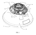
- FIG. 1 shows one example of an airborne vehicle, such as CM 10, and an attachment/deceleration system which allows for angular adjustment of the CM during aerial decent.
- the CM 10 includes a blunt base 12 with a heat shield (not shown) for re-entry.
- a support structure 18, to be described in greater detail subsequently, is integrated into the CM 10 at a forward bulkhead 20.
- a handle 22 may be attached to the support structure 18 with hinges 24.
- An attachment plate 26 may be located at or near the center of the handle 22 for attachment of risers or cables 28 that attach to one or more parachutes or a similar type device used to decelerate the CM during retry and recovery.
- the undeployed parachute system may be stored in various containers 29a - 29c arranged in the nose of the CM 10.
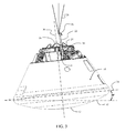
- the risers 28 of the parachute system (not shown), which may comprise one or more parachutes and generally referred to herein as the "parachute" are attached to the handle 22 in an unrotated position.
- the offset position of the attachment plate 26 with respect to a central axis 30 of the CM 10 results in the CM 10 being suspended from the risers 28 with a first deck angle of nominally 37° between a horizontal reference 32 and a reference station plane 34 for the example embodiment shown.
- the CM 10 may undergo a water landing or provide the desired deck angle for other operational considerations.
- handle 22 may be released for rotation about hinges 24.
- handle 22 is oriented in a rotated position that is substantially vertically or parallel to the CM central axis 30. Rotation of the handle 22 may be limited by dampers 36, to be described in greater detail subsequently.
- the hinges 24 are laterally displaced from the axis 30 on the support structure 18.
- this nominal displacement induces a hang angle due to a center of gravity offset which in turn provides a suspended second deck angle of approximately 10° between the horizontal baseline 32 and the reference station plane 34.
- the offset of the handle 22 and support structure 18 precludes undesired impact on or interference with the docking mechanism 16.
- a relatively more central or symmetrical configuration of the handle 22 and support structure 18 may be desired.
- Specific desired hang angles may also be obtained by limiting rotation of the handle 22 using a controlled release of the damper 36, and intermediate stops between the initial 37° deck angle and the ultimate 10° deck angle.
- a center of gravity that is off-axis from the central axis 30 will result in an off-axis hang angle that may be sustained or altered by placement of the locations of the hinges 24 or rotation angle of the handle 22.
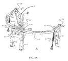
- Support structure 18 incorporates vertical hinge fittings 38 which are attached at a bottom flange 40 to the forward bulkhead 20.
- Hinges 24 are supported in clevises 42 extending from the hinge fittings 38 distal from the bottom flanges 40.
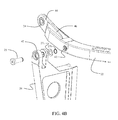
- Hinges 24 may be spherical bearings or similar rotational support elements engaged by pivot pins 25 inserted through the clevises and retained by washers 27a and clips 27b as shown in detail in FIG. 4B .
- Handle 22 which is also shown in additional detail in FIGs.
- 5A and 5B may have an arcuate shape for the example embodiment but may be of alternative geometric shapes in other embodiments as may be required to accommodate structural loads or overall CM geometry such as a single hinged rod, a triangular handle, a rectangular or other multilateral handle.
- Tangs 44 extend from terminal ends 46 of the handle 22 to support the hinge elements and are received in the clevises 42.
- an attachment plate 26 is provided for attachment of the risers 28.
- the handle 22 is engaged at or near the central portion 48 by a support bracket 52 that extends from the forward bulkhead 20.
- the central portion 48 of the handle 22 is constrained to the support bracket 52 using separation assemblies such as pins or bolts 54 secured with handle release separation nuts.
- the separation assemblies may be mechanical or pyrotechnic and provide a controllable mechanism to release the handle 22 from the support bracket 52 for rotation to the extended position show in FIGs. 5A and 5B (and FIG. 2 ).
- two 3 ⁇ 4 inch pyrotechnic separation bolts were employed to secure and release the handle 22.
- a drogue attach fitting 58 is also attached to the support bracket 52 providing an attach point for drogue shroud lines 57 (seen in FIG. 1 ) proximate the attachment plate 26.
- Canisters 59a and 59b are provided in the nose of the CM in a manner comparable to the containers 29a-29c.
- the handle 22 incorporates a dog leg geometry allowing an offset from a neutral plane 60 extending through the hinges 24 and attachment plate 26 for attachment bosses 62 to connect dampers 36 (seen in FIG. 4A ).
- the dog leg angle 66 allows alignment of an upper portion 64 of the handle 22 parallel to the central axis 30 in the deployed condition or for other adjustment of desired hang angle or requirements of deployment dynamics.
- the dampers 36 in certain embodiments may be mechanical, hydraulic or pneumatic shock absorbers 68 as shown in FIG. 6 .
- the shock absorbers 68 extend from the forward bulkhead 20 for connection at the attachment bosses 62 on handle 22.
- the shock absorbers 68 may be adjustable or actively controllable for extension length to limit rotation of the handle 22 at desired angles for altering the hang angle of the CM 10 during descent and landing.
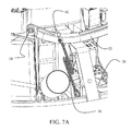
- dampers 36 may be an extendible strap 70 connected from the forward bulkhead 20 to the attachment bosses 62 as shown in FIG. 7A .
- the straps 70 may be folded and secured with frangible bands or other means for compact storage with the handle 22 in the unrotated position. Upon release of the separation assemblies allowing the handle 22 to rotate about the hinges 24 to the extended position, the straps 70 extend and limit (dampen) rotation of the handle as shown in FIG. 7B .
- the straps 70 may be of a textile material fabricated from aramid fiber materials such as Kevlar®, liquid crystal polymer fiber materials such as Vectran®, Nylon or comparable materials.
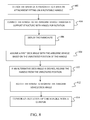
- the embodiments described provide a method for altering a hang angle of an airborne vehicle such as a CM 10 suspended by risers for a parachute descent and landing as shown in
- FIG. 8 The risers 28 of a parachute are attached to an attachment plate 26 disposed on a handle 22, step 802.
- the handle 22 is connected to the airborne vehicle through a support structure 18 with hinges 24 for rotation of the handle 24, step 804.
- the airborne vehicle Upon deploying the parachute, step 806, the airborne vehicle assumes a first deck angle based on the unrotated position of the handle 22, step 808. If an alternative deck angle is desired, release assemblies such as pyrotechnically actuated bolts 54 are employed to release the handle 22 from the unrotated position, step 810.
- the handle 22 then rotates to reorient the airborne vehicle deck angle, step 812. Rotation of the handle 22 may be constrained with a damper 36, step 814.
Landscapes
- Engineering & Computer Science (AREA)
- Remote Sensing (AREA)
- Aviation & Aerospace Engineering (AREA)
- Aiming, Guidance, Guns With A Light Source, Armor, Camouflage, And Targets (AREA)
- Toys (AREA)
Abstract
Description
- Embodiments of the disclosure relate generally to the field of aerodynamic deceleration systems for airborne vehicles, and more particularly to a system and method for a selectable alignment angle for aerial descent and landing of an airborne vehicle.
- Reentering spacecraft which are not aerodynamically configured and controlled are typically recovered using aerodynamic deceleration and landing parachutes. Mercury, Gemini and Apollo spacecraft all employed this form of recovery system that includes an attachment of parachute risers to a fixed point on the spacecraft. However, in certain cases it may be desirable to have differing angular presentation of the spacecraft during descent and/or prior to landing to accommodate such issues as water versus hard surface landing conditions.
- It is therefore desirable to provide an attachment system for parachute risers which allows angular adjustment of the spacecraft orientation.
- Embodiments disclosed herein provide an apparatus for reorientation of an airborne vehicle during decent employing a handle rotatably attached to the airborne vehicle and connected to a parachute. Once the parachute is deployed, rotation of the handle reorients a deck angle of the airborne vehicle with respect to the parachute.
- In one embodiment, a command module (CM) includes a parachute attachment system that employs a handle rotatably attached to the CM. The handle has an unrotated position and a rotated position and a suspended deck angle of the CM is altered between the unrotated and rotated position. An attachment plate on the handle attaches to risers of a parachute and at least one release assembly is operable to release the handle from the unrotated position to the rotated position.
- The embodiments provide a method of reorientation of an airborne vehicle during descent through attachment of a parachute to a rotatable handle connected to the airborne vehicle. The parachute is then deployed and, if an alternative deck angle is desired, the handle is rotated to reorient the airborne vehicle deck angle.
- The features, functions, and advantages that have been discussed can be achieved independently in various embodiments of the present disclosure or may be combined in yet other embodiments further details of which can be seen with reference to the following description and drawings.
-
-
FIG. 1 is a isometric view of an example spacecraft on which the disclosed embodiments may be employed; -
FIG. 2 is a side view of the spacecraft suspended from risers with a handle in the initial unrotated position; -
FIG. 3 is a side view of the spacecraft suspended from risers with the handle ofFIG. 2 in the rotated position for reduced deck angle; -
FIG. 4A is a detailed isometric view of a support structure and handle according to one embodiment; -
FIG. 4B is a detailed exploded partial isometric view of the elements of hinges according to one embodiment; -
FIG. 5A is a front view of the handle; -
FIG. 5B is a side view of the handle; -
FIG. 6 is a pictorial view of a damper according to one embodiment; -
FIG. 7A is a pictorial view of a damper and handle in an unrotated configuration according to one embodiment; -
FIG. 7B is a pictorial view of the damper and handle ofFIG. 7B in a rotated configuration; and, -
FIG. 8 is a flow chart showing a method for adjustment of hang angle of an airborne vehicle such as the example spacecraft. - Embodiments disclosed herein provide a mechanism that allows for the reorientation of an airborne vehicle or load such as a reentering spacecraft, shuttle, command module (CM), or cargo using a parachute or similar type deceleration method to allow for landing on land or water. A handle having a structure for parachute attachment is attached to the CM with hinges and may be stowed and locked down under a thermal protection cover using a support structure that carries the parachute opening loads. The handle is fastened to the CM in the stowed unrotated condition using separation nuts. After parachute deployment the handle is rotatable about the hinges to reorient the capsule under one or more parachutes to provide a nearly flat deck angle. Dual mode operation is enabled since the handle may be left in the stowed configuration (high hang angle) for water landings (similar to Apollo), or rotated about the hinges to create the flat or nearly flat hang angle for land landing operations. The handle further simplifies the parachute riser line routing and management of those cables during deployment.
- The release of the handle for rotation may be achieved by actuating separation nuts that secure the handle to the CM. When the handle is released, the handle is allowed to rotate freely about the hinges and rotation of the handle may be limited by a damper to prevent over rotating.
-
FIG. 1 shows one example of an airborne vehicle, such asCM 10, and an attachment/deceleration system which allows for angular adjustment of the CM during aerial decent. TheCM 10 includes ablunt base 12 with a heat shield (not shown) for re-entry. Anose 14 of theCM 10, shown with the thermal cover removed for clarity, houses various systems including an exit ordocking mechanism 16. Asupport structure 18, to be described in greater detail subsequently, is integrated into theCM 10 at aforward bulkhead 20. In one embodiment, ahandle 22 may be attached to thesupport structure 18 with hinges 24. Anattachment plate 26 may be located at or near the center of thehandle 22 for attachment of risers orcables 28 that attach to one or more parachutes or a similar type device used to decelerate the CM during retry and recovery. The undeployed parachute system may be stored invarious containers 29a - 29c arranged in the nose of theCM 10. - As shown in
FIG. 2 , when initially deployed therisers 28 of the parachute system (not shown), which may comprise one or more parachutes and generally referred to herein as the "parachute", are attached to thehandle 22 in an unrotated position. The offset position of theattachment plate 26 with respect to acentral axis 30 of theCM 10 results in theCM 10 being suspended from therisers 28 with a first deck angle of nominally 37° between ahorizontal reference 32 and areference station plane 34 for the example embodiment shown. In this configuration theCM 10 may undergo a water landing or provide the desired deck angle for other operational considerations. - As shown in
FIG. 3 , if desired to accommodate a landing of the CM on land (hard surface) or for differing operational considerations a lower deck angle is desired, handle 22 may be released for rotation about hinges 24. In this regard, handle 22 is oriented in a rotated position that is substantially vertically or parallel to the CMcentral axis 30. Rotation of thehandle 22 may be limited bydampers 36, to be described in greater detail subsequently. In the example embodiment shown inFIGs. 1-3 , thehinges 24 are laterally displaced from theaxis 30 on thesupport structure 18. In the unattached or deployed position, this nominal displacement induces a hang angle due to a center of gravity offset which in turn provides a suspended second deck angle of approximately 10° between thehorizontal baseline 32 and thereference station plane 34. For the embodiment shown, the offset of thehandle 22 andsupport structure 18 precludes undesired impact on or interference with thedocking mechanism 16. In alternative embodiments, a relatively more central or symmetrical configuration of thehandle 22 andsupport structure 18 may be desired. Specific desired hang angles may also be obtained by limiting rotation of thehandle 22 using a controlled release of thedamper 36, and intermediate stops between the initial 37° deck angle and the ultimate 10° deck angle. Additionally, a center of gravity that is off-axis from thecentral axis 30 will result in an off-axis hang angle that may be sustained or altered by placement of the locations of thehinges 24 or rotation angle of thehandle 22. - Details of the
support structure 18, thehandle 22, and thehinges 24 are shown inFIG. 4A .Support structure 18 incorporatesvertical hinge fittings 38 which are attached at abottom flange 40 to theforward bulkhead 20.Hinges 24 are supported inclevises 42 extending from thehinge fittings 38 distal from thebottom flanges 40.Hinges 24 may be spherical bearings or similar rotational support elements engaged bypivot pins 25 inserted through the clevises and retained bywashers 27a and clips 27b as shown in detail inFIG. 4B .Handle 22, which is also shown in additional detail inFIGs. 5A and 5B , may have an arcuate shape for the example embodiment but may be of alternative geometric shapes in other embodiments as may be required to accommodate structural loads or overall CM geometry such as a single hinged rod, a triangular handle, a rectangular or other multilateral handle.Tangs 44 extend from terminal ends 46 of thehandle 22 to support the hinge elements and are received in theclevises 42. On or near acentral portion 48 of the handle, anattachment plate 26 is provided for attachment of therisers 28. - In the unrotated or stored position as shown in
FIG. 4A (andFIG. 3 ), thehandle 22 is engaged at or near thecentral portion 48 by asupport bracket 52 that extends from theforward bulkhead 20. For the example embodiment, thecentral portion 48 of thehandle 22 is constrained to thesupport bracket 52 using separation assemblies such as pins orbolts 54 secured with handle release separation nuts. The separation assemblies may be mechanical or pyrotechnic and provide a controllable mechanism to release thehandle 22 from thesupport bracket 52 for rotation to the extended position show inFIGs. 5A and 5B (andFIG. 2 ). In one example embodiment, two ¾ inch pyrotechnic separation bolts were employed to secure and release thehandle 22. For the embodiment shown a drogue attach fitting 58 is also attached to thesupport bracket 52 providing an attach point for drogue shroud lines 57 (seen inFIG. 1 ) proximate theattachment plate 26.Canisters FIG. 1 ) for storage of the drogue chutes are provided in the nose of the CM in a manner comparable to thecontainers 29a-29c. - For the example embodiment shown in
FIG. 5B , thehandle 22 incorporates a dog leg geometry allowing an offset from aneutral plane 60 extending through thehinges 24 andattachment plate 26 forattachment bosses 62 to connect dampers 36 (seen inFIG. 4A ). Thedog leg angle 66 allows alignment of anupper portion 64 of thehandle 22 parallel to thecentral axis 30 in the deployed condition or for other adjustment of desired hang angle or requirements of deployment dynamics. - The
dampers 36 in certain embodiments may be mechanical, hydraulic orpneumatic shock absorbers 68 as shown inFIG. 6 . Theshock absorbers 68 extend from theforward bulkhead 20 for connection at theattachment bosses 62 onhandle 22. Theshock absorbers 68 may be adjustable or actively controllable for extension length to limit rotation of thehandle 22 at desired angles for altering the hang angle of theCM 10 during descent and landing. In alternative embodiments, as for the primary example shown in the other drawings,dampers 36 may be anextendible strap 70 connected from theforward bulkhead 20 to theattachment bosses 62 as shown inFIG. 7A . - For the embodiment of
FIG. 7A , thestraps 70 may be folded and secured with frangible bands or other means for compact storage with thehandle 22 in the unrotated position. Upon release of the separation assemblies allowing thehandle 22 to rotate about thehinges 24 to the extended position, thestraps 70 extend and limit (dampen) rotation of the handle as shown inFIG. 7B . In one embodiment, thestraps 70 may be of a textile material fabricated from aramid fiber materials such as Kevlar®, liquid crystal polymer fiber materials such as Vectran®, Nylon or comparable materials. - The embodiments described provide a method for altering a hang angle of an airborne vehicle such as a
CM 10 suspended by risers for a parachute descent and landing as shown in -
FIG. 8 . Therisers 28 of a parachute are attached to anattachment plate 26 disposed on ahandle 22,step 802. Thehandle 22 is connected to the airborne vehicle through asupport structure 18 withhinges 24 for rotation of thehandle 24,step 804. Upon deploying the parachute,step 806, the airborne vehicle assumes a first deck angle based on the unrotated position of thehandle 22,step 808. If an alternative deck angle is desired, release assemblies such as pyrotechnically actuatedbolts 54 are employed to release thehandle 22 from the unrotated position,step 810. Thehandle 22 then rotates to reorient the airborne vehicle deck angle,step 812. Rotation of thehandle 22 may be constrained with adamper 36,step 814. - Further, the disclosure comprises embodiments according to the following clauses:
- Clause 1. An apparatus for reorientation of an airborne vehicle during descent comprising a handle, the handle being rotatably attached to an airborne vehicle and connected to a parachute,
wherein rotation of the handle upon deployment to a rotated position reorients a deck angle of the airborne vehicle. - Clause 2. The apparatus of clause 1 further comprising an attachment plate on the handle for attachment of risers to the parachute.
- Clause 3. The apparatus of clause 1 or 2 further comprising:
- at least one hinge rotatably connecting the handle to the airborne vehicle for rotation of the handle from an unrotated position to the rotated position.
- Clause 4. The apparatus of clause 1, 2 or 3 further comprising at least one damper connected between the handle and the airborne vehicle to limit rotation of the handle.
- Clause 5. A parachute attachment system comprising:
- a handle rotatably attached to an airborne vehicle and having an unrotated position and a rotated position;
- a riser attachment fitting on the handle for attachment of parachute risers; and,
- at least one release assembly operable to release the handle from the unrotated position to the rotated position,
- wherein a suspended deck angle of the airborne vehicle is altered upon rotation of the handle between the unrotated and rotated position.
- Clause 6. The parachute attachment system of clause 5 further comprising:
- a support structure attached to the airborne vehicle; and,
- at least one hinge interconnecting the handle to the support structure for rotation of the handle from the unrotated position to the rotated position.
- Clause 7. The parachute attachment system of clause 5 or 6 further comprising:
- at least one damper connected between the handle and the air vehicle to limit rotation of the handle.
- Clause 8. The parachute attachment system of clause 7 wherein the damper is a mechanical, pneumatic or hydraulic shock absorber.
- Clause 9. The parachute attachment system of clause 7 wherein the damper is a textile strap.
-
Clause 10. The parachute attachment system of clause 9 wherein the textile strap is folded and constrained with frangible bands with the handle in the unrotated position. - Clause 11. The parachute attachment system of any one of clauses 5 to 10 wherein the handle is arcuate.
-
Clause 12. The parachute attachment system of any one of clauses 7 to 10 wherein the handle is a dog leg configuration having an attachment boss for the damper. - Clause 13. The parachute attachment system of
clause 1 or 12 wherein an angle of the dog leg aligns an upper portion of the handle parallel to a central axis of the airborne vehicle. -
Clause 14. The parachute attachment system of any one of clauses 5 to 13 wherein the unrotated position of the handle provides a first deck angle for water landing and the rotated position of the handle provide a second deck angle for surface landing. - Clause 15. A method of reorientation of an airborne vehicle during parachute descent comprising:
- attaching a parachute to a rotatable handle connecting to an airborne vehicle having a first deck angle;
- deploying the parachute; and
- rotating the handle to reorient the airborne vehicle to a second deck angle.
-
Clause 16. The method of clause 15 further comprising attaching the rotatable handle to the airborne vehicle with hinges in a support assembly mounted to the airborne vehicle. - Clause 17. The method of
clause 15 or 16 further comprising assuming an initial deck angle with the handle in an unrotated position. -
Clause 18. The method ofclause 15, 16 or 17 further comprising constraining the rotation of the handle with a damper. - Clause 19. The method of any one of clauses 15 to 18 wherein the step of rotating the handle includes selectively releasing the handle from an unrotated position using release assemblies to alter the deck angle of the airborne vehicle.
- Having now described various embodiments of the disclosure in detail as required by the patent statutes, those skilled in the art will recognize modifications and substitutions to the specific embodiments disclosed herein. Such modifications are within the scope and intent of the present disclosure as defined in the following claims.
Claims (14)
- An apparatus for reorientation of an airborne vehicle during descent comprising a handle, the handle being rotatably attached to an airborne vehicle and connected to a parachute,
wherein rotation of the handle upon deployment to a rotated position reorients a deck angle of the airborne vehicle. - The apparatus of claim 1 further comprising an attachment plate on the handle for attachment of risers to the parachute.
- The apparatus of claim 1 or 2 further comprising:at least one hinge rotatably connecting the handle to the airborne vehicle for rotation of the handle from an unrotated position to the rotated position.
- The apparatus of claim 1, 2 or 3 further comprising at least one damper connected between the handle and the airborne vehicle to limit rotation of the handle.
- A parachute attachment system comprising:a handle rotatably attached to an airborne vehicle and having an unrotated position and a rotated position;a riser attachment fitting on the handle for attachment of parachute risers; and,at least one release assembly operable to release the handle from the unrotated position to the rotated position,wherein a suspended deck angle of the airborne vehicle is altered upon rotation of the handle between the unrotated and rotated position.
- The parachute attachment system of claim 5 further comprising:a support structure attached to the airborne vehicle; and,at least one hinge interconnecting the handle to the support structure for rotation of the handle from the unrotated position to the rotated position.
- The parachute attachment system of claim 5 or 6 further comprising:at least one damper connected between the handle and the air vehicle to limit rotation of the handle.
- The parachute attachment system of claim 7 wherein the damper is a mechanical, pneumatic or hydraulic shock absorber.
- The parachute attachment system of claim 7 wherein the damper is a textile strap.
- The parachute attachment system of claim 9 wherein the textile strap is folded and constrained with frangible bands with the handle in the unrotated position.
- The parachute attachment system of any one of claims 5 to 9 wherein the handle is arcuate.
- The parachute attachment system of claim 7 to 10 wherein the handle is a dog leg configuration having an attachment boss for the damper.
- The parachute attachment system of claim 12 wherein an angle of the dog leg aligns an upper portion of the handle parallel to a central axis of the airborne vehicle.
- The parachute attachment system of any one of claims 5 to 13 wherein the unrotated position of the handle provides a first deck angle for water landing and the rotated position of the handle provide a second deck angle for surface landing.
Applications Claiming Priority (1)
| Application Number | Priority Date | Filing Date | Title |
|---|---|---|---|
| US13/848,215 US8950709B2 (en) | 2013-03-21 | 2013-03-21 | Handle for dual mode airborne vehicle landing |
Publications (3)
| Publication Number | Publication Date |
|---|---|
| EP2781455A2 true EP2781455A2 (en) | 2014-09-24 |
| EP2781455A3 EP2781455A3 (en) | 2015-06-17 |
| EP2781455B1 EP2781455B1 (en) | 2017-01-04 |
Family
ID=50238101
Family Applications (1)
| Application Number | Title | Priority Date | Filing Date |
|---|---|---|---|
| EP14155852.8A Active EP2781455B1 (en) | 2013-03-21 | 2014-02-19 | Handle for dual mode airborne vehicle landing |
Country Status (3)
| Country | Link |
|---|---|
| US (1) | US8950709B2 (en) |
| EP (1) | EP2781455B1 (en) |
| CA (1) | CA2841492C (en) |
Cited By (1)
| Publication number | Priority date | Publication date | Assignee | Title |
|---|---|---|---|---|
| CN106742080A (en) * | 2017-02-16 | 2017-05-31 | 南京航空航天大学 | One kind buffering/integrated the lander of walking |
Families Citing this family (3)
| Publication number | Priority date | Publication date | Assignee | Title |
|---|---|---|---|---|
| US20150008287A1 (en) * | 2013-06-11 | 2015-01-08 | Pavlos Dem. Giannakopoulos | Spacecraft's parachutes with straps for compensating the oscillations |
| US11390382B1 (en) * | 2019-07-08 | 2022-07-19 | United States Of America As Represented By The Secretary Of The Air Force | Delivery system for unmanned aerial vehicles |
| CN120773939B (en) * | 2025-08-21 | 2025-12-23 | 中国科学院国家空间科学中心 | A highly adaptive landing slow-release device |
Family Cites Families (4)
| Publication number | Priority date | Publication date | Assignee | Title |
|---|---|---|---|---|
| US1233087A (en) * | 1916-11-18 | 1917-07-10 | John A Maclean | Parachute. |
| US4108402A (en) * | 1977-01-13 | 1978-08-22 | Eleanor J. Bowen | Aircraft emergency letdown system |
| FR2645474B1 (en) * | 1989-04-11 | 1991-06-07 | David Jean Pierre | DEVICE FOR TRANSFORMING A MOTORCYCLE INTO AN ULTRA-LIGHT MOTORIZED AIRCRAFT |
| US5505407A (en) * | 1993-09-09 | 1996-04-09 | Fran Rich Chi Associates | Air-land vehicle |
-
2013
- 2013-03-21 US US13/848,215 patent/US8950709B2/en active Active
-
2014
- 2014-02-03 CA CA2841492A patent/CA2841492C/en active Active
- 2014-02-19 EP EP14155852.8A patent/EP2781455B1/en active Active
Cited By (1)
| Publication number | Priority date | Publication date | Assignee | Title |
|---|---|---|---|---|
| CN106742080A (en) * | 2017-02-16 | 2017-05-31 | 南京航空航天大学 | One kind buffering/integrated the lander of walking |
Also Published As
| Publication number | Publication date |
|---|---|
| EP2781455A3 (en) | 2015-06-17 |
| CA2841492C (en) | 2016-05-10 |
| US8950709B2 (en) | 2015-02-10 |
| EP2781455B1 (en) | 2017-01-04 |
| US20140284427A1 (en) | 2014-09-25 |
| CA2841492A1 (en) | 2014-09-21 |
Similar Documents
| Publication | Publication Date | Title |
|---|---|---|
| US11608181B2 (en) | Rigidized assisted opening system for high altitude parafoils | |
| CA2841492C (en) | Handle for dual mode airborne vehicle landing | |
| US10112721B2 (en) | Parachute deployment system for an unmanned aerial vehicle | |
| US20170225792A1 (en) | Parachute deployment system for an unmanned aerial vehicle | |
| US4993665A (en) | Device for attachment to a helicopter | |
| US11591111B2 (en) | Apparatus for vehicle launch, recovery, storage and transport | |
| KR20130081275A (en) | Mobile aircraft recovery system | |
| EP2872400B1 (en) | Parachute device | |
| US4108402A (en) | Aircraft emergency letdown system | |
| WO2016081324A1 (en) | Enveloping aerodynamic accelerator | |
| US4040583A (en) | Methods and apparatus for effecting recovery of a high speed aircraft from a condition of incipient or developed spin | |
| WO2024226793A2 (en) | Deployable landing gear systems | |
| US3107887A (en) | Aircraft safety system | |
| WO2009083953A2 (en) | Imaging system and method | |
| EP1575829B1 (en) | Skyhook reserve parachute deployment system | |
| US20220388657A1 (en) | Modular load carrying apparatus with a carrier star | |
| WO2009048666A2 (en) | Air launch and recovery pylon | |
| US4496122A (en) | Extended moment arm anti-spin device | |
| US3301511A (en) | Wing deployment method and apparatus | |
| US20050087652A1 (en) | Emergency parachute system for helicopters | |
| Smith et al. | Development of the NASA X-38 parafoil landing system | |
| CA3146214C (en) | A modular load carrying apparatus with interchangeable platforms | |
| JP2002037199A (en) | Holding mechanism | |
| CN119240042A (en) | A special-shaped umbrella cabin device and an umbrella system partition installation and use method | |
| Taylor et al. | A Review of the MLAS Parachute Systems |
Legal Events
| Date | Code | Title | Description |
|---|---|---|---|
| PUAI | Public reference made under article 153(3) epc to a published international application that has entered the european phase |
Free format text: ORIGINAL CODE: 0009012 |
|
| 17P | Request for examination filed |
Effective date: 20140219 |
|
| AK | Designated contracting states |
Kind code of ref document: A2 Designated state(s): AL AT BE BG CH CY CZ DE DK EE ES FI FR GB GR HR HU IE IS IT LI LT LU LV MC MK MT NL NO PL PT RO RS SE SI SK SM TR |
|
| AX | Request for extension of the european patent |
Extension state: BA ME |
|
| PUAL | Search report despatched |
Free format text: ORIGINAL CODE: 0009013 |
|
| AK | Designated contracting states |
Kind code of ref document: A3 Designated state(s): AL AT BE BG CH CY CZ DE DK EE ES FI FR GB GR HR HU IE IS IT LI LT LU LV MC MK MT NL NO PL PT RO RS SE SI SK SM TR |
|
| AX | Request for extension of the european patent |
Extension state: BA ME |
|
| RIC1 | Information provided on ipc code assigned before grant |
Ipc: B64G 1/62 20060101AFI20150512BHEP Ipc: B64D 17/80 20060101ALI20150512BHEP |
|
| GRAP | Despatch of communication of intention to grant a patent |
Free format text: ORIGINAL CODE: EPIDOSNIGR1 |
|
| INTG | Intention to grant announced |
Effective date: 20160902 |
|
| GRAS | Grant fee paid |
Free format text: ORIGINAL CODE: EPIDOSNIGR3 |
|
| STAA | Information on the status of an ep patent application or granted ep patent |
Free format text: STATUS: GRANT OF PATENT IS INTENDED |
|
| GRAA | (expected) grant |
Free format text: ORIGINAL CODE: 0009210 |
|
| STAA | Information on the status of an ep patent application or granted ep patent |
Free format text: STATUS: THE PATENT HAS BEEN GRANTED |
|
| AK | Designated contracting states |
Kind code of ref document: B1 Designated state(s): AL AT BE BG CH CY CZ DE DK EE ES FI FR GB GR HR HU IE IS IT LI LT LU LV MC MK MT NL NO PL PT RO RS SE SI SK SM TR |
|
| REG | Reference to a national code |
Ref country code: GB Ref legal event code: FG4D |
|
| REG | Reference to a national code |
Ref country code: CH Ref legal event code: EP |
|
| REG | Reference to a national code |
Ref country code: AT Ref legal event code: REF Ref document number: 858968 Country of ref document: AT Kind code of ref document: T Effective date: 20170115 |
|
| REG | Reference to a national code |
Ref country code: IE Ref legal event code: FG4D |
|
| REG | Reference to a national code |
Ref country code: DE Ref legal event code: R096 Ref document number: 602014005924 Country of ref document: DE Ref country code: FR Ref legal event code: PLFP Year of fee payment: 4 |
|
| REG | Reference to a national code |
Ref country code: LT Ref legal event code: MG4D Ref country code: NL Ref legal event code: MP Effective date: 20170104 |
|
| PG25 | Lapsed in a contracting state [announced via postgrant information from national office to epo] |
Ref country code: BE Free format text: LAPSE BECAUSE OF NON-PAYMENT OF DUE FEES Effective date: 20170228 |
|
| REG | Reference to a national code |
Ref country code: AT Ref legal event code: MK05 Ref document number: 858968 Country of ref document: AT Kind code of ref document: T Effective date: 20170104 |
|
| PG25 | Lapsed in a contracting state [announced via postgrant information from national office to epo] |
Ref country code: NL Free format text: LAPSE BECAUSE OF FAILURE TO SUBMIT A TRANSLATION OF THE DESCRIPTION OR TO PAY THE FEE WITHIN THE PRESCRIBED TIME-LIMIT Effective date: 20170104 |
|
| PG25 | Lapsed in a contracting state [announced via postgrant information from national office to epo] |
Ref country code: LT Free format text: LAPSE BECAUSE OF FAILURE TO SUBMIT A TRANSLATION OF THE DESCRIPTION OR TO PAY THE FEE WITHIN THE PRESCRIBED TIME-LIMIT Effective date: 20170104 Ref country code: GR Free format text: LAPSE BECAUSE OF FAILURE TO SUBMIT A TRANSLATION OF THE DESCRIPTION OR TO PAY THE FEE WITHIN THE PRESCRIBED TIME-LIMIT Effective date: 20170405 Ref country code: NO Free format text: LAPSE BECAUSE OF FAILURE TO SUBMIT A TRANSLATION OF THE DESCRIPTION OR TO PAY THE FEE WITHIN THE PRESCRIBED TIME-LIMIT Effective date: 20170404 Ref country code: FI Free format text: LAPSE BECAUSE OF FAILURE TO SUBMIT A TRANSLATION OF THE DESCRIPTION OR TO PAY THE FEE WITHIN THE PRESCRIBED TIME-LIMIT Effective date: 20170104 Ref country code: IS Free format text: LAPSE BECAUSE OF FAILURE TO SUBMIT A TRANSLATION OF THE DESCRIPTION OR TO PAY THE FEE WITHIN THE PRESCRIBED TIME-LIMIT Effective date: 20170504 Ref country code: HR Free format text: LAPSE BECAUSE OF FAILURE TO SUBMIT A TRANSLATION OF THE DESCRIPTION OR TO PAY THE FEE WITHIN THE PRESCRIBED TIME-LIMIT Effective date: 20170104 |
|
| PG25 | Lapsed in a contracting state [announced via postgrant information from national office to epo] |
Ref country code: RS Free format text: LAPSE BECAUSE OF FAILURE TO SUBMIT A TRANSLATION OF THE DESCRIPTION OR TO PAY THE FEE WITHIN THE PRESCRIBED TIME-LIMIT Effective date: 20170104 Ref country code: BG Free format text: LAPSE BECAUSE OF FAILURE TO SUBMIT A TRANSLATION OF THE DESCRIPTION OR TO PAY THE FEE WITHIN THE PRESCRIBED TIME-LIMIT Effective date: 20170404 Ref country code: PT Free format text: LAPSE BECAUSE OF FAILURE TO SUBMIT A TRANSLATION OF THE DESCRIPTION OR TO PAY THE FEE WITHIN THE PRESCRIBED TIME-LIMIT Effective date: 20170504 Ref country code: LV Free format text: LAPSE BECAUSE OF FAILURE TO SUBMIT A TRANSLATION OF THE DESCRIPTION OR TO PAY THE FEE WITHIN THE PRESCRIBED TIME-LIMIT Effective date: 20170104 Ref country code: ES Free format text: LAPSE BECAUSE OF FAILURE TO SUBMIT A TRANSLATION OF THE DESCRIPTION OR TO PAY THE FEE WITHIN THE PRESCRIBED TIME-LIMIT Effective date: 20170104 Ref country code: PL Free format text: LAPSE BECAUSE OF FAILURE TO SUBMIT A TRANSLATION OF THE DESCRIPTION OR TO PAY THE FEE WITHIN THE PRESCRIBED TIME-LIMIT Effective date: 20170104 Ref country code: AT Free format text: LAPSE BECAUSE OF FAILURE TO SUBMIT A TRANSLATION OF THE DESCRIPTION OR TO PAY THE FEE WITHIN THE PRESCRIBED TIME-LIMIT Effective date: 20170104 Ref country code: SE Free format text: LAPSE BECAUSE OF FAILURE TO SUBMIT A TRANSLATION OF THE DESCRIPTION OR TO PAY THE FEE WITHIN THE PRESCRIBED TIME-LIMIT Effective date: 20170104 |
|
| REG | Reference to a national code |
Ref country code: CH Ref legal event code: PL |
|
| REG | Reference to a national code |
Ref country code: DE Ref legal event code: R097 Ref document number: 602014005924 Country of ref document: DE |
|
| PG25 | Lapsed in a contracting state [announced via postgrant information from national office to epo] |
Ref country code: IT Free format text: LAPSE BECAUSE OF FAILURE TO SUBMIT A TRANSLATION OF THE DESCRIPTION OR TO PAY THE FEE WITHIN THE PRESCRIBED TIME-LIMIT Effective date: 20170104 Ref country code: CH Free format text: LAPSE BECAUSE OF NON-PAYMENT OF DUE FEES Effective date: 20170228 Ref country code: SK Free format text: LAPSE BECAUSE OF FAILURE TO SUBMIT A TRANSLATION OF THE DESCRIPTION OR TO PAY THE FEE WITHIN THE PRESCRIBED TIME-LIMIT Effective date: 20170104 Ref country code: CZ Free format text: LAPSE BECAUSE OF FAILURE TO SUBMIT A TRANSLATION OF THE DESCRIPTION OR TO PAY THE FEE WITHIN THE PRESCRIBED TIME-LIMIT Effective date: 20170104 Ref country code: EE Free format text: LAPSE BECAUSE OF FAILURE TO SUBMIT A TRANSLATION OF THE DESCRIPTION OR TO PAY THE FEE WITHIN THE PRESCRIBED TIME-LIMIT Effective date: 20170104 Ref country code: RO Free format text: LAPSE BECAUSE OF FAILURE TO SUBMIT A TRANSLATION OF THE DESCRIPTION OR TO PAY THE FEE WITHIN THE PRESCRIBED TIME-LIMIT Effective date: 20170104 Ref country code: LI Free format text: LAPSE BECAUSE OF NON-PAYMENT OF DUE FEES Effective date: 20170228 |
|
| PLBE | No opposition filed within time limit |
Free format text: ORIGINAL CODE: 0009261 |
|
| STAA | Information on the status of an ep patent application or granted ep patent |
Free format text: STATUS: NO OPPOSITION FILED WITHIN TIME LIMIT |
|
| REG | Reference to a national code |
Ref country code: IE Ref legal event code: MM4A |
|
| PG25 | Lapsed in a contracting state [announced via postgrant information from national office to epo] |
Ref country code: MC Free format text: LAPSE BECAUSE OF FAILURE TO SUBMIT A TRANSLATION OF THE DESCRIPTION OR TO PAY THE FEE WITHIN THE PRESCRIBED TIME-LIMIT Effective date: 20170104 Ref country code: SM Free format text: LAPSE BECAUSE OF FAILURE TO SUBMIT A TRANSLATION OF THE DESCRIPTION OR TO PAY THE FEE WITHIN THE PRESCRIBED TIME-LIMIT Effective date: 20170104 Ref country code: DK Free format text: LAPSE BECAUSE OF FAILURE TO SUBMIT A TRANSLATION OF THE DESCRIPTION OR TO PAY THE FEE WITHIN THE PRESCRIBED TIME-LIMIT Effective date: 20170104 |
|
| PG25 | Lapsed in a contracting state [announced via postgrant information from national office to epo] |
Ref country code: LU Free format text: LAPSE BECAUSE OF NON-PAYMENT OF DUE FEES Effective date: 20170219 |
|
| REG | Reference to a national code |
Ref country code: BE Ref legal event code: MM Effective date: 20170228 |
|
| REG | Reference to a national code |
Ref country code: FR Ref legal event code: PLFP Year of fee payment: 5 |
|
| PG25 | Lapsed in a contracting state [announced via postgrant information from national office to epo] |
Ref country code: SI Free format text: LAPSE BECAUSE OF FAILURE TO SUBMIT A TRANSLATION OF THE DESCRIPTION OR TO PAY THE FEE WITHIN THE PRESCRIBED TIME-LIMIT Effective date: 20170104 Ref country code: IE Free format text: LAPSE BECAUSE OF NON-PAYMENT OF DUE FEES Effective date: 20170219 |
|
| PG25 | Lapsed in a contracting state [announced via postgrant information from national office to epo] |
Ref country code: MT Free format text: LAPSE BECAUSE OF NON-PAYMENT OF DUE FEES Effective date: 20170219 |
|
| PG25 | Lapsed in a contracting state [announced via postgrant information from national office to epo] |
Ref country code: HU Free format text: LAPSE BECAUSE OF FAILURE TO SUBMIT A TRANSLATION OF THE DESCRIPTION OR TO PAY THE FEE WITHIN THE PRESCRIBED TIME-LIMIT; INVALID AB INITIO Effective date: 20140219 |
|
| PG25 | Lapsed in a contracting state [announced via postgrant information from national office to epo] |
Ref country code: CY Free format text: LAPSE BECAUSE OF NON-PAYMENT OF DUE FEES Effective date: 20170104 |
|
| PG25 | Lapsed in a contracting state [announced via postgrant information from national office to epo] |
Ref country code: MK Free format text: LAPSE BECAUSE OF FAILURE TO SUBMIT A TRANSLATION OF THE DESCRIPTION OR TO PAY THE FEE WITHIN THE PRESCRIBED TIME-LIMIT Effective date: 20170104 |
|
| PG25 | Lapsed in a contracting state [announced via postgrant information from national office to epo] |
Ref country code: TR Free format text: LAPSE BECAUSE OF FAILURE TO SUBMIT A TRANSLATION OF THE DESCRIPTION OR TO PAY THE FEE WITHIN THE PRESCRIBED TIME-LIMIT Effective date: 20170104 |
|
| PG25 | Lapsed in a contracting state [announced via postgrant information from national office to epo] |
Ref country code: AL Free format text: LAPSE BECAUSE OF FAILURE TO SUBMIT A TRANSLATION OF THE DESCRIPTION OR TO PAY THE FEE WITHIN THE PRESCRIBED TIME-LIMIT Effective date: 20170104 |
|
| REG | Reference to a national code |
Ref country code: DE Ref legal event code: R082 Ref document number: 602014005924 Country of ref document: DE Representative=s name: KILBURN & STRODE LLP, NL |
|
| P01 | Opt-out of the competence of the unified patent court (upc) registered |
Effective date: 20230516 |
|
| PGFP | Annual fee paid to national office [announced via postgrant information from national office to epo] |
Ref country code: GB Payment date: 20260227 Year of fee payment: 13 |
|
| PGFP | Annual fee paid to national office [announced via postgrant information from national office to epo] |
Ref country code: DE Payment date: 20260227 Year of fee payment: 13 |
|
| PGFP | Annual fee paid to national office [announced via postgrant information from national office to epo] |
Ref country code: FR Payment date: 20260225 Year of fee payment: 13 |