EP2779423A2 - Generator architecture with main field rotating power converter - Google Patents
Generator architecture with main field rotating power converter Download PDFInfo
- Publication number
- EP2779423A2 EP2779423A2 EP14158794.9A EP14158794A EP2779423A2 EP 2779423 A2 EP2779423 A2 EP 2779423A2 EP 14158794 A EP14158794 A EP 14158794A EP 2779423 A2 EP2779423 A2 EP 2779423A2
- Authority
- EP
- European Patent Office
- Prior art keywords
- main field
- winding
- generator
- current
- rotating
- Prior art date
- Legal status (The legal status is an assumption and is not a legal conclusion. Google has not performed a legal analysis and makes no representation as to the accuracy of the status listed.)
- Pending
Links
Images


Classifications
-
- H—ELECTRICITY
- H02—GENERATION; CONVERSION OR DISTRIBUTION OF ELECTRIC POWER
- H02P—CONTROL OR REGULATION OF ELECTRIC MOTORS, ELECTRIC GENERATORS OR DYNAMO-ELECTRIC CONVERTERS; CONTROLLING TRANSFORMERS, REACTORS OR CHOKE COILS
- H02P9/00—Arrangements for controlling electric generators for the purpose of obtaining a desired output
- H02P9/02—Details of the control
-
- H—ELECTRICITY
- H02—GENERATION; CONVERSION OR DISTRIBUTION OF ELECTRIC POWER
- H02P—CONTROL OR REGULATION OF ELECTRIC MOTORS, ELECTRIC GENERATORS OR DYNAMO-ELECTRIC CONVERTERS; CONTROLLING TRANSFORMERS, REACTORS OR CHOKE COILS
- H02P9/00—Arrangements for controlling electric generators for the purpose of obtaining a desired output
- H02P9/10—Control effected upon generator excitation circuit to reduce harmful effects of overloads or transients, e.g. sudden application of load, sudden removal of load, sudden change of load
-
- H—ELECTRICITY
- H02—GENERATION; CONVERSION OR DISTRIBUTION OF ELECTRIC POWER
- H02P—CONTROL OR REGULATION OF ELECTRIC MOTORS, ELECTRIC GENERATORS OR DYNAMO-ELECTRIC CONVERTERS; CONTROLLING TRANSFORMERS, REACTORS OR CHOKE COILS
- H02P9/00—Arrangements for controlling electric generators for the purpose of obtaining a desired output
- H02P9/14—Arrangements for controlling electric generators for the purpose of obtaining a desired output by variation of field
- H02P9/26—Arrangements for controlling electric generators for the purpose of obtaining a desired output by variation of field using discharge tubes or semiconductor devices
- H02P9/30—Arrangements for controlling electric generators for the purpose of obtaining a desired output by variation of field using discharge tubes or semiconductor devices using semiconductor devices
- H02P9/302—Brushless excitation
Definitions
- GCU 14 monitors the output voltage of generator 12 and provides commands to main field rotating power converter 42 regarding the magnitude of the current to be applied to main field winding 44. These commands may include a duty cycle that determines the On/Off time of main field rotating power converter 42 and thus the magnitude of the current to be supplied to main field winding 44.
- exciter converter circuit 104 regulates the exciter field current to provide a constant DC power supply provided by exciter armature winding 128 that is independent of generator speed.
- FIG. 4 is a circuit diagram of a high voltage direct current (HVDC) electric power generation and distribution system 162 according to an embodiment of the present invention.
- System 162 includes generator 162, generator control unit (GCU) 164, current sensor 166, main output contactor 168, rectifier 170, load 172 and voltage sensor 173.
- Generator 162 includes stationary portion 174 and rotating portion 176.
- Stationary portion 174 includes exciter field winding 178, primary winding 180, and main armature winding 182.
- the low-side switch may be turned On and the high-side switch may be modulated On and Off to regulate the current through the main field winding.
Landscapes
- Engineering & Computer Science (AREA)
- Power Engineering (AREA)
- Control Of Eletrric Generators (AREA)
- Connection Of Motors, Electrical Generators, Mechanical Devices, And The Like (AREA)
- Superconductive Dynamoelectric Machines (AREA)
Abstract
Description
- The present invention is related to generator architectures and in particular to generator architectures utilizing main field rotating power converters.
- In the simplest terms, generators convert mechanical energy to electrical energy via the interaction of rotating magnetic fields and coils of wire. A multitude of generator architectures have been developed with various means of providing interaction between magnetic fields and coils of wire. For example, a permanent magnet generator (PMG) utilizes permanent magnets to generate a constant magnetic field, which is rotated via the mechanical energy supplied by a prime mover such that the rotating magnetic field interacts with the stator coils to provide an output voltage. Another type of generator supplies current through a coil to generate the desired magnetic field, which is rotated via the mechanical energy supplied by a prime mover, such that a rotating magnetic field is created that interacts with stator coils to provide an output voltage.
- In the former example, the output voltage supplied by the PMG depends only on the magnitude of the mechanical energy supplied by the prime mover. In the latter example, the output voltage of the generator can be regulated by varying the current supplied to the field coil. For applications in which the output voltage must be regulated, the latter example, known as a wound field synchronous machine, is widely utilized. A PMG is sometimes utilized in conjunction with the wound field synchronous machine to source the current supplied to an exciter winding to regulate the output of the wound field synchronous machine.
- For example, in aircraft applications, a typical variable frequency generator (VFG) includes a permanent magnet section, an exciter section, and a main field section. The permanent magnet portion includes permanent magnets employed on the rotating portion, which generate an alternating current voltage on the stator portion. The AC voltage provided by the permanent magnet portion is rectified and selectively applied to the exciter winding on the stationary portion of the exciter. The exciter current generates an AC voltage on the rotating portion of the exciter. A rotating rectifier rectifies the AC voltage and supplies the DC voltage to a main field winding on the rotating portion of the main field section. The DC voltage on the main field winding induces the AC generator output voltage on the generator armature winding. The magnitude of the AC generator output voltage is regulated by controlling the current supplied to the exciter coil on the stationary portion of the exciter.
- One drawback of this architecture is sudden load changes may result in sudden changes in generator speed, and consequently sudden increases in generator output voltages which may be damaging to the generator and/or attached loads.
- A generator includes a stationary portion and a rotating portion. The stationary portion includes a main armature winding and the rotating portion includes a main field winding a main field rotating power converter that selectively controls current supplied to the main field winding.
-
-
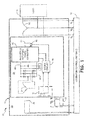
FIG. 1 is a circuit diagram of an electric power generation and distribution system according to an embodiment of the present invention. -
FIG. 2 is a circuit diagram of an electric power generation and distribution system according to an embodiment of the present invention. -
FIG. 3 is a circuit diagram of a high voltage direct current (HVDC) electric power generation and distribution system according to an embodiment of the present invention. -
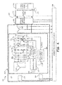
FIG. 4 is a circuit diagram of a high voltage direct current (HVDC) electric power generation and distribution system according to an embodiment of the present invention. -
FIG. 1 is a circuit diagram of electric power generation anddistribution system 10 according to an embodiment of the present invention.System 10 includesgenerator 12, generator control unit (GCU) 14, andload 16.Generator 12 is divided intostationary portion 24 and rotatingportion 26.Stationary portion 24 includes exciter field winding 28, stationary communication module 29 (which in this embodiment includes coil 30), andmain armature windings 32. Rotatingportion 26 includesexciter armature windings 34, rotating communication module 35 (which in this embodiment includes coil 36),rectifier 38, direct current (DC) link capacitor CdcR,DC link bus 40, main fieldrotating power converter 42,main field winding 44, andcurrent sensor 46. - Generator control unit (GCU) 14 is responsible for regulation and protection of
generator 12. Regulation refers to maintaining the output voltage ofgenerator 12 provided by main armature winding 32 at a desired level. Protection refers, at least in part, to preventing faults such as overvoltage faults fromdamaging generator 12 or attachedloads 16. As discussed in more detail below, the output voltage is regulated by either regulating the current supplied to exciter field winding 28 (as is normally done in wound field synchronous machines) or regulating the current supplied tomain field winding 44 located on the rotatingportion 26 ofgenerator 12. Regulation of the output voltage via control the current supplied to main field winding 44 requires communication of commands/instructions/feedback across the air gap separatingstationary portion 24 from rotatingportion 26. Likewise, overvoltage protection is provided by communicating commands/instructions across the air gap separatingstationary portion 24 from rotatingportion 26. As discussed in more detail below, based on the received instructions/commands, main field rotatingpower converter 42 selectively applies voltage to main field winding 44. - In the embodiment shown in
FIG. 1 ,GCU 14 is connected to monitor the output voltage provided by main armature winding 32, provide excitation (e.g., current) to exciterfield winding 28, and communicate commands, instructions, and/or feedback to rotatingportion 26 ofgenerator 12 viastationary communication module 29. Excitation supplied to exciter field winding 28 induces an AC voltage in exciter armature winding 34 located on rotatingportion 26. The AC voltage generated on exciter armature winding 34 is rectified byrectifier 38 and DC link capacitor CdcR to a DC voltage that is supplied to main fieldrotating power converter 42 viaDC link bus 40. In the embodiment shown inFIG. 1 ,rectifier 38 is a passive rectifier comprised of a plurality of bridge-connected diodes. In other embodiments,rectifier 38 may be an active rectifier in which the diodes are replaced with a plurality of solid-state switches selectively controlled to provide a DC output to main fieldrotating power converter 42. Main fieldrotating power converter 42 selectively applies voltage fromDC link 40 to main field winding 44, allowing current to build up in main field winding 44 when main fieldrotating power converter 42 is On and dissipating current in main field winding 44 when main fieldrotating power converter 42 is Off. Current throughmain field winding 44 induces an AC voltage in main armature winding 32 that is monitored byGCU 14 and supplied to load 16. - In one embodiment, main field rotating
power converter 42 includes one or more switches that are turned On and Off to selectively control the supply of current to main field winding 44. The state of main field rotatingpower converter 42 is modified based on feedback/commands received fromGCU 14 via stationary androtating communication modudles stationary portion 24 and rotatingportion 26. In the embodiment shown inFIG. 1 , stationary and rotatingcommunication modules coils 30 and 36, which form a rotating transformer. Control instructions generated byGCU 14 are communicated to primary winding 30 and communicated across the airgap tosecondary coil 36 via magnetic induction. In the embodiment shown inFIG. 1 , communications are unidirectional, fromGCU 14 to rotatingportion 26. However, in other embodiments the communication betweenGCU 14 and rotatingportion 26 may be bi-directional, with instructions, feedback and commands communicated both ways. - In one embodiment, main field rotating
power converter 42 provides overvoltage protection togenerator 12. The typical response to an overvoltage condition is to remove the excitation from exciter field winding 24. However, the lag between the time in which excitation is removed from exciter field winding 28 and when excitation is removed from main field winding 44 (which induces the output voltage on main armature winding 32) may result in voltages that are damaging togenerator 12 and/orload 16. In embodiments in which main fieldrotating power converter 42 is utilized to provide protection, but not regulation of generator output voltage,GCU 14 selectively controls the supply of current provided to exciter field winding 28 to regulate the output voltage provided by main armature winding 32. The voltage induced in response to the exciter field winding current is provided without regulation by main field rotatingpower converter 42 to main field winding 44, allowing current to build up in main field winding 44. In response to an overvoltage condition detected byGCU 14, a command is communicated to rotatingportion 26 to cause main field rotatingpower converter 42 to remove excitation from main field winding 44. In the embodiment shown inFIG. 1 , commands provided byGCU 14 are communicated across the air gap betweenstationary portion 24 and rotatingportion 26 by inductively coupledtransformer windings 30 and 36. Primary winding 30 is located onstationary portion 24 andsecondary winding 36 is located on rotatingportion 26. In the embodiment shown inFIG. 1 , the command received onsecondary winding 36 is communicated directly todriver circuit 46, which in response commands main fieldrotating power converter 42 to turn Off. In other embodiments, the command may require demodulation before being provided to main field rotatingpower converter 42. In response to the received command, main field rotating power converter turns Off, thereby preventing the supply of voltage from rotatingrectifier 38 to main field winding 44. In addition, when Off, main field rotatingpower converter 42 may be configured to quickly dissipate current from main field winding 44, thereby quickly reducing the voltage induced on main armature winding 32. - In another embodiment, utilized either independently or in conjunction with the overvoltage protection provided by the architecture, main field rotating
power converter 42 can be used to selectively regulate the current supplied to main field winding 44 in order to regulate the output voltage of main armature winding 32. In this embodiment, rather than regulate the output voltage ofgenerator 12 via control of the current supplied to exciter field winding 28, the output voltage ofgenerator 12 is regulated via control the current supplied to main field winding 44. In this embodiment, the current supplied to exciter field winding 28 may not be regulated, but rather kept constant byGCU 14. Feedback regarding the output voltage ofgenerator 12 is communicated byGCU 14 to rotatingportion 26 via stationary androtating communication modules FIG. 1 to communicate instructions across the airgap betweenstationary portion 24 and rotatingportion 26, other means of communicating data over the air gap may be employed. Further, as described in more detail below, the type of feedback supplied byGCU 14 to main field rotatingpower converter 42 may vary depending on the embodiment. For example, in oneembodiment GCU 14 monitors the output voltage ofgenerator 12 and provides commands to main field rotatingpower converter 42 regarding the magnitude of the current to be applied to main field winding 44. These commands may include a duty cycle that determines the On/Off time of main field rotatingpower converter 42 and thus the magnitude of the current to be supplied to main field winding 44. In other embodiments,GCU 14 monitors the output voltage and communicates the monitored output voltage to main field rotatingpower converter 42, which based on the received feedback provides regulation of the current supplied to main field winding 44. That is, regulation based on the monitored output voltage is determined on rotatingportion 26, rather than onstationary portion 24 byGCU 14 and then communicated to rotatingportion 26. - In addition, communication between
GCU 14 and rotatingportion 26 may be bi-directional, with rotating communication module providing feedback toGCU 14 regarding the monitored current through main field winding 44. In particular, in embodiments in which regulation is performed by GCU 14 (rather than on rotating portion 26), then the current through main field winding 44 is compared to a reference value to determine whether current should be increased or decreased. In embodiments in which regulation is performed on rotatingportion 26, then monitored current through main field winding 44 may not be communicated toGCU 14, but rather utilized locally on rotatingportion 26 to regulate the current through main field winding 44. - In this way, main field rotating
power converter 42, in combination with means for communicating across the airgap betweenstationary portion 24 and rotatingportion 26, allows the output voltage ofgenerator 12 to be regulated via regulation of the main field winding current. -
FIG. 2 is a circuit diagram of electric power generation anddistribution system 50 according to an embodiment of the present invention. The architecture ofgenerator 52 utilizes main field rotatingpower converter 92 for protection purposes only (i.e., does not provide for regulation of main field winding current).System 50 includesgenerator 52, generator control unit (GCU) 56,current sensor 58, and AC load andmanagement system 60.Generator 12 includesstationary portion 64 and rotating portion 66.Stationary portion 64 includes exciter field winding 68, primary winding 70, and main armature winding 74. Rotating portion 66 includes exciter armature winding 76, first secondary winding 78, second secondary winding 80, hi-side gate driver 82 and low-side gate driver 84, rotating rectifier 90, main field rotatingpower converter 92 and main field winding 94. Main field rotatingpower converter 92 includes hi-side switch T1r, low-side switch T2r, and diodes D1r and D2r. - In the embodiment shown in
FIG. 2 , when switches T1r and T2r are both turned On then the positive DC voltage provided by rotating rectifier is applied to main field winding 94 and allows current to build up in main field winding 94. In particular, a conductive current path is created from the DC output of rotating rectifier 90 through switch T1r to main field winding 94, and then through switch T2r. When switches T1r and T2r are both Off, then current from rotatingrectifier 92 is prevented from being supplied to main field winding 94. In this embodiment, current through main field winding 94 is controlled by regulating the current supplied to exciter field winding 68. Thus,GCU 56 regulates the current through exciter field winding 68 based on the monitored output ofgenerator 52. In response to an overvoltage condition detected byGCU 56, the GCU generates a command to turn Off switches T1r and T2r. The command generated byGCU 56 is communicated via primary winding 70 to first and secondsecondary windings gate drive circuits - In this way, regulation of the generator output is still controlled via regulation of the current through exciter field winding 68, but the transient response to detected overvoltage conditions is improved by communicated a command to rotating portion 66 to turn Off switches T1r and T2r associated with main field rotating
power converter 92. By turning Off switches T1r and T2r, current through main field winding 94 is quickly dissipated through diodes D1r and D2r such that the AC voltage induced on main armature winding 74 is quickly decreased. -
FIG. 3 is a circuit diagram of a high voltage direct current (HVDC) electric power generation anddistribution system 100 according to an embodiment of the present invention. The embodiment shown inFIG. 3 allows for both protection and regulation of the main field winding current. -
System 100 includesgenerator 102,exciter converter circuit 104, generator control unit (GCU) 106,current sensor 108,main output contactors 110,rectifier 112, andconstant power load 114.Generator 102 includesstationary portion 116 androtating portion 118.Stationary portion 116 includes exciter field winding 120, first primary winding 122, second primary winding 124, and main armature winding 126. Rotatingportion 118 includes exciter armature winding 128, first secondary winding 130, second secondary winding 132,demodulator 134,driver 136, hi-side/low-side gate driver 138,modulator 140, rotating rectifier 142, main field rotatingpower converter 144 and main field winding 146. Main field rotatingpower converter 144 includes hi-side switch T1r, low-side switch T2r, and diodes D1r and D2r.Exciter converter circuit 104 includescurrent sensor 148,exciter power converter 150,voltage sensor 152,battery 154, DC link capacitor Cdc, andexciter rectifier 156. - In the embodiment shown in
FIG. 3 , additional circuitry has been added to allow the current through main field winding 146 to be regulated, as opposed to simply turned On or Off for protection purposes. As discussed with respect to the embodiment shown inFIG. 2 , switches T1r and T2r, as well as diodes D1r and D2r are configured as an asymmetric H-bridge circuit in which voltage supplied by rotating rectifier 142 is provided to main field winding 146 when both switches T1r and T2r are On and prevented from being supplied to main field winding 146 when both switches T1r and T2r are Off. In the embodiment shown inFIG. 3 , the current through main field winding 146 is regulated by maintaining switch T2r in an On state and pulse width modulating switch T1r. - To enable regulation of current through main field winding 146, bi-directional communication is required between
rotation portion 118 and GCU 106. In particular, the current through main field winding 146 is monitored viacurrent sensor 148. The monitored current I_field is provided tomodulator 140, which together withdriver circuit 136 converts the monitored current to a format (e.g., pulse stream) that can be communicated across the airgap viasecond transformer windings rectifier 112 to load 114. In response to the monitored DC voltage, GCU 106 generates a reference current value I_ref that represents the desired current through main field winding 146. GCU 106 compares the reference current value I_ref to the monitored current I_field to generate command instructions for the switches T1r and T2r. The command instructions are communicated to rotatingportion 118 via first primary winding 122 and first secondary winding 132.Demodulator 134 decodes the command instructions and provides the instructions to hi-side/low-wide gate driver 138 to selectively turn switches T1r and T2r On and Off as commanded. During normal operation low-side switch T2r remains in the On state, and only hi-side switch T1r is modulated On and Off. However, if an overvoltage condition is detected then low-side switch T2r may be commanded to the Off position (along with hi-side switch T1r) to prevent voltage from being supplied to main field winding 146 and to quickly drain current from main field winding 146. - In this way, regulation of the generator output voltage is handled, not by regulation of the current through exciter field winding 120, but rather through regulation of the current through main field winding. Because regulation of the output voltage is provided via control of the current through main field winding 146, the current through exciter field winding 120 may be regulated or unregulated.
- In the embodiment shown in
FIG. 3 ,exciter converter 104 regulates the exciter field current to provide a constant rotating power supply voltage (i.e., the voltage provided by rotating rectifier 142) that is independent of generator speed. For example, as the speed of the generator increases, the current supplied to exciter field winding 120 is decreased to provide a constant voltage to main field rotatingpower converter 144. Providing a constant voltage to main field rotatingpower converter 144 simplifies the control algorithm employed by GCU 106 in regulating the current through main field winding 146. -
Exciter converter 104 utilizes the AC output voltage ofgenerator 102 as an input to source the excitation provided to exciter field winding 120. The AC voltage is rectified byexciter rectifier 156, with the DC output ofexciter power supply 156 being supplied toexciter converter 150.Voltage sensor 152 monitors the DC voltage supplied toexciter converter 150, andbattery 154 supplies voltage to the DC bus if the DC voltage supplied byexciter rectifier 156 is insufficient. For example, whenfirst starting generator 102, no output voltage will be generated atmain armature windings 126 until excitation is provided to exciter field winding 120. In the embodiment shown inFIG. 3 ,battery 154 provides DC voltage during start-up ofgenerator 102. - GCU 106 monitors the current supplied to exciter field winding 120 via
current sensor 148 and utilizesexciter converter 150 to regulate the current supplied to exciter field winding 120 to maintain a constant current. In the embodiment shown inFIG. 3 , exciter converter includes first and second switches T1e, T2e, and diodes D1e, D2e, connected in an asymmetric H-bridge configuration in which GCU 106 modulates switch T1e to regulate the current supplied to exciter field winding 120. As discussed above, in an asymmetric H-bridge converter, switch T2e remains On while switch T1e is modulated On and Off to regulate the current supplied to exciter field winding 120. Although an asymmetric H-bridge converter is shown, in other embodiments, other well-know converter circuits may be used to regulate the current supplied to exciter field winding 120. In this way,exciter converter circuit 104 regulates the exciter field current to provide a constant DC power supply provided by exciter armature winding 128 that is independent of generator speed. - In another embodiment, the current supplied to exciter field winding 120 is unregulated. In this embodiment, AC voltage supplied by main armature winding 126 is rectified by
exciter rectifier 156 and supplied directly to exciter field winding 120. In this embodiment, the resulting voltage provided by exciter armature winding 128 is not regulated and becomes a function of generator speed. However, the current through main field winding 146 may still be regulated via main field rotatingpower converter 144. -
FIG. 4 is a circuit diagram of a high voltage direct current (HVDC) electric power generation anddistribution system 162 according to an embodiment of the present invention.System 162 includesgenerator 162, generator control unit (GCU) 164,current sensor 166,main output contactor 168,rectifier 170,load 172 andvoltage sensor 173.Generator 162 includesstationary portion 174 androtating portion 176.Stationary portion 174 includes exciter field winding 178, primary winding 180, and main armature winding 182. Rotatingportion 176 includes exciter armature winding 184,demodulator 186, PWMcurrent regulator 188, hi-side/low-side gate driver 190, rotatingrectifier 192, DC link capacitor CdcR, main field rotatingpower converter 194, main field winding 196, andcurrent sensor 198. Main field rotating power converter includes hi-side switch T1r, low-side switch T2r and diodes D1r, D2r connected in an asymmetric H-bridge configuration. - In contrast with the embodiment shown in
FIG. 3 , in which the monitored current I_field through the main field winding was communicated to the GCU for regulation calculations, in the embodiment shown inFIG. 4 , rotatingportion 176 includes PWMcurrent regulator 188 to provide regulation of the main field winding current. A benefit of this approach, is the monitored current does not have to be communicated across the air gap to the GCU, with command instructions subsequently provided by the GCU in response to the monitored current. - In the embodiment shown in
FIG. 4 ,GCU 164 monitors the output voltage of main armature winding 182. Based on the monitored output voltage,GCU 164 generates a a main field winding reference current (labeled I_ref) that is communicated to rotatingportion 176 viatransformer windings Demodulator 187 demodulates the signal received at secondary winding 186 and provided the received reference current I_ref to PWMcurrent regulator 188, which compares the reference current I_ref to monitored current I_Field. Based on the comparison, PWMcurrent regulator 188 generates command signals provided to hi-side/low-side gate driver 190 to selectively turn hi-side switch T1r and low-side switch T2r On and Off. During normal operation, switch T2r is normally maintained in the On state, while switch T1r is pulse width modulated to generate the desire current through main field winding 196. In addition, during overvoltage conditions, both switches T1r and T2r may be turned Off to provide protection togenerator 162 by quickly dissipating the current from main field winding 196. - In the embodiment shown in
FIG. 4 ,GCU 164 supplies a desired current to exciter field winding 178. As discussed above, the current supplied to exciter field winding 178 may be regulated such that the voltage generated in exciter armature winding 184 is independent of generator speed or may be unregulated. - The following are non-exclusive descriptions of possible embodiments of the present invention.
- A generator comprises a stationary portion and a rotating portion. The stationary portion includes a main armature winding. The rotating portion includes a main field winding and a main field rotating power converter that selectively controls current supplied to the main field winding.
- The generator of the preceding paragraph can optionally include, additionally and/or alternatively, any one or more of the following features, configurations and/or additional components.
- In any of the foregoing embodiments, the main field rotating power converter may further include a high-side switch connected between a positive DC voltage of a DC bus link and a high side of the main field winding, a low-side switch connected between a negative DC voltage of the DC bus link and a low side of the main field winding, a first diode connected between the high side of the main field winding and the negative DC voltage, and a second diode connected between the low side of the main field winding and the positive DC voltage.
- In any of the foregoing embodiments, the high-side switch and the low-side switch may be turned On to allow the DC voltage provided by the DC bus link to be supplied to the main field winding and turned Off to dissipate current in the main field winding via the first and second diode.
- In any of the foregoing embodiments, the low-side switch may be turned On and the high-side switch may be modulated On and Off to regulate the current through the main field winding.
- In any of the foregoing embodiments, wherein the generator may further include a stationary communication module located on the stationary portion and a rotating communication module located on the rotating portion that is coupled to receive input from the stationary communication module. The rotating communication module communicates instructions received from the stationary communication module to the main field rotating power converter to selectively apply the DC voltage provided by the DC link bus to the main field winding.
- In any of the foregoing embodiments, the rotating communication module communicates may receive instructions from the stationary communication module to the main field rotating power converter to regulate the current through the main field winding.
- In any of the foregoing embodiments, the stationary communication module may include a first primary winding. The rotating communication module may include a first secondary winding inductively coupled to the first primary winding and a second secondary winding inductively coupled to the first primary winding.
- In any of the foregoing embodiments, the generator may further include a high side switch connected between a positive DC voltage of a DC link bus and a high side of the main field winding, and a low-side switch connected between a negative DC voltage of a DC link bus and a low side of the main field winding, a first diode connected between the high side of the main field winding and the negative DC voltage, and a second diode connected between the low side of the main field winding and the positive DC voltage. The generator may further include a high-side gate drive circuit connected to drive the high-side switch On and Off based on input received from the first secondary winding and a low-side gate drive circuit connected to drive the low-side switch On and off based on input received from the second secondary winding, wherein an instruction communicated to the first primary winding is communicated to both the high-side gate drive circuit via the first secondary winding and the low-side gate drive circuit via the second secondary winding.
- In any of the foregoing embodiments, the stationary communication module may include a first primary winding and a second primary winding. The rotating communication module may include a first secondary winding and a second secondary winding, wherein the first primary winding is inductively coupled with the first secondary winding to communicate instructions from the stationary portion to the rotating portion and the second primary winding is inductively coupled with the second secondary winding to communicate feedback from the rotating portion to the stationary portion.
- In any of the foregoing embodiments, the generator may further include a demodulator coupled to demodulate instructions communicated via the first primary winding and the first secondary winding, a gate drive circuit that controls the state of the main field rotating power converter based on the demodulated instructions, a current sensor that monitors current through the main field winding, a modulator that modulates the sensed current, and a driver circuit coupled to the second secondary winding to communicate the modulated sensed current as feedback from the rotating portion to the stationary portion via second secondary winding and the second primary winding.
- In any of the foregoing embodiments, the main field rotating power converter may include a high-side switch connected between a positive DC voltage of a DC link bus and a high side of the main field winding, a low-side switch connected between a negative DC voltage of the DC link bus and a low side of the main field winding, a first diode connected between the high side of the main field winding and the negative DC voltage, and a second diode connected between the low side of the main field winding and the positive DC voltage, wherein current through the main field winding is regulated by maintaining the low-side switch in an On state and pulse width modulating the high-side switch based on demodulated instructions received via the first primary winding and the first secondary winding.
- In any of the foregoing embodiments, the stationary communication module may include a primary winding and the rotating communication module includes a secondary winding inductively coupled to the primary winding.
- In any of the foregoing embodiments, the generator may further include a demodulator coupled to the secondary winding to demodulate instructions received from the primary winding, including a reference current representing a desired current to be provided through the main field winding, and a pulse-width modulator (PWM) current regulator connected to monitor current through the main field winding and compare the monitored current to the reference current to calculated PMW control signals provided to the main field rotating power converter to selectively apply the DC voltage to the main field winding.
- A generator system may include a generator, a stationary communication module, a rotating communication module, a generator control unit, and a main field rotating power converter. The generator may include a stationary portion and a rotating portion, wherein the generator includes a main field winding on the rotating portion and an main armature winding on the stationary portion. The rotating communication module is located on the rotating portion of the generator and may be configured to receive communications from the stationary communication module. The generator control unit is connected to monitor the output voltage generated by the main armature winding of the generator and to provide instructions via the stationary communication module to the rotating portion of the generator. The main field rotating power converter located on the rotating portion of the generator that in response to instructions received from the GCU selectively controls excitation provided to the main field winding.
- The generator system of the preceding paragraph can optionally include, additionally and/or alternatively, any one or more of the following features, configurations and/or additional components.
- In any of the foregoing embodiments, in response to an overvoltage condition detected by the generator control unit, the generator control unit may provide an instruction to the main field rotating power converter to remove excitation from the main field winding.
- In any of the foregoing embodiments, in response to monitored output voltage of the generator, the generator control unit may provide instructions to the rotating portion of the generator to selectively turn main field rotating power converter On and Off to regulate current through the main field winding.
- In any of the foregoing embodiments, in response to monitored output voltage of the generator, the generator control unit provides a current reference value to the rotating portion of the generator, wherein the rotating portion includes a pulse-width modulation current regulator that selectively turns the main field rotating power converter On and Off to regulate the current through the main field winding.
- In any of the foregoing embodiments, the main field rotating power converter may further include a high-side switch connected between a positive DC voltage of a DC bus link and a high side of the main field winding, a low-side switch connected between a negative DC voltage of the DC bus link and a low side of the main field winding, a first diode connected between the high side of the main field winding and the negative DC voltage, and a second diode connected between the low side of the main field winding and the positive DC voltage.
- In any of the foregoing embodiments, the high-side switch and the low-side switch may be turned On to allow the DC voltage provided by the DC bus link to be supplied to the main field winding and turned Off to dissipate current in the main field winding via the first and second diode.
- In any of the foregoing embodiments, the low-side switch may be turned On and the high-side switch may be modulated On and Off to regulate the current through the main field winding.
- While the invention has been described with reference to an exemplary embodiment(s), it will be understood by those skilled in the art that various changes may be made and equivalents may be substituted for elements thereof without departing from the scope of the invention. In addition, many modifications may be made to adapt a particular situation or material to the teachings of the invention without departing from the essential scope thereof. Therefore, it is intended that the invention not be limited to the particular embodiment(s) disclosed, but that the invention will include all embodiments falling within the scope of the appended claims.
Claims (15)
- A generator (12, 52) comprising:a stationary portion (24, 64) that includes a main armature winding (32, 74); anda rotating portion (26) that includes a main field winding (44, 94) and a main field rotating power converter (42, 92) that selectively controls current supplied to the main field winding (44).
- The generator of claim 1, wherein the main field rotating power converter (42, 92) includes:a high-side switch (T1r) connected between a positive DC voltage of a DC bus link and a high side of the main field winding (44, 94);a low-side switch (T2r) connected between a negative DC voltage of the DC bus link and a low side of the main field winding;a first diode connected between the high side of the main field winding and the negative DC voltage; anda second diode connected between the low side of the main field winding and the positive DC voltage.
- The generator of claim 2, wherein the high-side switch (T1r) and the low-side switch (T2r) are turned On to allow the DC voltage provided by the DC bus link to be supplied to the main field winding (44, 94) and turned Off to dissipate current in the main field winding via the first and second diode (D1r, D2r).
- The generator of claim 2, wherein the low-side switch (T2r) is turned On and the high-side switch (T1r) is modulated On and Off to regulate the current through the main field winding (44, 94).
- The generator of claim 1, further comprising:a stationary communication module (29) located on the stationary portion (24, 64); anda rotating communication module (35) located on the rotating portion (26, 66) that is coupled to receive input from the stationary communication module (29), wherein the rotating communication module communicates instructions received from the stationary communication module (29) to the main field rotating power converter to selectively apply the DC voltage provided by the DC link bus to the main field winding.
- The generator of claim 5, wherein the rotating communication module communicates instructions received from the stationary communication module to the main field rotating power converter to regulate the current through the main field winding.
- The generator of claim 5, wherein the stationary communication module (29) includes a first primary winding and the rotating communication module includes a first secondary winding inductively coupled to the first primary winding and a second secondary winding inductively coupled to the first primary winding.
- The generator of claim 7, further including:a high-side switch (T1r) connected between a positive DC voltage of a DC link bus and a high side of the main field winding (44, 94);a low-side switch (T2r) connected between a negative DC voltage of a DC link bus and a low side of the main field winding (44, 94);a first diode connected between the high side of the main field winding and the negative DC voltage; anda second diode connected between the low side of the main field winding and the positive DC voltage;a high-side gate drive circuit connected to drive the high-side switch On and Off based on input received from the first secondary winding (78); anda low-side gate drive circuit connected to drive the low-side switch On and off based on input received from the second secondary winding (88), wherein an instruction communicated to the first primary winding is communicated to both the high-side gate drive circuit via the first secondary winding (78) and the low-side gate drive circuit via the second secondary winding (88).
- The generator of claim 5, wherein the stationary communication module includes a first primary winding (122) and a second primary winding (124) and the rotating communication module includes a first secondary winding (130) and a second secondary winding (132), wherein the first primary winding (122) is inductively coupled with the first secondary winding (130) to communicate instructions from the stationary portion to the rotating portion (118) and the second primary winding (124) is inductively coupled with the second secondary winding (132) to communicate feedback from the rotating portion (118) to the stationary portion.
- The generator of claim 9, further including:a demodulator (134) coupled to demodulate instructions communicated via the first primary winding (122) and the first secondary winding (130);a gate drive circuit that controls the state of the main field rotating power converter based on the demodulated instructions;a current sensor (148) that monitors current through the main field winding;a modulator (140) that modulates the sensed current; anda driver circuit (136) coupled to the second secondary winding (132) to communicate the modulated sensed current as feedback from the rotating portion (118) to the stationary portion via second secondary winding (132) and the second primary winding (124).
- The generator of claim 10, wherein the main field rotating power converter includes:a high-side switch connected between a positive DC voltage of a DC link bus and a high side of the main field winding;a low-side switch connected between a negative DC voltage of the DC link bus and a low side of the main field winding;a first diode connected between the high side of the main field winding and the negative DC voltage; anda second diode connected between the low side of the main field winding and the positive DC voltage, wherein current through the main field winding is regulated by maintaining the low-side switch in an On state and pulse width modulating the high-side switch based on demodulated instructions received via the first primary winding and the first secondary winding.
- The generator of claim 5, wherein the stationary communication module includes a primary winding and the rotating communication module includes a secondary winding inductively coupled to the primary winding.
- The generator of claim 12, further including:a demodulator (134) coupled to the secondary winding to demodulate instructions received from the primary winding, including a reference current representing a desired current to be provided through the main field winding; anda pulse-width modulator (PWM) current regulator connected to monitor current through the main field winding and compare the monitored current to the reference current to calculated PMW control signals provided to the main field rotating power converter to selectively apply the DC voltage to the main field winding.
- A generator system comprising:the generator of any preceding claim;a stationary communication module (29) located on the stationary portion (24, 64) of the generator;a rotating communication module (35) located on the rotating portion (26, 66) of the generator and configured to receive communications from the stationary communication module (29);a generator control unit (164) connected to monitor the output voltage generated by the main armature winding (32, 44) of the generator and to provide instructions via the stationary communication module to the rotating portion of the generator; andwherein said main field rotating power converter is located on the rotating portion of the generator and, in response to instructions received from the GCU, selectively controls excitation provided to the main field winding.
- The generator system of claim 14, wherein in response to an overvoltage condition detected by the generator control unit (164), the generator control unit provides an instruction to the main field rotating power converter to remove excitation from the main field winding, and/or wherein in response to monitored output voltage of the generator, the generator control unit (164) provides instructions to the rotating portion of the generator to selectively turn main field rotating power converter On and Off to regulate current through the main field winding, and/or wherein in response to monitored output voltage of the generator, the generator control unit (164) provides a current reference value to the rotating portion of the generator, wherein the rotating portion includes a pulse-width modulation current regulator that selectively turns the main field rotating power converter On and Off to regulate the current through the main field winding.
Applications Claiming Priority (1)
| Application Number | Priority Date | Filing Date | Title |
|---|---|---|---|
| US13/833,809 US9054610B2 (en) | 2013-03-15 | 2013-03-15 | Generator architecture with main field rotating power converter |
Publications (2)
| Publication Number | Publication Date |
|---|---|
| EP2779423A2 true EP2779423A2 (en) | 2014-09-17 |
| EP2779423A3 EP2779423A3 (en) | 2017-12-13 |
Family
ID=50272369
Family Applications (1)
| Application Number | Title | Priority Date | Filing Date |
|---|---|---|---|
| EP14158794.9A Pending EP2779423A3 (en) | 2013-03-15 | 2014-03-11 | Generator architecture with main field rotating power converter |
Country Status (2)
| Country | Link |
|---|---|
| US (1) | US9054610B2 (en) |
| EP (1) | EP2779423A3 (en) |
Families Citing this family (16)
| Publication number | Priority date | Publication date | Assignee | Title |
|---|---|---|---|---|
| US8928166B2 (en) * | 2011-08-31 | 2015-01-06 | Hamilton Sundstrand Corporation | Mixed mode power generation architecture |
| US9252695B2 (en) * | 2014-03-12 | 2016-02-02 | General Electric Company | Brushless permanent magnet generator plus auxiliary voltage source constant potential exciter |
| US9771164B2 (en) | 2014-10-27 | 2017-09-26 | Hamilton Sundstrand Corporation | Electric system architecture included in a more-electric engine (MEE) system |
| US10256758B2 (en) | 2014-11-26 | 2019-04-09 | Kohler Co. | Printed circuit board based exciter |
| US9998047B2 (en) | 2015-01-16 | 2018-06-12 | Hamilton Sundstrand Corporation | Synchronous machine with rechargeable power storage devices |
| US20160268942A1 (en) * | 2015-03-12 | 2016-09-15 | Hamilton Sundstrand Corporation | Control of Hybrid Permanent Magnet Machine With Rotating Power Converter and Energy Source |
| US10075106B2 (en) | 2015-04-10 | 2018-09-11 | Hamilton Sundstrand Corporation | DC synchronous machine |
| US10033252B2 (en) | 2015-04-14 | 2018-07-24 | Hamilton Sundstrand Corporation | Sensorless control of a DC synchronous machine |
| US9660563B2 (en) | 2015-06-19 | 2017-05-23 | Hamilton Sundstrand Corporation | High voltage direct current system with improved generator excitation |
| US9548691B1 (en) * | 2015-06-24 | 2017-01-17 | Hamilton Sundstrand Corporation | Variable speed constant frequency power generator including permanent magnet exciter |
| US9941827B2 (en) * | 2016-06-08 | 2018-04-10 | Hamilton Sundstrand Corporation | High voltage DC power generating system including selectively removable neutral node |
| DE102017201687A1 (en) * | 2017-02-02 | 2018-08-02 | Siemens Aktiengesellschaft | A controllable voltage generating device and method for operating a controllable voltage generating device |
| US11509202B2 (en) | 2017-12-28 | 2022-11-22 | Abb Schweiz Ag | Variable flux permanent magnet motor |
| US10581357B2 (en) | 2018-05-11 | 2020-03-03 | Abb Schweiz Ag | Rotating direct current power supply for synchronous machines |
| US11671038B2 (en) | 2019-08-09 | 2023-06-06 | Hamilton Sundstrand Corporation | Control of a wound field synchronous generator for transient load response |
| CA3147839A1 (en) * | 2019-08-16 | 2021-02-25 | Wolfgang BAECK | Power electronic converter |
Citations (2)
| Publication number | Priority date | Publication date | Assignee | Title |
|---|---|---|---|---|
| US6362588B1 (en) * | 2000-02-09 | 2002-03-26 | Reliance Electric Technologies, Llc | Excitation system for rotating synchronous machines |
| US20090289870A1 (en) * | 2007-03-19 | 2009-11-26 | Ahmadreza Rofougaran | Method and System for Using a Transformer for FM Transmit and FM Receive Functionality |
Family Cites Families (20)
| Publication number | Priority date | Publication date | Assignee | Title |
|---|---|---|---|---|
| US3768002A (en) * | 1971-10-01 | 1973-10-23 | Gen Electric | Generator excitation system with rotating electromagnetic energy connector and internal winding power source |
| DE2247718A1 (en) * | 1972-09-28 | 1974-04-11 | Siemens Ag | DEVICE FOR INDUCTIVE TRANSFER OF DATA BETWEEN A FIXED AND A ROTATING PART OF ELECTRIC MACHINERY |
| DE2945599C2 (en) * | 1979-11-12 | 1985-07-11 | Siemens AG, 1000 Berlin und 8000 München | Device for sway dampening of regulated electrical machines |
| DE3206338A1 (en) * | 1982-02-22 | 1983-09-01 | Kraftwerk Union AG, 4330 Mülheim | ARRANGEMENT FOR THE CONTACT AND CONTACTLESS TRANSMISSION OF MEASURING AND CONTROL SIGNALS |
| US4625160A (en) * | 1984-12-17 | 1986-11-25 | Sundstrand Corporation | Variable speed constant frequency generating system |
| US4723106A (en) * | 1986-08-29 | 1988-02-02 | General Electric Company | Brushless generator exciter using hybrid rectifier |
| US5029263A (en) | 1989-10-19 | 1991-07-02 | Sundstrand Corporation | Electric start control of a VSCF system |
| US5153498A (en) | 1989-11-07 | 1992-10-06 | Sundstrand Corporation | Generic control unit |
| US5055765A (en) | 1990-09-04 | 1991-10-08 | Sundstrand Corporation | Voltage regulator for direct current aircraft power bus |
| US5233286A (en) | 1991-07-29 | 1993-08-03 | Sundstrand Corporation | Hybrid 270 volt DC system |
| US5488286A (en) | 1993-05-12 | 1996-01-30 | Sundstrand Corporation | Method and apparatus for starting a synchronous machine |
| US6420842B1 (en) | 2000-01-11 | 2002-07-16 | American Superconductor Corporation | Exciter and electronic regulator for rotating machinery |
| US7106030B2 (en) * | 2004-01-14 | 2006-09-12 | Vanner, Inc. | Field excitation for an alternator |
| US7196498B2 (en) | 2004-09-08 | 2007-03-27 | Honeywell International Inc. | Method and apparatus for generator control |
| US7064524B2 (en) | 2004-09-08 | 2006-06-20 | Honeywell International Inc. | Method and apparatus for generator control |
| US8730702B2 (en) * | 2009-03-03 | 2014-05-20 | Renewable Power Conversion, Inc. | Very high efficiency three phase power converter |
| GB2469128A (en) * | 2009-04-04 | 2010-10-06 | Dyson Technology Ltd | Generating control signals for an electric machine from a position sensor |
| US8199545B2 (en) * | 2009-05-05 | 2012-06-12 | Hamilton Sundstrand Corporation | Power-conversion control system including sliding mode controller and cycloconverter |
| US8810189B2 (en) * | 2011-02-25 | 2014-08-19 | Deere & Company | Machine systems including pre-power diagnostics |
| FR2976747B1 (en) * | 2011-06-15 | 2014-02-14 | Leroy Somer Moteurs | ALTERNATOR WITH VOLTAGE REGULATION |
-
2013
- 2013-03-15 US US13/833,809 patent/US9054610B2/en active Active
-
2014
- 2014-03-11 EP EP14158794.9A patent/EP2779423A3/en active Pending
Patent Citations (2)
| Publication number | Priority date | Publication date | Assignee | Title |
|---|---|---|---|---|
| US6362588B1 (en) * | 2000-02-09 | 2002-03-26 | Reliance Electric Technologies, Llc | Excitation system for rotating synchronous machines |
| US20090289870A1 (en) * | 2007-03-19 | 2009-11-26 | Ahmadreza Rofougaran | Method and System for Using a Transformer for FM Transmit and FM Receive Functionality |
Also Published As
| Publication number | Publication date |
|---|---|
| US9054610B2 (en) | 2015-06-09 |
| US20140266078A1 (en) | 2014-09-18 |
| EP2779423A3 (en) | 2017-12-13 |
Similar Documents
| Publication | Publication Date | Title |
|---|---|---|
| US9054610B2 (en) | Generator architecture with main field rotating power converter | |
| US9325229B2 (en) | Generator architecture with PMG exciter and main field rotating power converter | |
| US8975876B2 (en) | Method of controlling rotating main field converter | |
| EP2779424B1 (en) | EPGS architecture with multi-channel synchronous generator and common unregulated PMG exciter | |
| EP2779425B1 (en) | Epgs architecture with multi-channel synchronous generator and common field regulated exciter | |
| EP2109932B1 (en) | Method of and apparatus for controlling excitation | |
| US8970183B2 (en) | Overvoltage limiter in an aircraft electrical power generation system | |
| US9318937B2 (en) | Flux controlled PM electric machine rotor | |
| US6909262B2 (en) | Control system for regulating exciter power for a brushless synchronous generator | |
| US20100308582A1 (en) | Starting/generating system with multi-functional circuit breaker | |
| EP2779428B1 (en) | Variable speed constant frequency system with generator and rotating power converter | |
| US20140176087A1 (en) | Alternator with voltage regulation | |
| US9088230B2 (en) | Dual generator system | |
| US20130234678A1 (en) | Alternator ripple voltage reduction using output feedback to an independent field coil | |
| CN106471730B (en) | It is powered with exciting current to synchronous motor | |
| EP3255779B1 (en) | Reconfigurable multi-permanent magnet generator based power generating system | |
| US10044305B2 (en) | Controlling aircraft VFG over voltage under fault or load-shed | |
| AU2015201770B2 (en) | Self exciting alternator circuit |
Legal Events
| Date | Code | Title | Description |
|---|---|---|---|
| 17P | Request for examination filed |
Effective date: 20140311 |
|
| AK | Designated contracting states |
Kind code of ref document: A2 Designated state(s): AL AT BE BG CH CY CZ DE DK EE ES FI FR GB GR HR HU IE IS IT LI LT LU LV MC MK MT NL NO PL PT RO RS SE SI SK SM TR |
|
| AX | Request for extension of the european patent |
Extension state: BA ME |
|
| PUAI | Public reference made under article 153(3) epc to a published international application that has entered the european phase |
Free format text: ORIGINAL CODE: 0009012 |
|
| PUAL | Search report despatched |
Free format text: ORIGINAL CODE: 0009013 |
|
| AK | Designated contracting states |
Kind code of ref document: A3 Designated state(s): AL AT BE BG CH CY CZ DE DK EE ES FI FR GB GR HR HU IE IS IT LI LT LU LV MC MK MT NL NO PL PT RO RS SE SI SK SM TR |
|
| AX | Request for extension of the european patent |
Extension state: BA ME |
|
| RIC1 | Information provided on ipc code assigned before grant |
Ipc: H02P 9/10 20060101ALI20171106BHEP Ipc: H02P 9/30 20060101AFI20171106BHEP |
|
| STAA | Information on the status of an ep patent application or granted ep patent |
Free format text: STATUS: REQUEST FOR EXAMINATION WAS MADE |
|
| R17P | Request for examination filed (corrected) |
Effective date: 20180612 |
|
| RBV | Designated contracting states (corrected) |
Designated state(s): AL AT BE BG CH CY CZ DE DK EE ES FI FR GB GR HR HU IE IS IT LI LT LU LV MC MK MT NL NO PL PT RO RS SE SI SK SM TR |
|
| STAA | Information on the status of an ep patent application or granted ep patent |
Free format text: STATUS: EXAMINATION IS IN PROGRESS |
|
| 17Q | First examination report despatched |
Effective date: 20200603 |