EP2779390A2 - Controlled motion system having a magnetic flux bridge joining linear motor sections - Google Patents
Controlled motion system having a magnetic flux bridge joining linear motor sections Download PDFInfo
- Publication number
- EP2779390A2 EP2779390A2 EP14160321.7A EP14160321A EP2779390A2 EP 2779390 A2 EP2779390 A2 EP 2779390A2 EP 14160321 A EP14160321 A EP 14160321A EP 2779390 A2 EP2779390 A2 EP 2779390A2
- Authority
- EP
- European Patent Office
- Prior art keywords
- magnetic flux
- stator
- adjacent
- flux bridge
- gap
- Prior art date
- Legal status (The legal status is an assumption and is not a legal conclusion. Google has not performed a legal analysis and makes no representation as to the accuracy of the status listed.)
- Granted
Links
Images


Classifications
-
- H—ELECTRICITY
- H02—GENERATION; CONVERSION OR DISTRIBUTION OF ELECTRIC POWER
- H02K—DYNAMO-ELECTRIC MACHINES
- H02K41/00—Propulsion systems in which a rigid body is moved along a path due to dynamo-electric interaction between the body and a magnetic field travelling along the path
- H02K41/02—Linear motors; Sectional motors
-
- B—PERFORMING OPERATIONS; TRANSPORTING
- B65—CONVEYING; PACKING; STORING; HANDLING THIN OR FILAMENTARY MATERIAL
- B65G—TRANSPORT OR STORAGE DEVICES, e.g. CONVEYORS FOR LOADING OR TIPPING, SHOP CONVEYOR SYSTEMS OR PNEUMATIC TUBE CONVEYORS
- B65G54/00—Non-mechanical conveyors not otherwise provided for
- B65G54/02—Non-mechanical conveyors not otherwise provided for electrostatic, electric, or magnetic
-
- H—ELECTRICITY
- H02—GENERATION; CONVERSION OR DISTRIBUTION OF ELECTRIC POWER
- H02K—DYNAMO-ELECTRIC MACHINES
- H02K1/00—Details of the magnetic circuit
- H02K1/06—Details of the magnetic circuit characterised by the shape, form or construction
- H02K1/12—Stationary parts of the magnetic circuit
-
- H—ELECTRICITY
- H02—GENERATION; CONVERSION OR DISTRIBUTION OF ELECTRIC POWER
- H02K—DYNAMO-ELECTRIC MACHINES
- H02K1/00—Details of the magnetic circuit
- H02K1/06—Details of the magnetic circuit characterised by the shape, form or construction
- H02K1/12—Stationary parts of the magnetic circuit
- H02K1/14—Stator cores with salient poles
-
- H—ELECTRICITY
- H02—GENERATION; CONVERSION OR DISTRIBUTION OF ELECTRIC POWER
- H02K—DYNAMO-ELECTRIC MACHINES
- H02K41/00—Propulsion systems in which a rigid body is moved along a path due to dynamo-electric interaction between the body and a magnetic field travelling along the path
- H02K41/02—Linear motors; Sectional motors
- H02K41/03—Synchronous motors; Motors moving step by step; Reluctance motors
- H02K41/031—Synchronous motors; Motors moving step by step; Reluctance motors of the permanent magnet type
-
- H—ELECTRICITY
- H02—GENERATION; CONVERSION OR DISTRIBUTION OF ELECTRIC POWER
- H02K—DYNAMO-ELECTRIC MACHINES
- H02K1/00—Details of the magnetic circuit
- H02K1/06—Details of the magnetic circuit characterised by the shape, form or construction
- H02K1/12—Stationary parts of the magnetic circuit
- H02K1/14—Stator cores with salient poles
- H02K1/146—Stator cores with salient poles consisting of a generally annular yoke with salient poles
- H02K1/148—Sectional cores
-
- H—ELECTRICITY
- H02—GENERATION; CONVERSION OR DISTRIBUTION OF ELECTRIC POWER
- H02K—DYNAMO-ELECTRIC MACHINES
- H02K2201/00—Specific aspects not provided for in the other groups of this subclass relating to the magnetic circuits
- H02K2201/15—Sectional machines
Definitions
- the present invention relates generally to controlled motion systems and more specifically, the present invention relates to controlled motion systems having more than one linear motor sections and means of joining the linear motor sections together using a magnetic flux bridge such that the likelihood of interruption or a change in the level of magnetic flux along and between the linear drive sections is reduced.
- Controlled motion systems comprise linear motors, such as linear motors, that employ a moving magnetic field to directly motor a moving element, sometimes known as a carriage, pallet, tray, or mover (referred to here collectively as a "mover").
- linear motors reduce or eliminate the need for gear heads, shafts, keys, sprockets, chains and belts often used with traditional rotary motors.
- This reduction of mechanical complexity provides both reduced cost and increased speed capability by virtue of reducing inertia, compliance, damping, friction and wear normally associated with more conventional motor systems.
- controlled motion systems also provide greater flexibility than rotary motor systems by allowing each individual mover to be independently controlled along its entire path.
- Controlled motion systems typically comprise interconnected track sections, each section has a plurality of individually controlled coils that provide independent control of one or more movers that travel along the track.
- Such systems include a positioning system that often employs a plurality of linear encoders spaced at fixed positions along the track and linear encoder strips mounted on each mover to sense their position.
- Such linear encoders are typically "incremental absolute" position encoders that are coupled to a controller or counter, and that operate by sensing and counting incremental pulses (or that digitize sine/cosine signals to create these pulses) to count up or down after a mover has traveled past a reference point.
- Such incremental encoders can provide an absolute position signal only after performing a homing and commutation alignment procedure for each mover at power up. This requires moving each mover a certain distance along the track to find the zero reference position and the magnetic pole positions.
- tracks are generally assembled by combining individual track sections, wherein each section is adhered or connected to an adjacent section along their contact surfaces, such as by use of an epoxy or other such material, and then covered or encased in stainless steel or similar material.
- a mover travels along the track from section to section through employment of a magnetic field created by the individually controlled coils positioned along each section of the track.
- This disruption or weakening in the magnetic field between adjacent track sections is problematic in that it often leads to lost performance, noise, false readings, or crashes along the track.
- the counting process by the controller or counter is often lost or the pulse counting disrupted.
- Such disruption or weakening requires the movers to be driven back to a reference point of home position to initialize or reset the counting process. This initialization or resetting of the counting process results in significant loss of production time and often lost product.
- the disruption or weakening can result in stoppage of the entire control motion system often resulting in the need to reset or restart other processes.
- a controlled motion system comprising one or more linear motors positioned along a track formed from two or more sections such that the likelihood of interruption or the level of disturbance or weakening in the magnetic field along and between adjacent linear motor sections is reduced or minimized.
- a controlled motion system comprising a track formed from two or more track sections positioned adjacent to one another, at least one linear motor positioned along and coupled to the track sections, one or more movers mounted for moving along the track by way of a controlled magnetic field formed by the at least one linear motor, and at least one magnetic flux bridge between or connecting each adjacent track section, such that any changes, disturbance, or weakening in the control led magnetic field between adjacent track sections is reduced.
- the magnetic flux bridge may comprise magnetically conductive material that allows for a substantially consistent magnetic field to exist between the mover and adjacent track sections over which the mover is moving.
- the magnetic flux bridge may be in the form of shims positioned between adjacent track sections, magnetically conductive adhesives between adjacent sections, magnetically conductive covers encasing the gap between sections, or a combination thereof.
- the magnetic flux bridge may also be in the form of a ferromagnetic plate directly connected to the stator element of each adjacent track section.
- the magnetic flux bridge may comprise a ferromagnetic plate having first portion connected to the stator element of a first track section and a second portion connected to the stator element of a second track section.
- the magnetic flux bridge may operate to minimize the gap between adjacent track sections that may cause a disturbance, change, or weakening in the magnetic field.
- the magnetic flex bridge may have a cross section such that the magnetization of the magnetic flux bridge is not saturated.
- the magnetic flux bridge may be in the form of ferromagnetic plate sections integral with respective stators of adjacent linear motor track sections and effective for reducing any disruption, change, or weakening of the magnetic field between the two adjacent track sections.
- a controlled motion system comprises a track formed from two or more track sections positioned adjacent to one another, at least one linear motor positioned along and coupled to the track sections, one or more movers mounted for moving along the track by way of a controlled magnetic field formed by the at least one linear motor, and at least one magnetic flux bridge between or connecting each adjacent track section, such that any disturbance, change, or weakening in the controlled magnetic field between adjacent track sections is reduced.
- the present disclosure relates to a linear controlled motion system, such as a system having a track formed from one or more track sections, and having at least one mover mounted to the track and effective for receiving articles at one location and transporting the articles to another location.
- the system includes at least one magnetic linear motion motor for providing a magnetic field effective for moving each mover in a controlled motion along the track.
- the controlled motion system includes a magnetic flux bridge for reducing changes in the magnetic flux that would otherwise reduce the efficiency or interfere with the operation of the controlled motion system.
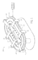
- a schematic representation of a linear controlled motion system 100 comprising a track 102 formed from two or more interconnected track sections 104 having a magnetic motor system 106 comprising activation elements 108, such as a plurality of electromagnet coils 110 coupled to a stator 112 mounted along the track sections 104.
- the electromagnet coils 110 operate to create an electromagnetic field illustrated by magnetic flux lines 114.
- Coupled to the track 102 is at least one mover 116 mounted to permit travel along the track 102.
- Each mover 116 is controlled and may generally move independent of other movers.
- Reaction elements 118 may comprise one or more magnets 120, such as rare-earth permanent magnets.
- each mover 116 cooperates with the activation elements 108 positioned along the track 102 to produce relative movement therebetween when the activation elements 108 are energized and/or de-energized.
- Each mover 116 further includes a control sensor 122 that provides a signal for use by a control system 124 for operating the motor system 106 by energizing and/or de-energizing the activation elements 108 positioned along the track 102 thereby producing controlled movement of each mover 116.
- a control system 124 for operating the motor system 106 by energizing and/or de-energizing the activation elements 108 positioned along the track 102 thereby producing controlled movement of each mover 116.
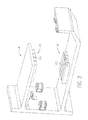
- the controlled motion system 100 includes a positioning system 126 that employs a plurality of linear encoders 128 spaced at fixed positions along the track 102, and that cooperate with the control sensor 122 mounted on each mover 116 to provide signals to the control system 124 for sensing each mover's position along the track 102.
- each control sensor 122 comprises a linear encoder, such as an "incremental absolute" position encoder, that is coupled to the control system 124, and that operates to sense and count incremental pulses (or digitize sine/cosine signals to create these pulses) after a mover 116 has traveled past a reference point (not shown)).
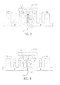
- a portion of the track 102 is shown having two adjacent interconnected track sections 104 and a plurality of electromagnetic coils 110 formed along stators 112 that are mounted along the track sections 104, and that operate to create an electromagnetic field mounted along each track section 104, as illustrated by magnetic flux lines 114 forming a closed loop with the mover 116 and the adjacent track sections 104.
- a gap 132 such as an air gap, exists between the track sections 104.
- Some gap, or a gap at some point between the sections may be useful, however, to facilitate securement of mechanical elements, such as a cover (not shown). However, the gap can create weakening or change in the magnetic flux across the gap 132.
- This disruption or change in the magnetic field between the adjacent track sections 104 is problematic in that it may lead to lost performance, noise, false readings, or unwanted interaction of movers along the track 102. Further, when a mover 116 experiences a change or weakening in the magnetic field during operation of the control motion system 100, the control sensor 122 may sense this change or weakening such that the counting process performed by the control system 124 may be lost or the pulse counting disrupted. Such disruptions may also require the movers 116 to be driven back to a reference point or home position to initialize or reset the counting process. This process results in significant loss of production time and lost production.
- FIG. 6 an exemplary embodiment of the present disclosure is shown in which two adjacent track sections 104 of a linear motion track 102 are connected together and include a a magnetic flux bridge 134 effective for reducing disruption, change, or weakening of the magnetic field between the two adjacent track sections 104 created by gap 132 as shown in FIG. 4 .
- the magnetic flux bridge 134 may be formed in two sections 134a and 134b positioned adjacent to each other and the stators 112a and 112b, respectively, such that that they minimize any disruption, change, or weakening in the magnetic field between two adjacent track sections 104 by providing a flux bridge over or bypassing the gap 132 between the adjacent track sections 104.
- the magnetic flux bridge 134 may be positioned and mounted to stators 112 to permit the magnetic flux 114 to flow such that the magnetic field is substantially consistent along or between the stators 112 of adjacent track sections 104, the magnetic flux bridge 134, and the mover 116.
- the magnetic flux bridge 134 may comprise a ferromagnetic plate or other similar structure directly connected to the stator 112 of each adjacent track section 104, along the underside of the stators. It should be understood that the size, such as thickness T, and the cross sectional area of the magnetic flux bridge 134 is dependent on the particular ferromagnetic material forming the magnetic flux bridge and the strength of the magnetic field, and may be selected to ensure that the magnetic flux 114 is not saturated.
- adjacent surfaces 140 of the magnetic flux bridge 134 may be precisely machined to sufficiently reduce or minimize any gap between the two surfaces, at least in a region through which the flux is to be directed. Such precise machining at such locations can be easily and inexpensively done, and reduces the need to precisely machine the entire adjacent surfaces 142 of the stator sections 112a and 112b.
- each stator section 112a and 112b comprises a generally contiguous base B, with contiguous teeth T that face the mover 16 as it moves along the track sections.
- These stator sections may be made of multiple pieces of laminate material (e.g., magnetic steel) that may be stamped, cut, or otherwise formed, and then joined side-by-side to form the stator sections illustrated.
- the teeth may have different widths and spacing, as illustrated, and depending upon the mechanical, electrical, and magnetic design of the device. At locations corresponding to the location of the gap 132, end teeth ET may be formed as illustrated.
- Such end teeth may allow for some gap, or a portion of a gap, as indicated by the letter G, to remain, such as for attachment of a cover (not shown), or other mechanical, electrical, or magnetic reasons.
- the gap 114 is reduced or substantially eliminated between the contiguous bases B such that flux may be effectively channeled between the adjacent stator sections.
- the particular design for the laminations, and variants of such designs are also considered of interest in accordance with the present disclosure, for improving performance of the device.
- FIG. 7 another embodiment is shown in which two adjacent track sections 104 of a linear motion track 102 are connected together and include a magnetic flux bridge 134 effective for reducing disruption, change, or weakening of the magnetic field between the two adjacent track sections 104.
- the magnetic flux bridge 134 is formed in two sections 134a and 134b and each section is formed integral with respective stators 112a and 112b.
- the two sections 134a and 134b are attached to the respective stators 112a and 112b, such as by bolts, screws, magnetically conductive adhesive, or other suitable method.
- the magnetic flux bridge 134 may comprise a ferromagnetic plate or other similar structure directly connected to the stator 112 of each adjacent track section 104, such as along the underside of the stators.
- the size, such as thickness T, and the cross sectional area of the magnetic flux bridge 134 is dependent on the particular ferromagnetic material forming the magnetic flux bridge and the strength of the magnetic field, and may be selected to ensure that the magnetic flux 114 is not saturated.
- adjacent surfaces 140 of the magnetic flux bridge 134 may be machined to sufficiently reduce or minimize any gap between the two surfaces, and that such machining can be easily and inexpensively done at flux-channeling locations to reduce the need to precisely machine the entire adjacent surfaces 142 of the stator sections 112a and 112b.
- stator sections 112a and 112b may be formed of stamped (or otherwise formed) laminate layers that are stacked to form the stator sections.
- the end teeth ET of such laminates may approach one another while leaving a portion of a gap G, while the contiguous bases B of the stator sections, formed by the base of the laminates, may be extended by an extension E to approach one more closely to reduce or effectively eliminate the gap 114 to more effectively channel flux from one base section B (e.g., of stator section 112a) to the base section B of the adjacent stator section (e.g., 112b).
- the design of such stator sections, and of the laminates of which they may be comprises are considered of interest as potentially significant advances in the art.
- the teeth T comprise teeth of different widths.
- the end teeth ET and the extension E are sized such that when stator sections comprising similar laminates are placed end-to-end, as shown, a base gap 114 between adjacent base extensions is reduced or eliminated, while a gap G between the end teeth is maintained, and a total combined dimension of the gap G between the end teeth and widths of the adjacent end teeth is approximately equal to a width of at least one of the plurality of teeth (e.g., the narrower teeth shown in the figure).
- the magnetic flux bridge 134 comprises one or more ferromagnetic shims 136 positioned within the gap 132 between adjacent track sections 104.
- the magnetic flux bridge 134 comprises a magnetically conductive adhesive 138 positioned within the gap 132 between adjacent track sections 104.
- the magnetic bridge of the subject may comprise a ferromagnetic plate, such as shown in FIGS. 6 and 7 ; one or more ferromagnetic shims, such as shown in FIG. 8 ; magnetically conductive adhesives, such as shown in FIG. 9 ; or a combination thereof.
- the controlled motion system and the magnetic flux bridge of the subject invention operate to provide a substantially greater continuity of the magnetic field operating to move a mover from one track section to another track section.
- the magnetic flux bridge may comprise any one or more forms of magnetically conducting articles and materials effective for operating such that the magnetic field along the carriage and adjacent track sections is substantially maintained without loss or disruption of the magnetic flux.
- the controlled motion system may thus comprise one or more linear motors positioned along a track formed from two or more sections, and a magnetic flux bridge that operates to reduce or minimize the likelihood of interruption or the level of disturbance or weakening in the magnetic field along and between adjacent linear motor sections.
- the use of a magnetic flux bridge may reduce the need to have precise manufacturing tolerances between stators of adjacent track sections.
Landscapes
- Engineering & Computer Science (AREA)
- Power Engineering (AREA)
- Physics & Mathematics (AREA)
- Chemical & Material Sciences (AREA)
- Combustion & Propulsion (AREA)
- Electromagnetism (AREA)
- Linear Motors (AREA)
- Control Of Linear Motors (AREA)
- Control Of Vehicles With Linear Motors And Vehicles That Are Magnetically Levitated (AREA)
Abstract
Description
- This application is a Non-Provisional Patent Application of U.S. Provisional Patent Application No.
61/792,150 - The present invention relates generally to controlled motion systems and more specifically, the present invention relates to controlled motion systems having more than one linear motor sections and means of joining the linear motor sections together using a magnetic flux bridge such that the likelihood of interruption or a change in the level of magnetic flux along and between the linear drive sections is reduced.
- The application of controlled motion systems to a wide variety of processes (e.g. for packaging, transporting objects, assembly automation, and processes involving use of machine tools, etc.) provides the advantage of increasing both the speed and flexibility of the process. Controlled motion systems comprise linear motors, such as linear motors, that employ a moving magnetic field to directly motor a moving element, sometimes known as a carriage, pallet, tray, or mover (referred to here collectively as a "mover"). Such linear motors reduce or eliminate the need for gear heads, shafts, keys, sprockets, chains and belts often used with traditional rotary motors. This reduction of mechanical complexity provides both reduced cost and increased speed capability by virtue of reducing inertia, compliance, damping, friction and wear normally associated with more conventional motor systems. Further, controlled motion systems also provide greater flexibility than rotary motor systems by allowing each individual mover to be independently controlled along its entire path.
- Controlled motion systems typically comprise interconnected track sections, each section has a plurality of individually controlled coils that provide independent control of one or more movers that travel along the track. Such systems include a positioning system that often employs a plurality of linear encoders spaced at fixed positions along the track and linear encoder strips mounted on each mover to sense their position. Such linear encoders are typically "incremental absolute" position encoders that are coupled to a controller or counter, and that operate by sensing and counting incremental pulses (or that digitize sine/cosine signals to create these pulses) to count up or down after a mover has traveled past a reference point. Such incremental encoders, however, can provide an absolute position signal only after performing a homing and commutation alignment procedure for each mover at power up. This requires moving each mover a certain distance along the track to find the zero reference position and the magnetic pole positions.
- The prior art is filled with similar such controlled motion systems utilizing linear motors. However, such systems suffer from a particular deficiency. Specifically, tracks are generally assembled by combining individual track sections, wherein each section is adhered or connected to an adjacent section along their contact surfaces, such as by use of an epoxy or other such material, and then covered or encased in stainless steel or similar material. During actual use of the system, a mover travels along the track from section to section through employment of a magnetic field created by the individually controlled coils positioned along each section of the track. Often, the region between where the mover leaves one section of the track and reaches the next section, there is typically a disturbance or weakening in the magnetic field that results in a relatively large increase in resistance or cogging as compared to the magnetic field in the middle of a section. This disruption or weakening in the magnetic field is a result of an air gap along the contact surfaces of the assembled track sections generally caused by non-precise milling of the adjacent track sections so exposed cores do not magnetically touch, or by the epoxy or other non-magnetic covering (i.e., stainless steel) creating a substantially non-magnetic gap between the individual track sections. This disruption or weakening in the magnetic field between adjacent track sections is problematic in that it often leads to lost performance, noise, false readings, or crashes along the track. Further, when a mover experiences a disruption or weakening in the magnetic field during operation of the motion control system, the counting process by the controller or counter is often lost or the pulse counting disrupted. Such disruption or weakening requires the movers to be driven back to a reference point of home position to initialize or reset the counting process. This initialization or resetting of the counting process results in significant loss of production time and often lost product. Further, depending on the location, the disruption or weakening can result in stoppage of the entire control motion system often resulting in the need to reset or restart other processes.
- Accordingly, what is needed is a controlled motion system comprising one or more linear motors positioned along a track formed from two or more sections such that the likelihood of interruption or the level of disturbance or weakening in the magnetic field along and between adjacent linear motor sections is reduced or minimized.
- Various embodiments presently disclosed include a controlled motion system comprising a track formed from two or more track sections positioned adjacent to one another, at least one linear motor positioned along and coupled to the track sections, one or more movers mounted for moving along the track by way of a controlled magnetic field formed by the at least one linear motor, and at least one magnetic flux bridge between or connecting each adjacent track section, such that any changes, disturbance, or weakening in the control led magnetic field between adjacent track sections is reduced.
- The magnetic flux bridge may comprise magnetically conductive material that allows for a substantially consistent magnetic field to exist between the mover and adjacent track sections over which the mover is moving.
- The magnetic flux bridge may be in the form of shims positioned between adjacent track sections, magnetically conductive adhesives between adjacent sections, magnetically conductive covers encasing the gap between sections, or a combination thereof.
- The magnetic flux bridge may also be in the form of a ferromagnetic plate directly connected to the stator element of each adjacent track section.
- The magnetic flux bridge may comprise a ferromagnetic plate having first portion connected to the stator element of a first track section and a second portion connected to the stator element of a second track section.
- The magnetic flux bridge may operate to minimize the gap between adjacent track sections that may cause a disturbance, change, or weakening in the magnetic field.
- The magnetic flex bridge may have a cross section such that the magnetization of the magnetic flux bridge is not saturated.
- The magnetic flux bridge may be in the form of ferromagnetic plate sections integral with respective stators of adjacent linear motor track sections and effective for reducing any disruption, change, or weakening of the magnetic field between the two adjacent track sections.
- In accordance with certain aspects of the present disclosure, a controlled motion system comprises a track formed from two or more track sections positioned adjacent to one another, at least one linear motor positioned along and coupled to the track sections, one or more movers mounted for moving along the track by way of a controlled magnetic field formed by the at least one linear motor, and at least one magnetic flux bridge between or connecting each adjacent track section, such that any disturbance, change, or weakening in the controlled magnetic field between adjacent track sections is reduced.
- Other advantages, objects, and embodiments of the invention will be apparent from the following description, the accompanying drawings and the appended claims.
- In the present disclosure, reference is made in the following description to the accompanying drawings, in which:
-
FIG. 1 is a schematic representation of a linear controlled motion transport system comprising a linear magnetic motor system, a track formed from at least two track sections and having at least one mover effective for moving along the track; -
FIG. 2 is a schematic illustration of a side view of a track section of the linear motion track ofFIG. 1 showing a plurality of electromagnet coils coupled to a stator and a mover mounted for movement along the track section; -
FIG. 3 is a schematic illustration of a perspective view of a mover having reaction elements mounted thereon which cooperate with the activation elements positioned along the track ofFIG. 1 and further showing a control sensor for providing a signal for use by a control system in moving the mover along the track; -
FIG. 4 is a schematic illustration showing a gap between the two adjacent track sections that can create a disturbance, change, or weakening in the magnetic field along the two adjacent track sections; -
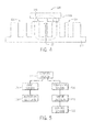
FIG. 5 is an illustration of an exemplary methodology of the control system interacting with the motor system and positioning system of the linear motion control system; -
FIG. 6 is a schematic illustration of a side view of an exemplary embodiment showing two adjacent track sections of a linear motion track connected together and having magnetic flux bridge in the form of a ferromagnetic plate effective for reducing any disruption, change, or weakening of the magnetic field between the two adjacent track sections; -
FIG. 7 is a schematic illustration of a side view of another exemplary embodiment showing two adjacent track sections of a linear motion track connected together and having a magnetic flux bridge in the form of a ferromagnetic plate sections integral with the respective stators and effective for reducing any disruption, change, or weakening of the magnetic field between the two adjacent track sections; -
FIG. 8 is a schematic illustration of a side view of another exemplary embodiment showing two adjacent track sections of a linear motion track connected together and a magnetic flux bridge in the form of a one or more ferromagnetic shims positioned within a gap formed between two adjacent track sections and effective for reducing disruption, change, or weakening of the magnetic field between the two adjacent track sections; and -
FIG. 9 is a schematic illustration of a side view of another exemplary embodiment showing two adjacent track sections of a linear motion track connected together and a magnetic flux bridge in the form of a ferromagnetic adhesive positioned within the gap formed between two adjacent track sections and effective for reducing disruption, change, or weakening of the magnetic field between the two adjacent track sections. - The present disclosure relates to a linear controlled motion system, such as a system having a track formed from one or more track sections, and having at least one mover mounted to the track and effective for receiving articles at one location and transporting the articles to another location. The system includes at least one magnetic linear motion motor for providing a magnetic field effective for moving each mover in a controlled motion along the track. Preferably, the controlled motion system includes a magnetic flux bridge for reducing changes in the magnetic flux that would otherwise reduce the efficiency or interfere with the operation of the controlled motion system. In the present disclosure, specific terminology will be resorted to for the sake of clarity. However, the technology and concepts are not intended to be limited to the specific terms so selected, and it is to be understood that each specific term includes all technical equivalents that operate in a similar manner to accomplish a similar purpose.
- Referring to
FIGS. 1 through 4 , a schematic representation of a linear controlledmotion system 100 is shown comprising atrack 102 formed from two or moreinterconnected track sections 104 having amagnetic motor system 106 comprisingactivation elements 108, such as a plurality of electromagnet coils 110 coupled to astator 112 mounted along thetrack sections 104. The electromagnet coils 110 operate to create an electromagnetic field illustrated bymagnetic flux lines 114. Coupled to thetrack 102 is at least onemover 116 mounted to permit travel along thetrack 102. Eachmover 116 is controlled and may generally move independent of other movers.Reaction elements 118 may comprise one ormore magnets 120, such as rare-earth permanent magnets. Thereaction elements 118 on eachmover 116 cooperate with theactivation elements 108 positioned along thetrack 102 to produce relative movement therebetween when theactivation elements 108 are energized and/or de-energized. Eachmover 116 further includes acontrol sensor 122 that provides a signal for use by acontrol system 124 for operating themotor system 106 by energizing and/or de-energizing theactivation elements 108 positioned along thetrack 102 thereby producing controlled movement of eachmover 116. In an exemplary embodiment, as illustrated inFIG. 5 , the controlledmotion system 100 includes apositioning system 126 that employs a plurality oflinear encoders 128 spaced at fixed positions along thetrack 102, and that cooperate with thecontrol sensor 122 mounted on eachmover 116 to provide signals to thecontrol system 124 for sensing each mover's position along thetrack 102. Preferably, eachcontrol sensor 122 comprises a linear encoder, such as an "incremental absolute" position encoder, that is coupled to thecontrol system 124, and that operates to sense and count incremental pulses (or digitize sine/cosine signals to create these pulses) after amover 116 has traveled past a reference point (not shown)). - Referring to
FIG. 4 , a portion of thetrack 102 is shown having two adjacent interconnectedtrack sections 104 and a plurality of electromagnetic coils 110 formed alongstators 112 that are mounted along thetrack sections 104, and that operate to create an electromagnetic field mounted along eachtrack section 104, as illustrated bymagnetic flux lines 114 forming a closed loop with themover 116 and theadjacent track sections 104. As shown, agap 132, such as an air gap, exists between thetrack sections 104. Some gap, or a gap at some point between the sections may be useful, however, to facilitate securement of mechanical elements, such as a cover (not shown). However, the gap can create weakening or change in the magnetic flux across thegap 132. This disruption or change in the magnetic field between theadjacent track sections 104 is problematic in that it may lead to lost performance, noise, false readings, or unwanted interaction of movers along thetrack 102. Further, when amover 116 experiences a change or weakening in the magnetic field during operation of thecontrol motion system 100, thecontrol sensor 122 may sense this change or weakening such that the counting process performed by thecontrol system 124 may be lost or the pulse counting disrupted. Such disruptions may also require themovers 116 to be driven back to a reference point or home position to initialize or reset the counting process. This process results in significant loss of production time and lost production. - Referring to
FIG. 6 an exemplary embodiment of the present disclosure is shown in which twoadjacent track sections 104 of alinear motion track 102 are connected together and include a amagnetic flux bridge 134 effective for reducing disruption, change, or weakening of the magnetic field between the twoadjacent track sections 104 created bygap 132 as shown inFIG. 4 . Themagnetic flux bridge 134 may be formed in twosections stators adjacent track sections 104 by providing a flux bridge over or bypassing thegap 132 between theadjacent track sections 104. As shown, themagnetic flux bridge 134 may be positioned and mounted tostators 112 to permit themagnetic flux 114 to flow such that the magnetic field is substantially consistent along or between thestators 112 ofadjacent track sections 104, themagnetic flux bridge 134, and themover 116. Themagnetic flux bridge 134 may comprise a ferromagnetic plate or other similar structure directly connected to thestator 112 of eachadjacent track section 104, along the underside of the stators. It should be understood that the size, such as thickness T, and the cross sectional area of themagnetic flux bridge 134 is dependent on the particular ferromagnetic material forming the magnetic flux bridge and the strength of the magnetic field, and may be selected to ensure that themagnetic flux 114 is not saturated. It should be understood that adjacent surfaces 140 of themagnetic flux bridge 134 may be precisely machined to sufficiently reduce or minimize any gap between the two surfaces, at least in a region through which the flux is to be directed. Such precise machining at such locations can be easily and inexpensively done, and reduces the need to precisely machine the entire adjacent surfaces 142 of thestator sections - It may be noted that, in the embodiment illustrated in
FIG. 6 , eachstator section gap 132, end teeth ET may be formed as illustrated. Such end teeth may allow for some gap, or a portion of a gap, as indicated by the letter G, to remain, such as for attachment of a cover (not shown), or other mechanical, electrical, or magnetic reasons. However, in the illustrated embodiment, thegap 114 is reduced or substantially eliminated between the contiguous bases B such that flux may be effectively channeled between the adjacent stator sections. The particular design for the laminations, and variants of such designs are also considered of interest in accordance with the present disclosure, for improving performance of the device. - Referring to
FIG. 7 , another embodiment is shown in which twoadjacent track sections 104 of alinear motion track 102 are connected together and include amagnetic flux bridge 134 effective for reducing disruption, change, or weakening of the magnetic field between the twoadjacent track sections 104. In this embodiment, themagnetic flux bridge 134 is formed in twosections respective stators sections respective stators magnetic flux bridge 134 may comprise a ferromagnetic plate or other similar structure directly connected to thestator 112 of eachadjacent track section 104, such as along the underside of the stators. Here again, it should now be understood that the size, such as thickness T, and the cross sectional area of themagnetic flux bridge 134 is dependent on the particular ferromagnetic material forming the magnetic flux bridge and the strength of the magnetic field, and may be selected to ensure that themagnetic flux 114 is not saturated. It should be understood, here again that adjacent surfaces 140 of themagnetic flux bridge 134 may be machined to sufficiently reduce or minimize any gap between the two surfaces, and that such machining can be easily and inexpensively done at flux-channeling locations to reduce the need to precisely machine the entire adjacent surfaces 142 of thestator sections - Here again, the
stator sections gap 114 to more effectively channel flux from one base section B (e.g., ofstator section 112a) to the base section B of the adjacent stator section (e.g., 112b). Here again, the design of such stator sections, and of the laminates of which they may be comprises, are considered of interest as potentially significant advances in the art. In particular, in the illustrated design, the teeth T comprise teeth of different widths. The end teeth ET and the extension E are sized such that when stator sections comprising similar laminates are placed end-to-end, as shown, abase gap 114 between adjacent base extensions is reduced or eliminated, while a gap G between the end teeth is maintained, and a total combined dimension of the gap G between the end teeth and widths of the adjacent end teeth is approximately equal to a width of at least one of the plurality of teeth (e.g., the narrower teeth shown in the figure). - In another embodiment shown in
FIG. 8 themagnetic flux bridge 134 comprises one or moreferromagnetic shims 136 positioned within thegap 132 betweenadjacent track sections 104. In another embodiment shown inFIG. 9 themagnetic flux bridge 134 comprises a magnetically conductive adhesive 138 positioned within thegap 132 betweenadjacent track sections 104. Here again, it should be apparent that the use offerromagnetic shims 136 reduces the need to precisely machine the adjacent surfaces 142 of thestator sections - It should be understood that the magnetic bridge of the subject may comprise a ferromagnetic plate, such as shown in
FIGS. 6 and 7 ; one or more ferromagnetic shims, such as shown inFIG. 8 ; magnetically conductive adhesives, such as shown inFIG. 9 ; or a combination thereof. - The controlled motion system and the magnetic flux bridge of the subject invention operate to provide a substantially greater continuity of the magnetic field operating to move a mover from one track section to another track section.
- The magnetic flux bridge may comprise any one or more forms of magnetically conducting articles and materials effective for operating such that the magnetic field along the carriage and adjacent track sections is substantially maintained without loss or disruption of the magnetic flux.
- The controlled motion system may thus comprise one or more linear motors positioned along a track formed from two or more sections, and a magnetic flux bridge that operates to reduce or minimize the likelihood of interruption or the level of disturbance or weakening in the magnetic field along and between adjacent linear motor sections. The use of a magnetic flux bridge may reduce the need to have precise manufacturing tolerances between stators of adjacent track sections.
- While this disclosure has set forth specific embodiments presently contemplated, it is evident that many alternatives, modifications and variations will be apparent to those skilled in the art. Accordingly, the embodiments set forth above are intended to be illustrative, not limiting. Various changes may be made without departing from the spirit and scope of the invention. Similarly, for example, it has been found that it may be desireable to provide a gap, such as between end teeth, with a magnetic filler "bridge" disposed within the gap. This may prevent or reduce a tendency to "cog" as the mover is displaced along the track sections while only certain features of the invention have been illustrated and described herein, many modifications and changes will occur to those skilled in the art. It is, therefore, to be understood that the appended claims are intended to cover all such modifications and changes as fall within the true spirit of the invention.
-
- Embodiment 1. A controlled motion system comprising:
- a track formed from two or more track sections positioned adjacent to one another;
- at least one motor positioned along and coupled to at least one of the track sections;
- one or more movers mounted for moving along the track by way of a controlled magnetic field formed by the at least one motor; and
- at least one magnetic flux bridge connecting the adjacent track sections to reduce any changes, disturbance, or weakening in the controlled magnetic field between adjacent track sections.
- Embodiment 2. The controlled motion system of embodiment 1, wherein the magnetic flux bridge comprises magnetically conductive material.
- Embodiment 3. The controlled motion system of embodiment 1, wherein the magnetic flux bridge operates to provide a substantially consistent magnetic field between the mover and adjacent track sections over which the mover is moves.
- Embodiment 4. The controlled motion system of embodiment 1, wherein the magnetic flux bridge comprises shims positioned between said adjacent track sections.
- Embodiment 5. The controlled motion system of embodiment 1, wherein the magnetic flux bridge comprises a conductive adhesive between the adjacent track sections.
- Embodiment 6. The controlled motion system of embodiment 1, wherein the magnetic flux bridge comprises a ferromagnetic plate directly connected to stator elements of the adjacent track sections.
- Embodiment 7. The controlled motion system of embodiment 1, wherein the magnetic flux bridge comprises a ferromagnetic plate having a first portion connected to a stator element of said a first track section and a second portion connected to a stator element of said second track section.
- Embodiment 8. The controlled motion system of embodiment 1, wherein said magnetic flux bridge reduces a portion of the gap between said adjacent track sections while leaving a portion of the gap for mechanical attachment.
- Embodiment 9. The controlled motion system of embodiment 1, wherein the magnetic flux bridge has a cross sectional area selected such that the magnetic flux bridge is not saturated by flux.
- Embodiment 10. A stator for a controlled motion system comprising;
a first stator section having a first contiguous base and a plurality of first teeth including a first end tooth;
a second stator section having a second contiguous base and a plurality of second teeth including a second end tooth, the second stator section being disposed adjacent to the first stator section such that the first and second end teeth are generally adjacent to one another;
a section gap formed between the first and second end teeth; and
a magnetic flux bridge formed between the first and second bases to reduce or eliminate a base gap between the first and second bases. - Embodiment 11. The stator embodiment 10, wherein the magnetic flux bridge comprises magnetically conductive material.
- Embodiment 12. The stator of embodiment 10, wherein the base gap of the magnetic flux bridge is smaller than the section gap.
- Embodiment 13. The stator of embodiment 10, wherein the magnetic flux bridge comprises shims positioned between the adjacent stator sections.
- Embodiment 14. The stator of embodiment 10, wherein the magnetic flux bridge comprises a conductive adhesive between said adjacent stator sections.
- Embodiment 15. The stator of embodiment 10, wherein the magnetic flux bridge comprises a ferromagnetic plate directly connected to stator sections.
- Embodiment 16. The stator of embodiment 10, wherein the magnetic flux bridge comprises a ferromagnetic plate having a first portion disposed adjacent to the first stator section and a second portion disposed adjacent to the second stator section.
- Embodiment 17. The stator of embodiment 10, wherein each stator section comprises a plurality of laminates that, when assembled, provide the section gap and the base gap.
- Embodiment 18. A stator laminate for a controlled motion system comprising;
a substantially contiguous base;
a plurality of teeth including an end tooth extending from the base; and
a base extension to the base extending beyond the end tooth. - Embodiment 19. The laminate of embodiment 18, wherein the end tooth is narrower then any one of the plurality of teeth.
- Embodiment 20. The laminate of embodiment 18, wherein the end tooth and the extension are sized such that when a similar laminate is placed end-to-end with the laminate, a base gap between adjacent base extensions is reduced or eliminated while a gap between the end teeth is maintained, and a total dimension of the gap between the end teeth and widths of the adjacent end teeth is approximately equal to a width of at least one of the plurality of teeth.
Claims (15)
- A controlled motion system comprising:a track formed from two or more track sections positioned adjacent to one another;at least one motor positioned along and coupled to at least one of the track sections;one or more movers mounted for moving along the track by way of a controlled magnetic field formed by the at least one motor; andat least one magnetic flux bridge connecting the adjacent track sections to reduce any changes, disturbance, or weakening in the controlled magnetic field between adjacent track sections.
- The controlled motion system of claim 1, wherein the magnetic flux bridge comprises magnetically conductive material.
- The controlled motion system of claim 1 or 2, wherein the magnetic flux bridge operates to provide a substantially consistent magnetic field between the mover and adjacent track sections over which the mover is moves.
- The controlled motion system of any one of claims 1 to 3, wherein the magnetic flux bridge comprises shims positioned between said adjacent track sections.
- The controlled motion system of any one of claims 1 to 4, wherein the magnetic flux bridge comprises a conductive adhesive between the adjacent track sections.
- The controlled motion system of any one of claims 1 to 5, wherein the magnetic flux bridge comprises a ferromagnetic plate directly connected to stator elements of the adjacent track sections.
- The controlled motion system of any one of claims 1 to 6, wherein the magnetic flux bridge comprises a ferromagnetic plate having a first portion connected to a stator element of said a first track section and a second portion connected to a stator element of said second track section.
- The controlled motion system of any one of claims 1 to 7, wherein said magnetic flux bridge reduces a portion of the gap between said adjacent track sections while leaving a portion of the gap for mechanical attachment.
- The controlled motion system of any one of claims 1 to 8, wherein the magnetic flux bridge has a cross sectional area selected such that the magnetic flux bridge is not saturated by flux.
- A stator for a controlled motion system comprising;
a first stator section having a first contiguous base and a plurality of first teeth including a first end tooth;
a second stator section having a second contiguous base and a plurality of second teeth including a second end tooth, the second stator section being disposed adjacent to the first stator section such that the first and second end teeth are generally adjacent to one another;
a section gap formed between the first and second end teeth; and
a magnetic flux bridge formed between the first and second bases to reduce or eliminate a base gap between the first and second bases. - The stator claim 10, wherein the magnetic flux bridge comprises magnetically conductive material.
- The stator of claim 10, wherein the base gap of the magnetic flux bridge is smaller than the section gap; or
wherein the magnetic flux bridge comprises shims positioned between the adjacent stator sections; or
wherein the magnetic flux bridge comprises a conductive adhesive between said adjacent stator sections; or
wherein the magnetic flux bridge comprises a ferromagnetic plate directly connected to stator sections. - The stator of any one of claims 10 to 12, wherein the magnetic flux bridge comprises a ferromagnetic plate having a first portion disposed adjacent to the first stator section and a second portion disposed adjacent to the second stator section; or
wherein each stator section comprises a plurality of laminates that, when assembled, provide the section gap and the base gap. - A stator laminate for a controlled motion system comprising;
a substantially contiguous base;
a plurality of teeth including an end tooth extending from the base; and
a base extension to the base extending beyond the end tooth. - The laminate of claim 14, wherein the end tooth is narrower then any one of the plurality of teeth; or
wherein the end tooth and the extension are sized such that when a similar laminate is placed end-to-end with the laminate, a base gap between adjacent base extensions is reduced or eliminated while a gap between the end teeth is maintained, and a total dimension of the gap between the end teeth and widths of the adjacent end teeth is approximately equal to a width of at least one of the plurality of teeth.
Applications Claiming Priority (2)
| Application Number | Priority Date | Filing Date | Title |
|---|---|---|---|
| US201361792150P | 2013-03-15 | 2013-03-15 | |
| US14/208,581 US10243441B2 (en) | 2013-03-15 | 2014-03-13 | Controlled motion system having a magnetic flux bridge joining linear motor sections |
Publications (3)
| Publication Number | Publication Date |
|---|---|
| EP2779390A2 true EP2779390A2 (en) | 2014-09-17 |
| EP2779390A3 EP2779390A3 (en) | 2018-03-07 |
| EP2779390B1 EP2779390B1 (en) | 2020-05-13 |
Family
ID=50478666
Family Applications (1)
| Application Number | Title | Priority Date | Filing Date |
|---|---|---|---|
| EP14160321.7A Active EP2779390B1 (en) | 2013-03-15 | 2014-03-17 | Controlled motion system having a magnetic flux bridge joining linear motor sections |
Country Status (2)
| Country | Link |
|---|---|
| US (1) | US10243441B2 (en) |
| EP (1) | EP2779390B1 (en) |
Cited By (10)
| Publication number | Priority date | Publication date | Assignee | Title |
|---|---|---|---|---|
| EP3031755A1 (en) * | 2014-12-04 | 2016-06-15 | Rockwell Automation Technologies, Inc. | Controlled motion system having end teeth to facilitate the formation of a magnetic flux bridge joining linear motor sections |
| EP3031756A1 (en) * | 2014-12-08 | 2016-06-15 | Rockwell Automation Technologies, Inc. | Linear drive transport system and method |
| EP3045399A1 (en) | 2015-01-19 | 2016-07-20 | Cama1 S.p.A. | A packaging machine with a magnetic movers conveyor |
| EP3048711A1 (en) * | 2015-01-23 | 2016-07-27 | Rockwell Automation Technologies, Inc. | Technique for reducing cogging in closed track linear motors |
| AT520108A1 (en) * | 2017-07-03 | 2019-01-15 | B & R Ind Automation Gmbh | Transport device in the form of a long stator linear motor |
| CN109789977A (en) * | 2016-10-05 | 2019-05-21 | 莱特拉姆有限责任公司 | linear motor conveyor system |
| EP3141488B1 (en) * | 2015-09-09 | 2020-04-22 | Tetra Laval Holdings & Finance S.A. | Packaging machine for producing packages from a sheet of packaging material |
| WO2020260566A1 (en) * | 2019-06-27 | 2020-12-30 | Beckhoff Automation Gmbh | Assembly of stator modules for a planar drive system |
| WO2023096694A1 (en) * | 2021-11-23 | 2023-06-01 | Laitram, L.L.C. | Magnetic conveyor system |
| US20240140637A1 (en) * | 2019-08-29 | 2024-05-02 | JLS Automation | Adaptive Container Loading Assembly |
Families Citing this family (18)
| Publication number | Priority date | Publication date | Assignee | Title |
|---|---|---|---|---|
| US11146123B2 (en) * | 2012-02-03 | 2021-10-12 | Green Ray Technologies, Llc | Electric machines with energizable and non-energizerable U-shaped stator segments |
| WO2016141022A1 (en) | 2015-03-02 | 2016-09-09 | Kliklok Corporation | Carton forming or feeding machine with controlled motion |
| US20160268882A1 (en) * | 2015-03-09 | 2016-09-15 | Sumitomo Heavy Industries, Ltd. | Linear motor |
| US10620017B2 (en) | 2017-01-31 | 2020-04-14 | Rockwell Automation Technologies, Inc. | Curvilinear encoder system for position determination |
| US10906748B2 (en) * | 2017-08-09 | 2021-02-02 | Rockwell Automation Technologies, Inc. | Method and apparatus for identifying a mover on a closed track |
| US10483895B2 (en) | 2017-08-25 | 2019-11-19 | Rockwell Automation Technologies, Inc. | Method and apparatus for wireless power transfer to an independent moving cart |
| US10381958B2 (en) | 2017-09-28 | 2019-08-13 | Rockwell Automation Technologies, Inc. | Method and apparatus for commutation of drive coils in a linear drive system with independent movers |
| US11539244B2 (en) | 2017-09-28 | 2022-12-27 | Rockwell Automation Technologies, Inc. | Method and apparatus for data transmission over an inductive link for an independent cart system |
| US10608469B2 (en) * | 2017-09-28 | 2020-03-31 | Rockwell Automation Technologies, Inc. | Method and apparatus for power transfer to an independent moving cart during travel along a track |
| CN113169654B (en) * | 2018-07-24 | 2024-11-15 | 曼斯普林能源股份有限公司 | Linear electromagnetic machine |
| JP2022534713A (en) * | 2019-05-28 | 2022-08-03 | ベーウントエル・インダストリアル・オートメイション・ゲゼルシャフト・ミト・ベシュレンクテル・ハフツング | Conveyor |
| US10985685B1 (en) * | 2019-09-30 | 2021-04-20 | Rockwell Automation Technologies, Inc. | System and method for wireless power transfer in a linear cart system |
| EP3958450A1 (en) * | 2020-08-21 | 2022-02-23 | Schneider Electric Industries SAS | Linear motor system and operating method for same |
| EP3993240A1 (en) | 2020-10-28 | 2022-05-04 | Schneider Electric Industries SAS | Transport system, set for constructing a transport system and method for retrofitting a connector in a transport system |
| JP7802183B2 (en) * | 2022-10-12 | 2026-01-19 | シャンハイ ゴリテック オートメーション カンパニーリミテッド | Stator Module and Transfer System |
| US12121936B1 (en) | 2023-05-31 | 2024-10-22 | General Mills, Inc. | Processing system for handling pieces of product |
| CN119059282A (en) * | 2023-06-02 | 2024-12-03 | B和R工业自动化有限公司 | Electromagnetic transport system |
| CN119976415B (en) * | 2024-12-27 | 2025-11-07 | 北京航空航天大学 | An underground logistics transportation drive system and its driving method |
Family Cites Families (21)
| Publication number | Priority date | Publication date | Assignee | Title |
|---|---|---|---|---|
| CH499185A (en) * | 1967-01-28 | 1970-11-15 | Mini Ind Constructillor | Amplifier converter |
| US3488535A (en) * | 1967-09-22 | 1970-01-06 | Max Baermann | Permanent magnet eddy current brake or clutch |
| JPS5419962B1 (en) | 1969-02-24 | 1979-07-19 | ||
| US4095150A (en) * | 1976-07-12 | 1978-06-13 | Karlheinz Senckel | Two-phase asynchronous motor |
| DE3110339C2 (en) | 1981-03-17 | 1984-09-27 | Thyssen Industrie Ag, 4300 Essen | Method for manufacturing a laminated core for a long-stator linear motor |
| ITMI981537A1 (en) * | 1998-07-06 | 2000-01-06 | Europ Elec Motors Design | STATOR OF SINGLE-PHASE ELECTRIC MOTOR WITH FOUR POLES ARRANGED IN PARALLEL AXES BETWEEN THEM AND DIVIDED INTO OPPOSITE PAIRS WITH RESPECT TO |
| US6148967A (en) * | 1998-07-10 | 2000-11-21 | Alliedsignal Inc. | Non-contacting and torquer brake mechanism |
| TW483216B (en) * | 1998-09-08 | 2002-04-11 | Toshiba Corp | Motor |
| JP3730218B2 (en) * | 2000-08-29 | 2005-12-21 | 三菱電機株式会社 | Stacked stator core and manufacturing method thereof, and rotary motor and manufacturing method thereof |
| JP3894297B2 (en) * | 2001-02-28 | 2007-03-14 | 富士電機機器制御株式会社 | Linear actuator |
| EP1547230B1 (en) * | 2002-06-05 | 2017-03-22 | Jacobs Automation, Inc. | Controlled motion system |
| JP3872055B2 (en) | 2003-06-20 | 2007-01-24 | 三菱電機株式会社 | Linear motor armature |
| DE102004045992A1 (en) * | 2004-09-22 | 2006-04-06 | Siemens Ag | Electric machine |
| DE502005003627D1 (en) | 2004-11-08 | 2008-05-21 | Etel Sa | Linear motor with segment stator |
| US7230355B2 (en) * | 2004-12-21 | 2007-06-12 | Baldor Electric Company | Linear hybrid brushless servo motor |
| DE102006012736A1 (en) * | 2006-03-17 | 2007-09-20 | Siemens Ag | Electric machine |
| DE102006013590A1 (en) * | 2006-03-22 | 2007-09-27 | Siemens Ag | Electric machine, in particular a generator |
| CN102893498A (en) * | 2010-06-02 | 2013-01-23 | 爱信精机株式会社 | Electrical rotary machine |
| US8704422B2 (en) * | 2010-11-18 | 2014-04-22 | Nidec Motor Corporation | Full round stator assembly and electromagnetic machine having high slot fill |
| KR20140018869A (en) * | 2011-01-11 | 2014-02-13 | 큐엠 파워, 인크. | Magnetically isolated phase interior permanent magnet electrical rotating machine |
| US8996161B2 (en) | 2011-05-19 | 2015-03-31 | Rockwell Automation, Inc. | Controlled architecture for transport systems |
-
2014
- 2014-03-13 US US14/208,581 patent/US10243441B2/en active Active
- 2014-03-17 EP EP14160321.7A patent/EP2779390B1/en active Active
Non-Patent Citations (1)
| Title |
|---|
| None |
Cited By (22)
| Publication number | Priority date | Publication date | Assignee | Title |
|---|---|---|---|---|
| US9906110B2 (en) | 2014-12-04 | 2018-02-27 | Rockwell Automation Technologies, Inc. | Controlled motion system having end teeth to facilitate the formation of a magnetic flux bridge joining linear motor sections |
| EP3031755A1 (en) * | 2014-12-04 | 2016-06-15 | Rockwell Automation Technologies, Inc. | Controlled motion system having end teeth to facilitate the formation of a magnetic flux bridge joining linear motor sections |
| US10686356B2 (en) | 2014-12-04 | 2020-06-16 | Rockwell Automation Technologies, Inc. | Controlled motion system having end teeth to facilitate the formation of a magnetic flux bridge joining linear motor sections |
| US10829317B2 (en) | 2014-12-08 | 2020-11-10 | Rockwell Automation Technologies, Inc. | Linear drive transport system and method |
| EP3031756B1 (en) | 2014-12-08 | 2017-09-13 | Rockwell Automation Technologies, Inc. | Linear drive transport system and method |
| US9957119B2 (en) | 2014-12-08 | 2018-05-01 | Rockwell Automation Technologies Inc. | Linear drive transport system and method |
| US9611107B2 (en) | 2014-12-08 | 2017-04-04 | Rockwell Automation Technologies, Inc. | Linear drive transport system and method |
| US10280016B2 (en) | 2014-12-08 | 2019-05-07 | Rockwell Automation Technologies, Inc. | Linear drive transport system and method |
| EP3031756A1 (en) * | 2014-12-08 | 2016-06-15 | Rockwell Automation Technologies, Inc. | Linear drive transport system and method |
| US10773847B2 (en) | 2015-01-19 | 2020-09-15 | CAMA1 S.p.A | Packaging machine with a magnetic movers conveyor |
| EP3045399A1 (en) | 2015-01-19 | 2016-07-20 | Cama1 S.p.A. | A packaging machine with a magnetic movers conveyor |
| EP3048711A1 (en) * | 2015-01-23 | 2016-07-27 | Rockwell Automation Technologies, Inc. | Technique for reducing cogging in closed track linear motors |
| EP3141488B1 (en) * | 2015-09-09 | 2020-04-22 | Tetra Laval Holdings & Finance S.A. | Packaging machine for producing packages from a sheet of packaging material |
| CN109789977A (en) * | 2016-10-05 | 2019-05-21 | 莱特拉姆有限责任公司 | linear motor conveyor system |
| AT520108A1 (en) * | 2017-07-03 | 2019-01-15 | B & R Ind Automation Gmbh | Transport device in the form of a long stator linear motor |
| US10407246B2 (en) | 2017-07-03 | 2019-09-10 | B&R Industrial Automation GmbH | Transport apparatus in the form of a long stator linear motor |
| WO2020260566A1 (en) * | 2019-06-27 | 2020-12-30 | Beckhoff Automation Gmbh | Assembly of stator modules for a planar drive system |
| CN114072995A (en) * | 2019-06-27 | 2022-02-18 | 贝克霍夫自动化有限公司 | Arrangement for a stator module of a flat drive system |
| CN114072995B (en) * | 2019-06-27 | 2024-03-12 | 贝克霍夫自动化有限公司 | Arrangement of stator modules for planar drive systems |
| US20240140637A1 (en) * | 2019-08-29 | 2024-05-02 | JLS Automation | Adaptive Container Loading Assembly |
| WO2023096694A1 (en) * | 2021-11-23 | 2023-06-01 | Laitram, L.L.C. | Magnetic conveyor system |
| US12515896B2 (en) | 2021-11-23 | 2026-01-06 | Laitram, L.L.C. | Magnetic conveyor system |
Also Published As
| Publication number | Publication date |
|---|---|
| US10243441B2 (en) | 2019-03-26 |
| US20140265645A1 (en) | 2014-09-18 |
| EP2779390A3 (en) | 2018-03-07 |
| EP2779390B1 (en) | 2020-05-13 |
Similar Documents
| Publication | Publication Date | Title |
|---|---|---|
| US10243441B2 (en) | Controlled motion system having a magnetic flux bridge joining linear motor sections | |
| US10686356B2 (en) | Controlled motion system having end teeth to facilitate the formation of a magnetic flux bridge joining linear motor sections | |
| CN102348617B (en) | Conveyor belt apparatus and method including magnetically actuated rollers | |
| US6876107B2 (en) | Controlled motion system | |
| EP1160961B1 (en) | Sliding means with built-in moving-magnet linear motor | |
| EP1168585B1 (en) | Sliding means with built-in moving-magnet linear motor | |
| EP3048711B1 (en) | Technique for reducing cogging in closed track linear motors | |
| CN101834511B (en) | Planar transverse magnetic flux switch flux linkage permanent magnet linear motor | |
| EP1193847B1 (en) | Slider unit with built-in moving-coil linear motor | |
| EP2779388B1 (en) | Linear motor and linear conveyance device | |
| EP2288008A2 (en) | Linear and curvilinear motor system | |
| JP5509049B2 (en) | Magnetic encoder, actuator | |
| CN108328249A (en) | A kind of linear transmission system | |
| CN108336885B (en) | Linear motor and mover movement positioning control device thereof | |
| KR101813458B1 (en) | Linear motor | |
| CN113859892A (en) | Linear transmission system | |
| KR20120096906A (en) | Linear motor | |
| US20240283345A1 (en) | Double-sided linear motor | |
| JP2023128398A (en) | Positioning device, drive device, positioning method, positioning program | |
| JP2023128399A (en) | Positioning scale, mover, drive device | |
| JPH0477547B2 (en) | ||
| JPS60102865A (en) | Linear pulse motor | |
| JPS619159A (en) | Linear motor |
Legal Events
| Date | Code | Title | Description |
|---|---|---|---|
| 17P | Request for examination filed |
Effective date: 20140317 |
|
| AK | Designated contracting states |
Kind code of ref document: A2 Designated state(s): AL AT BE BG CH CY CZ DE DK EE ES FI FR GB GR HR HU IE IS IT LI LT LU LV MC MK MT NL NO PL PT RO RS SE SI SK SM TR |
|
| AX | Request for extension of the european patent |
Extension state: BA ME |
|
| PUAI | Public reference made under article 153(3) epc to a published international application that has entered the european phase |
Free format text: ORIGINAL CODE: 0009012 |
|
| PUAL | Search report despatched |
Free format text: ORIGINAL CODE: 0009013 |
|
| AK | Designated contracting states |
Kind code of ref document: A3 Designated state(s): AL AT BE BG CH CY CZ DE DK EE ES FI FR GB GR HR HU IE IS IT LI LT LU LV MC MK MT NL NO PL PT RO RS SE SI SK SM TR |
|
| AX | Request for extension of the european patent |
Extension state: BA ME |
|
| RIC1 | Information provided on ipc code assigned before grant |
Ipc: H02K 1/14 20060101ALI20180129BHEP Ipc: H02K 41/03 20060101AFI20180129BHEP |
|
| STAA | Information on the status of an ep patent application or granted ep patent |
Free format text: STATUS: REQUEST FOR EXAMINATION WAS MADE |
|
| R17P | Request for examination filed (corrected) |
Effective date: 20180814 |
|
| RBV | Designated contracting states (corrected) |
Designated state(s): AL AT BE BG CH CY CZ DE DK EE ES FI FR GB GR HR HU IE IS IT LI LT LU LV MC MK MT NL NO PL PT RO RS SE SI SK SM TR |
|
| REG | Reference to a national code |
Ref country code: DE Ref legal event code: R079 Ref document number: 602014065349 Country of ref document: DE Free format text: PREVIOUS MAIN CLASS: H02K0041030000 Ipc: H02K0001140000 |
|
| GRAP | Despatch of communication of intention to grant a patent |
Free format text: ORIGINAL CODE: EPIDOSNIGR1 |
|
| STAA | Information on the status of an ep patent application or granted ep patent |
Free format text: STATUS: GRANT OF PATENT IS INTENDED |
|
| RIC1 | Information provided on ipc code assigned before grant |
Ipc: B65G 54/02 20060101ALI20191127BHEP Ipc: H02K 41/03 20060101ALI20191127BHEP Ipc: H02K 1/14 20060101AFI20191127BHEP |
|
| INTG | Intention to grant announced |
Effective date: 20191219 |
|
| GRAS | Grant fee paid |
Free format text: ORIGINAL CODE: EPIDOSNIGR3 |
|
| GRAA | (expected) grant |
Free format text: ORIGINAL CODE: 0009210 |
|
| STAA | Information on the status of an ep patent application or granted ep patent |
Free format text: STATUS: THE PATENT HAS BEEN GRANTED |
|
| AK | Designated contracting states |
Kind code of ref document: B1 Designated state(s): AL AT BE BG CH CY CZ DE DK EE ES FI FR GB GR HR HU IE IS IT LI LT LU LV MC MK MT NL NO PL PT RO RS SE SI SK SM TR |
|
| REG | Reference to a national code |
Ref country code: GB Ref legal event code: FG4D |
|
| REG | Reference to a national code |
Ref country code: CH Ref legal event code: EP |
|
| REG | Reference to a national code |
Ref country code: DE Ref legal event code: R096 Ref document number: 602014065349 Country of ref document: DE |
|
| REG | Reference to a national code |
Ref country code: AT Ref legal event code: REF Ref document number: 1271532 Country of ref document: AT Kind code of ref document: T Effective date: 20200615 |
|
| REG | Reference to a national code |
Ref country code: LT Ref legal event code: MG4D |
|
| REG | Reference to a national code |
Ref country code: NL Ref legal event code: MP Effective date: 20200513 |
|
| PG25 | Lapsed in a contracting state [announced via postgrant information from national office to epo] |
Ref country code: NO Free format text: LAPSE BECAUSE OF FAILURE TO SUBMIT A TRANSLATION OF THE DESCRIPTION OR TO PAY THE FEE WITHIN THE PRESCRIBED TIME-LIMIT Effective date: 20200813 Ref country code: GR Free format text: LAPSE BECAUSE OF FAILURE TO SUBMIT A TRANSLATION OF THE DESCRIPTION OR TO PAY THE FEE WITHIN THE PRESCRIBED TIME-LIMIT Effective date: 20200814 Ref country code: IS Free format text: LAPSE BECAUSE OF FAILURE TO SUBMIT A TRANSLATION OF THE DESCRIPTION OR TO PAY THE FEE WITHIN THE PRESCRIBED TIME-LIMIT Effective date: 20200913 Ref country code: LT Free format text: LAPSE BECAUSE OF FAILURE TO SUBMIT A TRANSLATION OF THE DESCRIPTION OR TO PAY THE FEE WITHIN THE PRESCRIBED TIME-LIMIT Effective date: 20200513 Ref country code: SE Free format text: LAPSE BECAUSE OF FAILURE TO SUBMIT A TRANSLATION OF THE DESCRIPTION OR TO PAY THE FEE WITHIN THE PRESCRIBED TIME-LIMIT Effective date: 20200513 Ref country code: PT Free format text: LAPSE BECAUSE OF FAILURE TO SUBMIT A TRANSLATION OF THE DESCRIPTION OR TO PAY THE FEE WITHIN THE PRESCRIBED TIME-LIMIT Effective date: 20200914 Ref country code: FI Free format text: LAPSE BECAUSE OF FAILURE TO SUBMIT A TRANSLATION OF THE DESCRIPTION OR TO PAY THE FEE WITHIN THE PRESCRIBED TIME-LIMIT Effective date: 20200513 |
|
| PG25 | Lapsed in a contracting state [announced via postgrant information from national office to epo] |
Ref country code: HR Free format text: LAPSE BECAUSE OF FAILURE TO SUBMIT A TRANSLATION OF THE DESCRIPTION OR TO PAY THE FEE WITHIN THE PRESCRIBED TIME-LIMIT Effective date: 20200513 Ref country code: LV Free format text: LAPSE BECAUSE OF FAILURE TO SUBMIT A TRANSLATION OF THE DESCRIPTION OR TO PAY THE FEE WITHIN THE PRESCRIBED TIME-LIMIT Effective date: 20200513 Ref country code: BG Free format text: LAPSE BECAUSE OF FAILURE TO SUBMIT A TRANSLATION OF THE DESCRIPTION OR TO PAY THE FEE WITHIN THE PRESCRIBED TIME-LIMIT Effective date: 20200813 Ref country code: RS Free format text: LAPSE BECAUSE OF FAILURE TO SUBMIT A TRANSLATION OF THE DESCRIPTION OR TO PAY THE FEE WITHIN THE PRESCRIBED TIME-LIMIT Effective date: 20200513 |
|
| REG | Reference to a national code |
Ref country code: AT Ref legal event code: MK05 Ref document number: 1271532 Country of ref document: AT Kind code of ref document: T Effective date: 20200513 |
|
| PG25 | Lapsed in a contracting state [announced via postgrant information from national office to epo] |
Ref country code: AL Free format text: LAPSE BECAUSE OF FAILURE TO SUBMIT A TRANSLATION OF THE DESCRIPTION OR TO PAY THE FEE WITHIN THE PRESCRIBED TIME-LIMIT Effective date: 20200513 Ref country code: NL Free format text: LAPSE BECAUSE OF FAILURE TO SUBMIT A TRANSLATION OF THE DESCRIPTION OR TO PAY THE FEE WITHIN THE PRESCRIBED TIME-LIMIT Effective date: 20200513 |
|
| PG25 | Lapsed in a contracting state [announced via postgrant information from national office to epo] |
Ref country code: AT Free format text: LAPSE BECAUSE OF FAILURE TO SUBMIT A TRANSLATION OF THE DESCRIPTION OR TO PAY THE FEE WITHIN THE PRESCRIBED TIME-LIMIT Effective date: 20200513 Ref country code: ES Free format text: LAPSE BECAUSE OF FAILURE TO SUBMIT A TRANSLATION OF THE DESCRIPTION OR TO PAY THE FEE WITHIN THE PRESCRIBED TIME-LIMIT Effective date: 20200513 Ref country code: IT Free format text: LAPSE BECAUSE OF FAILURE TO SUBMIT A TRANSLATION OF THE DESCRIPTION OR TO PAY THE FEE WITHIN THE PRESCRIBED TIME-LIMIT Effective date: 20200513 Ref country code: CZ Free format text: LAPSE BECAUSE OF FAILURE TO SUBMIT A TRANSLATION OF THE DESCRIPTION OR TO PAY THE FEE WITHIN THE PRESCRIBED TIME-LIMIT Effective date: 20200513 Ref country code: RO Free format text: LAPSE BECAUSE OF FAILURE TO SUBMIT A TRANSLATION OF THE DESCRIPTION OR TO PAY THE FEE WITHIN THE PRESCRIBED TIME-LIMIT Effective date: 20200513 Ref country code: EE Free format text: LAPSE BECAUSE OF FAILURE TO SUBMIT A TRANSLATION OF THE DESCRIPTION OR TO PAY THE FEE WITHIN THE PRESCRIBED TIME-LIMIT Effective date: 20200513 Ref country code: SM Free format text: LAPSE BECAUSE OF FAILURE TO SUBMIT A TRANSLATION OF THE DESCRIPTION OR TO PAY THE FEE WITHIN THE PRESCRIBED TIME-LIMIT Effective date: 20200513 Ref country code: DK Free format text: LAPSE BECAUSE OF FAILURE TO SUBMIT A TRANSLATION OF THE DESCRIPTION OR TO PAY THE FEE WITHIN THE PRESCRIBED TIME-LIMIT Effective date: 20200513 |
|
| REG | Reference to a national code |
Ref country code: DE Ref legal event code: R097 Ref document number: 602014065349 Country of ref document: DE |
|
| PG25 | Lapsed in a contracting state [announced via postgrant information from national office to epo] |
Ref country code: SK Free format text: LAPSE BECAUSE OF FAILURE TO SUBMIT A TRANSLATION OF THE DESCRIPTION OR TO PAY THE FEE WITHIN THE PRESCRIBED TIME-LIMIT Effective date: 20200513 Ref country code: PL Free format text: LAPSE BECAUSE OF FAILURE TO SUBMIT A TRANSLATION OF THE DESCRIPTION OR TO PAY THE FEE WITHIN THE PRESCRIBED TIME-LIMIT Effective date: 20200513 |
|
| PLBE | No opposition filed within time limit |
Free format text: ORIGINAL CODE: 0009261 |
|
| STAA | Information on the status of an ep patent application or granted ep patent |
Free format text: STATUS: NO OPPOSITION FILED WITHIN TIME LIMIT |
|
| 26N | No opposition filed |
Effective date: 20210216 |
|
| PG25 | Lapsed in a contracting state [announced via postgrant information from national office to epo] |
Ref country code: SI Free format text: LAPSE BECAUSE OF FAILURE TO SUBMIT A TRANSLATION OF THE DESCRIPTION OR TO PAY THE FEE WITHIN THE PRESCRIBED TIME-LIMIT Effective date: 20200513 |
|
| PG25 | Lapsed in a contracting state [announced via postgrant information from national office to epo] |
Ref country code: MC Free format text: LAPSE BECAUSE OF FAILURE TO SUBMIT A TRANSLATION OF THE DESCRIPTION OR TO PAY THE FEE WITHIN THE PRESCRIBED TIME-LIMIT Effective date: 20200513 |
|
| REG | Reference to a national code |
Ref country code: CH Ref legal event code: PL |
|
| REG | Reference to a national code |
Ref country code: BE Ref legal event code: MM Effective date: 20210331 |
|
| PG25 | Lapsed in a contracting state [announced via postgrant information from national office to epo] |
Ref country code: CH Free format text: LAPSE BECAUSE OF NON-PAYMENT OF DUE FEES Effective date: 20210331 Ref country code: LU Free format text: LAPSE BECAUSE OF NON-PAYMENT OF DUE FEES Effective date: 20210317 Ref country code: LI Free format text: LAPSE BECAUSE OF NON-PAYMENT OF DUE FEES Effective date: 20210331 Ref country code: IE Free format text: LAPSE BECAUSE OF NON-PAYMENT OF DUE FEES Effective date: 20210317 |
|
| PG25 | Lapsed in a contracting state [announced via postgrant information from national office to epo] |
Ref country code: BE Free format text: LAPSE BECAUSE OF NON-PAYMENT OF DUE FEES Effective date: 20210331 |
|
| PG25 | Lapsed in a contracting state [announced via postgrant information from national office to epo] |
Ref country code: HU Free format text: LAPSE BECAUSE OF FAILURE TO SUBMIT A TRANSLATION OF THE DESCRIPTION OR TO PAY THE FEE WITHIN THE PRESCRIBED TIME-LIMIT; INVALID AB INITIO Effective date: 20140317 |
|
| P01 | Opt-out of the competence of the unified patent court (upc) registered |
Effective date: 20230404 |
|
| PG25 | Lapsed in a contracting state [announced via postgrant information from national office to epo] |
Ref country code: CY Free format text: LAPSE BECAUSE OF FAILURE TO SUBMIT A TRANSLATION OF THE DESCRIPTION OR TO PAY THE FEE WITHIN THE PRESCRIBED TIME-LIMIT Effective date: 20200513 |
|
| PG25 | Lapsed in a contracting state [announced via postgrant information from national office to epo] |
Ref country code: MK Free format text: LAPSE BECAUSE OF FAILURE TO SUBMIT A TRANSLATION OF THE DESCRIPTION OR TO PAY THE FEE WITHIN THE PRESCRIBED TIME-LIMIT Effective date: 20200513 |
|
| PG25 | Lapsed in a contracting state [announced via postgrant information from national office to epo] |
Ref country code: MT Free format text: LAPSE BECAUSE OF FAILURE TO SUBMIT A TRANSLATION OF THE DESCRIPTION OR TO PAY THE FEE WITHIN THE PRESCRIBED TIME-LIMIT Effective date: 20200513 |
|
| PG25 | Lapsed in a contracting state [announced via postgrant information from national office to epo] |
Ref country code: TR Free format text: LAPSE BECAUSE OF FAILURE TO SUBMIT A TRANSLATION OF THE DESCRIPTION OR TO PAY THE FEE WITHIN THE PRESCRIBED TIME-LIMIT Effective date: 20200513 |
|
| PGFP | Annual fee paid to national office [announced via postgrant information from national office to epo] |
Ref country code: GB Payment date: 20260219 Year of fee payment: 13 |
|
| PGFP | Annual fee paid to national office [announced via postgrant information from national office to epo] |
Ref country code: DE Payment date: 20260219 Year of fee payment: 13 |
|
| PGFP | Annual fee paid to national office [announced via postgrant information from national office to epo] |
Ref country code: FR Payment date: 20260219 Year of fee payment: 13 |