EP2779366B1 - Electrical machine having cooling features - Google Patents
Electrical machine having cooling features Download PDFInfo
- Publication number
- EP2779366B1 EP2779366B1 EP14160302.7A EP14160302A EP2779366B1 EP 2779366 B1 EP2779366 B1 EP 2779366B1 EP 14160302 A EP14160302 A EP 14160302A EP 2779366 B1 EP2779366 B1 EP 2779366B1
- Authority
- EP
- European Patent Office
- Prior art keywords
- rotor
- cooling fluid
- cooling
- stator
- electrical machine
- Prior art date
- Legal status (The legal status is an assumption and is not a legal conclusion. Google has not performed a legal analysis and makes no representation as to the accuracy of the status listed.)
- Active
Links
Images

Classifications
-
- H—ELECTRICITY
- H02—GENERATION; CONVERSION OR DISTRIBUTION OF ELECTRIC POWER
- H02K—DYNAMO-ELECTRIC MACHINES
- H02K9/00—Arrangements for cooling or ventilating
- H02K9/02—Arrangements for cooling or ventilating by ambient air flowing through the machine
-
- H—ELECTRICITY
- H02—GENERATION; CONVERSION OR DISTRIBUTION OF ELECTRIC POWER
- H02K—DYNAMO-ELECTRIC MACHINES
- H02K1/00—Details of the magnetic circuit
- H02K1/06—Details of the magnetic circuit characterised by the shape, form or construction
- H02K1/12—Stationary parts of the magnetic circuit
- H02K1/20—Stationary parts of the magnetic circuit with channels or ducts for flow of cooling medium
-
- H—ELECTRICITY
- H02—GENERATION; CONVERSION OR DISTRIBUTION OF ELECTRIC POWER
- H02K—DYNAMO-ELECTRIC MACHINES
- H02K1/00—Details of the magnetic circuit
- H02K1/06—Details of the magnetic circuit characterised by the shape, form or construction
- H02K1/22—Rotating parts of the magnetic circuit
- H02K1/32—Rotating parts of the magnetic circuit with channels or ducts for flow of cooling medium
-
- H—ELECTRICITY
- H02—GENERATION; CONVERSION OR DISTRIBUTION OF ELECTRIC POWER
- H02K—DYNAMO-ELECTRIC MACHINES
- H02K5/00—Casings; Enclosures; Supports
- H02K5/04—Casings or enclosures characterised by the shape, form or construction thereof
- H02K5/20—Casings or enclosures characterised by the shape, form or construction thereof with channels or ducts for flow of cooling medium
- H02K5/207—Casings or enclosures characterised by the shape, form or construction thereof with channels or ducts for flow of cooling medium with openings in the casing specially adapted for ambient air
-
- H—ELECTRICITY
- H02—GENERATION; CONVERSION OR DISTRIBUTION OF ELECTRIC POWER
- H02K—DYNAMO-ELECTRIC MACHINES
- H02K9/00—Arrangements for cooling or ventilating
- H02K9/02—Arrangements for cooling or ventilating by ambient air flowing through the machine
- H02K9/04—Arrangements for cooling or ventilating by ambient air flowing through the machine having means for generating a flow of cooling medium
Definitions
- the present invention relates to electrical machines having cooling features, and in particular, motors, generators and motor/generators having cooling features in the rotor and/or stator.
- JP2011254577A and JP2011254571A disclose electrical machines with a rotor comprising cooling passages, wherein the passages have inlet and discharge ports located at a different radial distance from a rotation axis, creating a centrifugal pumping effect.
- the patent document DE102010013302A1 discloses an electrical machine with a rotor comprising cooling passages, wherein the cooling passages have inlet and discharge ports located at a different circumferential positions.
- JP2008312292A discloses an electrical machine with a stator comprising a cooling passage being designed for creating a turbulence effect.
- an electrical machine comprising: a stator; a rotor in electromagnetic cooperation with the stator; a shaft extending from the rotor; a bearing structured to radially support the shaft and the rotor; and a casing comprising opposite first and second end plates, the first end plate being disposed at a first axial end of the casing and the second end plate being disposed at a second axial end of the casing, the casing being configured to house the stator, the rotor, the shaft and the bearing.
- the shaft is structured to support the rotor and to rotate about an axis of rotation.
- the first end plate is spaced apart from the second end plate in a first axial direction along the axis of rotation.
- the rotor extends along the axis of rotation and includes a first cooling passage extending therethrough and having a first cooling fluid inlet port disposed at a first axial location along the axis of rotation at a first end of the rotor.
- the first cooling passage also has a first cooling fluid discharge port in fluid communication with the first cooling fluid inlet port and disposed radially outward of the first cooling fluid inlet port at a second axial location at a second end of the rotor opposite the first end of the rotor.
- the second axial location is spaced apart from the first axial location in the first axial direction along the axis of rotation.
- the first cooling passage removes heat from the rotor during rotation of the rotor.
- the rotor includes a second cooling passage extending therethrough and having a second cooling fluid inlet port disposed at a third axial location along the axis of rotation at the second end of the rotor.
- the second cooling passage also has a second cooling fluid discharge port in fluid communication with the second cooling fluid inlet port and disposed radially outward of the second cooling fluid inlet port at a fourth axial location at the first end of the rotor.
- the fourth axial location is spaced apart from the third axial location in a second axial direction along the axis of rotation that is opposite the first axial direction.
- the second cooling passage removes heat from the rotor during rotation of the rotor.
- the first and second cooling fluid inlet ports are in communication with respective inlets through the casing with respective first and second cooling fluid supply passages in communication with respective ones of the first and second cooling fluid inlet ports at respective ones of the first and second ends of the rotor.
- the first cooling fluid supply passage is defined between the rotor, the shaft, the second end plate and a first flow guide.
- the first flow guide extends from the first end of the rotor in the second axial direction such that the first cooling fluid inlet port is disposed radially inward of the first flow guide and the second cooling fluid discharge port is disposed radially outward of the first flow guide.
- the second cooling fluid supply passage is defined between the rotor, the shaft, the first end plate and a second flow guide.
- the second flow guide extends from the second end of the rotor in the first axial direction such that the second cooling fluid inlet port is disposed radially inward of the second flow guide and the first cooling fluid discharge port is disposed radially outward of the second flow guide.
- the first and second cooling fluid discharge ports are in communication with respective outlets through the casing with respective first and second cooling fluid exhaust passages in communication with respective ones of the first and second cooling fluid discharge ports at respective ones of the second and first ends of the rotor.
- the first cooling fluid exhaust passage is defined between the rotor, the stator, and the second flow guide.
- the second cooling fluid exhaust passage is defined between the rotor, the stator, and the first flow guide.
- Embodiments of the present invention are directed to cooling features and schemes for cooling electrical machines, such as motors, generators and/or motor generators.
- the electrical machines may be considered high-speed electrical machines.
- the electrical machines may be induction machines or synchronous machines. The rotation of the electrical machine may be exploited for cooling in more than one manner, for example, by mounting a separate fan on the rotor shaft or by mounting or forming a conventional fan onto the rotor.
- cooling is provided via the use of cooling passages in the rotor that effectively form a pump or compressor, e.g. a centrifugal or both an axial and centrifugal pump or compressor that induce flow through the rotor and in some embodiments, the stator as well.
- Some embodiments may generate lower pressures that are more suitable for high speed motors.
- the pressure may be easily adjusted in the manufacturing process of the rotor, e.g., by altering the positions of one or more openings in laminations in a laminated rotor that form the cooling passages in the rotor, or by altering the size of one or more of the openings to effectively function as an orifice to meter the flow of the cooling fluid (e.g., air).
- the cooling fluid e.g., air
- the cooling scheme is symmetrical, wherein the cooling fluid flows in both directions, such as from each end to the opposite end of the rotor and/or stator, which in some embodiments may make the temperature distribution across the machine more homogeneous, and in some embodiments less power (pressure) may be needed for a desired volumetric flow of cooling fluid.
- the stator e.g., the stator core yoke, employs axial cooling channels extending therethrough.
- the cooling passages may be located near the stator slots so that the heat conduction distance is reduced.
- the stator is laminated, and the cooling passages may be formed by forming openings in the laminations, and stacking the stator core in such a manner as to achieve the desired alignment between the openings to thereby form the cooling passages.
- some of the openings in the laminations may be deflected or shifted relative to others, thereby forming turbulators that increase the heat transfer from the wall of the cooling passage to the cooling fluid.
- electrical machine 10 is a motor.
- electrical machine 10 may be a generator or may be a motor/generator.
- electrical machine 10 is an induction motor.
- electrical machine 10 may be a synchronous machine.
- electrical machine 10 may take other forms.
- electrical machine 10 is a high-speed electrical machine. In other embodiments, electrical machine 10 may operate at any speed suitable for the particular application.
- Electrical machine 10 includes a casing 12, a stator 14, a shaft 16, rotor 18 and bearings 20.
- Casing 12 is configured to house stator 14, shaft 16, rotor 18 and bearings 20.
- bearings 20 are mounted in casing 12, e.g., an end plate of casing 12.
- bearings 20 may be mounted and coupled to casing 12 via one or more other structures.
- Bearings 20 are structured to radially support rotor 18, and to react rotor 18 thrust loads.
- Stator 14 includes a plurality of stator windings 22 and a stator core 24.
- Rotor 18 is disposed radially inward of stator core 24.
- stator 14 circumferentially encompasses rotor 18, although in other embodiments, stator 14 may only partially encompass induction rotor 18, e.g., in the form of segments disposed circumferentially around stator 14.
- Rotor 18 is configured for electromagnetic cooperation with stator 14, e.g., to convert electrical power into mechanical power for delivery via shaft 16 in some embodiments and/or to convert mechanical power received from shaft 16 into electrical power for delivery via stator 14 in other embodiments.
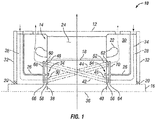
- cooling fluid supply passages 28 are formed between rotor 18, shaft 16, flow guides 26 and end plates 32; and cooling fluid exhaust passages 30 are formed between rotor 18, stator 14, flow guides 26 and casing 12.
- cooling fluid supply passages 28 and cooling fluid exhaust passages 30 may be formed by one or more other components and/or disposed in one or more other locations. Cooling fluid supply passages 28 and cooling fluid exhaust passages 30 are operative to respectively supply and discharge the cooling fluid 34, e.g., air, to and from rotor 18 and electrical machine 10.
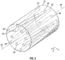
- Rotor 18 extends axially along an axis of rotation 36 about which rotor 18 and shaft 16 rotate, e.g., between an axial position 38 and an axial position 40.
- Rotor 18 includes a plurality of cooling passages 42 extending therethrough.
- the rotor 18 also includes a plurality of passages 44 extending therethrough, as shown in FIG. 1 .
- cooling passages 42 and 44 remove heat from rotor 18 during operation of the electrical machine.
- Cooling passages 42 include cooling fluid inlet ports 46 and cooling fluid discharge ports 48; and cooling passages 44 include cooling fluid inlet ports 50 and cooling fluid discharge ports 52.
- Inlet ports 50 and discharge ports 48 are disposed at axial position 38, and inlet ports 46 and discharge ports 52 are disposed at axial position 40.
- cooling passages do not extend only between the end faces of an electrical machine rotor.
- inlet ports 50 and discharge ports 48, and inlet ports 46 and discharge ports 52 may be disposed at any desired axial position.
- the cooling passages may extend only from one portion to another portion of the electrical machine rotor, not necessarily through the entire axial length of the electrical machine rotor.
- discharge ports 48 and discharge ports 52 are disposed radially outward of inlet ports 46 and inlet ports 50.
- the rotation of rotor 18 generates centrifugal or centripetal forces on the cooling fluid 34 disposed within passages 42 and 44.
- seals 54 which are configured to prevent or reduce the recirculation of fresh and exhausted cooling fluid between the inlet ports 46, 50 and discharge ports 48, 52 on rotor 18.
- seals 54 are labyrinth seals.
- seals 54 may be any contacting or noncontacting seal or flow discourager.
- seals 54 include tips extending from flow guides 26 into a groove in rotor 18.
- seals 54 may be formed with other geometries, and may not be incorporated as part of flow guides 26.
- inlet ports 46, 50 may be disposed at different circumferential positions than discharge ports 48, 52, i.e., wherein during the rotation of rotor 18, discharge ports may lead or may lag the inlet ports, by which rotor 18 effectively functions as an axial pumps or compressor, e.g., in such a manner that a shrouded fan does so.
- This relative positioning of inlet ports 46, 50 and discharge ports 48, 52 may be employed to augment the pressure rise generated across rotor 18 during operation, or to reduce the pressure rise.
- inlet ports 46, 50 and discharge ports 48, 52 may be at the same radial position, but may be located at different circumferential positions such that rotor 18 functions purely as an axial flow machine.
- the inlet ports and discharge ports of the cooling passages may be located so that rotor 18 effectively functions as a centrifugal pump/compressor, both an axial and centrifugal pump/compressor, or may position the inlet ports and discharge ports such that the pressure rise generated by centrifugal/centripetal effects are reduced by those generated by axial flow effects, or may position the inlet ports and discharge ports such that the pressure rise generated by centrifugal/centripetal effects are reduced by those generated by axial flow effects.
- cooling passages 42 and 44 extend linearly between their respective inlet and discharge ports.
- cooling passages 42 and 44 may be geometrically configured, arranged or disposed in any suitable fashion.
- substantially all of one or more of the cooling passages may be horizontal, e.g., maintaining the same radial position along the bulk of the length of rotor 18, but having the inlet ports and discharge ports located at the different radial and/or - in exemplary embodiments not belonging to the invention - axial positions in order to achieve the desired pressure rise across the cooling passages to achieve the desired level of pumping of the cooling fluid.
- cooling passages 42 and 44 have a relatively constant cross-section area or flow area between their respective inlet ports and discharge ports.
- cooling passages 42 and 44 each have a single inlet port and a single discharge port. In other embodiments, cooling passages 42 and 44 may each have more than one inlet port and/or discharge port.
- rotating and/or stationary guide vanes may be employed, e.g., to augment, control, or fine-tune the flow through cooling passages 42 and 44.
- electrical machine 10 includes rotating inlet guide vanes 56 and 58, e.g., extending from rotor 18; rotating discharge guide vanes 60 and 62, e.g. extending from rotor 18; stationery inlet guide vanes 64 and 66, extending from flow guides 26; and stationery discharge guide vanes 68 and 70, e.g. extending from flow guides 26.
- electrical machine 10 may include one or more of rotating inlet guide vanes, stationery inlet guide vanes, rotating discharge guide vanes, and stationary discharge guide vanes.
- guide vanes 56, 58, 60, 62, 64, 66, 68 and 70 extend from respective rotor 18 and flow guides 26 in the illustrated embodiment, in other embodiments, the guide vanes may extend from, or be a part of, or be affixed to any suitable component.
- the rotating and stationery inlet guide vanes are configured to direct cooling fluid into inlet ports 46 and 50 and to increase pressure in the cooling fluid in locations adjacent to inlet ports 46 and 50, in order to increase the flow of cooling fluid through passages 42 and 44, e.g., in a manner similar to compressor blades and vanes.
- the rotating and stationery discharge guide vanes are configured to decrease pressure in locations adjacent to discharge ports 48 and 52, in order to increase the amount of flow of cooling fluid through passages 42 and 44.
- the discharge guide vanes may reduce discharge turbulence by shielding the discharge port from recirculation vortices and the like, and entrain the cooling fluid into the slipstream adjacent to the rotor, e.g., functioning in a manner similar to that of an ejector, for example, by generating a local rotating low pressure field at the locations of the discharge ports 48 and 52.
- stator 14 or more particularly, the stator core 24 or the stator core yoke of electrical machine 10, includes axial turbulated cooling passages 72 extending therethrough, for removing heat from stator core 24 during the operation of electrical machine 10 via the use of a cooling fluid, e.g., cooling fluid 34.
- a cooling fluid e.g., cooling fluid 34.
- discharge ports 48 and 52 are in fluid communication with cooling fluid inlet ports 74 of turbulated cooling passages 72, and provide a flow of cooling fluid 34 into and through turbulated cooling passages 72.
- rotor 18 may be configured to provide cooling fluid 34 at a sufficient flow rate such that its temperature does not become undesirably high as it passes through rotor 18, hence allowing a desired amount of cooling of stator 14.
- cooling fluid 34 may be cooled by a heat exchanger and/or one or more other heat absorbers prior to entry into turbulated cooling passages 72.
- cooling fluid inlet ports 74 of turbulated cooling passages 72 may be in fluid communication with another source of pressurized cooling fluid in addition to or in place of cooling fluid pressurized by rotor 18.
- stator core 24 is formed of a plurality of laminations 76 that are stacked together, e.g., some of which are illustrated as laminations 76A-76H in FIG. 5 . Openings in the laminations are aligned in a desired fashion to form the cooling passages through the cooling passages through the stator 24.
- turbulated cooling passages 72 In contrast to a smooth cooling passage, e.g., wherein the openings are substantially aligned, and wherein the alignment makes the cooling passage smooth, turbulated cooling passages 72 generate turbulence and increased convective heat transfer by misaligning at least some of the openings in the laminations so that turbulated cooling passages 72 are not smooth.
- at least one or more openings 78 in laminations 76 are offset relative to other openings 78 in laminations 76 so as to form turbulated flowpaths for the cooling fluid (i.e., turbulated cooling passages 72), which increases the convective heat transfer from the walls of the turbulated cooling passages 72 to cooling fluid 34.
- turbulators may be formed by inserting wire spirals or inserting or forming other features into smooth cooling passages in order to provide turbulation, such additional features may increase cost, for example by requiring additional components or requiring additional manufacturing steps and/or assembly steps.
- additional features may increase cost, for example by requiring additional components or requiring additional manufacturing steps and/or assembly steps.
- High-speed electrical machines are smaller in size compared to standard 50/60 Hz machines with the same power level. As a consequence, powerful cooling is desirable in high-speed electrical machines, since the loss density is often much higher than in conventional electrical machines.
- Some high-speed electrical machines e.g., 100-600 kW electrical motors, may be cooled from the outer surface of the housing enclosing the stator core, which requires that the heat be conducted, e.g., from the windings, through the core yoke, the core-housing shrink fit, and the housing.
- this may not be feasible in some high-speed machines, because the heat to be removed is too high relative to the heat path cross-sectional area, which in some cases can lead to overheating. Overheating is of particular concern regarding the stator windings, where increased temperatures have a detrimental effect on the effective life of the electrical machine.
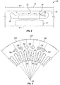
- FIG. 4 depicts 3 different examples of stator cores 24A, 24B and 24C for purposes of describing two methods of forming turbulated passages 72.
- the stator cores are formed as laminations stacked together in such a way as to form a cooling passage.
- Stator core 24A with openings 78A represents a case wherein all openings 78 are in substantial alignment with each other and with stator teeth 80, thus forming a non-turbulated (smooth) cooling passage.
- the openings 78A in each lamination maintain the same alignment relative to stator teeth 80 as the openings 78A in the other laminations and/or the laminations all face in the same direction.
- Stator core 24B with openings 78B represent a methodology of forming turbulated cooling passages 72, wherein the openings 78B in the laminations 76 are all offset from alignment relative to the stator teeth 80, and all openings 78B have the same angular or positional offset from stator teeth 80, in which case turbulated cooling passages 72 are formed by facing at least one of the laminations in a direction opposite to at least another of the laminations.
- every lamination faces in the opposite direction of an adjacent lamination. In other embodiments, only one or some laminations may face oppositely than others.
- the combination of the offset of the openings, and the fact that the laminations face in opposite directions generates the turbulating features that render passages 72 to be turbulated cooling passages.
- Stator core 24C with openings 78C represent a methodology of forming turbulated cooling passages 72, wherein two different lamination geometries are used, e.g., wherein one lamination geometric configuration employs openings having a first angular or positional relationship relative to stator teeth 80, and another lamination geometric configuration employs openings having a second angular or positional relationship relative to stator teeth 80 that is different from the first angular or positional relationship.
- one lamination geometric configuration employs openings having a first angular or positional relationship relative to stator teeth 80
- another lamination geometric configuration employs openings having a second angular or positional relationship relative to stator teeth 80 that is different from the first angular or positional relationship.
- each pair openings 78C in the first lamination geometric configuration are offset from alignment with stator teeth 80 in a direction towards each other, whereas each pair of openings 78C in the second lamination geometric configuration are offset from alignment with stator teeth 80 in a direction away from each other.
- every first opening 78C, circumferentially is rotated about axis of rotation 36 in one direction, e.g., clockwise, and every second opening, circumferentially, is rotated in the opposite direction, e.g., anti-clockwise or counter-clockwise.
- any suitable variation in angular or positional relationship of the openings relative to stator teeth 80 as between the two lamination geometries may be employed.
- more than two different lamination geometric configurations may be employed.
- every adjacent lamination faces in the same direction.
- the combination of two or more lamination geometric configurations having different offsets of the openings relative to stator teeth 80 generates the turbulated cooling passages 72.
Landscapes
- Engineering & Computer Science (AREA)
- Power Engineering (AREA)
- Motor Or Generator Cooling System (AREA)
Description
- The present invention relates to electrical machines having cooling features, and in particular, motors, generators and motor/generators having cooling features in the rotor and/or stator.
- Electrical machines that have cooling features, and cooling features for electrical machines that effectively cool the electrical machines remain an area of interest. Some existing systems have various shortcomings, drawbacks, and disadvantages relative to certain applications. Accordingly, there remains a need for further contributions in this area of technology.
- The patent documents
JP2011254577A JP2011254571A - The patent document
DE102010013302A1 discloses an electrical machine with a rotor comprising cooling passages, wherein the cooling passages have inlet and discharge ports located at a different circumferential positions. - The patent document
JP2008312292A - The invention is defined in the attached independent claim, to which reference should now be made. Optional features are defined in the sub-claims appended thereto.
- According to an aspect there is provided an electrical machine, comprising: a stator; a rotor in electromagnetic cooperation with the stator; a shaft extending from the rotor; a bearing structured to radially support the shaft and the rotor; and a casing comprising opposite first and second end plates, the first end plate being disposed at a first axial end of the casing and the second end plate being disposed at a second axial end of the casing, the casing being configured to house the stator, the rotor, the shaft and the bearing. The shaft is structured to support the rotor and to rotate about an axis of rotation. The first end plate is spaced apart from the second end plate in a first axial direction along the axis of rotation. The rotor extends along the axis of rotation and includes a first cooling passage extending therethrough and having a first cooling fluid inlet port disposed at a first axial location along the axis of rotation at a first end of the rotor. The first cooling passage also has a first cooling fluid discharge port in fluid communication with the first cooling fluid inlet port and disposed radially outward of the first cooling fluid inlet port at a second axial location at a second end of the rotor opposite the first end of the rotor. The second axial location is spaced apart from the first axial location in the first axial direction along the axis of rotation. The first cooling passage removes heat from the rotor during rotation of the rotor. The rotor includes a second cooling passage extending therethrough and having a second cooling fluid inlet port disposed at a third axial location along the axis of rotation at the second end of the rotor. The second cooling passage also has a second cooling fluid discharge port in fluid communication with the second cooling fluid inlet port and disposed radially outward of the second cooling fluid inlet port at a fourth axial location at the first end of the rotor. The fourth axial location is spaced apart from the third axial location in a second axial direction along the axis of rotation that is opposite the first axial direction. The second cooling passage removes heat from the rotor during rotation of the rotor. The first and second cooling fluid inlet ports are in communication with respective inlets through the casing with respective first and second cooling fluid supply passages in communication with respective ones of the first and second cooling fluid inlet ports at respective ones of the first and second ends of the rotor. The first cooling fluid supply passage is defined between the rotor, the shaft, the second end plate and a first flow guide. The first flow guide extends from the first end of the rotor in the second axial direction such that the first cooling fluid inlet port is disposed radially inward of the first flow guide and the second cooling fluid discharge port is disposed radially outward of the first flow guide. The second cooling fluid supply passage is defined between the rotor, the shaft, the first end plate and a second flow guide. The second flow guide extends from the second end of the rotor in the first axial direction such that the second cooling fluid inlet port is disposed radially inward of the second flow guide and the first cooling fluid discharge port is disposed radially outward of the second flow guide. The first and second cooling fluid discharge ports are in communication with respective outlets through the casing with respective first and second cooling fluid exhaust passages in communication with respective ones of the first and second cooling fluid discharge ports at respective ones of the second and first ends of the rotor. The first cooling fluid exhaust passage is defined between the rotor, the stator, and the second flow guide. The second cooling fluid exhaust passage is defined between the rotor, the stator, and the first flow guide.
- The description herein makes reference to the accompanying drawings wherein like reference numerals refer to like parts throughout the several views, and wherein:
-
FIG. 1 schematically illustrates some aspects of a non-limiting example of an electrical machine in accordance with an embodiment of the present invention. -
FIG. 2 schematically illustrates some aspects of a non-limiting example of the electrical machine rotor ofFIG. 1 in accordance with an embodiment of the present invention. -
FIG. 3 schematically illustrates some aspects of a non-limiting example of an electrical machine stator in accordance with an embodiment of the present invention. -
FIG. 4 schematically illustrates some examples of the formation of cooling passages of an electrical machine stator in accordance with embodiments of the present invention. -
FIG. 5 schematically illustrates some aspects of a non-limiting example of a cooling passages of an electrical machine stator in accordance with an embodiment of the present invention. - For purposes of promoting an understanding of the principles of the invention, reference will now be made to the embodiments illustrated in the drawings, and specific language will be used to describe the same. It will nonetheless be understood that no limitation of the scope of the invention is intended by the illustration and description of certain embodiments of the invention. In addition, any alterations and/or modifications of the illustrated and/or described embodiment(s) can be performed within the scope of the present invention as defined in the independent claim. Further, any other applications of the principles of the invention, as illustrated and/or described herein, as would normally occur to one skilled in the art to which the invention pertains, can be contemplated within the scope of the present invention as defined in the independent claim.
- Embodiments of the present invention are directed to cooling features and schemes for cooling electrical machines, such as motors, generators and/or motor generators. In some, but not all embodiments, the electrical machines may be considered high-speed electrical machines. In some, but not all embodiments, the electrical machines may be induction machines or synchronous machines. The rotation of the electrical machine may be exploited for cooling in more than one manner, for example, by mounting a separate fan on the rotor shaft or by mounting or forming a conventional fan onto the rotor. However, such approaches may be cost prohibitive, and in the case of high-speed machines, may not be desirous, e.g., as they might generate more pressure or flow than is desired, or may experience more losses than are preferable, resulting in unnecessarily increased power requirements at the rotor.
- According to the invention, cooling is provided via the use of cooling passages in the rotor that effectively form a pump or compressor, e.g. a centrifugal or both an axial and centrifugal pump or compressor that induce flow through the rotor and in some embodiments, the stator as well. Some embodiments may generate lower pressures that are more suitable for high speed motors. The pressure may be easily adjusted in the manufacturing process of the rotor, e.g., by altering the positions of one or more openings in laminations in a laminated rotor that form the cooling passages in the rotor, or by altering the size of one or more of the openings to effectively function as an orifice to meter the flow of the cooling fluid (e.g., air). According to the invention, the cooling scheme is symmetrical, wherein the cooling fluid flows in both directions, such as from each end to the opposite end of the rotor and/or stator, which in some embodiments may make the temperature distribution across the machine more homogeneous, and in some embodiments less power (pressure) may be needed for a desired volumetric flow of cooling fluid.
- The stator, e.g., the stator core yoke, employs axial cooling channels extending therethrough. The cooling passages may be located near the stator slots so that the heat conduction distance is reduced. In some embodiments, the stator is laminated, and the cooling passages may be formed by forming openings in the laminations, and stacking the stator core in such a manner as to achieve the desired alignment between the openings to thereby form the cooling passages. In some embodiments, some of the openings in the laminations may be deflected or shifted relative to others, thereby forming turbulators that increase the heat transfer from the wall of the cooling passage to the cooling fluid.
- Referring to the drawings, and in particular
FIG. 1 , some aspects of a non-limiting example of anelectrical machine 10 in accordance with an embodiment of the present invention are schematically depicted. In one form,electrical machine 10 is a motor. In other embodiments,electrical machine 10 may be a generator or may be a motor/generator. In one form,electrical machine 10 is an induction motor. In other embodiments,electrical machine 10 may be a synchronous machine. In still other embodiments,electrical machine 10 may take other forms. In one form,electrical machine 10 is a high-speed electrical machine. In other embodiments,electrical machine 10 may operate at any speed suitable for the particular application.Electrical machine 10 includes acasing 12, astator 14, ashaft 16,rotor 18 andbearings 20.Casing 12 is configured to housestator 14,shaft 16,rotor 18 andbearings 20. In one form,bearings 20 are mounted incasing 12, e.g., an end plate ofcasing 12. In other embodiments,bearings 20 may be mounted and coupled to casing 12 via one or more other structures.Bearings 20 are structured to radiallysupport rotor 18, and to reactrotor 18 thrust loads. -
Stator 14 includes a plurality ofstator windings 22 and astator core 24.Rotor 18 is disposed radially inward ofstator core 24. In one form,stator 14 circumferentially encompassesrotor 18, although in other embodiments,stator 14 may only partially encompassinduction rotor 18, e.g., in the form of segments disposed circumferentially aroundstator 14.Rotor 18 is configured for electromagnetic cooperation withstator 14, e.g., to convert electrical power into mechanical power for delivery viashaft 16 in some embodiments and/or to convert mechanical power received fromshaft 16 into electrical power for delivery viastator 14 in other embodiments. - Disposed within casing 12 adjacent to
rotor 18 are flow guides 26, which form coolingfluid supply passages 28 and coolingfluid exhaust passages 30. In the illustrated embodiment, coolingfluid supply passages 28 are formed betweenrotor 18,shaft 16, flow guides 26 andend plates 32; and coolingfluid exhaust passages 30 are formed betweenrotor 18,stator 14, flow guides 26 andcasing 12. In other examples not belonging to the invention, coolingfluid supply passages 28 and coolingfluid exhaust passages 30 may be formed by one or more other components and/or disposed in one or more other locations. Coolingfluid supply passages 28 and coolingfluid exhaust passages 30 are operative to respectively supply and discharge the coolingfluid 34, e.g., air, to and fromrotor 18 andelectrical machine 10. - Referring to
FIG. 2 in conjunction withFIG. 1 , some aspects of a non-limiting example ofelectrical machine 10 androtor 18 in accordance with an embodiment of the present invention are schematically depicted.Rotor 18 extends axially along an axis ofrotation 36 about whichrotor 18 andshaft 16 rotate, e.g., between anaxial position 38 and anaxial position 40.Rotor 18 includes a plurality ofcooling passages 42 extending therethrough. Therotor 18 also includes a plurality ofpassages 44 extending therethrough, as shown inFIG. 1 . In view of the following description, it will become apparent to those skilled in the art that coolingpassages rotor 18 during operation of the electrical machine. Coolingpassages 42 include coolingfluid inlet ports 46 and coolingfluid discharge ports 48; andcooling passages 44 include coolingfluid inlet ports 50 and coolingfluid discharge ports 52.Inlet ports 50 anddischarge ports 48 are disposed ataxial position 38, andinlet ports 46 anddischarge ports 52 are disposed ataxial position 40. In exemplary embodiments not belonging to the present invention cooling passages do not extend only between the end faces of an electrical machine rotor. For example, in those exemplary embodiments,inlet ports 50 anddischarge ports 48, andinlet ports 46 anddischarge ports 52 may be disposed at any desired axial position. In addition, in those exemplary embodiments, the cooling passages may extend only from one portion to another portion of the electrical machine rotor, not necessarily through the entire axial length of the electrical machine rotor. - For each
respective passage discharge ports 48 anddischarge ports 52 are disposed radially outward ofinlet ports 46 andinlet ports 50. As a result of this outer radial displacement ofdischarge ports inlet ports rotor 18 generates centrifugal or centripetal forces on the coolingfluid 34 disposed withinpassages cooling passages inlet ports discharge ports passages inlet ports ports cooling passages rotor 18. -
Electrical machine 10 may includeseals 54, which are configured to prevent or reduce the recirculation of fresh and exhausted cooling fluid between theinlet ports discharge ports rotor 18. In one form, seals 54 are labyrinth seals. In other embodiments, seals 54 may be any contacting or noncontacting seal or flow discourager. In one form, seals 54 include tips extending from flow guides 26 into a groove inrotor 18. In other embodiments, seals 54 may be formed with other geometries, and may not be incorporated as part of flow guides 26. - In some embodiments, for each
respective passage inlet ports discharge ports rotor 18, discharge ports may lead or may lag the inlet ports, by whichrotor 18 effectively functions as an axial pumps or compressor, e.g., in such a manner that a shrouded fan does so. This relative positioning ofinlet ports discharge ports rotor 18 during operation, or to reduce the pressure rise. - In examples that do not embody the invention,
inlet ports discharge ports rotor 18 functions purely as an axial flow machine. Thus in various embodiments, the inlet ports and discharge ports of the cooling passages may be located so thatrotor 18 effectively functions as a centrifugal pump/compressor, both an axial and centrifugal pump/compressor, or may position the inlet ports and discharge ports such that the pressure rise generated by centrifugal/centripetal effects are reduced by those generated by axial flow effects, or may position the inlet ports and discharge ports such that the pressure rise generated by centrifugal/centripetal effects are reduced by those generated by axial flow effects. - In one form, cooling
passages passages rotor 18, but having the inlet ports and discharge ports located at the different radial and/or - in exemplary embodiments not belonging to the invention - axial positions in order to achieve the desired pressure rise across the cooling passages to achieve the desired level of pumping of the cooling fluid. In one form, coolingpassages passages passages - In some embodiments, rotating and/or stationary guide vanes may be employed, e.g., to augment, control, or fine-tune the flow through
cooling passages FIG. 1 ,electrical machine 10 includes rotatinginlet guide vanes rotor 18; rotatingdischarge guide vanes rotor 18; stationeryinlet guide vanes discharge guide vanes electrical machine 10 may include one or more of rotating inlet guide vanes, stationery inlet guide vanes, rotating discharge guide vanes, and stationary discharge guide vanes. Althoughguide vanes respective rotor 18 and flow guides 26 in the illustrated embodiment, in other embodiments, the guide vanes may extend from, or be a part of, or be affixed to any suitable component. - In one form, the rotating and stationery inlet guide vanes are configured to direct cooling fluid into
inlet ports inlet ports passages ports passages discharge ports - Referring now to
FIGS. 3-5 , in some embodiments,stator 14, or more particularly, thestator core 24 or the stator core yoke ofelectrical machine 10, includes axialturbulated cooling passages 72 extending therethrough, for removing heat fromstator core 24 during the operation ofelectrical machine 10 via the use of a cooling fluid, e.g., coolingfluid 34. For example, in some embodiments,discharge ports fluid inlet ports 74 ofturbulated cooling passages 72, and provide a flow of coolingfluid 34 into and throughturbulated cooling passages 72. In such embodiments,rotor 18 may be configured to provide coolingfluid 34 at a sufficient flow rate such that its temperature does not become undesirably high as it passes throughrotor 18, hence allowing a desired amount of cooling ofstator 14. In other embodiments, coolingfluid 34 may be cooled by a heat exchanger and/or one or more other heat absorbers prior to entry intoturbulated cooling passages 72. In other embodiments, coolingfluid inlet ports 74 ofturbulated cooling passages 72 may be in fluid communication with another source of pressurized cooling fluid in addition to or in place of cooling fluid pressurized byrotor 18. - In one form,
turbulated cooling passages 72 are located near the stator slots, e.g., close towindings 22, so that the heat conduction distance is minimized. In one form,stator core 24 is formed of a plurality of laminations 76 that are stacked together, e.g., some of which are illustrated as laminations 76A-76H inFIG. 5 . Openings in the laminations are aligned in a desired fashion to form the cooling passages through the cooling passages through thestator 24. In contrast to a smooth cooling passage, e.g., wherein the openings are substantially aligned, and wherein the alignment makes the cooling passage smooth,turbulated cooling passages 72 generate turbulence and increased convective heat transfer by misaligning at least some of the openings in the laminations so thatturbulated cooling passages 72 are not smooth. For example, in various embodiments of the present invention, at least one ormore openings 78 in laminations 76 are offset relative toother openings 78 in laminations 76 so as to form turbulated flowpaths for the cooling fluid (i.e., turbulated cooling passages 72), which increases the convective heat transfer from the walls of theturbulated cooling passages 72 to coolingfluid 34. - Although it may be possible to form turbulators by inserting wire spirals or inserting or forming other features into smooth cooling passages in order to provide turbulation, such additional features may increase cost, for example by requiring additional components or requiring additional manufacturing steps and/or assembly steps. Thus, it is desirable to have a turbulated passage that does not require additional components, and to have methods of forming the cooling passages that have little or no effect on the time and cost of manufacturing the
stator core 24. - High-speed electrical machines are smaller in size compared to standard 50/60 Hz machines with the same power level. As a consequence, powerful cooling is desirable in high-speed electrical machines, since the loss density is often much higher than in conventional electrical machines. Some high-speed electrical machines, e.g., 100-600 kW electrical motors, may be cooled from the outer surface of the housing enclosing the stator core, which requires that the heat be conducted, e.g., from the windings, through the core yoke, the core-housing shrink fit, and the housing. However, this may not be feasible in some high-speed machines, because the heat to be removed is too high relative to the heat path cross-sectional area, which in some cases can lead to overheating. Overheating is of particular concern regarding the stator windings, where increased temperatures have a detrimental effect on the effective life of the electrical machine.
-
FIG. 4 depicts 3 different examples ofstator cores turbulated passages 72. The stator cores are formed as laminations stacked together in such a way as to form a cooling passage.Stator core 24A withopenings 78A represents a case wherein allopenings 78 are in substantial alignment with each other and withstator teeth 80, thus forming a non-turbulated (smooth) cooling passage. Theopenings 78A in each lamination maintain the same alignment relative to statorteeth 80 as theopenings 78A in the other laminations and/or the laminations all face in the same direction. -
Stator core 24B withopenings 78B represent a methodology of formingturbulated cooling passages 72, wherein theopenings 78B in the laminations 76 are all offset from alignment relative to thestator teeth 80, and allopenings 78B have the same angular or positional offset fromstator teeth 80, in which case turbulated coolingpassages 72 are formed by facing at least one of the laminations in a direction opposite to at least another of the laminations. In the view depicted inFIG. 5 , under the methodology employed with regard toopenings 78B, every lamination faces in the opposite direction of an adjacent lamination. In other embodiments, only one or some laminations may face oppositely than others. The combination of the offset of the openings, and the fact that the laminations face in opposite directions, generates the turbulating features that renderpassages 72 to be turbulated cooling passages. -
Stator core 24C withopenings 78C represent a methodology of formingturbulated cooling passages 72, wherein two different lamination geometries are used, e.g., wherein one lamination geometric configuration employs openings having a first angular or positional relationship relative tostator teeth 80, and another lamination geometric configuration employs openings having a second angular or positional relationship relative tostator teeth 80 that is different from the first angular or positional relationship. In the depiction ofFIG. 4 , eachpair openings 78C in the first lamination geometric configuration are offset from alignment withstator teeth 80 in a direction towards each other, whereas each pair ofopenings 78C in the second lamination geometric configuration are offset from alignment withstator teeth 80 in a direction away from each other. Stated differently, everyfirst opening 78C, circumferentially, is rotated about axis ofrotation 36 in one direction, e.g., clockwise, and every second opening, circumferentially, is rotated in the opposite direction, e.g., anti-clockwise or counter-clockwise. It will be understood that any suitable variation in angular or positional relationship of the openings relative tostator teeth 80 as between the two lamination geometries may be employed. In some embodiments, more than two different lamination geometric configurations may be employed. In the example depicted inFIG. 5 , under the methodology employed with regard toopenings 78C, every adjacent lamination faces in the same direction. The combination of two or more lamination geometric configurations having different offsets of the openings relative tostator teeth 80 generates theturbulated cooling passages 72. - While the invention has been described in connection with what is presently considered to be the most practical and preferred embodiment, it is to be understood that the invention is not to be limited to the disclosed embodiment(s), but on the contrary, is intended to cover various modifications and equivalent arrangements included within the scope of the appended claims. Furthermore, it should be understood that while the use of the word preferable, preferably, or preferred in the description above indicates that feature so described may be more desirable, it nonetheless may not be necessary and any embodiment lacking the same may be contemplated as within the scope of the invention, that scope being defined by the claims that follow. In reading the claims it is intended that when words such as "a," "an," "at least one" and "at least a portion" are used, there is no intention to limit the claim to only one item unless specifically stated to the contrary in the claim. Further, when the language "at least a portion" and/or "a portion" is used the item may include a portion and/or the entire item unless specifically stated to the contrary.
Claims (11)
- An electrical machine, comprising:a stator (14);a rotor (18) in electromagnetic cooperation with the stator (14);a shaft (16) extending from the rotor (18);a bearing (20) structured to radially support the shaft (16) and the rotor (18); anda casing (12) comprising opposite first and second end plates (32), the first end plate (32) being disposed at a first axial end of the casing (12) and the second end plate (32) being disposed at a second axial end of the casing (12), the casing (12) being configured to house the stator (14), the rotor (18), the shaft (16) and the bearing (20),wherein the shaft (16) is structured to support the rotor (18) and to rotate about an axis of rotation (36), the first end plate (32) being spaced apart from the second end plate (32) in a first axial direction along the axis of rotation (36); wherein the rotor (18) extends along the axis of rotation (36) and includes at least one first cooling passage (42) extending therethrough and having a first cooling fluid inlet port (46) disposed at a first axial location along the axis of rotation (36) at a first end of the rotor (18), the first cooling passage (42) also having a first cooling fluid discharge port (48) in fluid communication with the first cooling fluid inlet port (46) and disposed radially outward of the first cooling fluid inlet port (46) at a second axial location at a second end of the rotor (18) opposite the first end of the rotor (18), the second axial location being spaced apart from the first axial location in the first axial direction along the axis of rotation (36), wherein the first cooling passage (42) removes heat from the rotor (18) during rotation of the rotor (18), wherein the rotor (18) includes a second cooling passage (44) extending therethrough and having a second cooling fluid inlet port (50) disposed at a third axial location along the axis of rotation at the second end of the rotor (18), the second cooling passage (44) also having a second cooling fluid discharge port (52) in fluid communication with the second cooling fluid inlet port (50) and disposed radially outward of the second cooling fluid inlet port (50) at a fourth axial location at the first end of the rotor (18), the fourth axial location being spaced apart from the third axial location in a second axial direction along the axis of rotation (36) that is opposite the first axial direction, wherein the second cooling passage (44) removes heat from the rotor (18) during rotation of the rotor (18), characterized in thatthe first and second cooling fluid inlet ports (46, 50) are in communication with respective inlets through the casing (12) with respective first and second cooling fluid supply passages (28) in communication with respective ones of the first and second cooling fluid inlet ports (46, 50) at respective ones of the first and second ends of the rotor (18), the first cooling fluid supply passage (28) being defined between the rotor (18), the shaft (16), the second end plate (32) and a first flow guide (26), the first flow guide (26) extending from the first end of the rotor (18) in the second axial direction such that the first cooling fluid inlet port (46) is disposed radially inward of the first flow guide (26) and the second cooling fluid discharge port (52) is disposed radially outward of the first flow guide (26), the second cooling fluid supply passage (28) being defined between the rotor (18), the shaft (16), the first end plate (32) and a second flow guide (26), the second flow guide (26) extending from the second end of the rotor (18) in the first axial direction such that the second cooling fluid inlet port (50) is disposed radially inward of the second flow guide (26) and the first cooling fluid discharge port (48) is disposed radially outward of the second flow guide (26), andthe first and second cooling fluid discharge ports (48, 52) are in communication with respective outlets through the casing (12) with respective first and second cooling fluid exhaust passages (30) in communication with respective ones of the first and second cooling fluid discharge ports (48, 52) at respective ones of the second and first ends of the rotor (18), the first cooling fluid exhaust passage (30) being defined between the rotor (18), the stator (14), and the second flow guide (26), the second cooling fluid exhaust passage (30) being defined between the rotor (18), the stator (14), and the first flow guide (26).
- The electrical machine of claim 1, wherein the first cooling fluid inlet port (46) is disposed at a different circumferential position on the rotor (18) than the first cooling fluid discharge port (48).
- The electrical machine of claim 1, wherein the stator (14) includes a stator cooling passage (72) extending through the stator (14).
- The electrical machine of claim 3, wherein the stator (14) is formed of a plurality of laminations (76) stacked together, wherein each lamination (76) includes an opening (78); wherein the openings (78) in the laminations (76) form the stator cooling passage (72); and wherein the stator cooling passage (72) is a turbulated cooling passage.
- The electrical machine of claim 4, wherein the laminations (76) include a plurality of stator teeth (80); wherein the openings (78) have a same geometry; and wherein the openings (78) in all of the laminations (76) have the same alignment relative to the stator teeth (80); or
wherein the laminations (76) include a plurality of stator teeth (80); and wherein at least some of the openings (78) in the laminations (76) have a different alignment relative to the stator teeth than others of the openings (78) in the laminations (76). - The electrical machine of claim 4, wherein at least one of the laminations (76) faces in a direction opposite to at least one of the other laminations (76).
- The electrical machine of claim 1, wherein the at least one first cooling passage (42) belongs to a plurality of first cooling passages (42), and wherein the first cooling passages (42) are disposed at an angle relative to an outer surface of the rotor (18).
- The electrical machine as claimed in any preceding claim, wherein the first cooling passage (42) extends linearly between the first cooling fluid inlet port (46) and the first cooling fluid discharge port (48).
- The electrical machine as claimed in any preceding claim, further comprising a rotating and/or stationary guide vane (56) disposed adjacent to the first cooling fluid inlet port (46), wherein the guide vane (56) is configured to increase fluid pressure at the first cooling fluid inlet port (46); or
further comprising a rotating and/or stationary guide vane (60) disposed adjacent to the first cooling fluid discharge port (48) wherein the guide vane (60) is configured to decrease fluid pressure at the first cooling fluid discharge port (48). - The electrical machine as claimed in any preceding claim, wherein the first and fourth axial locations are substantially the same axial position, and wherein the second and third axial locations are substantially the same axial position; or
wherein the first cooling fluid inlet port (46) and the first cooling fluid discharge port (48) are disposed at different circumferential positions; and
wherein the second cooling fluid inlet port (50) and the second cooling fluid discharge port (52) are disposed at different circumferential positions. - The electrical machine as claimed in any preceding claim, wherein the rotor (18) is an induction machine rotor or a synchronous machine rotor.
Applications Claiming Priority (3)
| Application Number | Priority Date | Filing Date | Title |
|---|---|---|---|
| US201361801101P | 2013-03-15 | 2013-03-15 | |
| US201361802243P | 2013-03-15 | 2013-03-15 | |
| US14/214,777 US9680351B2 (en) | 2013-03-15 | 2014-03-15 | Electrical machine having cooling features |
Publications (3)
| Publication Number | Publication Date |
|---|---|
| EP2779366A2 EP2779366A2 (en) | 2014-09-17 |
| EP2779366A3 EP2779366A3 (en) | 2017-10-04 |
| EP2779366B1 true EP2779366B1 (en) | 2020-07-01 |
Family
ID=50277149
Family Applications (1)
| Application Number | Title | Priority Date | Filing Date |
|---|---|---|---|
| EP14160302.7A Active EP2779366B1 (en) | 2013-03-15 | 2014-03-17 | Electrical machine having cooling features |
Country Status (2)
| Country | Link |
|---|---|
| US (1) | US9680351B2 (en) |
| EP (1) | EP2779366B1 (en) |
Families Citing this family (17)
| Publication number | Priority date | Publication date | Assignee | Title |
|---|---|---|---|---|
| US20160261169A1 (en) * | 2015-03-07 | 2016-09-08 | Atieva, Inc. | Motor Rotor Cooling System |
| FR3038154B1 (en) * | 2015-06-26 | 2018-08-17 | Moteurs Leroy-Somer | ROTATING ELECTRIC MACHINE |
| JP6469036B2 (en) * | 2016-02-29 | 2019-02-13 | ファナック株式会社 | Motor with refrigerant supply path inside |
| DE102016210930B4 (en) * | 2016-06-20 | 2021-10-07 | Vitesco Technologies GmbH | Electric machine |
| CN107546890B (en) | 2016-06-28 | 2021-07-16 | 特灵国际有限公司 | Harmonic shunting motor, method, AC motor system and variable speed driving system |
| US10826357B2 (en) | 2017-06-28 | 2020-11-03 | Trane International Inc. | Harmonic shunting electric motor with faceted shaft for improved torque transmission |
| GB201712113D0 (en) * | 2017-07-27 | 2017-09-13 | Rolls Royce Plc | Electrical machine apparatus |
| FR3073683B1 (en) * | 2017-11-14 | 2019-10-11 | Safran Helicopter Engines | COOLING CHANNEL COOLED ROTOR, ELECTRIC MACHINE OF A TURBOMACHINE COMPRISING SUCH A ROTOR. |
| CN111697730A (en) | 2019-03-13 | 2020-09-22 | 福特全球技术公司 | Rotor comprising cooling ducts, rotor forming method and motor cooling system |
| US11171535B2 (en) * | 2019-07-12 | 2021-11-09 | Hamilton Sundstrand Corporation | Electric motor and housing with integrated heat exchanger channels |
| DE102019217510A1 (en) * | 2019-11-13 | 2021-05-20 | Volkswagen Aktiengesellschaft | Rotor, electric machine and motor vehicle |
| JP7313572B2 (en) * | 2020-09-25 | 2023-07-24 | 三菱電機株式会社 | Electric motor |
| DE102021212248A1 (en) | 2021-10-29 | 2023-05-04 | Valeo Eautomotive Germany Gmbh | Rotor for an electric machine with improved cooling |
| EP4178080A1 (en) * | 2021-11-09 | 2023-05-10 | MAHLE International GmbH | Electric machine |
| US12046955B2 (en) | 2022-02-15 | 2024-07-23 | Dana Automotive Systems Group, Llc | Methods and systems for cooling an electric machine |
| EP4548459A1 (en) * | 2022-07-01 | 2025-05-07 | Atieva, Inc. | Electric motor with centrifugal pump to flow fluid in rotor channel |
| WO2026019411A1 (en) * | 2024-07-15 | 2026-01-22 | Siemens Energy Global GmbH & Co. KG | Axial stator cooling provided b y a plate segment, laminate ring, and lamination |
Family Cites Families (38)
| Publication number | Priority date | Publication date | Assignee | Title |
|---|---|---|---|---|
| US1819228A (en) | 1929-03-26 | 1931-08-18 | Chicago Pneumatic Tool Co | Rotor |
| BE364674A (en) | 1929-10-19 | 1929-11-30 | ||
| US2947892A (en) | 1958-02-12 | 1960-08-02 | Gen Electric Canada | Ventilation of totally enclosed motors |
| US3116429A (en) * | 1962-04-02 | 1963-12-31 | Gen Electric | Cooling arrangement for the stator teeth of a dynamoelectric machine |
| US3701911A (en) | 1971-05-20 | 1972-10-31 | Skf Ind Trading & Dev | Motor bearing support and cooling means |
| US3783318A (en) | 1972-10-06 | 1974-01-01 | Marathon Electric Mfg | Laminated stator core for dynamoelectric machines |
| US4275321A (en) * | 1978-08-23 | 1981-06-23 | Hitachi, Ltd. | Drip-proof type electrical rotating machine |
| US5173629A (en) | 1989-11-13 | 1992-12-22 | A. O. Smith Corporation | Electric motor stator assembly with square edged stator plates |
| JPH0648355U (en) * | 1992-12-07 | 1994-06-28 | 東洋電機製造株式会社 | Rotating machine rotor |
| US5365132A (en) | 1993-05-27 | 1994-11-15 | General Electric Company | Lamination for a dynamoelectric machine with improved cooling capacity |
| US5859483A (en) * | 1994-12-19 | 1999-01-12 | General Electric Company | Staggered cooling holes for enhanced heat transfer in air-cooled motors |
| US5861700A (en) | 1996-04-30 | 1999-01-19 | Samsung Electronics Co., Ltd. | Rotor for an induction motor |
| US5703421A (en) | 1996-05-24 | 1997-12-30 | The United States Of America As Represented By The Secretary Of The Air Force | Reluctance generator/motor cooling |
| US5986366A (en) | 1998-09-23 | 1999-11-16 | Sundstrand Corporation | Rotor for a dynamoelectric machine |
| US5994804A (en) | 1998-12-07 | 1999-11-30 | Sundstrand Corporation | Air cooled dynamoelectric machine |
| JP2000213490A (en) * | 1999-01-26 | 2000-08-02 | Aisin Seiki Co Ltd | Electric water pump |
| US6239520B1 (en) | 2000-04-24 | 2001-05-29 | Capstone Turbine Corporation | Permanent magnet rotor cooling system and method |
| DE10112532A1 (en) | 2001-03-15 | 2002-10-02 | Siemens Ag | Air-cooled electric rotary machine |
| JP3650351B2 (en) * | 2001-09-07 | 2005-05-18 | 三菱電機株式会社 | Cage type induction motor rotor and cage type induction motor |
| US20040036367A1 (en) | 2002-01-30 | 2004-02-26 | Darin Denton | Rotor cooling apparatus |
| GB2393584B (en) | 2002-09-26 | 2006-06-21 | Alstom | Gas-cooled generator |
| JP2004260902A (en) | 2003-02-25 | 2004-09-16 | Kokusan Denki Co Ltd | Magnetogenerator |
| JP2004312898A (en) * | 2003-04-08 | 2004-11-04 | Shinko Electric Co Ltd | Rotor, stator and rotating machine |
| US7443062B2 (en) * | 2004-09-30 | 2008-10-28 | Reliance Electric Technologies Llc | Motor rotor cooling with rotation heat pipes |
| US20070013241A1 (en) | 2005-07-13 | 2007-01-18 | Schiferl Rich F | Lamination stack cooling path |
| GB2430809B (en) | 2005-10-01 | 2010-02-17 | Turbo Genset Company Ltd | Self-cooled rotor for a high speed permanent magnet generator |
| CH698519B1 (en) | 2006-01-24 | 2009-08-31 | Alstom Technology Ltd | Press plate laminates of the laminated stator of an electrical machine. |
| US20070228847A1 (en) | 2006-03-30 | 2007-10-04 | Korea Fluid Machinery Co., Ltd. | High speed electric motor |
| DE102006044963B3 (en) | 2006-09-22 | 2008-06-19 | Siemens Ag | Stator for an electric machine with liquid cooling |
| US7633194B2 (en) | 2006-10-26 | 2009-12-15 | Gm Global Technology Operations, Inc. | Apparatus for cooling stator lamination stacks of electrical machines |
| JP5221902B2 (en) * | 2007-06-12 | 2013-06-26 | 株式会社小松製作所 | motor |
| US8159094B2 (en) * | 2009-03-11 | 2012-04-17 | Nidec Motor Corporation | Electric motor having fluid circulation system and methods for cooling an electric motor |
| DE102010013302A1 (en) * | 2009-04-08 | 2010-10-14 | Sew-Eurodrive Gmbh & Co. Kg | electric motor |
| JP5297398B2 (en) * | 2010-01-26 | 2013-09-25 | 株式会社日立製作所 | Fully closed motor |
| JP5485784B2 (en) * | 2010-05-17 | 2014-05-07 | オークマ株式会社 | Machine tool spindle cooling structure |
| JP2011254577A (en) * | 2010-05-31 | 2011-12-15 | Aisin Seiki Co Ltd | Rotary electric machine |
| JP2011254571A (en) * | 2010-05-31 | 2011-12-15 | Aisin Seiki Co Ltd | Cooling structure for rotary electric machine |
| KR101396655B1 (en) | 2010-06-30 | 2014-05-19 | 에이비비 리써치 리미티드 | Synchronous reluctance machine using rotor flux barriers as cooling channels |
-
2014
- 2014-03-15 US US14/214,777 patent/US9680351B2/en not_active Expired - Fee Related
- 2014-03-17 EP EP14160302.7A patent/EP2779366B1/en active Active
Non-Patent Citations (1)
| Title |
|---|
| None * |
Also Published As
| Publication number | Publication date |
|---|---|
| EP2779366A2 (en) | 2014-09-17 |
| EP2779366A3 (en) | 2017-10-04 |
| US20140265667A1 (en) | 2014-09-18 |
| US9680351B2 (en) | 2017-06-13 |
Similar Documents
| Publication | Publication Date | Title |
|---|---|---|
| US9680351B2 (en) | Electrical machine having cooling features | |
| US7825552B2 (en) | Cooling arrangement for a variable reluctance electric machine | |
| EP3016248B1 (en) | Cooling system for electric rotor machine | |
| EP3422533B1 (en) | Electrical machine apparatus | |
| EP3404802B1 (en) | Generator with enhanced stator cooling and reduced windage loss | |
| CN106849434B (en) | Rotors, liquid-cooled motors, and vehicles | |
| CN103026597A (en) | Fluid-cooled electric machine | |
| CN103283127B (en) | Motor in axial magnetic field | |
| KR102631485B1 (en) | Rotating electrical machine containing a rotor and stator for passing fluid | |
| EP3713051B1 (en) | Rotor assembly and method of cooling | |
| CN111357170B (en) | Electric machine of a turbomachine comprising a rotor cooled by a cooling channel | |
| WO2023030910A1 (en) | Electric machine | |
| JP2014230393A (en) | Rotary electric machine | |
| US11108286B2 (en) | Electrical machine having cooling features formed in a stator winding | |
| EP3716448A1 (en) | Winding end turn cooling | |
| US20230198320A1 (en) | Fluid cooled stator | |
| KR102892890B1 (en) | Generators and wind turbines for power generation | |
| KR101327266B1 (en) | Power-generating equipment and method based on symmetrical vapor turbine | |
| EP4270739A1 (en) | Magnetic-geared electrical machine and electric power generation system | |
| EP3070816B1 (en) | Method and assembly for cooling an electric machine | |
| US10727706B2 (en) | Electric machine comprising a stator provided with an inner tubular sleeve | |
| JP7075836B2 (en) | Motor with internal fan fan | |
| EP3562002A1 (en) | Cooling fan for a wind turbine | |
| CN104901479B (en) | Totally enclosed type electric rotating machine | |
| JP2024049915A (en) | Rotating Electric Machine |
Legal Events
| Date | Code | Title | Description |
|---|---|---|---|
| 17P | Request for examination filed |
Effective date: 20140317 |
|
| AK | Designated contracting states |
Kind code of ref document: A2 Designated state(s): AL AT BE BG CH CY CZ DE DK EE ES FI FR GB GR HR HU IE IS IT LI LT LU LV MC MK MT NL NO PL PT RO RS SE SI SK SM TR |
|
| AX | Request for extension of the european patent |
Extension state: BA ME |
|
| PUAI | Public reference made under article 153(3) epc to a published international application that has entered the european phase |
Free format text: ORIGINAL CODE: 0009012 |
|
| PUAL | Search report despatched |
Free format text: ORIGINAL CODE: 0009013 |
|
| AK | Designated contracting states |
Kind code of ref document: A3 Designated state(s): AL AT BE BG CH CY CZ DE DK EE ES FI FR GB GR HR HU IE IS IT LI LT LU LV MC MK MT NL NO PL PT RO RS SE SI SK SM TR |
|
| AX | Request for extension of the european patent |
Extension state: BA ME |
|
| RIC1 | Information provided on ipc code assigned before grant |
Ipc: H02K 1/32 20060101AFI20170828BHEP Ipc: H02K 1/20 20060101ALI20170828BHEP Ipc: H02K 9/02 20060101ALI20170828BHEP Ipc: H02K 9/04 20060101ALN20170828BHEP Ipc: H02K 5/20 20060101ALI20170828BHEP |
|
| STAA | Information on the status of an ep patent application or granted ep patent |
Free format text: STATUS: EXAMINATION IS IN PROGRESS |
|
| 17Q | First examination report despatched |
Effective date: 20180719 |
|
| RIC1 | Information provided on ipc code assigned before grant |
Ipc: H02K 9/02 20060101ALI20190322BHEP Ipc: H02K 1/32 20060101AFI20190322BHEP Ipc: H02K 1/20 20060101ALI20190322BHEP Ipc: H02K 5/20 20060101ALI20190322BHEP Ipc: H02K 9/04 20060101ALN20190322BHEP |
|
| GRAP | Despatch of communication of intention to grant a patent |
Free format text: ORIGINAL CODE: EPIDOSNIGR1 |
|
| STAA | Information on the status of an ep patent application or granted ep patent |
Free format text: STATUS: GRANT OF PATENT IS INTENDED |
|
| RIC1 | Information provided on ipc code assigned before grant |
Ipc: H02K 9/04 20060101ALN20190829BHEP Ipc: H02K 1/32 20060101AFI20190829BHEP Ipc: H02K 9/02 20060101ALI20190829BHEP Ipc: H02K 1/20 20060101ALI20190829BHEP Ipc: H02K 5/20 20060101ALI20190829BHEP |
|
| RIC1 | Information provided on ipc code assigned before grant |
Ipc: H02K 1/20 20060101ALI20190830BHEP Ipc: H02K 1/32 20060101AFI20190830BHEP Ipc: H02K 9/04 20060101ALN20190830BHEP Ipc: H02K 9/02 20060101ALI20190830BHEP Ipc: H02K 5/20 20060101ALI20190830BHEP |
|
| INTG | Intention to grant announced |
Effective date: 20190916 |
|
| RIN1 | Information on inventor provided before grant (corrected) |
Inventor name: SAARI, JUHA TUOMAS Inventor name: BOXBERG, FREDERIK ANDREAS Inventor name: MAKI-ONTTO, PETRI JUHANI |
|
| GRAJ | Information related to disapproval of communication of intention to grant by the applicant or resumption of examination proceedings by the epo deleted |
Free format text: ORIGINAL CODE: EPIDOSDIGR1 |
|
| STAA | Information on the status of an ep patent application or granted ep patent |
Free format text: STATUS: EXAMINATION IS IN PROGRESS |
|
| GRAR | Information related to intention to grant a patent recorded |
Free format text: ORIGINAL CODE: EPIDOSNIGR71 |
|
| GRAS | Grant fee paid |
Free format text: ORIGINAL CODE: EPIDOSNIGR3 |
|
| STAA | Information on the status of an ep patent application or granted ep patent |
Free format text: STATUS: GRANT OF PATENT IS INTENDED |
|
| RIN1 | Information on inventor provided before grant (corrected) |
Inventor name: BOXBERG, FREDRIK ANDREAS Inventor name: MAKI-ONTTO, PETRI JUHANI Inventor name: SAARI, JUHA TUOMAS |
|
| INTC | Intention to grant announced (deleted) | ||
| RIC1 | Information provided on ipc code assigned before grant |
Ipc: H02K 9/02 20060101ALI20200123BHEP Ipc: H02K 1/20 20060101ALI20200123BHEP Ipc: H02K 5/20 20060101ALI20200123BHEP Ipc: H02K 1/32 20060101AFI20200123BHEP Ipc: H02K 9/04 20060101ALN20200123BHEP |
|
| INTG | Intention to grant announced |
Effective date: 20200204 |
|
| RAP1 | Party data changed (applicant data changed or rights of an application transferred) |
Owner name: INGERSOLL-RAND INDUSTRIAL U.S., INC. |
|
| GRAA | (expected) grant |
Free format text: ORIGINAL CODE: 0009210 |
|
| STAA | Information on the status of an ep patent application or granted ep patent |
Free format text: STATUS: THE PATENT HAS BEEN GRANTED |
|
| AK | Designated contracting states |
Kind code of ref document: B1 Designated state(s): AL AT BE BG CH CY CZ DE DK EE ES FI FR GB GR HR HU IE IS IT LI LT LU LV MC MK MT NL NO PL PT RO RS SE SI SK SM TR |
|
| REG | Reference to a national code |
Ref country code: CH Ref legal event code: EP Ref country code: AT Ref legal event code: REF Ref document number: 1287094 Country of ref document: AT Kind code of ref document: T Effective date: 20200715 |
|
| REG | Reference to a national code |
Ref country code: IE Ref legal event code: FG4D |
|
| REG | Reference to a national code |
Ref country code: DE Ref legal event code: R096 Ref document number: 602014067166 Country of ref document: DE |
|
| REG | Reference to a national code |
Ref country code: LT Ref legal event code: MG4D |
|
| PG25 | Lapsed in a contracting state [announced via postgrant information from national office to epo] |
Ref country code: BG Free format text: LAPSE BECAUSE OF FAILURE TO SUBMIT A TRANSLATION OF THE DESCRIPTION OR TO PAY THE FEE WITHIN THE PRESCRIBED TIME-LIMIT Effective date: 20201001 |
|
| REG | Reference to a national code |
Ref country code: NL Ref legal event code: MP Effective date: 20200701 |
|
| REG | Reference to a national code |
Ref country code: AT Ref legal event code: MK05 Ref document number: 1287094 Country of ref document: AT Kind code of ref document: T Effective date: 20200701 |
|
| REG | Reference to a national code |
Ref country code: DE Ref legal event code: R082 Ref document number: 602014067166 Country of ref document: DE Representative=s name: MURGITROYD GERMANY PATENTANWALTSGESELLSCHAFT M, DE Ref country code: DE Ref legal event code: R082 Ref document number: 602014067166 Country of ref document: DE Representative=s name: HL KEMPNER PATENTANWALT, RECHTSANWALT, SOLICIT, DE Ref country code: DE Ref legal event code: R082 Ref document number: 602014067166 Country of ref document: DE Representative=s name: MURGITROYD & COMPANY, DE |
|
| PG25 | Lapsed in a contracting state [announced via postgrant information from national office to epo] |
Ref country code: CZ Free format text: LAPSE BECAUSE OF FAILURE TO SUBMIT A TRANSLATION OF THE DESCRIPTION OR TO PAY THE FEE WITHIN THE PRESCRIBED TIME-LIMIT Effective date: 20200701 Ref country code: FI Free format text: LAPSE BECAUSE OF FAILURE TO SUBMIT A TRANSLATION OF THE DESCRIPTION OR TO PAY THE FEE WITHIN THE PRESCRIBED TIME-LIMIT Effective date: 20200701 Ref country code: PT Free format text: LAPSE BECAUSE OF FAILURE TO SUBMIT A TRANSLATION OF THE DESCRIPTION OR TO PAY THE FEE WITHIN THE PRESCRIBED TIME-LIMIT Effective date: 20201102 Ref country code: AT Free format text: LAPSE BECAUSE OF FAILURE TO SUBMIT A TRANSLATION OF THE DESCRIPTION OR TO PAY THE FEE WITHIN THE PRESCRIBED TIME-LIMIT Effective date: 20200701 Ref country code: GR Free format text: LAPSE BECAUSE OF FAILURE TO SUBMIT A TRANSLATION OF THE DESCRIPTION OR TO PAY THE FEE WITHIN THE PRESCRIBED TIME-LIMIT Effective date: 20201002 Ref country code: SE Free format text: LAPSE BECAUSE OF FAILURE TO SUBMIT A TRANSLATION OF THE DESCRIPTION OR TO PAY THE FEE WITHIN THE PRESCRIBED TIME-LIMIT Effective date: 20200701 Ref country code: NO Free format text: LAPSE BECAUSE OF FAILURE TO SUBMIT A TRANSLATION OF THE DESCRIPTION OR TO PAY THE FEE WITHIN THE PRESCRIBED TIME-LIMIT Effective date: 20201001 Ref country code: LT Free format text: LAPSE BECAUSE OF FAILURE TO SUBMIT A TRANSLATION OF THE DESCRIPTION OR TO PAY THE FEE WITHIN THE PRESCRIBED TIME-LIMIT Effective date: 20200701 Ref country code: ES Free format text: LAPSE BECAUSE OF FAILURE TO SUBMIT A TRANSLATION OF THE DESCRIPTION OR TO PAY THE FEE WITHIN THE PRESCRIBED TIME-LIMIT Effective date: 20200701 Ref country code: HR Free format text: LAPSE BECAUSE OF FAILURE TO SUBMIT A TRANSLATION OF THE DESCRIPTION OR TO PAY THE FEE WITHIN THE PRESCRIBED TIME-LIMIT Effective date: 20200701 |
|
| PG25 | Lapsed in a contracting state [announced via postgrant information from national office to epo] |
Ref country code: PL Free format text: LAPSE BECAUSE OF FAILURE TO SUBMIT A TRANSLATION OF THE DESCRIPTION OR TO PAY THE FEE WITHIN THE PRESCRIBED TIME-LIMIT Effective date: 20200701 Ref country code: RS Free format text: LAPSE BECAUSE OF FAILURE TO SUBMIT A TRANSLATION OF THE DESCRIPTION OR TO PAY THE FEE WITHIN THE PRESCRIBED TIME-LIMIT Effective date: 20200701 Ref country code: LV Free format text: LAPSE BECAUSE OF FAILURE TO SUBMIT A TRANSLATION OF THE DESCRIPTION OR TO PAY THE FEE WITHIN THE PRESCRIBED TIME-LIMIT Effective date: 20200701 Ref country code: IS Free format text: LAPSE BECAUSE OF FAILURE TO SUBMIT A TRANSLATION OF THE DESCRIPTION OR TO PAY THE FEE WITHIN THE PRESCRIBED TIME-LIMIT Effective date: 20201101 |
|
| PG25 | Lapsed in a contracting state [announced via postgrant information from national office to epo] |
Ref country code: NL Free format text: LAPSE BECAUSE OF FAILURE TO SUBMIT A TRANSLATION OF THE DESCRIPTION OR TO PAY THE FEE WITHIN THE PRESCRIBED TIME-LIMIT Effective date: 20200701 |
|
| REG | Reference to a national code |
Ref country code: DE Ref legal event code: R097 Ref document number: 602014067166 Country of ref document: DE |
|
| REG | Reference to a national code |
Ref country code: DE Ref legal event code: R082 Ref document number: 602014067166 Country of ref document: DE Representative=s name: MURGITROYD GERMANY PATENTANWALTSGESELLSCHAFT M, DE Ref country code: DE Ref legal event code: R082 Ref document number: 602014067166 Country of ref document: DE Representative=s name: MURGITROYD & COMPANY, DE |
|
| PG25 | Lapsed in a contracting state [announced via postgrant information from national office to epo] |
Ref country code: DK Free format text: LAPSE BECAUSE OF FAILURE TO SUBMIT A TRANSLATION OF THE DESCRIPTION OR TO PAY THE FEE WITHIN THE PRESCRIBED TIME-LIMIT Effective date: 20200701 Ref country code: EE Free format text: LAPSE BECAUSE OF FAILURE TO SUBMIT A TRANSLATION OF THE DESCRIPTION OR TO PAY THE FEE WITHIN THE PRESCRIBED TIME-LIMIT Effective date: 20200701 Ref country code: IT Free format text: LAPSE BECAUSE OF FAILURE TO SUBMIT A TRANSLATION OF THE DESCRIPTION OR TO PAY THE FEE WITHIN THE PRESCRIBED TIME-LIMIT Effective date: 20200701 Ref country code: SM Free format text: LAPSE BECAUSE OF FAILURE TO SUBMIT A TRANSLATION OF THE DESCRIPTION OR TO PAY THE FEE WITHIN THE PRESCRIBED TIME-LIMIT Effective date: 20200701 Ref country code: RO Free format text: LAPSE BECAUSE OF FAILURE TO SUBMIT A TRANSLATION OF THE DESCRIPTION OR TO PAY THE FEE WITHIN THE PRESCRIBED TIME-LIMIT Effective date: 20200701 |
|
| PLBE | No opposition filed within time limit |
Free format text: ORIGINAL CODE: 0009261 |
|
| STAA | Information on the status of an ep patent application or granted ep patent |
Free format text: STATUS: NO OPPOSITION FILED WITHIN TIME LIMIT |
|
| PG25 | Lapsed in a contracting state [announced via postgrant information from national office to epo] |
Ref country code: AL Free format text: LAPSE BECAUSE OF FAILURE TO SUBMIT A TRANSLATION OF THE DESCRIPTION OR TO PAY THE FEE WITHIN THE PRESCRIBED TIME-LIMIT Effective date: 20200701 |
|
| 26N | No opposition filed |
Effective date: 20210406 |
|
| PG25 | Lapsed in a contracting state [announced via postgrant information from national office to epo] |
Ref country code: SK Free format text: LAPSE BECAUSE OF FAILURE TO SUBMIT A TRANSLATION OF THE DESCRIPTION OR TO PAY THE FEE WITHIN THE PRESCRIBED TIME-LIMIT Effective date: 20200701 |
|
| PG25 | Lapsed in a contracting state [announced via postgrant information from national office to epo] |
Ref country code: SI Free format text: LAPSE BECAUSE OF FAILURE TO SUBMIT A TRANSLATION OF THE DESCRIPTION OR TO PAY THE FEE WITHIN THE PRESCRIBED TIME-LIMIT Effective date: 20200701 |
|
| PG25 | Lapsed in a contracting state [announced via postgrant information from national office to epo] |
Ref country code: MC Free format text: LAPSE BECAUSE OF FAILURE TO SUBMIT A TRANSLATION OF THE DESCRIPTION OR TO PAY THE FEE WITHIN THE PRESCRIBED TIME-LIMIT Effective date: 20200701 |
|
| REG | Reference to a national code |
Ref country code: CH Ref legal event code: PL |
|
| REG | Reference to a national code |
Ref country code: BE Ref legal event code: MM Effective date: 20210331 |
|
| PG25 | Lapsed in a contracting state [announced via postgrant information from national office to epo] |
Ref country code: IE Free format text: LAPSE BECAUSE OF NON-PAYMENT OF DUE FEES Effective date: 20210317 Ref country code: LI Free format text: LAPSE BECAUSE OF NON-PAYMENT OF DUE FEES Effective date: 20210331 Ref country code: LU Free format text: LAPSE BECAUSE OF NON-PAYMENT OF DUE FEES Effective date: 20210317 Ref country code: CH Free format text: LAPSE BECAUSE OF NON-PAYMENT OF DUE FEES Effective date: 20210331 |
|
| PG25 | Lapsed in a contracting state [announced via postgrant information from national office to epo] |
Ref country code: BE Free format text: LAPSE BECAUSE OF NON-PAYMENT OF DUE FEES Effective date: 20210331 |
|
| PG25 | Lapsed in a contracting state [announced via postgrant information from national office to epo] |
Ref country code: HU Free format text: LAPSE BECAUSE OF FAILURE TO SUBMIT A TRANSLATION OF THE DESCRIPTION OR TO PAY THE FEE WITHIN THE PRESCRIBED TIME-LIMIT; INVALID AB INITIO Effective date: 20140317 |
|
| P01 | Opt-out of the competence of the unified patent court (upc) registered |
Effective date: 20230523 |
|
| PG25 | Lapsed in a contracting state [announced via postgrant information from national office to epo] |
Ref country code: CY Free format text: LAPSE BECAUSE OF FAILURE TO SUBMIT A TRANSLATION OF THE DESCRIPTION OR TO PAY THE FEE WITHIN THE PRESCRIBED TIME-LIMIT Effective date: 20200701 |
|
| PG25 | Lapsed in a contracting state [announced via postgrant information from national office to epo] |
Ref country code: MK Free format text: LAPSE BECAUSE OF FAILURE TO SUBMIT A TRANSLATION OF THE DESCRIPTION OR TO PAY THE FEE WITHIN THE PRESCRIBED TIME-LIMIT Effective date: 20200701 |
|
| PG25 | Lapsed in a contracting state [announced via postgrant information from national office to epo] |
Ref country code: MT Free format text: LAPSE BECAUSE OF FAILURE TO SUBMIT A TRANSLATION OF THE DESCRIPTION OR TO PAY THE FEE WITHIN THE PRESCRIBED TIME-LIMIT Effective date: 20200701 |
|
| PGFP | Annual fee paid to national office [announced via postgrant information from national office to epo] |
Ref country code: FR Payment date: 20250328 Year of fee payment: 12 |
|
| PGFP | Annual fee paid to national office [announced via postgrant information from national office to epo] |
Ref country code: GB Payment date: 20250331 Year of fee payment: 12 |
|
| PGFP | Annual fee paid to national office [announced via postgrant information from national office to epo] |
Ref country code: DE Payment date: 20250331 Year of fee payment: 12 |
|
| PG25 | Lapsed in a contracting state [announced via postgrant information from national office to epo] |
Ref country code: TR Free format text: LAPSE BECAUSE OF FAILURE TO SUBMIT A TRANSLATION OF THE DESCRIPTION OR TO PAY THE FEE WITHIN THE PRESCRIBED TIME-LIMIT Effective date: 20200701 |