EP2779300A1 - Drop and vibration resistant electrochemical cell - Google Patents
Drop and vibration resistant electrochemical cell Download PDFInfo
- Publication number
- EP2779300A1 EP2779300A1 EP20140158349 EP14158349A EP2779300A1 EP 2779300 A1 EP2779300 A1 EP 2779300A1 EP 20140158349 EP20140158349 EP 20140158349 EP 14158349 A EP14158349 A EP 14158349A EP 2779300 A1 EP2779300 A1 EP 2779300A1
- Authority
- EP
- European Patent Office
- Prior art keywords
- case
- electrochemical cell
- current collector
- electrode assembly
- cell according
- Prior art date
- Legal status (The legal status is an assumption and is not a legal conclusion. Google has not performed a legal analysis and makes no representation as to the accuracy of the status listed.)
- Granted
Links
Images


Classifications
-
- H—ELECTRICITY
- H01—ELECTRIC ELEMENTS
- H01M—PROCESSES OR MEANS, e.g. BATTERIES, FOR THE DIRECT CONVERSION OF CHEMICAL ENERGY INTO ELECTRICAL ENERGY
- H01M10/00—Secondary cells; Manufacture thereof
- H01M10/04—Construction or manufacture in general
- H01M10/0431—Cells with wound or folded electrodes
-
- H—ELECTRICITY
- H01—ELECTRIC ELEMENTS
- H01M—PROCESSES OR MEANS, e.g. BATTERIES, FOR THE DIRECT CONVERSION OF CHEMICAL ENERGY INTO ELECTRICAL ENERGY
- H01M10/00—Secondary cells; Manufacture thereof
- H01M10/05—Accumulators with non-aqueous electrolyte
- H01M10/052—Li-accumulators
- H01M10/0525—Rocking-chair batteries, i.e. batteries with lithium insertion or intercalation in both electrodes; Lithium-ion batteries
-
- H—ELECTRICITY
- H01—ELECTRIC ELEMENTS
- H01M—PROCESSES OR MEANS, e.g. BATTERIES, FOR THE DIRECT CONVERSION OF CHEMICAL ENERGY INTO ELECTRICAL ENERGY
- H01M10/00—Secondary cells; Manufacture thereof
- H01M10/05—Accumulators with non-aqueous electrolyte
- H01M10/058—Construction or manufacture
- H01M10/0587—Construction or manufacture of accumulators having only wound construction elements, i.e. wound positive electrodes, wound negative electrodes and wound separators
-
- H—ELECTRICITY
- H01—ELECTRIC ELEMENTS
- H01M—PROCESSES OR MEANS, e.g. BATTERIES, FOR THE DIRECT CONVERSION OF CHEMICAL ENERGY INTO ELECTRICAL ENERGY
- H01M50/00—Constructional details or processes of manufacture of the non-active parts of electrochemical cells other than fuel cells, e.g. hybrid cells
- H01M50/50—Current conducting connections for cells or batteries
- H01M50/531—Electrode connections inside a battery casing
- H01M50/533—Electrode connections inside a battery casing characterised by the shape of the leads or tabs
-
- H—ELECTRICITY
- H01—ELECTRIC ELEMENTS
- H01M—PROCESSES OR MEANS, e.g. BATTERIES, FOR THE DIRECT CONVERSION OF CHEMICAL ENERGY INTO ELECTRICAL ENERGY
- H01M50/00—Constructional details or processes of manufacture of the non-active parts of electrochemical cells other than fuel cells, e.g. hybrid cells
- H01M50/50—Current conducting connections for cells or batteries
- H01M50/531—Electrode connections inside a battery casing
- H01M50/536—Electrode connections inside a battery casing characterised by the method of fixing the leads to the electrodes, e.g. by welding
-
- H—ELECTRICITY
- H01—ELECTRIC ELEMENTS
- H01M—PROCESSES OR MEANS, e.g. BATTERIES, FOR THE DIRECT CONVERSION OF CHEMICAL ENERGY INTO ELECTRICAL ENERGY
- H01M50/00—Constructional details or processes of manufacture of the non-active parts of electrochemical cells other than fuel cells, e.g. hybrid cells
- H01M50/50—Current conducting connections for cells or batteries
- H01M50/531—Electrode connections inside a battery casing
- H01M50/538—Connection of several leads or tabs of wound or folded electrode stacks
-
- H—ELECTRICITY
- H01—ELECTRIC ELEMENTS
- H01M—PROCESSES OR MEANS, e.g. BATTERIES, FOR THE DIRECT CONVERSION OF CHEMICAL ENERGY INTO ELECTRICAL ENERGY
- H01M10/00—Secondary cells; Manufacture thereof
- H01M10/04—Construction or manufacture in general
- H01M10/0422—Cells or battery with cylindrical casing
-
- Y—GENERAL TAGGING OF NEW TECHNOLOGICAL DEVELOPMENTS; GENERAL TAGGING OF CROSS-SECTIONAL TECHNOLOGIES SPANNING OVER SEVERAL SECTIONS OF THE IPC; TECHNICAL SUBJECTS COVERED BY FORMER USPC CROSS-REFERENCE ART COLLECTIONS [XRACs] AND DIGESTS
- Y02—TECHNOLOGIES OR APPLICATIONS FOR MITIGATION OR ADAPTATION AGAINST CLIMATE CHANGE
- Y02E—REDUCTION OF GREENHOUSE GAS [GHG] EMISSIONS, RELATED TO ENERGY GENERATION, TRANSMISSION OR DISTRIBUTION
- Y02E60/00—Enabling technologies; Technologies with a potential or indirect contribution to GHG emissions mitigation
- Y02E60/10—Energy storage using batteries
-
- Y—GENERAL TAGGING OF NEW TECHNOLOGICAL DEVELOPMENTS; GENERAL TAGGING OF CROSS-SECTIONAL TECHNOLOGIES SPANNING OVER SEVERAL SECTIONS OF THE IPC; TECHNICAL SUBJECTS COVERED BY FORMER USPC CROSS-REFERENCE ART COLLECTIONS [XRACs] AND DIGESTS
- Y02—TECHNOLOGIES OR APPLICATIONS FOR MITIGATION OR ADAPTATION AGAINST CLIMATE CHANGE
- Y02P—CLIMATE CHANGE MITIGATION TECHNOLOGIES IN THE PRODUCTION OR PROCESSING OF GOODS
- Y02P70/00—Climate change mitigation technologies in the production process for final industrial or consumer products
- Y02P70/50—Manufacturing or production processes characterised by the final manufactured product
-
- Y—GENERAL TAGGING OF NEW TECHNOLOGICAL DEVELOPMENTS; GENERAL TAGGING OF CROSS-SECTIONAL TECHNOLOGIES SPANNING OVER SEVERAL SECTIONS OF THE IPC; TECHNICAL SUBJECTS COVERED BY FORMER USPC CROSS-REFERENCE ART COLLECTIONS [XRACs] AND DIGESTS
- Y10—TECHNICAL SUBJECTS COVERED BY FORMER USPC
- Y10T—TECHNICAL SUBJECTS COVERED BY FORMER US CLASSIFICATION
- Y10T29/00—Metal working
- Y10T29/49—Method of mechanical manufacture
- Y10T29/49002—Electrical device making
- Y10T29/49108—Electric battery cell making
-
- Y—GENERAL TAGGING OF NEW TECHNOLOGICAL DEVELOPMENTS; GENERAL TAGGING OF CROSS-SECTIONAL TECHNOLOGIES SPANNING OVER SEVERAL SECTIONS OF THE IPC; TECHNICAL SUBJECTS COVERED BY FORMER USPC CROSS-REFERENCE ART COLLECTIONS [XRACs] AND DIGESTS
- Y10—TECHNICAL SUBJECTS COVERED BY FORMER USPC
- Y10T—TECHNICAL SUBJECTS COVERED BY FORMER US CLASSIFICATION
- Y10T29/00—Metal working
- Y10T29/49—Method of mechanical manufacture
- Y10T29/49002—Electrical device making
- Y10T29/49108—Electric battery cell making
- Y10T29/49114—Electric battery cell making including adhesively bonding
Definitions
- the current disclosure relates to an electrochemical cell, including, without limitation, an electrochemical cell that is drop and vibration resistant.
- Some conventional electrochemical cells include an electrode assembly (jelly roll) disposed inside of a case. These types of cells are vulnerable to various mechanical abuses, in particular shock and vibration.
- electrochemical cells are exposed to very high levels of vibration and/or mechanical shock, e.g. a space shuttle launching process.
- vibration or shock may cause the electrode assembly to move within the case causing the cell to fail due to, for example, breakage of welds within the cell, damage to the electrode material, bulging of the case and electrolyte leakage.
- the present invention provides a drop and vibration resistant lithium ion battery that is able to survive severe vibration and mechanical shock conditions.
- a first exemplary aspect of the present disclosure includes an electrochemical cell including an electrode assembly including a winding core, a first electrode, a second electrode, and a separator, the first electrode, the second electrode, and the separator being wound around the winding core, a current collector connected to the first electrode, a case that accommodates the wound electrode assembly and the current collector.
- the winding core is welded to the current collector which may be welded to the case.
- a second exemplary aspect of the present disclosure includes an electrochemical cell including a winding core extending in an axial direction, an electrode assembly including a first electrode and a second electrode wound around an outer circumference of the winding core, the wound electrode assembly having a first diameter, a case extending in the axial direction and having a second diameter that is greater than the first diameter, the case being configured to accommodate the wound electrode assembly.
- the winding core is mechanically fixed to the case.
- a third exemplary aspect of the present disclosure includes a method of making an electrochemical cell.
- the method includes welding a current collector to a winding core of an electrode assembly, inserting the wound electrode assembly into a case, and disposing a material, which swells, between the current collector and the case.
- FIG. 1 shows a perspective view of an exemplary electrochemical cell 10.
- the cell 10 includes a container or case 12, a cap or cover 14, and a winding core or mandrel 24, and an electrode assembly 16 wound around the winding core 24.
- the electrode assembly 16 is a wound electrode assembly, commonly known as a jelly roll, which includes at least one cathode or positive electrode 18, at least one anode or negative electrode 20, and one or more separators 22 that are wrapped around the winding core 24.
- the one or more separators 22 are provided intermediate or between the positive and negative electrodes 18, 20 to electrically isolate the electrodes from each other.
- the cell 10 includes an electrolyte (not shown) within the case 12.
- the winding core 24 is welded to the current collector or bussing washer 26, as illustrated in FIG. 2 .
- a material 28, which swells when contacted by the electrolyte may be provided between the outside of the electrode assembly 16 and the inside wall of the case 12 to snugly retain the electrode assembly 16 in the case 12. This aspect of the invention is discussed in greater detail below.
- the winding core 24 is shown as being provided as having a generally cylindrical shape, according to other exemplary embodiments, the winding core 24 may have a different configuration (e.g., it may have an oval or rectangular cross-section shape, etc.). It is noted that the electrode assembly 16, although shown as having a generally cylindrical shape, may also have a different configuration (e.g., it may have an oval, rectangular, or other desired cross-section shape).
- the positive electrode 18 is offset from the negative electrode 20 in the axial direction as shown in the partial cross-sectional view shown in FIG. 3 . Accordingly, at a first end of the electrode assembly 16, the wound positive electrode 18 will extend further than the negative electrode 20, and at a second (opposite) end of the electrode assembly 16, the negative electrode 20 will extend further than the positive electrode 18. Accordingly, that current collectors may be connected to a specific electrode at one end of the cell without contacting the opposite polarity electrode.
- FIG. 2 shows a partial cross-sectional view of the closed bottom portion of the electrochemical cell 10 including the current collector 26.
- the current collector 26 has an annular shape and fits over the end of the electrode assembly 16 such that it contacts either the positive electrode 18 or negative electrode 20 extending from the electrode assembly 16.
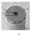
- the winding core 24 may be mechanically fixed to the case 12. Specifically, the center portion of the current collector 26 is welded to the end of the winding core 24 at weld 30, as shown in FIG. 4 .
- the weld 30 is preferably annular as shown, but may instead include individual welds at different locations around the interface between the current collector 26 and the winding core 24.
- the current collector 26 may be welded to the case 12 at weld 32 or any other convenient location where the current collector 26 contacts the case 12 to thereby mechanically fix the winding core 24 to the case 12.
- the winding core 24 is mechanically fixed to the case 12 directly welding the winding core 24 to the case 12.
- electrochemical cell 10 may not include a current collector disposed between direct weld of the winding core 24 to the case 12. By virtue of these designs, the electrode assembly 16 is securely retained in the case 12 to improve its resistance to shock and vibration.
- the welds 30 and 32 may be made by, for example, laser welding, but any welding technique would suffice.
- the current collector 26 may include an outer wall portion 34 that extends around the current collector 26 and has a diameter that is slightly larger than the inner diameter of the case 12. Prior to sealing the cover 14 to the top (first distal end) of the case 12, the top of the case 12 has an opening that is configured to receive the electrode assembly 16 and the current collector 26. When the current collector 26 is press-fit into the case 12, the current collector 26 radially displaces the case 12. In this manner, a pressure caused by the interference between the current collector 26 and the case 12 increases the inner diameter of the case 12 and decreases the diameter of the current collector 26. This further assists in stabilizing the electrode assembly 16 in the case 12.
- material 28 is provided around the outside of the jelly roll electrode assembly 16 such that it is sandwiched between the electrode assembly 16 and the case 12.
- the material 28 swells when the case 12 is filled with electrolyte to further secure the electrode assembly 16 in the case 12 and act as a cushion to shock or vibration.
- the material 28 may be such that when contacted by the electrolyte it also becomes sticky, thereby causing the electrode assembly 16 to adhere to the inner surface of the case 12 and further protect against high vibration and mechanical shock.
- the swellable material 28 examples include a highly soluble polymer material, such as, for example, polyvinyldifluride (PVdF), a polymer compound including a functional atom group such as an ester group and a carboxyl group, carboxymethylcellulose (CMC), styrene butadiene rubber (SBR latex), ethylene-propylene-diene methylene linkage (EPDM), etc.
- PVdF polyvinyldifluride
- CMC carboxymethylcellulose
- SBR latex styrene butadiene rubber
- EPDM ethylene-propylene-diene methylene linkage
- the material 28 may be applied to an outer circumference of the jelly roll electrode assembly 16.
- the material 28 may be considered to be a tape that is adhered to the electrode assembly 16.
- the material 28 may also be a coating material that coats an outer circumference of the electrode assembly 16.
- the material 28 may be applied to an inner surface of the case 12.
- the material 28 is considered to be a tape that is provided on an inner surface of the case 11 between the case 11 and the electrode assembly 16.
- the material 28 is considered to be a coating material that is coated on an inner surface of the case 11 between the case 11 and the electrode assembly 16.
- Exemplary embodiments described above are an improvement over the conventional electromechanical cells.
- the inventors conducted a vibration test which demonstrated that the conventional cell, without the above described weld 30 and swellable material 28, failed after fifteen seconds when vibrated to 54 G rms (root-mean-square acceleration) in a single direction.
- an exemplary electrochemical cell including the swellable material 28 and the current collector 26 welded to the winding core 24 at weld 30 survived six minutes under the same vibration parameters, well beyond a three minute per vibration direction threshold needed in some high vibration applications.
- lithium ion cells were vibration tested in the Z (parallel to the axis of the cell) axis to a customer-specific profile with amplitude 54 G rms .
- the cells were mounted into a rigid aluminum block by way of resin potting thereby connecting the cell case wall to the rigid block.
- the rigid block was then mounted directly to a vibration armature and the testing was completed at room temperature.
- the fixtures and cells were affixed with accelerometers, where possible, and the cells were monitored for voltage drop during the test in order to determine if a disconnect had occurred within the cell. The testing was continued for 3 minutes in the Z axis or until a failure occurred.
- each of the exemplary electrochemical cells was able to withstand the 3 minutes of 54 G rms vibration testing in each of three mutually-perpendicular axes. During this testing at three minutes per axis, the exemplary electrochemical cells did not show voltage fluctuations which would indicate a cell disconnect internally.
Landscapes
- Chemical & Material Sciences (AREA)
- Chemical Kinetics & Catalysis (AREA)
- Electrochemistry (AREA)
- General Chemical & Material Sciences (AREA)
- Engineering & Computer Science (AREA)
- Manufacturing & Machinery (AREA)
- Materials Engineering (AREA)
- Secondary Cells (AREA)
- Electric Double-Layer Capacitors Or The Like (AREA)
- Connection Of Batteries Or Terminals (AREA)
Abstract
Description
- The current disclosure relates to an electrochemical cell, including, without limitation, an electrochemical cell that is drop and vibration resistant.
- The background description provided herein is for the purpose of generally presenting the context of the disclosure. Work of the presently named inventors, to the extent it is described in this background section, as well as aspects of the description that may not otherwise qualify as prior art at the time of filing, are neither expressly nor impliedly admitted as prior art against the present disclosure.
- Some conventional electrochemical cells include an electrode assembly (jelly roll) disposed inside of a case. These types of cells are vulnerable to various mechanical abuses, in particular shock and vibration.
- That is, in certain applications, electrochemical cells are exposed to very high levels of vibration and/or mechanical shock, e.g. a space shuttle launching process. Such vibration or shock may cause the electrode assembly to move within the case causing the cell to fail due to, for example, breakage of welds within the cell, damage to the electrode material, bulging of the case and electrolyte leakage.
- The present invention provides a drop and vibration resistant lithium ion battery that is able to survive severe vibration and mechanical shock conditions.
- A first exemplary aspect of the present disclosure includes an electrochemical cell including an electrode assembly including a winding core, a first electrode, a second electrode, and a separator, the first electrode, the second electrode, and the separator being wound around the winding core, a current collector connected to the first electrode, a case that accommodates the wound electrode assembly and the current collector. The winding core is welded to the current collector which may be welded to the case.
- A second exemplary aspect of the present disclosure includes an electrochemical cell including a winding core extending in an axial direction, an electrode assembly including a first electrode and a second electrode wound around an outer circumference of the winding core, the wound electrode assembly having a first diameter, a case extending in the axial direction and having a second diameter that is greater than the first diameter, the case being configured to accommodate the wound electrode assembly. The winding core is mechanically fixed to the case.
- A third exemplary aspect of the present disclosure includes a method of making an electrochemical cell. The method includes welding a current collector to a winding core of an electrode assembly, inserting the wound electrode assembly into a case, and disposing a material, which swells, between the current collector and the case.
-
-
FIG. 1 shows a perspective view of an electrochemical cell according to an exemplary embodiment; -
FIG. 2 shows a partial cross-sectional view of a bottom portion of the electrochemical cell shown inFIG. 1 ; -
FIG. 3 shows a partial cross-sectional view of electrodes and separators for an electrochemical cell according to an exemplary embodiment; and -
FIG 4 shows a detailed view of a current collector welded to the winding core according to an exemplary embodiment. - Embodiments will be described below in more detail with reference to the accompanying drawings. The following detailed descriptions are provided to assist the reader in gaining a comprehensive understanding of the methods, apparatuses, and/or systems described herein and equivalent modifications thereof. Accordingly, various changes, modifications, and equivalents of the methods, apparatuses, and/or systems described herein will be apparent to those of ordinary skill in the art. Moreover, descriptions of well-known functions and constructions may be omitted for increased clarity and conciseness.
- The terms used in the description are intended to describe embodiments only, and shall by no means be restrictive. Unless clearly used otherwise, expressions in a singular form include a meaning of a plural form. In the present description, an expression such as "comprising" or "including" is intended to designate a characteristic, a number, a step, an operation, an element, a part or combinations thereof, and shall not be construed to preclude any presence or possibility of one or more other characteristics, numbers, steps, operations, elements, parts or combinations thereof.
-
FIG. 1 shows a perspective view of an exemplaryelectrochemical cell 10. According to an exemplary embodiment, thecell 10 includes a container orcase 12, a cap orcover 14, and a winding core ormandrel 24, and anelectrode assembly 16 wound around the windingcore 24. - The
electrode assembly 16 is a wound electrode assembly, commonly known as a jelly roll, which includes at least one cathode orpositive electrode 18, at least one anode ornegative electrode 20, and one ormore separators 22 that are wrapped around the windingcore 24. The one ormore separators 22 are provided intermediate or between the positive andnegative electrodes cell 10 includes an electrolyte (not shown) within thecase 12. In addition, to securely retain theelectrode assembly 16 in thecase 12, the windingcore 24 is welded to the current collector or bussingwasher 26, as illustrated inFIG. 2 . Also, amaterial 28, which swells when contacted by the electrolyte, may be provided between the outside of theelectrode assembly 16 and the inside wall of thecase 12 to snugly retain theelectrode assembly 16 in thecase 12. This aspect of the invention is discussed in greater detail below. - Although the winding
core 24 is shown as being provided as having a generally cylindrical shape, according to other exemplary embodiments, the windingcore 24 may have a different configuration (e.g., it may have an oval or rectangular cross-section shape, etc.). It is noted that theelectrode assembly 16, although shown as having a generally cylindrical shape, may also have a different configuration (e.g., it may have an oval, rectangular, or other desired cross-section shape). - The
positive electrode 18 is offset from thenegative electrode 20 in the axial direction as shown in the partial cross-sectional view shown inFIG. 3 . Accordingly, at a first end of theelectrode assembly 16, the woundpositive electrode 18 will extend further than thenegative electrode 20, and at a second (opposite) end of theelectrode assembly 16, thenegative electrode 20 will extend further than thepositive electrode 18. Accordingly, that current collectors may be connected to a specific electrode at one end of the cell without contacting the opposite polarity electrode. -
FIG. 2 shows a partial cross-sectional view of the closed bottom portion of theelectrochemical cell 10 including thecurrent collector 26. Thecurrent collector 26 has an annular shape and fits over the end of theelectrode assembly 16 such that it contacts either thepositive electrode 18 ornegative electrode 20 extending from theelectrode assembly 16. The windingcore 24 may be mechanically fixed to thecase 12. Specifically, the center portion of thecurrent collector 26 is welded to the end of the windingcore 24 atweld 30, as shown inFIG. 4 . Theweld 30 is preferably annular as shown, but may instead include individual welds at different locations around the interface between thecurrent collector 26 and thewinding core 24. In addition, thecurrent collector 26 may be welded to thecase 12 atweld 32 or any other convenient location where thecurrent collector 26 contacts thecase 12 to thereby mechanically fix the windingcore 24 to thecase 12. Furthermore, in another exemplary embodiment, thewinding core 24 is mechanically fixed to thecase 12 directly welding the windingcore 24 to thecase 12. In this exemplary embodiment,electrochemical cell 10 may not include a current collector disposed between direct weld of the windingcore 24 to thecase 12. By virtue of these designs, theelectrode assembly 16 is securely retained in thecase 12 to improve its resistance to shock and vibration. Thewelds - According to another exemplary embodiment, the
current collector 26 may include anouter wall portion 34 that extends around thecurrent collector 26 and has a diameter that is slightly larger than the inner diameter of thecase 12. Prior to sealing thecover 14 to the top (first distal end) of thecase 12, the top of thecase 12 has an opening that is configured to receive theelectrode assembly 16 and thecurrent collector 26. When thecurrent collector 26 is press-fit into thecase 12, thecurrent collector 26 radially displaces thecase 12. In this manner, a pressure caused by the interference between thecurrent collector 26 and thecase 12 increases the inner diameter of thecase 12 and decreases the diameter of thecurrent collector 26. This further assists in stabilizing theelectrode assembly 16 in thecase 12. - As noted above,
material 28 is provided around the outside of the jellyroll electrode assembly 16 such that it is sandwiched between theelectrode assembly 16 and thecase 12. Thematerial 28 swells when thecase 12 is filled with electrolyte to further secure theelectrode assembly 16 in thecase 12 and act as a cushion to shock or vibration. Thematerial 28 may be such that when contacted by the electrolyte it also becomes sticky, thereby causing theelectrode assembly 16 to adhere to the inner surface of thecase 12 and further protect against high vibration and mechanical shock. - Examples of the
swellable material 28 include a highly soluble polymer material, such as, for example, polyvinyldifluride (PVdF), a polymer compound including a functional atom group such as an ester group and a carboxyl group, carboxymethylcellulose (CMC), styrene butadiene rubber (SBR latex), ethylene-propylene-diene methylene linkage (EPDM), etc. - The
material 28 may be applied to an outer circumference of the jellyroll electrode assembly 16. For example, according to one exemplary embodiment, thematerial 28 may be considered to be a tape that is adhered to theelectrode assembly 16. Alternatively, thematerial 28 may also be a coating material that coats an outer circumference of theelectrode assembly 16. - According to other exemplary embodiments, the
material 28 may be applied to an inner surface of thecase 12. For example, according to one exemplary embodiment, thematerial 28 is considered to be a tape that is provided on an inner surface of the case 11 between the case 11 and theelectrode assembly 16. According to another exemplary embodiment, thematerial 28 is considered to be a coating material that is coated on an inner surface of the case 11 between the case 11 and theelectrode assembly 16. - Exemplary embodiments described above are an improvement over the conventional electromechanical cells. For example, the inventors conducted a vibration test which demonstrated that the conventional cell, without the above described
weld 30 andswellable material 28, failed after fifteen seconds when vibrated to 54 Grms (root-mean-square acceleration) in a single direction. In contrast, an exemplary electrochemical cell including theswellable material 28 and thecurrent collector 26 welded to the windingcore 24 atweld 30 survived six minutes under the same vibration parameters, well beyond a three minute per vibration direction threshold needed in some high vibration applications. - More specifically, lithium ion cells were vibration tested in the Z (parallel to the axis of the cell) axis to a customer-specific profile with amplitude 54 Grms. The cells were mounted into a rigid aluminum block by way of resin potting thereby connecting the cell case wall to the rigid block. The rigid block was then mounted directly to a vibration armature and the testing was completed at room temperature. The fixtures and cells were affixed with accelerometers, where possible, and the cells were monitored for voltage drop during the test in order to determine if a disconnect had occurred within the cell. The testing was continued for 3 minutes in the Z axis or until a failure occurred. If no failure occurred, the testing was repeated for X and Y axes (perpendicular axes perpendicular to the axis of the cell). Conventional cells without the above-mentioned features failed due to electrical disconnect consistently at roughly 15 seconds into the vibration testing. Constraining the top and bottom of the conventional cells externally (mimicking a thick cover and case bottom) extended the runtime to two minutes (120 seconds) when implemented on a conventional cell (still not meeting the 3 minute requirement needed in some high vibration applications). However, when the above-mentioned vibration testing was implemented on multiple exemplary electrochemical cells, each including the
swellable material 28 and thecurrent collector 26 welded to the windingcore 24 atweld 30, each saw an in increase in longevity without electrical disconnect during the vibration testing. Specifically, each of the exemplary electrochemical cells was able to withstand the 3 minutes of 54 G rms vibration testing in each of three mutually-perpendicular axes. During this testing at three minutes per axis, the exemplary electrochemical cells did not show voltage fluctuations which would indicate a cell disconnect internally. - Although the inventive concept has been described above with respect to the various embodiments, it is noted that there can be a variety of permutations and modifications of the described features by those who are familiar with this field, without departing from the technical ideas and scope of the features, which shall be defined by the appended claims.
- Further, while this specification contains many features, the features should not be construed as limitations on the scope of the disclosure or the appended claims. Certain features described in the context of separate embodiments can also be implemented in combination. Conversely, various features described in the context of a single embodiment can also be implemented in multiple embodiments separately or in any suitable subcombination.
Claims (19)
- An electrochemical cell comprising:an electrode assembly comprising a winding core, a first electrode, a second electrode, and a separator, the first electrode, the second electrode and the separator being wound around the winding core;a current collector connected to the first electrode; anda case that accommodates the wound electrode assembly and the current collector,wherein the winding core is welded to the current collector.
- The electrochemical cell according to claim 1
wherein the current collector is welded to the case. - The electrochemical cell according to claim 1, further comprising a material disposed between an inner surface of the case and the wound electrode assembly, wherein
the material swells in response to the case being filled with electrolyte. - The electrochemical cell according to claim 3, wherein the material is a tape wrapped around the wound electrode assembly that adheres to the case in response to being contacted by the electrolyte.
- The electrochemical cell according to claim 3, wherein the material coats an outer circumference of the wound electrode assembly.
- The electrochemical cell according to claim 5, wherein the material adheres to the case in response to being contacted by the electrolyte.
- The electrochemical cell according to claim 1, wherein the current collector includes an outer edge that is distal to the weld between the current collector and the winding core.
- The electrochemical cell according to claim 1, wherein the case includes a first distal end having an opening that is configured to receive the wound electrode assembly and the current collector, and the current collector radially displaces the case when the current collector is inserted into the case.
- The electrochemical cell according to claim 8, wherein the current collector has a circumference that is greater than a circumference of the wound electrode assembly and less than a circumference of an inner portion of the case.
- An electrochemical cell including:a winding core extending in an axial direction;an electrode assembly including a first electrode and a second electrode wound around an outer circumference of the winding core, the wound electrode assembly having a first diameter;a case extending in the axial direction and having a second diameter that is greater than the first diameter, the case being configured to accommodate the wound electrode assembly; andwherein the winding core is mechanically fixed to the case.
- The electrochemical cell according to claim 10, further comprising:a material disposed between the wound electrode assembly and the case, whereinin response to electrolyte being introduced into the case, the material swells and causes the wound electrode assembly to adhere to an inner surface of the case.
- The electrochemical cell according to claim 10, further comprising a current collector welded to the winding core.
- The electrochemical cell according to claim 12, wherein the current collector is further welded to an inner surface of the case to thereby mechanically fix the winding core to the case.
- A method of making an electrochemical cell, the method comprising:welding a current collector to a winding core of an electrode assembly;inserting the wound electrode assembly into a case; anddisposing a material, which swells between the current collector and the case.
- The method of making an electrochemical cell according to claim 14, wherein the material becomes adhesive in response to electrolyte.
- The method of making an electrochemical cell according to claim 14, wherein disposing the material comprises applying the material to the wound electrode assembly.
- The method of making an electrochemical cell according to claim 14, wherein disposing the material comprises applying the material to an inner surface of the case.
- The method of making an electrochemical cell according to claim 14, wherein the current collector has a diameter that is greater than an inner diameter of the case, and
inserting the wound electrode assembly into the case comprises press-fitting the wound electrode assembly into the case so that the current collector radially displaces the case. - The method of making an electrochemical cell according to claim 14, further comprising welding the current collector to an inner surface of the case.
Applications Claiming Priority (1)
| Application Number | Priority Date | Filing Date | Title |
|---|---|---|---|
| US13/835,263 US20140272503A1 (en) | 2013-03-15 | 2013-03-15 | Drop and vibration resistant electrochemical cell |
Publications (2)
| Publication Number | Publication Date |
|---|---|
| EP2779300A1 true EP2779300A1 (en) | 2014-09-17 |
| EP2779300B1 EP2779300B1 (en) | 2018-05-30 |
Family
ID=50231064
Family Applications (1)
| Application Number | Title | Priority Date | Filing Date |
|---|---|---|---|
| EP14158349.2A Active EP2779300B1 (en) | 2013-03-15 | 2014-03-07 | Drop and vibration resistant electrochemical cell |
Country Status (2)
| Country | Link |
|---|---|
| US (1) | US20140272503A1 (en) |
| EP (1) | EP2779300B1 (en) |
Families Citing this family (2)
| Publication number | Priority date | Publication date | Assignee | Title |
|---|---|---|---|---|
| KR102530339B1 (en) * | 2022-01-19 | 2023-05-09 | 삼성에스디아이 주식회사 | Secondary battery |
| DE102023105251A1 (en) * | 2023-03-03 | 2024-09-05 | Bayerische Motoren Werke Aktiengesellschaft | Battery and method for producing the battery |
Citations (2)
| Publication number | Priority date | Publication date | Assignee | Title |
|---|---|---|---|---|
| JP2011238569A (en) * | 2010-05-13 | 2011-11-24 | Toyota Motor Corp | Battery, vehicle and battery-equipped device |
| WO2012102586A2 (en) * | 2011-01-27 | 2012-08-02 | 주식회사 엘지화학 | Tape |
Family Cites Families (7)
| Publication number | Priority date | Publication date | Assignee | Title |
|---|---|---|---|---|
| US4315060A (en) * | 1980-06-13 | 1982-02-09 | Gte Products Corporation | Metal substrate for an electrochemical cell |
| US6214490B1 (en) * | 1998-12-17 | 2001-04-10 | Eveready Battery Company, Inc. | Foam collector for electrochemical cells |
| JP3738230B2 (en) * | 2002-01-15 | 2006-01-25 | 松下電器産業株式会社 | Battery manufacturing method |
| US20080254354A1 (en) * | 2007-04-11 | 2008-10-16 | Saft | Connection system for an electrochemical cell |
| JP5132269B2 (en) * | 2007-11-13 | 2013-01-30 | 日立ビークルエナジー株式会社 | Lithium ion secondary battery |
| US20120141849A1 (en) * | 2010-12-07 | 2012-06-07 | E-One Moli Energy (Canada) Limited | Drop and Vibration Resistant Lithium-Ion Battery |
| KR20140002460A (en) * | 2011-03-16 | 2014-01-08 | 파나소닉 주식회사 | Wound type battery and method for fabricating same |
-
2013
- 2013-03-15 US US13/835,263 patent/US20140272503A1/en not_active Abandoned
-
2014
- 2014-03-07 EP EP14158349.2A patent/EP2779300B1/en active Active
Patent Citations (2)
| Publication number | Priority date | Publication date | Assignee | Title |
|---|---|---|---|---|
| JP2011238569A (en) * | 2010-05-13 | 2011-11-24 | Toyota Motor Corp | Battery, vehicle and battery-equipped device |
| WO2012102586A2 (en) * | 2011-01-27 | 2012-08-02 | 주식회사 엘지화학 | Tape |
Also Published As
| Publication number | Publication date |
|---|---|
| US20140272503A1 (en) | 2014-09-18 |
| EP2779300B1 (en) | 2018-05-30 |
Similar Documents
| Publication | Publication Date | Title |
|---|---|---|
| US9490079B2 (en) | Electrochemical energy storage device with flexible metal contact current collector and methods of manufacture | |
| US10693195B2 (en) | Rechargeable battery | |
| JP7654042B2 (en) | Wound secondary battery and its manufacturing method | |
| CN102859747A (en) | Secondary battery | |
| KR20120121220A (en) | Rechargeable battery | |
| EP2913868A1 (en) | Secondary battery and method of manufacturing the same | |
| JP2018525781A (en) | Lithium rechargeable battery with integrated circuit breaker to improve operational safety | |
| CA2131777A1 (en) | Sealed electrical device with unitary fill port and terminal construction | |
| US20240213497A1 (en) | Battery Cell and Method for Producing a Battery Cell | |
| JP6984653B2 (en) | Square secondary battery and assembled battery using it | |
| KR20160031640A (en) | Rechargeable battery | |
| CN111987379A (en) | Lithium ion battery with reference electrode and preparation method thereof | |
| EP2779300B1 (en) | Drop and vibration resistant electrochemical cell | |
| KR20100002633A (en) | The cylindrical storage battery | |
| KR102283784B1 (en) | Rechargeable battery | |
| KR102275331B1 (en) | Rechargeable battery | |
| KR20130054946A (en) | Electrolytic capacitor and method for manufacturing electrolytic capacitor | |
| KR101958762B1 (en) | Cylindrical secondary battery | |
| EP3518335B1 (en) | Lithium secondary battery including cylindrical jelly roll | |
| JP6606400B2 (en) | Electricity storage element | |
| US20250364707A1 (en) | Energy storage device and state detection method for energy storage device | |
| WO2024057631A1 (en) | Battery | |
| KR100998847B1 (en) | Beading prosthetic member and cylindrical battery including the same | |
| JPWO2022071079A5 (en) | ||
| CN223514190U (en) | Power storage battery cell |
Legal Events
| Date | Code | Title | Description |
|---|---|---|---|
| 17P | Request for examination filed |
Effective date: 20140307 |
|
| AK | Designated contracting states |
Kind code of ref document: A1 Designated state(s): AL AT BE BG CH CY CZ DE DK EE ES FI FR GB GR HR HU IE IS IT LI LT LU LV MC MK MT NL NO PL PT RO RS SE SI SK SM TR |
|
| AX | Request for extension of the european patent |
Extension state: BA ME |
|
| PUAI | Public reference made under article 153(3) epc to a published international application that has entered the european phase |
Free format text: ORIGINAL CODE: 0009012 |
|
| R17P | Request for examination filed (corrected) |
Effective date: 20150316 |
|
| RBV | Designated contracting states (corrected) |
Designated state(s): AL AT BE BG CH CY CZ DE DK EE ES FI FR GB GR HR HU IE IS IT LI LT LU LV MC MK MT NL NO PL PT RO RS SE SI SK SM TR |
|
| 17Q | First examination report despatched |
Effective date: 20160914 |
|
| STAA | Information on the status of an ep patent application or granted ep patent |
Free format text: STATUS: EXAMINATION IS IN PROGRESS |
|
| RIC1 | Information provided on ipc code assigned before grant |
Ipc: C09J 201/00 20060101ALI20171215BHEP Ipc: C09J 7/02 00000000ALI20171215BHEP Ipc: H01M 2/26 20060101ALI20171215BHEP Ipc: H01M 10/04 20060101ALI20171215BHEP Ipc: H01M 10/0587 20100101AFI20171215BHEP Ipc: H01M 10/0525 20100101ALI20171215BHEP |
|
| GRAP | Despatch of communication of intention to grant a patent |
Free format text: ORIGINAL CODE: EPIDOSNIGR1 |
|
| STAA | Information on the status of an ep patent application or granted ep patent |
Free format text: STATUS: GRANT OF PATENT IS INTENDED |
|
| RIC1 | Information provided on ipc code assigned before grant |
Ipc: H01M 10/04 20060101ALI20180116BHEP Ipc: H01M 2/26 20060101ALI20180116BHEP Ipc: H01M 10/0525 20100101ALI20180116BHEP Ipc: H01M 10/0587 20100101AFI20180116BHEP |
|
| INTG | Intention to grant announced |
Effective date: 20180201 |
|
| GRAS | Grant fee paid |
Free format text: ORIGINAL CODE: EPIDOSNIGR3 |
|
| GRAA | (expected) grant |
Free format text: ORIGINAL CODE: 0009210 |
|
| STAA | Information on the status of an ep patent application or granted ep patent |
Free format text: STATUS: THE PATENT HAS BEEN GRANTED |
|
| AK | Designated contracting states |
Kind code of ref document: B1 Designated state(s): AL AT BE BG CH CY CZ DE DK EE ES FI FR GB GR HR HU IE IS IT LI LT LU LV MC MK MT NL NO PL PT RO RS SE SI SK SM TR |
|
| REG | Reference to a national code |
Ref country code: GB Ref legal event code: FG4D |
|
| REG | Reference to a national code |
Ref country code: CH Ref legal event code: EP |
|
| REG | Reference to a national code |
Ref country code: AT Ref legal event code: REF Ref document number: 1004539 Country of ref document: AT Kind code of ref document: T Effective date: 20180615 |
|
| REG | Reference to a national code |
Ref country code: IE Ref legal event code: FG4D |
|
| REG | Reference to a national code |
Ref country code: DE Ref legal event code: R096 Ref document number: 602014026061 Country of ref document: DE |
|
| REG | Reference to a national code |
Ref country code: NL Ref legal event code: MP Effective date: 20180530 |
|
| REG | Reference to a national code |
Ref country code: LT Ref legal event code: MG4D |
|
| PG25 | Lapsed in a contracting state [announced via postgrant information from national office to epo] |
Ref country code: ES Free format text: LAPSE BECAUSE OF FAILURE TO SUBMIT A TRANSLATION OF THE DESCRIPTION OR TO PAY THE FEE WITHIN THE PRESCRIBED TIME-LIMIT Effective date: 20180530 Ref country code: NO Free format text: LAPSE BECAUSE OF FAILURE TO SUBMIT A TRANSLATION OF THE DESCRIPTION OR TO PAY THE FEE WITHIN THE PRESCRIBED TIME-LIMIT Effective date: 20180830 Ref country code: SE Free format text: LAPSE BECAUSE OF FAILURE TO SUBMIT A TRANSLATION OF THE DESCRIPTION OR TO PAY THE FEE WITHIN THE PRESCRIBED TIME-LIMIT Effective date: 20180530 Ref country code: CY Free format text: LAPSE BECAUSE OF FAILURE TO SUBMIT A TRANSLATION OF THE DESCRIPTION OR TO PAY THE FEE WITHIN THE PRESCRIBED TIME-LIMIT Effective date: 20180530 Ref country code: LT Free format text: LAPSE BECAUSE OF FAILURE TO SUBMIT A TRANSLATION OF THE DESCRIPTION OR TO PAY THE FEE WITHIN THE PRESCRIBED TIME-LIMIT Effective date: 20180530 Ref country code: FI Free format text: LAPSE BECAUSE OF FAILURE TO SUBMIT A TRANSLATION OF THE DESCRIPTION OR TO PAY THE FEE WITHIN THE PRESCRIBED TIME-LIMIT Effective date: 20180530 Ref country code: BG Free format text: LAPSE BECAUSE OF FAILURE TO SUBMIT A TRANSLATION OF THE DESCRIPTION OR TO PAY THE FEE WITHIN THE PRESCRIBED TIME-LIMIT Effective date: 20180830 |
|
| PG25 | Lapsed in a contracting state [announced via postgrant information from national office to epo] |
Ref country code: RS Free format text: LAPSE BECAUSE OF FAILURE TO SUBMIT A TRANSLATION OF THE DESCRIPTION OR TO PAY THE FEE WITHIN THE PRESCRIBED TIME-LIMIT Effective date: 20180530 Ref country code: LV Free format text: LAPSE BECAUSE OF FAILURE TO SUBMIT A TRANSLATION OF THE DESCRIPTION OR TO PAY THE FEE WITHIN THE PRESCRIBED TIME-LIMIT Effective date: 20180530 Ref country code: GR Free format text: LAPSE BECAUSE OF FAILURE TO SUBMIT A TRANSLATION OF THE DESCRIPTION OR TO PAY THE FEE WITHIN THE PRESCRIBED TIME-LIMIT Effective date: 20180831 Ref country code: HR Free format text: LAPSE BECAUSE OF FAILURE TO SUBMIT A TRANSLATION OF THE DESCRIPTION OR TO PAY THE FEE WITHIN THE PRESCRIBED TIME-LIMIT Effective date: 20180530 |
|
| REG | Reference to a national code |
Ref country code: AT Ref legal event code: MK05 Ref document number: 1004539 Country of ref document: AT Kind code of ref document: T Effective date: 20180530 |
|
| PG25 | Lapsed in a contracting state [announced via postgrant information from national office to epo] |
Ref country code: NL Free format text: LAPSE BECAUSE OF FAILURE TO SUBMIT A TRANSLATION OF THE DESCRIPTION OR TO PAY THE FEE WITHIN THE PRESCRIBED TIME-LIMIT Effective date: 20180530 |
|
| PG25 | Lapsed in a contracting state [announced via postgrant information from national office to epo] |
Ref country code: SK Free format text: LAPSE BECAUSE OF FAILURE TO SUBMIT A TRANSLATION OF THE DESCRIPTION OR TO PAY THE FEE WITHIN THE PRESCRIBED TIME-LIMIT Effective date: 20180530 Ref country code: RO Free format text: LAPSE BECAUSE OF FAILURE TO SUBMIT A TRANSLATION OF THE DESCRIPTION OR TO PAY THE FEE WITHIN THE PRESCRIBED TIME-LIMIT Effective date: 20180530 Ref country code: EE Free format text: LAPSE BECAUSE OF FAILURE TO SUBMIT A TRANSLATION OF THE DESCRIPTION OR TO PAY THE FEE WITHIN THE PRESCRIBED TIME-LIMIT Effective date: 20180530 Ref country code: DK Free format text: LAPSE BECAUSE OF FAILURE TO SUBMIT A TRANSLATION OF THE DESCRIPTION OR TO PAY THE FEE WITHIN THE PRESCRIBED TIME-LIMIT Effective date: 20180530 Ref country code: AT Free format text: LAPSE BECAUSE OF FAILURE TO SUBMIT A TRANSLATION OF THE DESCRIPTION OR TO PAY THE FEE WITHIN THE PRESCRIBED TIME-LIMIT Effective date: 20180530 Ref country code: PL Free format text: LAPSE BECAUSE OF FAILURE TO SUBMIT A TRANSLATION OF THE DESCRIPTION OR TO PAY THE FEE WITHIN THE PRESCRIBED TIME-LIMIT Effective date: 20180530 Ref country code: CZ Free format text: LAPSE BECAUSE OF FAILURE TO SUBMIT A TRANSLATION OF THE DESCRIPTION OR TO PAY THE FEE WITHIN THE PRESCRIBED TIME-LIMIT Effective date: 20180530 |
|
| REG | Reference to a national code |
Ref country code: CH Ref legal event code: PK Free format text: BERICHTIGUNGEN |
|
| RIC2 | Information provided on ipc code assigned after grant |
Ipc: H01M 2/26 20060101ALI20180116BHEP Ipc: H01M 10/0587 20100101AFI20180116BHEP Ipc: H01M 10/0525 20100101ALI20180116BHEP Ipc: H01M 10/04 20060101ALI20180116BHEP |
|
| PG25 | Lapsed in a contracting state [announced via postgrant information from national office to epo] |
Ref country code: SM Free format text: LAPSE BECAUSE OF FAILURE TO SUBMIT A TRANSLATION OF THE DESCRIPTION OR TO PAY THE FEE WITHIN THE PRESCRIBED TIME-LIMIT Effective date: 20180530 Ref country code: IT Free format text: LAPSE BECAUSE OF FAILURE TO SUBMIT A TRANSLATION OF THE DESCRIPTION OR TO PAY THE FEE WITHIN THE PRESCRIBED TIME-LIMIT Effective date: 20180530 |
|
| REG | Reference to a national code |
Ref country code: DE Ref legal event code: R097 Ref document number: 602014026061 Country of ref document: DE |
|
| PLBE | No opposition filed within time limit |
Free format text: ORIGINAL CODE: 0009261 |
|
| STAA | Information on the status of an ep patent application or granted ep patent |
Free format text: STATUS: NO OPPOSITION FILED WITHIN TIME LIMIT |
|
| 26N | No opposition filed |
Effective date: 20190301 |
|
| PG25 | Lapsed in a contracting state [announced via postgrant information from national office to epo] |
Ref country code: SI Free format text: LAPSE BECAUSE OF FAILURE TO SUBMIT A TRANSLATION OF THE DESCRIPTION OR TO PAY THE FEE WITHIN THE PRESCRIBED TIME-LIMIT Effective date: 20180530 |
|
| PG25 | Lapsed in a contracting state [announced via postgrant information from national office to epo] |
Ref country code: MC Free format text: LAPSE BECAUSE OF FAILURE TO SUBMIT A TRANSLATION OF THE DESCRIPTION OR TO PAY THE FEE WITHIN THE PRESCRIBED TIME-LIMIT Effective date: 20180530 |
|
| REG | Reference to a national code |
Ref country code: CH Ref legal event code: PL |
|
| PG25 | Lapsed in a contracting state [announced via postgrant information from national office to epo] |
Ref country code: AL Free format text: LAPSE BECAUSE OF FAILURE TO SUBMIT A TRANSLATION OF THE DESCRIPTION OR TO PAY THE FEE WITHIN THE PRESCRIBED TIME-LIMIT Effective date: 20180530 Ref country code: LU Free format text: LAPSE BECAUSE OF NON-PAYMENT OF DUE FEES Effective date: 20190307 |
|
| REG | Reference to a national code |
Ref country code: BE Ref legal event code: MM Effective date: 20190331 |
|
| PG25 | Lapsed in a contracting state [announced via postgrant information from national office to epo] |
Ref country code: CH Free format text: LAPSE BECAUSE OF NON-PAYMENT OF DUE FEES Effective date: 20190331 Ref country code: IE Free format text: LAPSE BECAUSE OF NON-PAYMENT OF DUE FEES Effective date: 20190307 Ref country code: LI Free format text: LAPSE BECAUSE OF NON-PAYMENT OF DUE FEES Effective date: 20190331 |
|
| PG25 | Lapsed in a contracting state [announced via postgrant information from national office to epo] |
Ref country code: BE Free format text: LAPSE BECAUSE OF NON-PAYMENT OF DUE FEES Effective date: 20190331 |
|
| PG25 | Lapsed in a contracting state [announced via postgrant information from national office to epo] |
Ref country code: TR Free format text: LAPSE BECAUSE OF FAILURE TO SUBMIT A TRANSLATION OF THE DESCRIPTION OR TO PAY THE FEE WITHIN THE PRESCRIBED TIME-LIMIT Effective date: 20180530 |
|
| PG25 | Lapsed in a contracting state [announced via postgrant information from national office to epo] |
Ref country code: PT Free format text: LAPSE BECAUSE OF FAILURE TO SUBMIT A TRANSLATION OF THE DESCRIPTION OR TO PAY THE FEE WITHIN THE PRESCRIBED TIME-LIMIT Effective date: 20181001 Ref country code: MT Free format text: LAPSE BECAUSE OF NON-PAYMENT OF DUE FEES Effective date: 20190307 |
|
| PG25 | Lapsed in a contracting state [announced via postgrant information from national office to epo] |
Ref country code: IS Free format text: LAPSE BECAUSE OF FAILURE TO SUBMIT A TRANSLATION OF THE DESCRIPTION OR TO PAY THE FEE WITHIN THE PRESCRIBED TIME-LIMIT Effective date: 20180930 |
|
| PG25 | Lapsed in a contracting state [announced via postgrant information from national office to epo] |
Ref country code: HU Free format text: LAPSE BECAUSE OF FAILURE TO SUBMIT A TRANSLATION OF THE DESCRIPTION OR TO PAY THE FEE WITHIN THE PRESCRIBED TIME-LIMIT; INVALID AB INITIO Effective date: 20140307 |
|
| PG25 | Lapsed in a contracting state [announced via postgrant information from national office to epo] |
Ref country code: MK Free format text: LAPSE BECAUSE OF FAILURE TO SUBMIT A TRANSLATION OF THE DESCRIPTION OR TO PAY THE FEE WITHIN THE PRESCRIBED TIME-LIMIT Effective date: 20180530 |
|
| P01 | Opt-out of the competence of the unified patent court (upc) registered |
Effective date: 20230514 |
|
| PGFP | Annual fee paid to national office [announced via postgrant information from national office to epo] |
Ref country code: DE Payment date: 20250331 Year of fee payment: 12 |
|
| PGFP | Annual fee paid to national office [announced via postgrant information from national office to epo] |
Ref country code: GB Payment date: 20260331 Year of fee payment: 13 |
|
| PGFP | Annual fee paid to national office [announced via postgrant information from national office to epo] |
Ref country code: FR Payment date: 20260327 Year of fee payment: 13 |