EP2779144A1 - Device for simulating blood flow - Google Patents
Device for simulating blood flow Download PDFInfo
- Publication number
- EP2779144A1 EP2779144A1 EP13158858.4A EP13158858A EP2779144A1 EP 2779144 A1 EP2779144 A1 EP 2779144A1 EP 13158858 A EP13158858 A EP 13158858A EP 2779144 A1 EP2779144 A1 EP 2779144A1
- Authority
- EP
- European Patent Office
- Prior art keywords
- flow
- pump
- hydraulic circuit
- average
- pulsating
- Prior art date
- Legal status (The legal status is an assumption and is not a legal conclusion. Google has not performed a legal analysis and makes no representation as to the accuracy of the status listed.)
- Granted
Links
Images

Classifications
-
- G—PHYSICS
- G09—EDUCATION; CRYPTOGRAPHY; DISPLAY; ADVERTISING; SEALS
- G09B—EDUCATIONAL OR DEMONSTRATION APPLIANCES; APPLIANCES FOR TEACHING, OR COMMUNICATING WITH, THE BLIND, DEAF OR MUTE; MODELS; PLANETARIA; GLOBES; MAPS; DIAGRAMS
- G09B23/00—Models for scientific, medical, or mathematical purposes, e.g. full-sized devices for demonstration purposes
- G09B23/28—Models for scientific, medical, or mathematical purposes, e.g. full-sized devices for demonstration purposes for medicine
-
- A—HUMAN NECESSITIES
- A61—MEDICAL OR VETERINARY SCIENCE; HYGIENE
- A61B—DIAGNOSIS; SURGERY; IDENTIFICATION
- A61B5/00—Measuring for diagnostic purposes; Identification of persons
- A61B5/02—Detecting, measuring or recording for evaluating the cardiovascular system, e.g. pulse, heart rate, blood pressure or blood flow
- A61B5/02007—Evaluating blood vessel condition, e.g. elasticity, compliance
- A61B5/02014—Determining aneurysm
-
- A—HUMAN NECESSITIES
- A61—MEDICAL OR VETERINARY SCIENCE; HYGIENE
- A61B—DIAGNOSIS; SURGERY; IDENTIFICATION
- A61B5/00—Measuring for diagnostic purposes; Identification of persons
- A61B5/02—Detecting, measuring or recording for evaluating the cardiovascular system, e.g. pulse, heart rate, blood pressure or blood flow
- A61B5/021—Measuring pressure in heart or blood vessels
-
- A—HUMAN NECESSITIES
- A61—MEDICAL OR VETERINARY SCIENCE; HYGIENE
- A61B—DIAGNOSIS; SURGERY; IDENTIFICATION
- A61B5/00—Measuring for diagnostic purposes; Identification of persons
- A61B5/02—Detecting, measuring or recording for evaluating the cardiovascular system, e.g. pulse, heart rate, blood pressure or blood flow
- A61B5/026—Measuring blood flow
Definitions
- the present invention is related to a device for in vitro simulating blood flow in vessels.
- the present invention may be used to study biological events, and in particular, pathological diseases related to blood flow such as cardiac diseases, including atherosclerosis and spontaneous or stent-induced thrombosis in intracranial aneurysms.
- cardiac diseases including atherosclerosis and spontaneous or stent-induced thrombosis in intracranial aneurysms.
- the present invention may be used to study flow phenomena in different geometry of vessels such as straight pipes, bifurcations as well as different type of more complex vessel geometries (aneurysms, stenosis).
- the present invention may be used to study flow phenomena effect in aneurysms or stenosis with a mesh 'tube' inserted, called the stent.
- the present invention may be used to test the effect of potential drugs or other molecules or compositions.
- An aneurysm is a bubble-like extension of the wall of a blood vessel provoked usually by pathologies or mechanic disturbances of the blood flow. Aneurysms are considered dangerous because they can rupture and provoke internal haemorrhages that can lead to a stroke and even dead.
- Cardiovascular diseases and in particular atherosclerosis, are known to be among the main causes of mortality and morbidity in the world, especially in developed countries.
- Atherosclerosis is a chronic inflammatory disease of large and medium arteries, leading to the accumulation of cholesterol and white blood cells at the subendothelial level in the blood vessels, thereby resulting into the thickening of the wall and the narrowing of the lumen. It may be accompanied by complications, such as a myocardial infraction or thrombosis, with sudden hemostatic blockage inside a blood vessel
- a device offering a realistic in vitro model based on numerical simulation of human blood flows in vessels would then be very useful for studying this pathology and for testing potential solutions, and in particular potentially active substances, and would be an attractive alternative to in vivo testing.
- An aim of the invention is to reproduce particular parts of circulatory system together with the physiological conditions as precisely as possible. More particularly, an aim of the invention is to reproduce the flow conditions in a particular vessel.
- the present invention provides a device for in vitro simulation of blood flows.
- the liquid used for the simulation can be the whole blood (in that case, along with anti-clotting agent to avoid clotting in the device) or a suitable aqueous solution, preferably maintained to physiological pH, and preferably containing suitable nutrient.
- the present device is based on numerical simulation, and in particular on computational fluid dynamic (CFD) calculations.
- CFD computational fluid dynamic
- said device comprises a closed-loop hydraulic circuit for circulating a liquid from a reservoir through a test chamber in a pulsatile manner, whereby the liquid may be continuously recirculated through the device.
- the present invention is related to a closed-loop hydraulic circuit for in vitro simulation of blood flow and for testing the effect of such simulated flow on a biological sample, comprising:
- the present invention comprises one or a suitable combination of at least two of the following features:
- Another aspect of the invention is related to a cyclic method for regulating the flow in the system according to any of the previous claim, each cycle comprising the steps of:
- the adapting steps are performed using proportional and integral (PI) regulation method.
- PI proportional and integral
- the pulsating pump is controlled by using an Internal Model Controller.
- the pulsating pump comprises a cylinder and a moving piston
- the cyclic method comprising the step of calculating the average position of the piston and comparing the calculated average position with the value calculated in the previous cycle, and adapting the constant flow pump rate in case of variation of said average position in order to avoid drifting of the piston position from one cycle to the next cycle.
- endothelial cells refer to the cells lining all blood vessels.
- Wall shear stress the fluid frictional force per unit of surface area. Wall shear stress acts along the blood vessel's longitudinal axis.
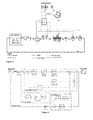
- Figure 1 represents a schematic view of a hydraulic circuit and sensors according to the invention.
- Figure 2 represents a schematic view of the regulation loops of an example of the invention.
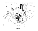
- Figure 3 represents a portable version of the closed-loop hydraulic circuit of the invention. This version is intended to be enclosed in a transparent box.
- Figure 4 represents the electrical parts controlling the hydraulic circuit.
- the device according to the present invention offers different technical advantages.
- the present device is useful in helping to determine how fluid dynamics modulates the response of endothelial cells under physiological conditions in an in vitro flow loop.
- the present device permits critical examination of the effects of critical flow parameters on endothelial cells on the surfaces of vessels.
- the present device simulates shear stress, the tangential frictional force acting in the direction of flow along a vessel's surface.
- the present device is adapted to reproduce different kinds of vessels, different either by their dimensions and/or by their geometry, with minor adaptations.
- This device is also adapted to different kinds of support measurement equipments including, but not limited to lasers such as for example Participle Image Velocimetry (PIV) lasers, scanners such as for example Computer Tomography (CT) scanners, microscopes such as Digital Holographic Microscopes.
- lasers such as for example Participle Image Velocimetry (PIV) lasers
- scanners such as for example Computer Tomography (CT) scanners
- microscopes such as Digital Holographic Microscopes.
- this device is easy to use, compact, mobile, as automatic as possible.
- At least the hydraulic part of this device may easily be sterilized, without any damage to its functioning, even after several sterilization cycles.
- the flow is splitted in a continuous component and a variable component having an average zero value.
- the splitted flow is then imposed by using a constant flow pump having an essentially constant flow rate (i.e. the variation is slow in comparison with the normal cycle time) and a pulsating pump having an average zero flow rate.
- a constant flow pump having an essentially constant flow rate (i.e. the variation is slow in comparison with the normal cycle time) and a pulsating pump having an average zero flow rate.
- Such combination of pumps is particularly suitable to reproduce a pulsating flow of liquid inside the closed circuit, such that a fluid-dynamic component is introduced into the system which makes the flow in the test chamber very similar to the conditions present in the coronary flows, reproducing in a reliable manner what happens in the vessel circuit in the vicinity of heart.
- splitting of the flow in an average component and a superimposed pulsating component makes the regulation easier by using separated regulation loops.
- a peristaltic pump or a centrifugal pump can be used.
- the peristaltic pump can drive a nearly constant mean flow rate. But by its working principle, based on the compression of a pipe by rotating round pebble, that peristaltic pump can destroy cells, like Red Blood Cells, by the rolling process of the pipe. Moreover, as it presses pipes, little pieces of them can be released to the system and make the medium toxic for the living cells.
- the peristaltic pump is a roller positive displacement pump that gives a flow rate oscillating around the mean flow rate. In order to reach a more constant flow rate it is necessary to add a second pump head or/and a compliance chamber. However, the compliance chamber incorporates more elasticity to the system and has a bad impact on the control capabilities.
- the centrifugal pump avoids that rolling inconvenient and can be used to provide the mean flow rate without destroying the cells if necessary for the use of real Red Blood Cells in the medium.
- the centrifugal pump is more influenced by movements of the piston pump: it has an impact of the pumping flow behaviour especially on the pick flow.
- Pumping means are adapted for altering and changing hemodynamic conditions (pressure and flow variables) in the loop so as to permit simulating the hemodynamic conditions to capillaries of the human circulatory system.
- the device comprises different controlling means: means for measuring, monitoring and controlling different flow conditions by creating, measuring, monitoring and controlling flow variables (paramaters) such as the fluid temperature, the fluid pressure, the fluid pulse characteristics (including pulse frequency, pulse width and more generally pulse waveform) and the flow rate through the device.
- flow variables such as the fluid temperature, the fluid pressure, the fluid pulse characteristics (including pulse frequency, pulse width and more generally pulse waveform) and the flow rate through the device.
- the liquid or fluid used in the present invention preferably comprises nutrients necessary to support metabolism of the living tissues present in the test chamber.
- the temperature of the liquid or fluid should preferably be maintained at about 37°C, and its pH at about 7.45.
- the overall performance of the device, and in particular of the loop should be preliminary tested to verify that the desired flow conditions can be achieved.
- circuit (the loop) is closed further offers the advantage to prevent any liquid leakage from the device, thereby reducing the risk of contamination to the operators, and increasing the overall conditions of cleanliness and hygiene.
- the response of endothelial cells are preferably monitored in the test chamber by acquisition of data, for example images, by optical acquisition means, which advantageously comprises at least a microscope, optionally connected to filming means such as for example a camera, and in particular a CCD camera.
- optical acquisition means advantageously comprises at least a microscope, optionally connected to filming means such as for example a camera, and in particular a CCD camera.
- the filming means comprises an integrated recording/acquisition system connected to electronic processing means, such as for example a digital computerized system with a memorized program.
- said memorized program is such that it is able, when executed in the computerized system, to analyze in real time biological parameters such as the morphological, kinetic, and biochemical variations inside and outside the endothelial cells in test chamber in response to different conditions of mechanical forces.
- the principle of the control loop is shown in Fig 2 .
- the reference signal is divided into two signals: the mean flow and the pulsatile fluctuations of the flow. From that division, we have two main controls.
- the mean flow is controlled by the PI controller number II and the function "mean II".
- the function "mean II” is responsible for calculating the mean flow at each cycle. It adds every point of the measured flow cycle and divides the latter by the number of the measured samples for this cycle. Then the signal is sent as a measured signal to the adder in order to compare with the mean reference value. Then the controller PI II set rotation of the centrifugal pump in order to get the desired mean flow rate (the transfer function G CP (s)). Thanks to the function "mean II" the control loop is less sensitive to disturbances on the mean flow, which helps to achieve the stability of the whole system.
- the second control loop is responsible for controlling the shape of the pulsatile flow. This loop is based on the Internal Model Control (Internal Model Control in the Fig.2 ) and is additional to the PI controller.
- the reference signal is compared with a measured signal and is sent to the internal controller Gc(s). After that, the controlled signal goes through a saturation block which sets the movement limits of the linear motor. The signal is then sent to the controller of the linear motor and drives the movements. Later the flow is read by the electromagnetic flowmeter that is presented in the Fig. 2 as a transfer function between position of the linear motor and flowmeter G P (s) and in addition read by model process G MP (s) in order to predict position of the linear motor.
- the signal is preferably treated by a filter F (used only in real-time process) and then compared with the actual position of the piston.
- a filter F used only in real-time process
- An additional filter is used because the noise of the read signal from electromagnetic flowmeter can be too high and the mean flow rate pumped by the centrifugal pump and read by the flowmeter is not perfectly constant and this may have influence on the controlled signal.
- an additional loop (Drift of the piston in the Fig.2 ) is advantageously incorporated into the regulation system. This loop calculates a mean position for every cycle separately and compares it with the mean position previously set. If there is any drift, the PI controller number II modifies the reference signal of the flow.
- the typical input signal x(t) used as the excitation signal is a sinusoidal wave (known also as a sweep signal or a chirp signal) with amplitude A and frequency ⁇ .
- the output signal y(t) coming from the system is also a sinusoidal wave but with different amplitude B, the same frequency ⁇ and a phase shift ⁇ between the input signals.
- the input signal is a position of the linear motor in volts which drives a piston pump with a diaphragm.
- the output signal is the flow read in volts. Based on the experimental data the magnitude and phase are then calculated.
- two methods may be used: one is to determine the zeros and poles of the system by observation of the experimental data; second is based on the known transfer function for which parameters can be found by used the parameter estimation function that can be used from the commercial software such as Simulink® Design OptimizationTM toolbox. Five orders transfer function with delay was are preferably used to get a sufficient fitting.
- the calculated transfer functions are then used to determine the parameters of an internal model controller used for controlling the pulsating component of the pulsating pump.
- FIG. 1 A preferred embodiment of the device according to the present invention is presented on Figure 1 .
- the closed-loop hydraulic circuit starts in an incubator 2 where a reservoir 1 with bio-medium is put in order to maintain the physiological condition (pH level at 7.45). This is done by keeping gas balance at the proper level i.e. CO2 5% in the air.
- the mean flow rate is pumped by a centrifugal pump 3 which is particularly designed to pump blood, for example BPX-80 Biopump (Medrotronic).
- the temperature level 37°C is read on the thermocouple 6. Just upstream of a test section 8, there is a pressure sensor 7 which measures the pressure inside the system.
- the test section 8 is on-line with a microscope 9 which is connected to a digital camera 10.
- the camera takes pictures of ECs while the system is working. After that, the flow rate is measured by a flowmeter 11.
- the last two pieces of equipment are solenoid proportional valves 12, 13 for controlling the pressure in the circuit.
- the temperature of the medium is controlled by incorporating a heater in the system 15 and an additional thermocouple 16 inside the box.
- the whole system is controlled by National InstrumentsTM real-time CompactRIO controller under LabVIEWTM19 environment.
- the preliminary control strategy is based on the closed loop with Internal Model Control and supported PI controllers.
- the closed loop regulation strategy opposite the open loop can give feedback to the changes of the environment such as temperature, viscosity, flow or pressure perturbation and others.
- the LabVIEWTM designed software is a great tool to build a friendly graphical interface that will be easy to understand and control physiological flow conditions by future investigators.
- Hydraulic element Technical characteristics Centrifugal pump External drive motor model 540T with the pump head BP-50, Medtronic; Check valve W96029 x10 Clapet Kynar 6,4x6,4mm check valve Piston pump a piston chamber made of Plexiglas with a diameter of 24 [mm], a diaphragm (D-94-81, Diacom) and a linear motor (High-Performance Stator PS01-23x80F-HP-R and High Performance slider for H-Guide PL01-12x200/160-HP, Linmot) Temperature sensor RTD thermocouple (PR-11-2-100-M60-100-E-CLA, Omega) Pressure sensor RVAQ300GU2, Sensortechnics Test compartment or test chamber Plexiglas pipe with an internal diameter of 4 [mm] and a length of 60 [mm], which gives an internal surface of 7.54 cm 2 Microscope DMIL, Leica Digital camera Infinity 2-5C, Lumenera Electromagnetic flowmeter MM
- endothelial cells may be placed in the test compartment.
- endothelial cells of type EA.hy926 were used.
- a multisheet culture system containing both endothelial cells and other cells such as vascular smooth muscle cells may also be placed in test compartment.
- the test compartment is advantageously transparent so as to allow observation under the microscope.
- the test compartment may also be adapted to recording of flow parameters and cell harvest after treatments.
- the hydraulic unit further comprises a tank or incubator (Revco Ultima II RMI3000 Series Midi CO 2 incubator with automatic CO 2 control, Thermo Scientific).
- the incubator functions so as to keep the conditions at 37°C and 5% of CO 2 .
- a tank in the incubator is able to be filled with a fluid or liquid able to mimic blood and serve as a cell culture medium.
- a fluid or liquid able to mimic blood and serve as a cell culture medium.
- a medium DMEM with 1g Glucose, 25mM Hepes and supplemented with: 10% FBS (Foetal Bovine Serum), 1% L-Glutamine, 1% Penicillin + Streptomycin, 2% HAT (Hypoxanthine Aminoptein Thymidine) and 1% NEAA (Non essential amino acid) may be used.
- a Dextran complex may also be added to this medium.
- the electrical equipment is represented in figure 4 and comprises:
- chassis with FPGA reconfigurable chassis N19112, National InstrumentTM modules N19265, N19203, N19215, 2x N19217, N19263, NI9472, N19481, National InstrumentTM, with read/write analogue/digital inputs such as (+/- 10V, RTD thermocouple and 0-20mA)
- Centrifugal pump controller controls the rotations of the centrifugal pump
- Medtronic linear motor controller E1250-PL-UC Linmot a linear motor power supply NT01-72/240, Jung Antriebstechnik u.
- the heating system or heater is able to keep the temperature of the medium in desired physiological level of about 37°C.
- the device is advantageously provided with a four air thermocouple such as a RTD-2-F3105-120-T thermocouple, Omega (not shown).
- All the equipment i.e. both the hydraulic unit and the electrical unit, is/are advantageously controlled by processing means including a PC computer, preferably with LabviewTM Core Software and Windows XP operation system.
- a PC computer preferably with LabviewTM Core Software and Windows XP operation system.
- a PC computer a DellTM Inspiron 9400 with 4 GB ram and Intel Core 2 Duo T5800 1.83 GHz may be used.
- the processing means are able to control the signals generated by the operating unit that will be applied to the cells in the test chamber, and that will mimic in vitro as closely as possible the signals encountered in the blood vessels in vivo.
Landscapes
- Health & Medical Sciences (AREA)
- Life Sciences & Earth Sciences (AREA)
- Engineering & Computer Science (AREA)
- Physics & Mathematics (AREA)
- Cardiology (AREA)
- General Health & Medical Sciences (AREA)
- Medical Informatics (AREA)
- Public Health (AREA)
- Vascular Medicine (AREA)
- Biomedical Technology (AREA)
- Heart & Thoracic Surgery (AREA)
- Biophysics (AREA)
- Molecular Biology (AREA)
- Surgery (AREA)
- Animal Behavior & Ethology (AREA)
- Physiology (AREA)
- Veterinary Medicine (AREA)
- Pathology (AREA)
- General Physics & Mathematics (AREA)
- Chemical & Material Sciences (AREA)
- Mathematical Optimization (AREA)
- Medicinal Chemistry (AREA)
- Algebra (AREA)
- Computational Mathematics (AREA)
- Hematology (AREA)
- Mathematical Analysis (AREA)
- Neurosurgery (AREA)
- Mathematical Physics (AREA)
- Pure & Applied Mathematics (AREA)
- Business, Economics & Management (AREA)
- Educational Administration (AREA)
- Educational Technology (AREA)
- Theoretical Computer Science (AREA)
- External Artificial Organs (AREA)
Abstract
- a tank for storing a flowing liquid;
- a constant flow pump for pumping the liquid out of the tank for imposing, in use, an average constant flow in the hydraulic circuit;
- a pulsating pump for superimposing to said average constant flow a variable flow having a zero average flow rate;
- a test section for receiving a biological sample to be tested under flow conditions imposed by the said means;
- means for regulating the pressure downstream of the test section;
- pressure and flow sensors for sensing pressure and flow conditions in the test section;
- means for measuring and collecting biological data in the test section;
- a control unit comprising regulation means for controlling the constant flow pump and the pulsating pump.
Description
- The present invention is related to a device for in vitro simulating blood flow in vessels.
- The present invention may be used to study biological events, and in particular, pathological diseases related to blood flow such as cardiac diseases, including atherosclerosis and spontaneous or stent-induced thrombosis in intracranial aneurysms.
- The present invention may be used to study flow phenomena in different geometry of vessels such as straight pipes, bifurcations as well as different type of more complex vessel geometries (aneurysms, stenosis...).
- The present invention may be used to study flow phenomena effect in aneurysms or stenosis with a mesh 'tube' inserted, called the stent.
- The present invention may be used to test the effect of potential drugs or other molecules or compositions.
- An aneurysm is a bubble-like extension of the wall of a blood vessel provoked usually by pathologies or mechanic disturbances of the blood flow. Aneurysms are considered dangerous because they can rupture and provoke internal haemorrhages that can lead to a stroke and even dead.
- Nowadays, once an unrupted aneurysm has been detected, physicians have to rely entirely in their experience and reported cases to evaluate the chances of the aneurysm to rupture and what type of therapeutic approach to choose.
- Little is known about the healing mechanism, namely the formation of a clot inside the cavity after insertion of a stent, the only widely accepted dogma by the medical community is that the hemodynamic forces exerted by the blood flow in the affected region are key factors.
- Cardiovascular diseases, and in particular atherosclerosis, are known to be among the main causes of mortality and morbidity in the world, especially in developed countries.
- Atherosclerosis is a chronic inflammatory disease of large and medium arteries, leading to the accumulation of cholesterol and white blood cells at the subendothelial level in the blood vessels, thereby resulting into the thickening of the wall and the narrowing of the lumen. It may be accompanied by complications, such as a myocardial infraction or thrombosis, with sudden hemostatic blockage inside a blood vessel
- Most physicians agree on the fact that factors such as diabetes, stress, hypertension or hypercholesterolemia are systemic risk factors causing the development of this disease, but the factor triggering atherosclerosis still remain unknown.
- However, recent in vivo and in vitro studies on atherosclerosis show that atherosclerotic lesions form at specific regions of the arterial tree, which are associated with local variations in arterial hemodynamic properties.
- In other words, there are places in the vasculature where the accumulation of cholesterol and macrophage white blood cells has a higher probability of appearing. These places are namely branches and junctions which cause perturbations in the blood flow, with change of the shear stress level along endothelial cells of the vessels, which may lead to an abnormal response of endothelial cells. Moreover, it is also known that endothelial cells have the ability to change their morphology as well as their biology, including their gene expression, depending on the friction forces exerted on them.
- This seems to indicate that mechanical forces driven by blood flow, and in particular by the pulsatile behaviour of coronary blood flow in the vessels, may be a key factor in the development of atherosclerosis.
- In vitro studies on cell cultures have already been performed, but most of them bring only limited information because they fail to mimic the complexities of the in vivo environment.
- A device offering a realistic in vitro model based on numerical simulation of human blood flows in vessels would then be very useful for studying this pathology and for testing potential solutions, and in particular potentially active substances, and would be an attractive alternative to in vivo testing.
- An aim of the invention is to reproduce particular parts of circulatory system together with the physiological conditions as precisely as possible. More particularly, an aim of the invention is to reproduce the flow conditions in a particular vessel.
- The present invention provides a device for in vitro simulation of blood flows. The liquid used for the simulation can be the whole blood (in that case, along with anti-clotting agent to avoid clotting in the device) or a suitable aqueous solution, preferably maintained to physiological pH, and preferably containing suitable nutrient.
- The present device is based on numerical simulation, and in particular on computational fluid dynamic (CFD) calculations.
- More precisely, said device comprises a closed-loop hydraulic circuit for circulating a liquid from a reservoir through a test chamber in a pulsatile manner, whereby the liquid may be continuously recirculated through the device.
- More particularly, the present invention is related to a closed-loop hydraulic circuit for in vitro simulation of blood flow and for testing the effect of such simulated flow on a biological sample, comprising:
- a tank for storing a flowing liquid;
- a constant flow pump for pumping the liquid out of the tank for imposing, in use, an average constant flow in the hydraulic circuit;
- a pulsating pump for superimposing to said average constant flow a variable flow having a zero average flow rate;
- a test section for receiving a biological sample to be tested under flow conditions imposed by the said means;
- means for regulating the pressure downstream of the test section;
- pressure and flow sensors for sensing pressure and flow conditions in the test section;
- means for measuring and collecting biological data in the test section;
- a control unit comprising regulation means for controlling the constant flow pump and the pulsating pump.
- According to particular preferred embodiments, the present invention comprises one or a suitable combination of at least two of the following features:
- the control unit comprises a closed loop regulation system, adapting in real-time the input parameters of the constant flow pump, the pulsating pump and the means for regulating the pressure for reproducing a target pulsating pressure and flow waveform;
- the means for regulating the pressure comprises a first and a second proportional pressure valve, the first proportional pressure valve controlling the average pressure, and the second proportional pressure valve controlling a superimposed pulsating pressure component;
- the constant flow pump comprises a centrifugal pump;
- the pulsating pump comprises a cylinder and a moving piston connected on a side branch of the hydraulic circuit, said cylinder preferably comprising a diaphragm such as a rubber diaphragm;
- the closed-loop hydraulic circuit comprises a one-way valve between constant flow pump and the pulsating pump for avoiding backflow to the tank;
- the tank comprises means for regulating the temperature of the liquid contained therein;
- the tank comprises means for regulating the oxygen level and pH in the liquid, the pH being preferably regulated by means for regulating Carbon dioxide concentration
- the tank comprises means for regulating supplements such as nutrients and/or salts concentration in the liquid, ;
- the test section comprises a transparent wall and the means for measuring and collecting biological data in the test section comprises a microscope to observe the sample in real time;
- the microscope is a digital holographic microscope to observe the sample in three dimensions;
- the microscope has fluorescence observation capabilities.
- another aspect of the invention is related to a cyclic method for regulating the flow in the system according to any of the previous claim, each cycle comprising the steps of:
- providing a flow reference waveform;
- splitting said flow reference waveform into a reference average flow and a pulsatile reference flow waveform;
- imposing an average constant flow in the hydraulic circuit by running the constant flow pump at a predetermined rate;
- imposing a pulsating flow by running pulsating pump, using predetermined pulsating pump parameters;
- measuring the flow in the hydraulic circuit;
- calculating the average flow in the cycle;
- comparing the calculated average flow in the cycle to the reference average flow to obtain an error average flow;
- comparing the reference flow waveform to the measured flow waveform to obtain an error pulsating flow;
- adapting the predetermined pumping rate of the constant flow pump, by minimising the error average flow;
- adapting the predetermined parameters of the pulsating pump by minimising the error pulsating flow.
- Preferably the adapting steps are performed using proportional and integral (PI) regulation method.
- Advantageously, the pulsating pump is controlled by using an Internal Model Controller.
- Advantageously, the pulsating pump comprises a cylinder and a moving piston, the cyclic method comprising the step of calculating the average position of the piston and comparing the calculated average position with the value calculated in the previous cycle, and adapting the constant flow pump rate in case of variation of said average position in order to avoid drifting of the piston position from one cycle to the next cycle.
- In the present description, "endothelial cells" refer to the cells lining all blood vessels.
- It is meant by "hemodynamic forces" the mechanical forces due to blood flow.
- It is meant by "shear stress" the tangential frictional force acting in the direction of flow along a vessel's surface.
- It is meant by "wall shear stress" the fluid frictional force per unit of surface area. Wall shear stress acts along the blood vessel's longitudinal axis.
-
Figure 1 represents a schematic view of a hydraulic circuit and sensors according to the invention. -
Figure 2 represents a schematic view of the regulation loops of an example of the invention. -
Figure 3 represents a portable version of the closed-loop hydraulic circuit of the invention. This version is intended to be enclosed in a transparent box. -
Figure 4 represents the electrical parts controlling the hydraulic circuit. -
- 1 - reservoir
- 2 - incubator
- 3 - centrifugal pump
- 4 - one-way valve
- 5 - piston pump
- 6 - thermocouple
- 7 - pressure sensor
- 8 - test section
- 9 - microscope
- 10 - camera
- 11 - flowmeter
- 12, 13 - solenoid proportional valves
- 14 - AC/DC controller
- 15 - heating system
- 16 - thermocouple
- 17 - Control unit (PC class computer / notebook / touch screen computer).
- The device according to the present invention offers different technical advantages.
- The present device is useful in helping to determine how fluid dynamics modulates the response of endothelial cells under physiological conditions in an in vitro flow loop.
- The present device permits critical examination of the effects of critical flow parameters on endothelial cells on the surfaces of vessels.
- In particular, the present device simulates shear stress, the tangential frictional force acting in the direction of flow along a vessel's surface.
- The present device is adapted to reproduce different kinds of vessels, different either by their dimensions and/or by their geometry, with minor adaptations.
- This device is also adapted to different kinds of support measurement equipments including, but not limited to lasers such as for example Participle Image Velocimetry (PIV) lasers, scanners such as for example Computer Tomography (CT) scanners, microscopes such as Digital Holographic Microscopes.
- Moreover, this device is easy to use, compact, mobile, as automatic as possible.
- At least the hydraulic part of this device may easily be sterilized, without any damage to its functioning, even after several sterilization cycles.
- According to the present invention, the flow is splitted in a continuous component and a variable component having an average zero value. The splitted flow is then imposed by using a constant flow pump having an essentially constant flow rate (i.e. the variation is slow in comparison with the normal cycle time) and a pulsating pump having an average zero flow rate. Such combination of pumps is particularly suitable to reproduce a pulsating flow of liquid inside the closed circuit, such that a fluid-dynamic component is introduced into the system which makes the flow in the test chamber very similar to the conditions present in the coronary flows, reproducing in a reliable manner what happens in the vessel circuit in the vicinity of heart.
- More particularly, such splitting of the flow in an average component and a superimposed pulsating component makes the regulation easier by using separated regulation loops.
- To reproduce the mean flow rate, either a peristaltic pump or a centrifugal pump can be used.
- The peristaltic pump can drive a nearly constant mean flow rate.. But by its working principle, based on the compression of a pipe by rotating round pebble, that peristaltic pump can destroy cells, like Red Blood Cells, by the rolling process of the pipe. Moreover, as it presses pipes, little pieces of them can be released to the system and make the medium toxic for the living cells. The peristaltic pump is a roller positive displacement pump that gives a flow rate oscillating around the mean flow rate. In order to reach a more constant flow rate it is necessary to add a second pump head or/and a compliance chamber. However, the compliance chamber incorporates more elasticity to the system and has a bad impact on the control capabilities.
- The centrifugal pump avoids that rolling inconvenient and can be used to provide the mean flow rate without destroying the cells if necessary for the use of real Red Blood Cells in the medium. However the centrifugal pump is more influenced by movements of the piston pump: it has an impact of the pumping flow behaviour especially on the pick flow.
- Pumping means are adapted for altering and changing hemodynamic conditions (pressure and flow variables) in the loop so as to permit simulating the hemodynamic conditions to capillaries of the human circulatory system.
- The device comprises different controlling means: means for measuring, monitoring and controlling different flow conditions by creating, measuring, monitoring and controlling flow variables (paramaters) such as the fluid temperature, the fluid pressure, the fluid pulse characteristics (including pulse frequency, pulse width and more generally pulse waveform) and the flow rate through the device.
- The liquid or fluid used in the present invention preferably comprises nutrients necessary to support metabolism of the living tissues present in the test chamber.
- The temperature of the liquid or fluid should preferably be maintained at about 37°C, and its pH at about 7.45.
- Preferably, although nutrient replacement should not be required over short-term experiments (1-2 days), gas exchange will be necessary to maintain a good oxygenation and regulate carbon dioxide levels.
- In order to avoid introducing potentially harmful impurities into the system, all materials that may contact the liquid or fluid may be sterilized according to conventional techniques.
- Care should be paid that the different elements of the device will not damage living cells when the device is operating. Appropriate controlling means should be included into the device for that purpose.
- Before any testing assay, the overall performance of the device, and in particular of the loop, should be preliminary tested to verify that the desired flow conditions can be achieved.
- The fact that the circuit (the loop) is closed further offers the advantage to prevent any liquid leakage from the device, thereby reducing the risk of contamination to the operators, and increasing the overall conditions of cleanliness and hygiene.
- According to the present invention, the response of endothelial cells are preferably monitored in the test chamber by acquisition of data, for example images, by optical acquisition means, which advantageously comprises at least a microscope, optionally connected to filming means such as for example a camera, and in particular a CCD camera.
- More advantageously, the filming means comprises an integrated recording/acquisition system connected to electronic processing means, such as for example a digital computerized system with a memorized program.
- Preferably, said memorized program is such that it is able, when executed in the computerized system, to analyze in real time biological parameters such as the morphological, kinetic, and biochemical variations inside and outside the endothelial cells in test chamber in response to different conditions of mechanical forces.
- The principle of the control loop is shown in
Fig 2 . The reference signal is divided into two signals: the mean flow and the pulsatile fluctuations of the flow. From that division, we have two main controls. In the first control (Centrifugal pump in theFig.2 ), the mean flow is controlled by the PI controller number II and the function "mean II". - The function "mean II" is responsible for calculating the mean flow at each cycle. It adds every point of the measured flow cycle and divides the latter by the number of the measured samples for this cycle. Then the signal is sent as a measured signal to the adder in order to compare with the mean reference value. Then the controller PI II set rotation of the centrifugal pump in order to get the desired mean flow rate (the transfer function GCP(s)). Thanks to the function "mean II" the control loop is less sensitive to disturbances on the mean flow, which helps to achieve the stability of the whole system.
- The second control loop is responsible for controlling the shape of the pulsatile flow. This loop is based on the Internal Model Control (Internal Model Control in the
Fig.2 ) and is additional to the PI controller. - Basically, the reference signal is compared with a measured signal and is sent to the internal controller Gc(s). After that, the controlled signal goes through a saturation block which sets the movement limits of the linear motor. The signal is then sent to the controller of the linear motor and drives the movements. Later the flow is read by the electromagnetic flowmeter that is presented in the
Fig. 2 as a transfer function between position of the linear motor and flowmeter GP(s) and in addition read by model process GMP(s) in order to predict position of the linear motor. - After that the signal is preferably treated by a filter F (used only in real-time process) and then compared with the actual position of the piston. An additional filter is used because the noise of the read signal from electromagnetic flowmeter can be too high and the mean flow rate pumped by the centrifugal pump and read by the flowmeter is not perfectly constant and this may have influence on the controlled signal.
- In addition, in order to prevent the linear motor from drifting, an additional loop (Drift of the piston in the
Fig.2 ) is advantageously incorporated into the regulation system. This loop calculates a mean position for every cycle separately and compares it with the mean position previously set. If there is any drift, the PI controller number II modifies the reference signal of the flow. - To determine adjustments/parameters of the PI controllers the Ziegler-Nichols method was used.
- To be able to control the whole system a transfer function of the device of the invention has to be found. One of the methods is the characteristic of the frequency response of the system. This characteristic shows how amplitude and phase change after passing through the whole systems. The typical input signal x(t) used as the excitation signal is a sinusoidal wave (known also as a sweep signal or a chirp signal) with amplitude A and frequency ω. Then, the output signal y(t) coming from the system is also a sinusoidal wave but with different amplitude B, the same frequency ω and a phase shift ϕ between the input signals.
- The input signal is a position of the linear motor in volts which drives a piston pump with a diaphragm. The input signal, a sinusoidal wave with amplitude A=0.5V and frequency ranging between 0.1Hz to 25 Hz with a step frequency 0.1Hz was put. The output signal is the flow read in volts. Based on the experimental data the magnitude and phase are then calculated.
- To determine the unknown parameters in the transfer function that is based on the experimental data, two methods may be used: one is to determine the zeros and poles of the system by observation of the experimental data; second is based on the known transfer function for which parameters can be found by used the parameter estimation function that can be used from the commercial software such as Simulink® Design Optimization™ toolbox. Five orders transfer function with delay was are preferably used to get a sufficient fitting.
- The calculated transfer functions are then used to determine the parameters of an internal model controller used for controlling the pulsating component of the pulsating pump.
- A preferred embodiment of the device according to the present invention is presented on
Figure 1 . The closed-loop hydraulic circuit starts in anincubator 2 where areservoir 1 with bio-medium is put in order to maintain the physiological condition (pH level at 7.45). This is done by keeping gas balance at the proper level i.e.CO2 5% in the air. - Then the mean flow rate is pumped by a
centrifugal pump 3 which is particularly designed to pump blood, for example BPX-80 Biopump (Medrotronic). - Downstream of that pump, there is a one-way valve 4 and a
piston pump 5 connected to a linear motor that controls oscillations over the mean flow rate. - The temperature level 37°C is read on the
thermocouple 6. Just upstream of atest section 8, there is apressure sensor 7 which measures the pressure inside the system. - The
test section 8 is on-line with amicroscope 9 which is connected to adigital camera 10. The camera takes pictures of ECs while the system is working. After that, the flow rate is measured by aflowmeter 11. The last two pieces of equipment are solenoidproportional valves - For obtaining sterility conditions as well as for the mobility of the system, all equipment is enclosed in a plastic transparent box.
- The temperature of the medium is controlled by incorporating a heater in the
system 15 and anadditional thermocouple 16 inside the box. - The whole system is controlled by National Instruments™ real-time CompactRIO controller under LabVIEW™19 environment. The preliminary control strategy is based on the closed loop with Internal Model Control and supported PI controllers.
- The closed loop regulation strategy opposite the open loop, can give feedback to the changes of the environment such as temperature, viscosity, flow or pressure perturbation and others. The LabVIEW™ designed software is a great tool to build a friendly graphical interface that will be easy to understand and control physiological flow conditions by future investigators.
- Examples of technical characteristics of these hydraulic elements are presented in the Table hereafter:
Hydraulic element Technical characteristics Centrifugal pump External drive motor model 540T with the pump head BP-50, Medtronic; Check valve W96029 x10 Clapet Kynar 6,4x6,4mm check valve Piston pump a piston chamber made of Plexiglas with a diameter of 24 [mm], a diaphragm (D-94-81, Diacom) and a linear motor (High-Performance Stator PS01-23x80F-HP-R and High Performance slider for H-Guide PL01-12x200/160-HP, Linmot) Temperature sensor RTD thermocouple (PR-11-2-100-M60-100-E-CLA, Omega) Pressure sensor RVAQ300GU2, Sensortechnics Test compartment or test chamber Plexiglas pipe with an internal diameter of 4 [mm] and a length of 60 [mm], which gives an internal surface of 7.54 cm2 Microscope DMIL, Leica Digital camera Infinity 2-5C, Lumenera Electromagnetic flowmeter MM-04-XX-VD-SS-XX-0000-22-1A-1 F-00-2R-00-SK, Minimag Solenoid valves Proportional solenoid valves type 2833, with a digital control electronic for proportional valves, type 8605, Bürkert Contromatic SA Pipes Type of pipes is a Tygon B-44-4X with following dimentions: SN-95643-13,ID-6.4 mm and SN-95643-09,ID-4.8 mm, Masterflex Fittings SN-31304-10 Quick-disconnect fittings, SN-06360-82 Quick-Disconnect Hose Barb Insert, SN-06360-47 Quick-Disconnect Hose Barb Insert, SN-06360-44 Quick-Disconnect Hose Barb Insert, SN-06361-00 Quick-Disconnect NPT(M) Pipe Adapter, SN-06361-01 Quick-Disconnect NPT(M) Pipe Adapter, SN-06361-42 Quick-Disconnect NPT(M) Pipe Adapter, SN-34006-17 Straight Unions, 1/4, John Guest acetal push-to-connect straight unions, Masterflex - Different types of endothelial cells may be placed in the test compartment. In this example, endothelial cells of type EA.hy926 were used.
- Alternatively, a multisheet culture system containing both endothelial cells and other cells such as vascular smooth muscle cells may also be placed in test compartment.
- The test compartment is advantageously transparent so as to allow observation under the microscope.
- The test compartment may also be adapted to recording of flow parameters and cell harvest after treatments.
- The hydraulic unit further comprises a tank or incubator (Revco Ultima II RMI3000 Series Midi CO2 incubator with automatic CO2 control, Thermo Scientific). The incubator functions so as to keep the conditions at 37°C and 5% of CO2.
- A tank in the incubator is able to be filled with a fluid or liquid able to mimic blood and serve as a cell culture medium. For example, as fluid a medium DMEM with 1g Glucose, 25mM Hepes and supplemented with: 10% FBS (Foetal Bovine Serum), 1% L-Glutamine, 1% Penicillin + Streptomycin, 2% HAT (Hypoxanthine Aminoptein Thymidine) and 1% NEAA (Non essential amino acid) may be used. In order to set viscosity at a desired level, a Dextran complex may also be added to this medium.
- The electrical equipment is represented in
figure 4 and comprises: - a real-time controller (A),
- a chassis with FPGA (B),
- modules of the real-time system (C),
- a controller of the electromagnetic flowmeter (D),
- a centrifugal pump controller (E),
- a UV lamp (F) as sterilisation means,
- a heater 12V and 15A (G),
- a linear motor controller (H) as means for driving the linear motor, controlling the position of the piston,
- a linear motor power supply (I),
- a relay 24V and 20A (J, K),
- a 12V power supply (L),
- a 24V power supply (M),
- 24V fans (N) as cooling means for cooling the electrical unit
- The technical characteristics of these electrical elements are presented in the Table hereafter:
electrical element Technical characteristics Real-time controller N19024, National Instrument™ 800 MHz processor, 4 GB nonvolatile storage, 512 MB DDR2 memory. On the controller runs LabVIEW™ Real-Time for deterministic control, data logging, and analysis. chassis with FPGA reconfigurable chassis, N19112, National Instrument™ modules N19265, N19203, N19215, 2x N19217, N19263, NI9472, N19481, National Instrument™, with read/write analogue/digital inputs such as (+/- 10V, RTD thermocouple and 0-20mA) Centrifugal pump controller (controls the rotations of the centrifugal pump) palatine controller external drive motor 90446/99/02, Medtronic linear motor controller E1250-PL-UC, Linmot a linear motor power supply NT01-72/240, Jung Antriebstechnik u. automation GMBH 12V power supply PSIN30012 24V power supply PSIN30024 UV lamp UV germicidal lamp; 15 watts, wavelength 254 nm, 31 µW/cm2 intensity, Masteflex heater 150W, 12V, 15A fans size 80x80x25mm, 24V - The heating system or heater is able to keep the temperature of the medium in desired physiological level of about 37°C. In order to monitor the temperature inside of the box, the device is advantageously provided with a four air thermocouple such as a RTD-2-F3105-120-T thermocouple, Omega (not shown).
- All the equipment, i.e. both the hydraulic unit and the electrical unit, is/are advantageously controlled by processing means including a PC computer, preferably with Labview™ Core Software and Windows XP operation system. For example, as a PC computer a Dell™ Inspiron 9400 with 4 GB ram and
Intel Core 2 Duo T5800 1.83 GHz may be used. - Based on CFD simulations, the processing means are able to control the signals generated by the operating unit that will be applied to the cells in the test chamber, and that will mimic in vitro as closely as possible the signals encountered in the blood vessels in vivo.
Claims (15)
- Closed-loop hydraulic circuit for in vitro simulation of blood flow and for testing the effect of such simulated flow on a biological sample, comprising:- a tank for storing a flowing liquid;- a constant flow pump for pumping the liquid out of the tank for imposing, in use, an average constant flow in the hydraulic circuit;- a pulsating pump for superimposing to said average constant flow a variable flow having a zero average flow rate;- a test section for receiving a biological sample to be tested under flow conditions imposed by the said means;- means for regulating the pressure downstream of the test section;- pressure and flow sensors for sensing pressure and flow conditions in the test section;- means for measuring and collecting biological data in the test section;- a control unit comprising regulation means for controlling the constant flow pump and the pulsating pump.
- Closed-loop hydraulic circuit according to claim 1 wherein the control unit comprises a closed loop regulation system, adapting in real-time the input parameters of the constant flow pump, the pulsating pump and the means for regulating the pressure for reproducing a target pulsating pressure and flow waveform.
- Closed-loop hydraulic circuit according to any of the previous claims wherein, the means for regulating the pressure comprises a first and a second proportional pressure valve, the first proportional pressure valve controlling the average pressure, and the second proportional pressure valve controlling a superimposed pulsating pressure component.
- Closed-loop hydraulic circuit according to any of the previous claims wherein the constant flow pump comprises a centrifugal pump.
- Closed-loop hydraulic circuit according to any of the previous claims wherein the pulsating pump comprises a cylinder and a moving piston connected on a side branch of the hydraulic circuit.
- Closed-loop hydraulic circuit according to any of the previous claims comprising a one-way valve between constant flow pump and the pulsating pump for avoiding backflow to the tank.
- Closed-loop hydraulic circuit according to any of the previous claims wherein the tank comprises means for regulating the temperature of the liquid contained therein.
- Closed-loop hydraulic circuit according to any of the previous claims wherein the tank comprises means for regulating the oxygen level and pH in the liquid, the pH being preferably regulated by means for regulating Carbon dioxide concentration.
- Closed-loop hydraulic circuit according to any of the previous claims wherein the test section comprises a transparent wall and the means for measuring and collecting biological data in the test section comprises a microscope to observe the sample in real time.
- Closed-loop hydraulic circuit according to any of the previous claims the microscope is a digital holographic microscope to observe the sample in three dimensions.
- Closed-loop hydraulic circuit according to claim 9 or 10 wherein the microscope has fluorescence observation capabilities.
- Cyclic method for regulating the flow in the system according to any of the previous claim, each cycle comprising the steps of:- providing a flow reference waveform;- splitting said flow reference waveform into a reference average flow and a pulsatile reference flow waveform;- imposing an average constant flow in the hydraulic circuit by running the constant flow pump at a predetermined rate;- imposing a pulsating flow by running pulsating pump, using predetermined pulsating pump parameters;- measuring the flow in the hydraulic circuit;- calculating the average flow in the cycle;- comparing the calculated average flow in the cycle to the reference average flow to obtain an error average flow;- comparing the reference flow waveform to the measured flow waveform to obtain an error pulsating flow;- adapting the predetermined pumping rate of the constant flow pump, by minimising the error average flow;- adapting the predetermined parameters of the pulsating pump by minimising the error pulsating flow.
- Cyclic method according to claim 12 wherein the adapting steps are performed using proportional and integral (PI) regulation method.
- Cyclic method according to any of claims 12 or 13 wherein the pulsating pump comprises a cylinder and a moving piston, the cyclic method comprising the step of calculating the average position of the piston and comparing the calculated average position with the value calculated in the previous cycle, and adapting the constant flow pump rate in case of variation of said average position in order to avoid drifting of the piston position from one cycle to the next cycle.
- Cyclic method according to any of claims 12 to 14 wherein the pulsating pump is controlled by using an Internal Model Controller.
Priority Applications (1)
| Application Number | Priority Date | Filing Date | Title |
|---|---|---|---|
| EP13158858.4A EP2779144B1 (en) | 2013-03-12 | 2013-03-12 | Device for simulating blood flow |
Applications Claiming Priority (1)
| Application Number | Priority Date | Filing Date | Title |
|---|---|---|---|
| EP13158858.4A EP2779144B1 (en) | 2013-03-12 | 2013-03-12 | Device for simulating blood flow |
Publications (2)
| Publication Number | Publication Date |
|---|---|
| EP2779144A1 true EP2779144A1 (en) | 2014-09-17 |
| EP2779144B1 EP2779144B1 (en) | 2017-11-01 |
Family
ID=47900743
Family Applications (1)
| Application Number | Title | Priority Date | Filing Date |
|---|---|---|---|
| EP13158858.4A Active EP2779144B1 (en) | 2013-03-12 | 2013-03-12 | Device for simulating blood flow |
Country Status (1)
| Country | Link |
|---|---|
| EP (1) | EP2779144B1 (en) |
Cited By (7)
| Publication number | Priority date | Publication date | Assignee | Title |
|---|---|---|---|---|
| CN105489107A (en) * | 2016-01-01 | 2016-04-13 | 绥化学院 | Industrial multivariable experiment system |
| DE102015008050A1 (en) | 2015-06-19 | 2016-12-22 | Technische Universität Ilmenau | Arrangement in the form of a model system for the reproduction of maternal and fetal pulse curves for non-invasive transabdominal plethysmography |
| WO2019203336A1 (en) * | 2018-04-20 | 2019-10-24 | テルモ株式会社 | Controller |
| CN115219331A (en) * | 2022-07-08 | 2022-10-21 | 珠海中科先进技术研究院有限公司 | In-vitro corrosion system and detection method for medical alloy material |
| CN116124325A (en) * | 2023-02-02 | 2023-05-16 | 上海汉通医疗科技有限公司 | In-vitro simulation device and in-vitro simulation method |
| CN106645279B (en) * | 2016-12-06 | 2023-09-01 | 天津商业大学 | An experimental device for heat transfer characteristics of liquid-solid two-phase pulsating flow |
| WO2026029066A1 (en) * | 2024-08-01 | 2026-02-05 | 学校法人早稲田大学 | Ex-vivo test system and test method using same |
Citations (7)
| Publication number | Priority date | Publication date | Assignee | Title |
|---|---|---|---|---|
| GB1404756A (en) * | 1971-08-24 | 1975-09-03 | Kerr D | Model kidney nephron |
| DE4035452A1 (en) * | 1990-11-08 | 1992-06-04 | Walter Rebsch | Pulse flow curve modulator for blood flow measuring - has gear wheel pump, expansion chamber with pressure monitor and interface for pressure curve plotter |
| GB2315905A (en) * | 1996-07-26 | 1998-02-11 | Peter Lyon Harris | Simulation system |
| CN101347360A (en) * | 2008-08-12 | 2009-01-21 | 西安交通大学 | Blood flow characteristics test device designed for vascular stent structure |
| CN101430311A (en) * | 2008-11-11 | 2009-05-13 | 重庆大学 | Medicine release measuring equipment and method for medicine eluting vascular inner rack |
| US20110045451A1 (en) * | 2009-08-21 | 2011-02-24 | Arminas Ragauskas | Apparatus and Method for Simulating Arterial Blood Flow Under Various Pressure Conditions |
| FR2973146A1 (en) * | 2011-03-25 | 2012-09-28 | Arts | Test bench for testing in-vitro behavior of active pro-healing stent, has centrifugal pump including output connected to supply pipe for feeding test-tubes, where test-tubes are connected to return fluid collector |
-
2013
- 2013-03-12 EP EP13158858.4A patent/EP2779144B1/en active Active
Patent Citations (7)
| Publication number | Priority date | Publication date | Assignee | Title |
|---|---|---|---|---|
| GB1404756A (en) * | 1971-08-24 | 1975-09-03 | Kerr D | Model kidney nephron |
| DE4035452A1 (en) * | 1990-11-08 | 1992-06-04 | Walter Rebsch | Pulse flow curve modulator for blood flow measuring - has gear wheel pump, expansion chamber with pressure monitor and interface for pressure curve plotter |
| GB2315905A (en) * | 1996-07-26 | 1998-02-11 | Peter Lyon Harris | Simulation system |
| CN101347360A (en) * | 2008-08-12 | 2009-01-21 | 西安交通大学 | Blood flow characteristics test device designed for vascular stent structure |
| CN101430311A (en) * | 2008-11-11 | 2009-05-13 | 重庆大学 | Medicine release measuring equipment and method for medicine eluting vascular inner rack |
| US20110045451A1 (en) * | 2009-08-21 | 2011-02-24 | Arminas Ragauskas | Apparatus and Method for Simulating Arterial Blood Flow Under Various Pressure Conditions |
| FR2973146A1 (en) * | 2011-03-25 | 2012-09-28 | Arts | Test bench for testing in-vitro behavior of active pro-healing stent, has centrifugal pump including output connected to supply pipe for feeding test-tubes, where test-tubes are connected to return fluid collector |
Cited By (9)
| Publication number | Priority date | Publication date | Assignee | Title |
|---|---|---|---|---|
| DE102015008050A1 (en) | 2015-06-19 | 2016-12-22 | Technische Universität Ilmenau | Arrangement in the form of a model system for the reproduction of maternal and fetal pulse curves for non-invasive transabdominal plethysmography |
| CN105489107A (en) * | 2016-01-01 | 2016-04-13 | 绥化学院 | Industrial multivariable experiment system |
| CN106645279B (en) * | 2016-12-06 | 2023-09-01 | 天津商业大学 | An experimental device for heat transfer characteristics of liquid-solid two-phase pulsating flow |
| WO2019203336A1 (en) * | 2018-04-20 | 2019-10-24 | テルモ株式会社 | Controller |
| JPWO2019203336A1 (en) * | 2018-04-20 | 2021-04-22 | テルモ株式会社 | controller |
| JP7212677B2 (en) | 2018-04-20 | 2023-01-25 | テルモ株式会社 | controller |
| CN115219331A (en) * | 2022-07-08 | 2022-10-21 | 珠海中科先进技术研究院有限公司 | In-vitro corrosion system and detection method for medical alloy material |
| CN116124325A (en) * | 2023-02-02 | 2023-05-16 | 上海汉通医疗科技有限公司 | In-vitro simulation device and in-vitro simulation method |
| WO2026029066A1 (en) * | 2024-08-01 | 2026-02-05 | 学校法人早稲田大学 | Ex-vivo test system and test method using same |
Also Published As
| Publication number | Publication date |
|---|---|
| EP2779144B1 (en) | 2017-11-01 |
Similar Documents
| Publication | Publication Date | Title |
|---|---|---|
| EP2779144B1 (en) | Device for simulating blood flow | |
| Behbahani et al. | A review of computational fluid dynamics analysis of blood pumps | |
| CN111426821B (en) | A microfluidic chip-scale extracorporeal circulation system for vascular endothelial cell mechanobiology research | |
| Moore et al. | Spatiotemporal complexity of the aortic sinus vortex | |
| US7621192B2 (en) | Medical device durability test apparatus having an integrated particle counter and method of use | |
| Yap et al. | The congenital bicuspid aortic valve can experience high-frequency unsteady shear stresses on its leaflet surface | |
| US10611991B2 (en) | Pulsatile perfusion bioreactor for mimicking, controlling, and optimizing blood vessel mechanics | |
| Scardulla et al. | Shear stress alterations in the celiac trunk of patients with a continuous-flow left ventricular assist device as shown by in-silico and in-vitro flow analyses | |
| Chaudhury et al. | A high performance pulsatile pump for aortic flow experiments in 3-dimensional models | |
| CN113654774B (en) | Vascular stent fatigue test equipment | |
| Sun et al. | Design and validation of a novel bioreactor to subject aortic valve leaflets to side-specific shear stress | |
| Avari et al. | An in vitro hemodynamic flow system to study the effects of quantified shear stresses on endothelial cells | |
| Chodzyński et al. | An in vitro test bench reproducing coronary blood flow signals | |
| Stanislawski et al. | Automated bioreactor system for the cultivation of autologous tissue-engineered vascular grafts | |
| Busek et al. | Hypoxia-on-a-chip: Generating hypoxic conditions in microfluidic cell culture systems | |
| Bergh et al. | A new biomechanical perfusion system for ex vivo study of small biological intact vessels | |
| Abbasnezhad et al. | Analyzing the impact of pulsatile flow on drug release from a single strut of a drug-eluting stent | |
| Polanczyk et al. | Reconstruction of the physiological behavior of real and synthetic vessels in controlled conditions | |
| Peter et al. | Proposal of physical model of cardiovascular system; improvement of mock circulatory loop | |
| Sumikura et al. | Development and evaluation of endurance test system for ventricular assist devices | |
| Elliott et al. | In vitro model of physiological and pathological blood flow with application to investigations of vascular cell remodeling | |
| Lin et al. | An equivalent astable multivibrator model to assess flow instability and dysfunction risk in in-vitro stenotic arteriovenous grafts | |
| CN122025159A (en) | Working method of mechanical microenvironment in-vitro simulation system for reproducing arteriovenous internal fistula | |
| Bennett | Exploring the Basics of Fluid Mechanics in Biological Systems | |
| Huynh et al. | Design and Evaluation of Simple Artificial Vascular Graft Bioreactor System |
Legal Events
| Date | Code | Title | Description |
|---|---|---|---|
| PUAI | Public reference made under article 153(3) epc to a published international application that has entered the european phase |
Free format text: ORIGINAL CODE: 0009012 |
|
| 17P | Request for examination filed |
Effective date: 20130312 |
|
| AK | Designated contracting states |
Kind code of ref document: A1 Designated state(s): AL AT BE BG CH CY CZ DE DK EE ES FI FR GB GR HR HU IE IS IT LI LT LU LV MC MK MT NL NO PL PT RO RS SE SI SK SM TR |
|
| AX | Request for extension of the european patent |
Extension state: BA ME |
|
| R17P | Request for examination filed (corrected) |
Effective date: 20150313 |
|
| RBV | Designated contracting states (corrected) |
Designated state(s): AL AT BE BG CH CY CZ DE DK EE ES FI FR GB GR HR HU IE IS IT LI LT LU LV MC MK MT NL NO PL PT RO RS SE SI SK SM TR |
|
| 17Q | First examination report despatched |
Effective date: 20161202 |
|
| GRAP | Despatch of communication of intention to grant a patent |
Free format text: ORIGINAL CODE: EPIDOSNIGR1 |
|
| INTG | Intention to grant announced |
Effective date: 20170512 |
|
| GRAS | Grant fee paid |
Free format text: ORIGINAL CODE: EPIDOSNIGR3 |
|
| GRAA | (expected) grant |
Free format text: ORIGINAL CODE: 0009210 |
|
| AK | Designated contracting states |
Kind code of ref document: B1 Designated state(s): AL AT BE BG CH CY CZ DE DK EE ES FI FR GB GR HR HU IE IS IT LI LT LU LV MC MK MT NL NO PL PT RO RS SE SI SK SM TR |
|
| REG | Reference to a national code |
Ref country code: GB Ref legal event code: FG4D |
|
| REG | Reference to a national code |
Ref country code: CH Ref legal event code: EP Ref country code: AT Ref legal event code: REF Ref document number: 942753 Country of ref document: AT Kind code of ref document: T Effective date: 20171115 |
|
| REG | Reference to a national code |
Ref country code: IE Ref legal event code: FG4D |
|
| REG | Reference to a national code |
Ref country code: DE Ref legal event code: R096 Ref document number: 602013028630 Country of ref document: DE |
|
| REG | Reference to a national code |
Ref country code: FR Ref legal event code: PLFP Year of fee payment: 6 |
|
| REG | Reference to a national code |
Ref country code: NL Ref legal event code: MP Effective date: 20171101 |
|
| REG | Reference to a national code |
Ref country code: LT Ref legal event code: MG4D |
|
| REG | Reference to a national code |
Ref country code: AT Ref legal event code: MK05 Ref document number: 942753 Country of ref document: AT Kind code of ref document: T Effective date: 20171101 |
|
| PG25 | Lapsed in a contracting state [announced via postgrant information from national office to epo] |
Ref country code: NL Free format text: LAPSE BECAUSE OF FAILURE TO SUBMIT A TRANSLATION OF THE DESCRIPTION OR TO PAY THE FEE WITHIN THE PRESCRIBED TIME-LIMIT Effective date: 20171101 Ref country code: SE Free format text: LAPSE BECAUSE OF FAILURE TO SUBMIT A TRANSLATION OF THE DESCRIPTION OR TO PAY THE FEE WITHIN THE PRESCRIBED TIME-LIMIT Effective date: 20171101 Ref country code: FI Free format text: LAPSE BECAUSE OF FAILURE TO SUBMIT A TRANSLATION OF THE DESCRIPTION OR TO PAY THE FEE WITHIN THE PRESCRIBED TIME-LIMIT Effective date: 20171101 Ref country code: ES Free format text: LAPSE BECAUSE OF FAILURE TO SUBMIT A TRANSLATION OF THE DESCRIPTION OR TO PAY THE FEE WITHIN THE PRESCRIBED TIME-LIMIT Effective date: 20171101 Ref country code: LT Free format text: LAPSE BECAUSE OF FAILURE TO SUBMIT A TRANSLATION OF THE DESCRIPTION OR TO PAY THE FEE WITHIN THE PRESCRIBED TIME-LIMIT Effective date: 20171101 Ref country code: NO Free format text: LAPSE BECAUSE OF FAILURE TO SUBMIT A TRANSLATION OF THE DESCRIPTION OR TO PAY THE FEE WITHIN THE PRESCRIBED TIME-LIMIT Effective date: 20180201 |
|
| PG25 | Lapsed in a contracting state [announced via postgrant information from national office to epo] |
Ref country code: RS Free format text: LAPSE BECAUSE OF FAILURE TO SUBMIT A TRANSLATION OF THE DESCRIPTION OR TO PAY THE FEE WITHIN THE PRESCRIBED TIME-LIMIT Effective date: 20171101 Ref country code: HR Free format text: LAPSE BECAUSE OF FAILURE TO SUBMIT A TRANSLATION OF THE DESCRIPTION OR TO PAY THE FEE WITHIN THE PRESCRIBED TIME-LIMIT Effective date: 20171101 Ref country code: AT Free format text: LAPSE BECAUSE OF FAILURE TO SUBMIT A TRANSLATION OF THE DESCRIPTION OR TO PAY THE FEE WITHIN THE PRESCRIBED TIME-LIMIT Effective date: 20171101 Ref country code: GR Free format text: LAPSE BECAUSE OF FAILURE TO SUBMIT A TRANSLATION OF THE DESCRIPTION OR TO PAY THE FEE WITHIN THE PRESCRIBED TIME-LIMIT Effective date: 20180202 Ref country code: BG Free format text: LAPSE BECAUSE OF FAILURE TO SUBMIT A TRANSLATION OF THE DESCRIPTION OR TO PAY THE FEE WITHIN THE PRESCRIBED TIME-LIMIT Effective date: 20180201 Ref country code: LV Free format text: LAPSE BECAUSE OF FAILURE TO SUBMIT A TRANSLATION OF THE DESCRIPTION OR TO PAY THE FEE WITHIN THE PRESCRIBED TIME-LIMIT Effective date: 20171101 Ref country code: IS Free format text: LAPSE BECAUSE OF FAILURE TO SUBMIT A TRANSLATION OF THE DESCRIPTION OR TO PAY THE FEE WITHIN THE PRESCRIBED TIME-LIMIT Effective date: 20180301 |
|
| PG25 | Lapsed in a contracting state [announced via postgrant information from national office to epo] |
Ref country code: DK Free format text: LAPSE BECAUSE OF FAILURE TO SUBMIT A TRANSLATION OF THE DESCRIPTION OR TO PAY THE FEE WITHIN THE PRESCRIBED TIME-LIMIT Effective date: 20171101 Ref country code: CZ Free format text: LAPSE BECAUSE OF FAILURE TO SUBMIT A TRANSLATION OF THE DESCRIPTION OR TO PAY THE FEE WITHIN THE PRESCRIBED TIME-LIMIT Effective date: 20171101 Ref country code: EE Free format text: LAPSE BECAUSE OF FAILURE TO SUBMIT A TRANSLATION OF THE DESCRIPTION OR TO PAY THE FEE WITHIN THE PRESCRIBED TIME-LIMIT Effective date: 20171101 Ref country code: CY Free format text: LAPSE BECAUSE OF FAILURE TO SUBMIT A TRANSLATION OF THE DESCRIPTION OR TO PAY THE FEE WITHIN THE PRESCRIBED TIME-LIMIT Effective date: 20171101 Ref country code: SK Free format text: LAPSE BECAUSE OF FAILURE TO SUBMIT A TRANSLATION OF THE DESCRIPTION OR TO PAY THE FEE WITHIN THE PRESCRIBED TIME-LIMIT Effective date: 20171101 |
|
| REG | Reference to a national code |
Ref country code: DE Ref legal event code: R097 Ref document number: 602013028630 Country of ref document: DE |
|
| PG25 | Lapsed in a contracting state [announced via postgrant information from national office to epo] |
Ref country code: RO Free format text: LAPSE BECAUSE OF FAILURE TO SUBMIT A TRANSLATION OF THE DESCRIPTION OR TO PAY THE FEE WITHIN THE PRESCRIBED TIME-LIMIT Effective date: 20171101 Ref country code: SM Free format text: LAPSE BECAUSE OF FAILURE TO SUBMIT A TRANSLATION OF THE DESCRIPTION OR TO PAY THE FEE WITHIN THE PRESCRIBED TIME-LIMIT Effective date: 20171101 Ref country code: PL Free format text: LAPSE BECAUSE OF FAILURE TO SUBMIT A TRANSLATION OF THE DESCRIPTION OR TO PAY THE FEE WITHIN THE PRESCRIBED TIME-LIMIT Effective date: 20171101 Ref country code: IT Free format text: LAPSE BECAUSE OF FAILURE TO SUBMIT A TRANSLATION OF THE DESCRIPTION OR TO PAY THE FEE WITHIN THE PRESCRIBED TIME-LIMIT Effective date: 20171101 |
|
| PLBE | No opposition filed within time limit |
Free format text: ORIGINAL CODE: 0009261 |
|
| STAA | Information on the status of an ep patent application or granted ep patent |
Free format text: STATUS: NO OPPOSITION FILED WITHIN TIME LIMIT |
|
| 26N | No opposition filed |
Effective date: 20180802 |
|
| PG25 | Lapsed in a contracting state [announced via postgrant information from national office to epo] |
Ref country code: SI Free format text: LAPSE BECAUSE OF FAILURE TO SUBMIT A TRANSLATION OF THE DESCRIPTION OR TO PAY THE FEE WITHIN THE PRESCRIBED TIME-LIMIT Effective date: 20171101 Ref country code: MC Free format text: LAPSE BECAUSE OF FAILURE TO SUBMIT A TRANSLATION OF THE DESCRIPTION OR TO PAY THE FEE WITHIN THE PRESCRIBED TIME-LIMIT Effective date: 20171101 |
|
| REG | Reference to a national code |
Ref country code: IE Ref legal event code: MM4A |
|
| PG25 | Lapsed in a contracting state [announced via postgrant information from national office to epo] |
Ref country code: LU Free format text: LAPSE BECAUSE OF NON-PAYMENT OF DUE FEES Effective date: 20180312 |
|
| PG25 | Lapsed in a contracting state [announced via postgrant information from national office to epo] |
Ref country code: IE Free format text: LAPSE BECAUSE OF NON-PAYMENT OF DUE FEES Effective date: 20180312 |
|
| PG25 | Lapsed in a contracting state [announced via postgrant information from national office to epo] |
Ref country code: MT Free format text: LAPSE BECAUSE OF NON-PAYMENT OF DUE FEES Effective date: 20180312 |
|
| PG25 | Lapsed in a contracting state [announced via postgrant information from national office to epo] |
Ref country code: TR Free format text: LAPSE BECAUSE OF FAILURE TO SUBMIT A TRANSLATION OF THE DESCRIPTION OR TO PAY THE FEE WITHIN THE PRESCRIBED TIME-LIMIT Effective date: 20171101 |
|
| PG25 | Lapsed in a contracting state [announced via postgrant information from national office to epo] |
Ref country code: PT Free format text: LAPSE BECAUSE OF FAILURE TO SUBMIT A TRANSLATION OF THE DESCRIPTION OR TO PAY THE FEE WITHIN THE PRESCRIBED TIME-LIMIT Effective date: 20171101 Ref country code: HU Free format text: LAPSE BECAUSE OF FAILURE TO SUBMIT A TRANSLATION OF THE DESCRIPTION OR TO PAY THE FEE WITHIN THE PRESCRIBED TIME-LIMIT; INVALID AB INITIO Effective date: 20130312 |
|
| PG25 | Lapsed in a contracting state [announced via postgrant information from national office to epo] |
Ref country code: MK Free format text: LAPSE BECAUSE OF NON-PAYMENT OF DUE FEES Effective date: 20171101 |
|
| PG25 | Lapsed in a contracting state [announced via postgrant information from national office to epo] |
Ref country code: AL Free format text: LAPSE BECAUSE OF FAILURE TO SUBMIT A TRANSLATION OF THE DESCRIPTION OR TO PAY THE FEE WITHIN THE PRESCRIBED TIME-LIMIT Effective date: 20171101 |
|
| P01 | Opt-out of the competence of the unified patent court (upc) registered |
Effective date: 20230522 |
|
| PGFP | Annual fee paid to national office [announced via postgrant information from national office to epo] |
Ref country code: CH Payment date: 20250401 Year of fee payment: 13 |
|
| REG | Reference to a national code |
Ref country code: CH Ref legal event code: U11 Free format text: ST27 STATUS EVENT CODE: U-0-0-U10-U11 (AS PROVIDED BY THE NATIONAL OFFICE) Effective date: 20260401 |
|
| PGFP | Annual fee paid to national office [announced via postgrant information from national office to epo] |
Ref country code: GB Payment date: 20260219 Year of fee payment: 14 |
|
| PGFP | Annual fee paid to national office [announced via postgrant information from national office to epo] |
Ref country code: DE Payment date: 20260219 Year of fee payment: 14 |
|
| PGFP | Annual fee paid to national office [announced via postgrant information from national office to epo] |
Ref country code: BE Payment date: 20260219 Year of fee payment: 14 |
|
| PGFP | Annual fee paid to national office [announced via postgrant information from national office to epo] |
Ref country code: FR Payment date: 20260219 Year of fee payment: 14 |