EP2779084A1 - Charging fee calculation device, charging fee calculation method, and program therefor - Google Patents
Charging fee calculation device, charging fee calculation method, and program therefor Download PDFInfo
- Publication number
- EP2779084A1 EP2779084A1 EP12847800.5A EP12847800A EP2779084A1 EP 2779084 A1 EP2779084 A1 EP 2779084A1 EP 12847800 A EP12847800 A EP 12847800A EP 2779084 A1 EP2779084 A1 EP 2779084A1
- Authority
- EP
- European Patent Office
- Prior art keywords
- charging fee
- amount
- power demand
- demand amount
- power
- Prior art date
- Legal status (The legal status is an assumption and is not a legal conclusion. Google has not performed a legal analysis and makes no representation as to the accuracy of the status listed.)
- Ceased
Links
Images


Classifications
-
- H—ELECTRICITY
- H02—GENERATION; CONVERSION OR DISTRIBUTION OF ELECTRIC POWER
- H02J—ELECTRIC POWER NETWORKS; CIRCUIT ARRANGEMENTS OR SYSTEMS FOR SUPPLYING OR DISTRIBUTING ELECTRIC POWER; SYSTEMS FOR STORING ELECTRIC ENERGY
- H02J3/00—Circuit arrangements for AC mains or AC distribution networks
- H02J3/008—Circuit arrangements for power supply or distribution technologies responsive to energy trading
-
- B—PERFORMING OPERATIONS; TRANSPORTING
- B60—VEHICLES IN GENERAL
- B60L—PROPULSION OF ELECTRICALLY-PROPELLED VEHICLES; SUPPLYING ELECTRIC POWER FOR AUXILIARY EQUIPMENT OF ELECTRICALLY-PROPELLED VEHICLES; ELECTRODYNAMIC BRAKE SYSTEMS FOR VEHICLES IN GENERAL; MAGNETIC SUSPENSION OR LEVITATION FOR VEHICLES; MONITORING OPERATING VARIABLES OF ELECTRICALLY-PROPELLED VEHICLES; ELECTRIC SAFETY DEVICES FOR ELECTRICALLY-PROPELLED VEHICLES
- B60L53/00—Methods of charging batteries, specially adapted for electric vehicles; Charging stations or on-board charging equipment therefor; Exchange of energy storage elements in electric vehicles
- B60L53/30—Constructional details of charging stations
- B60L53/305—Communication interfaces
-
- B—PERFORMING OPERATIONS; TRANSPORTING
- B60—VEHICLES IN GENERAL
- B60L—PROPULSION OF ELECTRICALLY-PROPELLED VEHICLES; SUPPLYING ELECTRIC POWER FOR AUXILIARY EQUIPMENT OF ELECTRICALLY-PROPELLED VEHICLES; ELECTRODYNAMIC BRAKE SYSTEMS FOR VEHICLES IN GENERAL; MAGNETIC SUSPENSION OR LEVITATION FOR VEHICLES; MONITORING OPERATING VARIABLES OF ELECTRICALLY-PROPELLED VEHICLES; ELECTRIC SAFETY DEVICES FOR ELECTRICALLY-PROPELLED VEHICLES
- B60L53/00—Methods of charging batteries, specially adapted for electric vehicles; Charging stations or on-board charging equipment therefor; Exchange of energy storage elements in electric vehicles
- B60L53/60—Monitoring or controlling charging stations
- B60L53/63—Monitoring or controlling charging stations in response to network capacity
-
- B—PERFORMING OPERATIONS; TRANSPORTING
- B60—VEHICLES IN GENERAL
- B60L—PROPULSION OF ELECTRICALLY-PROPELLED VEHICLES; SUPPLYING ELECTRIC POWER FOR AUXILIARY EQUIPMENT OF ELECTRICALLY-PROPELLED VEHICLES; ELECTRODYNAMIC BRAKE SYSTEMS FOR VEHICLES IN GENERAL; MAGNETIC SUSPENSION OR LEVITATION FOR VEHICLES; MONITORING OPERATING VARIABLES OF ELECTRICALLY-PROPELLED VEHICLES; ELECTRIC SAFETY DEVICES FOR ELECTRICALLY-PROPELLED VEHICLES
- B60L53/00—Methods of charging batteries, specially adapted for electric vehicles; Charging stations or on-board charging equipment therefor; Exchange of energy storage elements in electric vehicles
- B60L53/60—Monitoring or controlling charging stations
- B60L53/64—Optimising energy costs, e.g. responding to electricity rates
-
- B—PERFORMING OPERATIONS; TRANSPORTING
- B60—VEHICLES IN GENERAL
- B60L—PROPULSION OF ELECTRICALLY-PROPELLED VEHICLES; SUPPLYING ELECTRIC POWER FOR AUXILIARY EQUIPMENT OF ELECTRICALLY-PROPELLED VEHICLES; ELECTRODYNAMIC BRAKE SYSTEMS FOR VEHICLES IN GENERAL; MAGNETIC SUSPENSION OR LEVITATION FOR VEHICLES; MONITORING OPERATING VARIABLES OF ELECTRICALLY-PROPELLED VEHICLES; ELECTRIC SAFETY DEVICES FOR ELECTRICALLY-PROPELLED VEHICLES
- B60L53/00—Methods of charging batteries, specially adapted for electric vehicles; Charging stations or on-board charging equipment therefor; Exchange of energy storage elements in electric vehicles
- B60L53/60—Monitoring or controlling charging stations
- B60L53/66—Data transfer between charging stations and vehicles
- B60L53/665—Methods related to measuring, billing or payment
-
- B—PERFORMING OPERATIONS; TRANSPORTING
- B60—VEHICLES IN GENERAL
- B60L—PROPULSION OF ELECTRICALLY-PROPELLED VEHICLES; SUPPLYING ELECTRIC POWER FOR AUXILIARY EQUIPMENT OF ELECTRICALLY-PROPELLED VEHICLES; ELECTRODYNAMIC BRAKE SYSTEMS FOR VEHICLES IN GENERAL; MAGNETIC SUSPENSION OR LEVITATION FOR VEHICLES; MONITORING OPERATING VARIABLES OF ELECTRICALLY-PROPELLED VEHICLES; ELECTRIC SAFETY DEVICES FOR ELECTRICALLY-PROPELLED VEHICLES
- B60L53/00—Methods of charging batteries, specially adapted for electric vehicles; Charging stations or on-board charging equipment therefor; Exchange of energy storage elements in electric vehicles
- B60L53/60—Monitoring or controlling charging stations
- B60L53/68—Off-site monitoring or control, e.g. remote control
-
- G—PHYSICS
- G06—COMPUTING OR CALCULATING; COUNTING
- G06Q—INFORMATION AND COMMUNICATION TECHNOLOGY [ICT] SPECIALLY ADAPTED FOR ADMINISTRATIVE, COMMERCIAL, FINANCIAL, MANAGERIAL OR SUPERVISORY PURPOSES; SYSTEMS OR METHODS SPECIALLY ADAPTED FOR ADMINISTRATIVE, COMMERCIAL, FINANCIAL, MANAGERIAL OR SUPERVISORY PURPOSES, NOT OTHERWISE PROVIDED FOR
- G06Q30/00—Commerce
- G06Q30/02—Marketing; Price estimation or determination; Fundraising
- G06Q30/0201—Market modelling; Market analysis; Collecting market data
- G06Q30/0206—Price or cost determination based on market factors
-
- G—PHYSICS
- G06—COMPUTING OR CALCULATING; COUNTING
- G06Q—INFORMATION AND COMMUNICATION TECHNOLOGY [ICT] SPECIALLY ADAPTED FOR ADMINISTRATIVE, COMMERCIAL, FINANCIAL, MANAGERIAL OR SUPERVISORY PURPOSES; SYSTEMS OR METHODS SPECIALLY ADAPTED FOR ADMINISTRATIVE, COMMERCIAL, FINANCIAL, MANAGERIAL OR SUPERVISORY PURPOSES, NOT OTHERWISE PROVIDED FOR
- G06Q50/00—Information and communication technology [ICT] specially adapted for implementation of business processes of specific business sectors, e.g. utilities or tourism
- G06Q50/06—Energy or water supply
-
- B—PERFORMING OPERATIONS; TRANSPORTING
- B60—VEHICLES IN GENERAL
- B60L—PROPULSION OF ELECTRICALLY-PROPELLED VEHICLES; SUPPLYING ELECTRIC POWER FOR AUXILIARY EQUIPMENT OF ELECTRICALLY-PROPELLED VEHICLES; ELECTRODYNAMIC BRAKE SYSTEMS FOR VEHICLES IN GENERAL; MAGNETIC SUSPENSION OR LEVITATION FOR VEHICLES; MONITORING OPERATING VARIABLES OF ELECTRICALLY-PROPELLED VEHICLES; ELECTRIC SAFETY DEVICES FOR ELECTRICALLY-PROPELLED VEHICLES
- B60L2240/00—Control parameters of input or output; Target parameters
- B60L2240/60—Navigation input
- B60L2240/66—Ambient conditions
- B60L2240/662—Temperature
-
- B—PERFORMING OPERATIONS; TRANSPORTING
- B60—VEHICLES IN GENERAL
- B60L—PROPULSION OF ELECTRICALLY-PROPELLED VEHICLES; SUPPLYING ELECTRIC POWER FOR AUXILIARY EQUIPMENT OF ELECTRICALLY-PROPELLED VEHICLES; ELECTRODYNAMIC BRAKE SYSTEMS FOR VEHICLES IN GENERAL; MAGNETIC SUSPENSION OR LEVITATION FOR VEHICLES; MONITORING OPERATING VARIABLES OF ELECTRICALLY-PROPELLED VEHICLES; ELECTRIC SAFETY DEVICES FOR ELECTRICALLY-PROPELLED VEHICLES
- B60L2240/00—Control parameters of input or output; Target parameters
- B60L2240/60—Navigation input
- B60L2240/68—Traffic data
-
- B—PERFORMING OPERATIONS; TRANSPORTING
- B60—VEHICLES IN GENERAL
- B60L—PROPULSION OF ELECTRICALLY-PROPELLED VEHICLES; SUPPLYING ELECTRIC POWER FOR AUXILIARY EQUIPMENT OF ELECTRICALLY-PROPELLED VEHICLES; ELECTRODYNAMIC BRAKE SYSTEMS FOR VEHICLES IN GENERAL; MAGNETIC SUSPENSION OR LEVITATION FOR VEHICLES; MONITORING OPERATING VARIABLES OF ELECTRICALLY-PROPELLED VEHICLES; ELECTRIC SAFETY DEVICES FOR ELECTRICALLY-PROPELLED VEHICLES
- B60L2240/00—Control parameters of input or output; Target parameters
- B60L2240/70—Interactions with external data bases, e.g. traffic centres
-
- B—PERFORMING OPERATIONS; TRANSPORTING
- B60—VEHICLES IN GENERAL
- B60L—PROPULSION OF ELECTRICALLY-PROPELLED VEHICLES; SUPPLYING ELECTRIC POWER FOR AUXILIARY EQUIPMENT OF ELECTRICALLY-PROPELLED VEHICLES; ELECTRODYNAMIC BRAKE SYSTEMS FOR VEHICLES IN GENERAL; MAGNETIC SUSPENSION OR LEVITATION FOR VEHICLES; MONITORING OPERATING VARIABLES OF ELECTRICALLY-PROPELLED VEHICLES; ELECTRIC SAFETY DEVICES FOR ELECTRICALLY-PROPELLED VEHICLES
- B60L2240/00—Control parameters of input or output; Target parameters
- B60L2240/80—Time limits
-
- B—PERFORMING OPERATIONS; TRANSPORTING
- B60—VEHICLES IN GENERAL
- B60L—PROPULSION OF ELECTRICALLY-PROPELLED VEHICLES; SUPPLYING ELECTRIC POWER FOR AUXILIARY EQUIPMENT OF ELECTRICALLY-PROPELLED VEHICLES; ELECTRODYNAMIC BRAKE SYSTEMS FOR VEHICLES IN GENERAL; MAGNETIC SUSPENSION OR LEVITATION FOR VEHICLES; MONITORING OPERATING VARIABLES OF ELECTRICALLY-PROPELLED VEHICLES; ELECTRIC SAFETY DEVICES FOR ELECTRICALLY-PROPELLED VEHICLES
- B60L2250/00—Driver interactions
- B60L2250/16—Driver interactions by display
-
- Y—GENERAL TAGGING OF NEW TECHNOLOGICAL DEVELOPMENTS; GENERAL TAGGING OF CROSS-SECTIONAL TECHNOLOGIES SPANNING OVER SEVERAL SECTIONS OF THE IPC; TECHNICAL SUBJECTS COVERED BY FORMER USPC CROSS-REFERENCE ART COLLECTIONS [XRACs] AND DIGESTS
- Y02—TECHNOLOGIES OR APPLICATIONS FOR MITIGATION OR ADAPTATION AGAINST CLIMATE CHANGE
- Y02E—REDUCTION OF GREENHOUSE GAS [GHG] EMISSIONS, RELATED TO ENERGY GENERATION, TRANSMISSION OR DISTRIBUTION
- Y02E60/00—Enabling technologies; Technologies with a potential or indirect contribution to GHG emissions mitigation
-
- Y—GENERAL TAGGING OF NEW TECHNOLOGICAL DEVELOPMENTS; GENERAL TAGGING OF CROSS-SECTIONAL TECHNOLOGIES SPANNING OVER SEVERAL SECTIONS OF THE IPC; TECHNICAL SUBJECTS COVERED BY FORMER USPC CROSS-REFERENCE ART COLLECTIONS [XRACs] AND DIGESTS
- Y02—TECHNOLOGIES OR APPLICATIONS FOR MITIGATION OR ADAPTATION AGAINST CLIMATE CHANGE
- Y02T—CLIMATE CHANGE MITIGATION TECHNOLOGIES RELATED TO TRANSPORTATION
- Y02T10/00—Road transport of goods or passengers
- Y02T10/60—Other road transportation technologies with climate change mitigation effect
- Y02T10/70—Energy storage systems for electromobility, e.g. batteries
-
- Y—GENERAL TAGGING OF NEW TECHNOLOGICAL DEVELOPMENTS; GENERAL TAGGING OF CROSS-SECTIONAL TECHNOLOGIES SPANNING OVER SEVERAL SECTIONS OF THE IPC; TECHNICAL SUBJECTS COVERED BY FORMER USPC CROSS-REFERENCE ART COLLECTIONS [XRACs] AND DIGESTS
- Y02—TECHNOLOGIES OR APPLICATIONS FOR MITIGATION OR ADAPTATION AGAINST CLIMATE CHANGE
- Y02T—CLIMATE CHANGE MITIGATION TECHNOLOGIES RELATED TO TRANSPORTATION
- Y02T10/00—Road transport of goods or passengers
- Y02T10/60—Other road transportation technologies with climate change mitigation effect
- Y02T10/7072—Electromobility specific charging systems or methods for batteries, ultracapacitors, supercapacitors or double-layer capacitors
-
- Y—GENERAL TAGGING OF NEW TECHNOLOGICAL DEVELOPMENTS; GENERAL TAGGING OF CROSS-SECTIONAL TECHNOLOGIES SPANNING OVER SEVERAL SECTIONS OF THE IPC; TECHNICAL SUBJECTS COVERED BY FORMER USPC CROSS-REFERENCE ART COLLECTIONS [XRACs] AND DIGESTS
- Y02—TECHNOLOGIES OR APPLICATIONS FOR MITIGATION OR ADAPTATION AGAINST CLIMATE CHANGE
- Y02T—CLIMATE CHANGE MITIGATION TECHNOLOGIES RELATED TO TRANSPORTATION
- Y02T10/00—Road transport of goods or passengers
- Y02T10/60—Other road transportation technologies with climate change mitigation effect
- Y02T10/72—Electric energy management in electromobility
-
- Y—GENERAL TAGGING OF NEW TECHNOLOGICAL DEVELOPMENTS; GENERAL TAGGING OF CROSS-SECTIONAL TECHNOLOGIES SPANNING OVER SEVERAL SECTIONS OF THE IPC; TECHNICAL SUBJECTS COVERED BY FORMER USPC CROSS-REFERENCE ART COLLECTIONS [XRACs] AND DIGESTS
- Y02—TECHNOLOGIES OR APPLICATIONS FOR MITIGATION OR ADAPTATION AGAINST CLIMATE CHANGE
- Y02T—CLIMATE CHANGE MITIGATION TECHNOLOGIES RELATED TO TRANSPORTATION
- Y02T90/00—Enabling technologies or technologies with a potential or indirect contribution to GHG emissions mitigation
- Y02T90/10—Technologies relating to charging of electric vehicles
- Y02T90/12—Electric charging stations
-
- Y—GENERAL TAGGING OF NEW TECHNOLOGICAL DEVELOPMENTS; GENERAL TAGGING OF CROSS-SECTIONAL TECHNOLOGIES SPANNING OVER SEVERAL SECTIONS OF THE IPC; TECHNICAL SUBJECTS COVERED BY FORMER USPC CROSS-REFERENCE ART COLLECTIONS [XRACs] AND DIGESTS
- Y02—TECHNOLOGIES OR APPLICATIONS FOR MITIGATION OR ADAPTATION AGAINST CLIMATE CHANGE
- Y02T—CLIMATE CHANGE MITIGATION TECHNOLOGIES RELATED TO TRANSPORTATION
- Y02T90/00—Enabling technologies or technologies with a potential or indirect contribution to GHG emissions mitigation
- Y02T90/10—Technologies relating to charging of electric vehicles
- Y02T90/16—Information or communication technologies improving the operation of electric vehicles
-
- Y—GENERAL TAGGING OF NEW TECHNOLOGICAL DEVELOPMENTS; GENERAL TAGGING OF CROSS-SECTIONAL TECHNOLOGIES SPANNING OVER SEVERAL SECTIONS OF THE IPC; TECHNICAL SUBJECTS COVERED BY FORMER USPC CROSS-REFERENCE ART COLLECTIONS [XRACs] AND DIGESTS
- Y02—TECHNOLOGIES OR APPLICATIONS FOR MITIGATION OR ADAPTATION AGAINST CLIMATE CHANGE
- Y02T—CLIMATE CHANGE MITIGATION TECHNOLOGIES RELATED TO TRANSPORTATION
- Y02T90/00—Enabling technologies or technologies with a potential or indirect contribution to GHG emissions mitigation
- Y02T90/10—Technologies relating to charging of electric vehicles
- Y02T90/16—Information or communication technologies improving the operation of electric vehicles
- Y02T90/167—Systems integrating technologies related to power network operation and communication or information technologies for supporting the interoperability of electric or hybrid vehicles, i.e. smartgrids as interface for battery charging of electric vehicles [EV] or hybrid vehicles [HEV]
-
- Y—GENERAL TAGGING OF NEW TECHNOLOGICAL DEVELOPMENTS; GENERAL TAGGING OF CROSS-SECTIONAL TECHNOLOGIES SPANNING OVER SEVERAL SECTIONS OF THE IPC; TECHNICAL SUBJECTS COVERED BY FORMER USPC CROSS-REFERENCE ART COLLECTIONS [XRACs] AND DIGESTS
- Y04—INFORMATION OR COMMUNICATION TECHNOLOGIES HAVING AN IMPACT ON OTHER TECHNOLOGY AREAS
- Y04S—SYSTEMS INTEGRATING TECHNOLOGIES RELATED TO POWER NETWORK OPERATION, COMMUNICATION OR INFORMATION TECHNOLOGIES FOR IMPROVING THE ELECTRICAL POWER GENERATION, TRANSMISSION, DISTRIBUTION, MANAGEMENT OR USAGE, i.e. SMART GRIDS
- Y04S10/00—Systems supporting electrical power generation, transmission or distribution
- Y04S10/12—Monitoring or controlling equipment for energy generation units, e.g. distributed energy generation [DER] or load-side generation
- Y04S10/126—Monitoring or controlling equipment for energy generation units, e.g. distributed energy generation [DER] or load-side generation the energy generation units being or involving electric vehicles [EV] or hybrid vehicles [HEV], i.e. power aggregation of EV or HEV, vehicle to grid arrangements [V2G]
-
- Y—GENERAL TAGGING OF NEW TECHNOLOGICAL DEVELOPMENTS; GENERAL TAGGING OF CROSS-SECTIONAL TECHNOLOGIES SPANNING OVER SEVERAL SECTIONS OF THE IPC; TECHNICAL SUBJECTS COVERED BY FORMER USPC CROSS-REFERENCE ART COLLECTIONS [XRACs] AND DIGESTS
- Y04—INFORMATION OR COMMUNICATION TECHNOLOGIES HAVING AN IMPACT ON OTHER TECHNOLOGY AREAS
- Y04S—SYSTEMS INTEGRATING TECHNOLOGIES RELATED TO POWER NETWORK OPERATION, COMMUNICATION OR INFORMATION TECHNOLOGIES FOR IMPROVING THE ELECTRICAL POWER GENERATION, TRANSMISSION, DISTRIBUTION, MANAGEMENT OR USAGE, i.e. SMART GRIDS
- Y04S30/00—Systems supporting specific end-user applications in the sector of transportation
- Y04S30/10—Systems supporting the interoperability of electric or hybrid vehicles
- Y04S30/14—Details associated with the interoperability, e.g. vehicle recognition, authentication, identification or billing
-
- Y—GENERAL TAGGING OF NEW TECHNOLOGICAL DEVELOPMENTS; GENERAL TAGGING OF CROSS-SECTIONAL TECHNOLOGIES SPANNING OVER SEVERAL SECTIONS OF THE IPC; TECHNICAL SUBJECTS COVERED BY FORMER USPC CROSS-REFERENCE ART COLLECTIONS [XRACs] AND DIGESTS
- Y04—INFORMATION OR COMMUNICATION TECHNOLOGIES HAVING AN IMPACT ON OTHER TECHNOLOGY AREAS
- Y04S—SYSTEMS INTEGRATING TECHNOLOGIES RELATED TO POWER NETWORK OPERATION, COMMUNICATION OR INFORMATION TECHNOLOGIES FOR IMPROVING THE ELECTRICAL POWER GENERATION, TRANSMISSION, DISTRIBUTION, MANAGEMENT OR USAGE, i.e. SMART GRIDS
- Y04S50/00—Market activities related to the operation of systems integrating technologies related to power network operation or related to communication or information technologies
- Y04S50/10—Energy trading, including energy flowing from end-user application to grid
-
- Y—GENERAL TAGGING OF NEW TECHNOLOGICAL DEVELOPMENTS; GENERAL TAGGING OF CROSS-SECTIONAL TECHNOLOGIES SPANNING OVER SEVERAL SECTIONS OF THE IPC; TECHNICAL SUBJECTS COVERED BY FORMER USPC CROSS-REFERENCE ART COLLECTIONS [XRACs] AND DIGESTS
- Y04—INFORMATION OR COMMUNICATION TECHNOLOGIES HAVING AN IMPACT ON OTHER TECHNOLOGY AREAS
- Y04S—SYSTEMS INTEGRATING TECHNOLOGIES RELATED TO POWER NETWORK OPERATION, COMMUNICATION OR INFORMATION TECHNOLOGIES FOR IMPROVING THE ELECTRICAL POWER GENERATION, TRANSMISSION, DISTRIBUTION, MANAGEMENT OR USAGE, i.e. SMART GRIDS
- Y04S50/00—Market activities related to the operation of systems integrating technologies related to power network operation or related to communication or information technologies
- Y04S50/14—Marketing, i.e. market research and analysis, surveying, promotions, advertising, buyer profiling, customer management or rewards
Definitions
- the present invention relates to a charging fee calculation device, a charging fee calculation method, and its program for power with which a vehicle or the like is charged.
- EVs electric vehicles
- An EV has a battery to receive the supply of power from a charging facility called a charging station.
- power demand for EVs in a charging facility within a region increases.
- the power demand for EVs varies with time due to a vehicle congestion degree of EVs, general vehicles, etc. within the region.
- various systems for managing the supply-demand balance of power have been proposed in consideration of the fact that the load increases in a time zone in which the power demand for EVs increases.
- a management device for preparing information defining an enjoyable reward for consumers according to charging action for EVs of the consumers or a constraint of the charging action, creating a charging plan to maximize the reward based on the information, and instructing a power facility to start charging according to the created charging plan has been proposed (for example, see Patent Literature 1).
- a charging fee itself is considered as the above-described reward. Electricity demand by consumers generally increases when the charging fee is low, and the electricity demand by the consumers decreases when the charging fee is high.
- Patent Literature 1 a charging fee setting method in which a proper power supply-demand balance can be maintained is not disclosed in Patent Literature 1.
- the charging fee is improperly set, power demand by EVs within the region may exceed power supply capability.
- an object of the present invention is to provide a charging fee calculation device, a charging fee calculation method, and its program capable of solving the above-described problem.
- the present invention is a charging fee calculation device including: a congestion degree input unit configured to input a pre-calculated congestion degree of vehicles within a predetermined region at a specified time; an absolute power demand amount calculation unit configured to calculate an absolute power demand amount at the specified time from the input congestion degree based on pre-calculated congestion degree/absolute power demand amount relationship data representing a relationship between the congestion degree of vehicles within the predetermined region and the absolute power demand amount which is a sum of charge amounts necessary for the vehicles to move outside of the predetermined region; a permissible power demand amount input unit configured to input a permissible power demand amount in which supply by a power generation facility is possible within the predetermined region at the specified time; a surplus power calculation unit configured to calculate a surplus power amount representing a difference between the permissible power demand amount and the absolute power demand amount; and a charging fee calculation unit configured to calculate a charging fee based on power demand amount/charging fee relationship data representing a relationship between a power demand amount and a charging fee
- the charging fee includes a first charging fee to be applied when charging is performed up to a charge amount necessary to move to the outside of the predetermined region and a second charging fee to be applied when charging exceeding the charge amount is performed, and the charging fee calculation unit sets the first charging fee to a pre-acquired value and sets the second charging fee to a value calculated based on the power demand amount/charging fee relationship data and the surplus power amount.
- the above-described charging fee calculation device of the present invention includes a charging fee output unit configured to output the first charging fee and the second charging fee.
- the charging fee output unit distributes the first charging fee and the second charging fee using a communication network.
- the above-described charging fee calculation device of the present invention includes an absolute power amount calculation unit configured to calculate an absolute power amount representing a power amount necessary to move to the outside of the predetermined region based on a distance from a position of the vehicle to the outside of the predetermined region and a traveling distance of the vehicle per unit power consumption amount.
- the above-described charging fee calculation device of the present invention includes an absolute power amount calculation unit configured to calculate an absolute power amount representing a power amount necessary to move to the outside of the predetermined region based on a distance from a position of the vehicle to a charging facility closest to the outside of the predetermined region and a traveling distance of the vehicle per unit power consumption amount.
- the present invention is a charging fee calculation method for use in a charging fee calculation device, the charging fee calculation method including: inputting, by a congestion degree input unit, a pre-calculated congestion degree of vehicles within a predetermined region at a specified time; calculating, by an absolute power demand amount calculation unit, an absolute power demand amount at the specified time from the input congestion degree based on pre-calculated congestion degree/absolute power demand amount relationship data representing a relationship between the congestion degree of vehicles within the predetermined region and the absolute power demand amount which is a sum of charge amounts necessary for the vehicles to move outside of the predetermined region; inputting, by a permissible power demand amount input unit, a permissible power demand amount in which supply by a power generation facility is possible within the predetermined region at the specified time; calculating, by a surplus power calculation unit, a surplus power amount representing a difference between the permissible power demand amount and the absolute power demand amount; and calculating, by a charging fee calculation unit, a charging fee based on power demand amount/charging
- the present invention is a program for causing a computer of a charging fee calculation device to function as: a congestion degree input means configured to input a pre-calculated congestion degree of vehicles within a predetermined region at a specified time; an absolute power demand amount calculation means configured to calculate an absolute power demand amount at the specified time from the input congestion degree based on pre-calculated congestion degree/absolute power demand amount relationship data representing a relationship between the congestion degree of vehicles within the predetermined region and the absolute power demand amount which is a sum of charge amounts necessary for the vehicles to move outside of the predetermined region; a permissible power demand amount input means configured to input a permissible power demand amount in which supply by a power generation facility is possible within the predetermined region at the specified time; a surplus power calculation means configured to calculate a surplus power amount representing a difference between the permissible power demand amount and the absolute power demand amount; and a charging fee calculation means configured to calculate a charging fee based on power demand amount/charging fee relationship data representing a relationship between a power demand amount
- the present invention it is possible to manage smoothing of a congestion degree of vehicles for each predetermined region according to a charging fee.
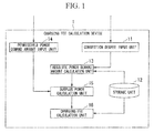
- Fig. 1 is a block diagram illustrating a configuration of the charging fee calculation device according to the first embodiment.
- the charging fee calculation device 1 of this embodiment illustrated in Fig. 1 is a device for outputting a charging fee so that power demand by EVs and a power supply amount from a power generation facility become a proper balance based on a congestion degree of vehicles assumed within a region and the power supply amount from the power generation facility.
- the charging fee calculation device 1 includes at least processing units of a congestion degree input unit 11, an absolute power demand amount calculation unit 13, a permissible power demand amount input unit 14, a surplus power calculation unit 15, and a charging fee calculation unit 16, and a storage unit 12.
- the congestion degree input unit 11 is a processing unit configured to input a pre-calculated congestion degree of vehicles of a specified time within a predetermined region.
- the congestion degree for example, is a value calculated according to the number of vehicles located within the predetermined region, and is a numeric value representing a degree of congestion of the vehicles within the predetermined region.
- the storage unit 12 stores various types of information to be used in calculation of a charging fee.
- the storage unit 12 stores congestion degree/absolute power demand amount relationship data.
- the congestion degree/absolute power demand amount relationship data represents a relationship between the congestion degree of the vehicles within the predetermined region and an absolute demand amount which is a sum of charge amounts necessary for vehicles located within the predetermined region to move outside of the predetermined region.
- the storage unit 12 stores power demand amount/charging fee relationship data representing the power demand amount and a charging fee per unit amount of power.
- the absolute power demand amount calculation unit 13 is the processing unit configured to calculate an absolute power demand amount at the specified time from the input congestion degree based on the congestion degree/absolute power demand amount relationship data.
- permissible power demand amount input unit 14 is the processing unit configured to input a permissible power demand amount in which supply by the power generation facility is possible at the specified time within the predetermined region.
- the surplus power calculation unit 15 is the processing unit configured to calculate a surplus power amount representing a difference between the input permissible power demand amount and the calculated absolute power demand amount.
- the charging fee calculation unit 16 is the processing unit configured to calculate the charging fee based on the power demand amount/charging fee relationship data and the calculated surplus power amount.
- the power generation facility in this embodiment generates power using renewable energy such as solar power generation or hydraulic power generation and supplies the power to the predetermined region.
- the power generation facility may further supply power generated by nuclear energy, thermal energy, or the like in addition to the renewable energy.
- the predetermined region may be a division region for every predetermined autonomous community such as a municipality or a prefecture or may be any other division region.
- Fig. 2 is a diagram illustrating the congestion degree/absolute power demand amount relationship data.
- the congestion degree/absolute power demand amount relationship data represents a relationship between a current or future congestion degree of vehicles within the predetermined region and an absolute power demand amount.
- the absolute power demand amount is a sum of charge amounts necessary for the vehicles located within the predetermined region to move to the outside of the predetermined region.
- the congestion degree/absolute power demand amount relationship data represents that the absolute power demand amount, which is the sum of charge amounts necessary for the vehicles to move to the outside of the predetermined region, is also increased when the congestion degree is increased.
- the congestion degree/absolute power demand amount relationship data of each predetermined region calculated by a simulator such as a congestion degree/absolute power demand amount relationship data generation device is recorded on the storage unit 12.
- the congestion degree/absolute power demand amount relationship data illustrated in FIG. 2 is calculated by the congestion degree/absolute power demand amount relationship data generation device performing a traffic flow simulation process or an EV power consumption/charging action simulation process. These simulation processes are performed using the remaining charge amount and position of the vehicle, a movement distance X from the position to the outside of the predetermined region, a traveling distance Y per unit power consumption amount of the vehicle, etc.
- the congestion degree/absolute power demand amount relationship data generation device calculates the absolute power amount representing a power amount necessary for the vehicle to move to the outside of the predetermined region according to "movement distance X to outside of predetermined region ⁇ traveling distance Y per unit power consumption amount of vehicle.” Also, a power amount necessary for the vehicle to move to the charging facility outside the predetermined region may be defined as the absolute power amount according to "movement distance Z up to charging facility closest to outside of predetermined region ⁇ traveling distance Y per unit power consumption amount of vehicle.” Then, the congestion degree/absolute power demand amount relationship data generation device calculates a sum of values when "absolute power amount - remaining charge amount of vehicle” > 0 calculated for vehicles within the predetermined region as the absolute power demand amount necessary for the vehicles within the predetermined region to move to the outside of the predetermined region. The congestion degree/absolute power demand amount relationship data generation device performs the simulation process on this absolute power demand amount according to the congestion degree and generates the congestion degree/absolute power demand amount relationship data.
- the charging fee calculation device 1 may be configured to have a function of the congestion degree/absolute power demand amount relationship data generation device.
- the charging fee calculation device 1 includes an absolute power amount calculation unit, and the absolute power amount calculation unit calculates the above-described absolute power amount.
- a congestion degree/absolute power demand amount relationship data generation unit generates the congestion degree/absolute power demand amount relationship data according to the simulation process.
- Fig. 3 is a diagram illustrating the power demand amount/charging fee relationship data.
- the power demand amount/charging fee relationship data represents a relationship between the power demand amount (surplus power demand amount) and a charging fee per unit amount of power.
- the relationship represents that the charging fee per unit amount of power is low when the power demand amount is large and the charging fee per unit amount of power is high when the power demand amount is small.
- the power demand amount/charging fee relationship data for example, is data calculated based on a previous record, a questionnaire survey, etc.
- the power demand amount/charging fee relationship data may be calculated by a simulator such as a power demand amount/charging fee relationship data generation device, and may be information input by the charging fee calculation device 1 and recorded on the storage unit 12.
- Fig. 4 is a diagram illustrating a processing outline of the charging fee calculation device.
- Fig. 5 is a diagram illustrating a processing flow of the charging fee calculation device.
- the congestion degree input unit 11 inputs a congestion degree at a specified time (step S101).
- the congestion degree for example, may be a value calculated by the simulator based on newly or previously obtained data according to a traffic volume survey, and may be represented by either of a ratio of a current traffic volume (the number of vehicles) to a saturated traffic volume and the number of vehicles of a current actual traffic volume. Alternatively, the congestion degree may be other information representing a degree of congestion.
- the congestion degree input unit 11 outputs the input congestion degree to the absolute power demand amount calculation unit 13.
- the absolute power demand amount calculation unit 13 reads the congestion degree/absolute power demand amount relationship data from the storage unit 12 (step S102). Then, the absolute power demand amount corresponding to the congestion degree input from the congestion degree input unit 11 is calculated based on the congestion degree/absolute power demand amount relationship data. Specifically, when the absolute power demand amount corresponding to a value of the congestion degree of each certain interval is held, the congestion degree/absolute power demand amount relationship data is calculated by interpolation calculation or the like. In addition, the absolute power demand amount calculation unit 13 outputs the calculated absolute power demand amount to the surplus power calculation unit 15.
- the permissible power demand amount input unit 14 inputs a permissible power demand amount at the specified time (step S103).
- the permissible power demand amount is information calculated by simulation of a weather forecast or the like. For example, a current or future permissible power demand amount is calculated by a power plant having a power generation station or a meteorological agency.
- the permissible power demand amount is distributed from a distribution server or the like configured to distribute its information and input by the permissible power demand amount input unit 14 via a communication network.
- a processing unit configured to calculate the future permissible power demand amount according to time based on various types of information such as acquired weather forecast data may be provided within the charging fee calculation device 1.
- the permissible power demand amount input unit 14 outputs the permissible power demand amount at the input specified time to the surplus power calculation unit 15.
- the surplus power calculation unit 15 calculates surplus power of the specified time within the predetermined region using the absolute power demand amount input from the absolute power demand amount calculation unit 13 and the permissible power demand amount input from the permissible power demand amount input unit 14 (step S104). Specifically, the surplus power is calculated by "permissible power demand amount - absolute power demand amount.” Then, the surplus power calculation unit 15 outputs the calculated surplus power to the charging fee calculation unit 16.
- the charging fee calculation unit 16 reads the power demand amount/charging fee relationship data from the storage unit 12 (step S105). Then, the charging fee calculation unit 16 calculates the charging fee in the case of the power demand amount corresponding to the surplus power input from the surplus power calculation unit 15 based on the power demand amount/charging fee relationship data (step S106).
- the charging fee of the case of the power amount corresponding to the surplus power amount according to the congestion degree within the predetermined region is set based on the relationship between the power demand and the charging fee according to the congestion degree calculated based on the simulation.
- Fig. 6 is a block diagram illustrating a configuration of the charging fee calculation device according to the second embodiment.
- the configuration of the charging fee calculation device 1 is obtained by adding the configuration of the charging fee output unit 17 to the configuration of the charging fee calculation device 1 illustrated in Fig. 1 .
- the charging fee output unit 17 outputs information of the charging fee calculated by the charging fee calculation unit 16 to the vehicle or the charging facility.
- the charging fee calculation device 1 is connected to the vehicle or the charging facility via a wireless or wired communication network or the like.
- the information of the charging fee output from the charging fee output unit 17 is input to the vehicle or the charging facility and displayed on a display unit provided in the vehicle or the charging facility.
- the charging fee calculation device 1 may be configured to calculate charging fees at a plurality of different future times and output (distribute) the calculated charging fees to the vehicle or the charging facility.
- the vehicle or charging facility displays the charging fees for the plurality of different future times on the display unit.
- the charging fee calculation device 1 may be configured to calculate charging fees of future time zones using charging fees for specified times included in the time zones and output the calculated charging fees to the vehicle or an induced electricity facility. For example, an average value of charging fees included in the future time zone is output as the charging fee of the time zone.
- the charging fee calculation device 1 may be configured to calculate charging fees for each of a plurality of regions and the charging fee output unit 17 may be configured to output the charging fees of the plurality of regions to the vehicle or the charging facility.
- the charging fee fluctuates according to the congestion degree of the vehicles in a predetermined region and the charging fee is calculated to be lower for a region of a lower congestion region. Accordingly, it is possible to smooth variation in the congestion degree by moving the vehicle from a predetermined region of a high congestion degree to a predetermined region of a low congestion degree. In addition, it is possible to manage the smoothing of the congestion degree for every predetermined region based on the charging fee.
- the charging fee calculation device 1 may be configured to output the charging fee to any device other than the vehicle or the charging facility.
- the charging fee may be configured to include a first charging fee to be applied when charging is performed up to a charge amount necessary to move to the outside of the predetermined region and a second charging fee to be applied when charging exceeding the charge amount is performed.
- the charging fee calculation device 1 may be configured to set the first charging fee to a pre-acquired value, set the second charging fee to a value calculated based on the power demand amount/charging fee relationship data and the surplus power amount, and distribute the first charging fee and the second charging fee to the vehicle or the charging facility.
- the first charging fee for example, is acquired via the communication network or read from the storage unit 12.
- an amount of payment money for power sale is calculated according to the first charging fee until it is determined that charging has been performed up to a charge amount necessary to move outside of a predetermined region by reading a charge power amount of a current vehicle, and an amount of payment money for power sale is calculated according to the second charging fee for more charging.
- the second charging fee is set to be higher than the first charging fee, management is possible so that an environment for causing a vehicle driver to actively charge the vehicle is formed until the charge amount accumulated in a storage battery within the vehicle reaches an absolute power amount (until the vehicle is charged by a charge amount necessary to move to the outside of the predetermined region).
- the second charging fee can be expected to decrease due to the demand of charging having reached the absolute power demand amount.
- the charging fee calculation device 1 may be configured to change the calculation of the charging fee and the cycle of the output. At this time, the calculation of the charging fee and the cycle of the output are appropriately set for the purpose of avoiding traffic disorder. For example, when a plurality of different charging fees are output during movement, the vehicle driver is considered to be moving between regions for the purpose of charging in a region in which charging is cheap due to a change in the charging fee, thus causing disorder in traffic. Accordingly, for example, a process of acquiring information about the presence/absence of movement from the vehicle, detecting the movement of the vehicle, and outputting one charging fee in one movement, or the like may be configured to be performed.
- the charging fee calculation device of the present invention has been described above, it is possible to manage smoothing of a congestion degree of vehicles for every predetermined region according to a charging fee according to the above-described process.
- the above-described charging fee calculation device internally includes a computer system.
- the steps of each of the above-described processes are stored in a program format on a computer-readable recording medium, and the above-described processes are executed by causing a computer to read and execute the program.
- the computer-readable recording medium refers to a magnetic disk, a magneto-optical disc, a compact disc-read only memory (CD-ROM), a digital versatile disc (DVD)-ROM, a semiconductor memory, or the like.
- the computer program may be configured to be distributed to a computer via a communication circuit and executed by the computer receiving the distribution.
- the above-described program may be a program for implementing some of the above-described functions.
- the above-described program may also be a program capable of implementing the above-described functions in combination with a program already recorded on the computer system, that is, a so-called differential file (differential program).
- the present invention is widely applicable to a charging fee calculation device, a charging fee calculation method, and its program for power with which a vehicle or the like is charged, and enables smoothing of a congestion degree of vehicles for every predetermined region to be managed according to a charging fee.
Landscapes
- Engineering & Computer Science (AREA)
- Business, Economics & Management (AREA)
- Power Engineering (AREA)
- Mechanical Engineering (AREA)
- Transportation (AREA)
- Strategic Management (AREA)
- Finance (AREA)
- Economics (AREA)
- Development Economics (AREA)
- Accounting & Taxation (AREA)
- General Physics & Mathematics (AREA)
- Health & Medical Sciences (AREA)
- Physics & Mathematics (AREA)
- General Business, Economics & Management (AREA)
- Entrepreneurship & Innovation (AREA)
- Theoretical Computer Science (AREA)
- Marketing (AREA)
- Human Resources & Organizations (AREA)
- General Health & Medical Sciences (AREA)
- Water Supply & Treatment (AREA)
- Data Mining & Analysis (AREA)
- Public Health (AREA)
- Primary Health Care (AREA)
- Tourism & Hospitality (AREA)
- Game Theory and Decision Science (AREA)
- Management, Administration, Business Operations System, And Electronic Commerce (AREA)
- Charge And Discharge Circuits For Batteries Or The Like (AREA)
- Supply And Distribution Of Alternating Current (AREA)
Abstract
Description
- The present invention relates to a charging fee calculation device, a charging fee calculation method, and its program for power with which a vehicle or the like is charged.
- Priority is claimed on Japanese Patent Application No.
2011-245685, filed November 9, 2011 - In recent years, the practical use of electric vehicles (hereinafter referred to as EVs), which use electricity as a power source, has been advanced and their penetration rate has increased. An EV has a battery to receive the supply of power from a charging facility called a charging station. Here, as the penetration rate of EVs increases, power demand for EVs in a charging facility within a region increases. In addition, the power demand for EVs varies with time due to a vehicle congestion degree of EVs, general vehicles, etc. within the region. Thus, in a power grid within a region, various systems for managing the supply-demand balance of power have been proposed in consideration of the fact that the load increases in a time zone in which the power demand for EVs increases.
- For example, a management device for preparing information defining an enjoyable reward for consumers according to charging action for EVs of the consumers or a constraint of the charging action, creating a charging plan to maximize the reward based on the information, and instructing a power facility to start charging according to the created charging plan has been proposed (for example, see Patent Literature 1). Here, for example, a charging fee itself is considered as the above-described reward. Electricity demand by consumers generally increases when the charging fee is low, and the electricity demand by the consumers decreases when the charging fee is high.
- [Patent Literature 1]
- Japanese Unexamined Patent Application, First Publication No.
2010-81722 - However, a charging fee setting method in which a proper power supply-demand balance can be maintained is not disclosed in
Patent Literature 1. Thus, when the charging fee is improperly set, power demand by EVs within the region may exceed power supply capability. - Therefore, an object of the present invention is to provide a charging fee calculation device, a charging fee calculation method, and its program capable of solving the above-described problem.
- In order to achieve the aforementioned object, the present invention is a charging fee calculation device including: a congestion degree input unit configured to input a pre-calculated congestion degree of vehicles within a predetermined region at a specified time; an absolute power demand amount calculation unit configured to calculate an absolute power demand amount at the specified time from the input congestion degree based on pre-calculated congestion degree/absolute power demand amount relationship data representing a relationship between the congestion degree of vehicles within the predetermined region and the absolute power demand amount which is a sum of charge amounts necessary for the vehicles to move outside of the predetermined region; a permissible power demand amount input unit configured to input a permissible power demand amount in which supply by a power generation facility is possible within the predetermined region at the specified time; a surplus power calculation unit configured to calculate a surplus power amount representing a difference between the permissible power demand amount and the absolute power demand amount; and a charging fee calculation unit configured to calculate a charging fee based on power demand amount/charging fee relationship data representing a relationship between a power demand amount and a charging fee per unit amount of power and the calculated surplus power amount.
- In addition, in the above-described charging fee calculation device of the present invention, the charging fee includes a first charging fee to be applied when charging is performed up to a charge amount necessary to move to the outside of the predetermined region and a second charging fee to be applied when charging exceeding the charge amount is performed, and the charging fee calculation unit sets the first charging fee to a pre-acquired value and sets the second charging fee to a value calculated based on the power demand amount/charging fee relationship data and the surplus power amount.
- In addition, the above-described charging fee calculation device of the present invention includes a charging fee output unit configured to output the first charging fee and the second charging fee.
- In addition, in the above-described charging fee calculation device of the present invention, the charging fee output unit distributes the first charging fee and the second charging fee using a communication network.
- In addition, the above-described charging fee calculation device of the present invention includes an absolute power amount calculation unit configured to calculate an absolute power amount representing a power amount necessary to move to the outside of the predetermined region based on a distance from a position of the vehicle to the outside of the predetermined region and a traveling distance of the vehicle per unit power consumption amount.
- In addition, the above-described charging fee calculation device of the present invention includes an absolute power amount calculation unit configured to calculate an absolute power amount representing a power amount necessary to move to the outside of the predetermined region based on a distance from a position of the vehicle to a charging facility closest to the outside of the predetermined region and a traveling distance of the vehicle per unit power consumption amount.
- In addition, the present invention is a charging fee calculation method for use in a charging fee calculation device, the charging fee calculation method including: inputting, by a congestion degree input unit, a pre-calculated congestion degree of vehicles within a predetermined region at a specified time; calculating, by an absolute power demand amount calculation unit, an absolute power demand amount at the specified time from the input congestion degree based on pre-calculated congestion degree/absolute power demand amount relationship data representing a relationship between the congestion degree of vehicles within the predetermined region and the absolute power demand amount which is a sum of charge amounts necessary for the vehicles to move outside of the predetermined region; inputting, by a permissible power demand amount input unit, a permissible power demand amount in which supply by a power generation facility is possible within the predetermined region at the specified time; calculating, by a surplus power calculation unit, a surplus power amount representing a difference between the permissible power demand amount and the absolute power demand amount; and calculating, by a charging fee calculation unit, a charging fee based on power demand amount/charging fee relationship data representing a relationship between a power demand amount and a charging fee per unit amount of power and the calculated surplus power amount.
- In addition, the present invention is a program for causing a computer of a charging fee calculation device to function as: a congestion degree input means configured to input a pre-calculated congestion degree of vehicles within a predetermined region at a specified time; an absolute power demand amount calculation means configured to calculate an absolute power demand amount at the specified time from the input congestion degree based on pre-calculated congestion degree/absolute power demand amount relationship data representing a relationship between the congestion degree of vehicles within the predetermined region and the absolute power demand amount which is a sum of charge amounts necessary for the vehicles to move outside of the predetermined region; a permissible power demand amount input means configured to input a permissible power demand amount in which supply by a power generation facility is possible within the predetermined region at the specified time; a surplus power calculation means configured to calculate a surplus power amount representing a difference between the permissible power demand amount and the absolute power demand amount; and a charging fee calculation means configured to calculate a charging fee based on power demand amount/charging fee relationship data representing a relationship between a power demand amount and a charging fee per unit amount of power and the calculated surplus power amount.
- According to the present invention, it is possible to manage smoothing of a congestion degree of vehicles for each predetermined region according to a charging fee.
-
-
Fig. 1 is a block diagram illustrating a configuration of a charging fee calculation device according to a first embodiment. -
Fig. 2 is a diagram illustrating congestion degree/absolute power demand amount relationship data. -
Fig. 3 is a diagram illustrating power demand amount/charging fee relationship data. -
Fig. 4 is a diagram illustrating a processing outline of the charging fee calculation device. -
Fig. 5 is a diagram illustrating a processing flow of the charging fee calculation device. -
Fig. 6 is a block diagram illustrating a configuration of the charging fee calculation device according to a second embodiment. - Hereinafter, a charging fee calculation device according to the first embodiment of the present invention will be described with reference to the drawings.
-
Fig. 1 is a block diagram illustrating a configuration of the charging fee calculation device according to the first embodiment. - The charging
fee calculation device 1 of this embodiment illustrated inFig. 1 is a device for outputting a charging fee so that power demand by EVs and a power supply amount from a power generation facility become a proper balance based on a congestion degree of vehicles assumed within a region and the power supply amount from the power generation facility. - The charging
fee calculation device 1 includes at least processing units of a congestiondegree input unit 11, an absolute power demandamount calculation unit 13, a permissible power demandamount input unit 14, a surpluspower calculation unit 15, and a chargingfee calculation unit 16, and astorage unit 12. - Here, the congestion
degree input unit 11 is a processing unit configured to input a pre-calculated congestion degree of vehicles of a specified time within a predetermined region. The congestion degree, for example, is a value calculated according to the number of vehicles located within the predetermined region, and is a numeric value representing a degree of congestion of the vehicles within the predetermined region. - In addition, the
storage unit 12 stores various types of information to be used in calculation of a charging fee. For example, thestorage unit 12 stores congestion degree/absolute power demand amount relationship data. The congestion degree/absolute power demand amount relationship data represents a relationship between the congestion degree of the vehicles within the predetermined region and an absolute demand amount which is a sum of charge amounts necessary for vehicles located within the predetermined region to move outside of the predetermined region. - In addition, for example, the
storage unit 12 stores power demand amount/charging fee relationship data representing the power demand amount and a charging fee per unit amount of power. - In addition, the absolute power demand
amount calculation unit 13 is the processing unit configured to calculate an absolute power demand amount at the specified time from the input congestion degree based on the congestion degree/absolute power demand amount relationship data. - In addition, the permissible power demand
amount input unit 14 is the processing unit configured to input a permissible power demand amount in which supply by the power generation facility is possible at the specified time within the predetermined region. - In addition, the surplus
power calculation unit 15 is the processing unit configured to calculate a surplus power amount representing a difference between the input permissible power demand amount and the calculated absolute power demand amount. - In addition, the charging
fee calculation unit 16 is the processing unit configured to calculate the charging fee based on the power demand amount/charging fee relationship data and the calculated surplus power amount. - The power generation facility in this embodiment generates power using renewable energy such as solar power generation or hydraulic power generation and supplies the power to the predetermined region. However, the power generation facility may further supply power generated by nuclear energy, thermal energy, or the like in addition to the renewable energy. In addition, the predetermined region may be a division region for every predetermined autonomous community such as a municipality or a prefecture or may be any other division region.
- Next, data to be stored by the storage unit will be described.
-
Fig. 2 is a diagram illustrating the congestion degree/absolute power demand amount relationship data. - As illustrated in this drawing, the congestion degree/absolute power demand amount relationship data represents a relationship between a current or future congestion degree of vehicles within the predetermined region and an absolute power demand amount. The absolute power demand amount is a sum of charge amounts necessary for the vehicles located within the predetermined region to move to the outside of the predetermined region. When the congestion degree within the predetermined region increases, the charge amount necessary for one vehicle to move to the outside of the predetermined region increases according to a decrease in an average speed or an increase in speed irregularity due to congestion. Accordingly, the congestion degree/absolute power demand amount relationship data represents that the absolute power demand amount, which is the sum of charge amounts necessary for the vehicles to move to the outside of the predetermined region, is also increased when the congestion degree is increased.
- The congestion degree/absolute power demand amount relationship data of each predetermined region calculated by a simulator such as a congestion degree/absolute power demand amount relationship data generation device is recorded on the
storage unit 12. - Here, the congestion degree/absolute power demand amount relationship data illustrated in
FIG. 2 is calculated by the congestion degree/absolute power demand amount relationship data generation device performing a traffic flow simulation process or an EV power consumption/charging action simulation process. These simulation processes are performed using the remaining charge amount and position of the vehicle, a movement distance X from the position to the outside of the predetermined region, a traveling distance Y per unit power consumption amount of the vehicle, etc. More specifically, the congestion degree/absolute power demand amount relationship data generation device calculates the absolute power amount representing a power amount necessary for the vehicle to move to the outside of the predetermined region according to "movement distance X to outside of predetermined region ÷ traveling distance Y per unit power consumption amount of vehicle." Also, a power amount necessary for the vehicle to move to the charging facility outside the predetermined region may be defined as the absolute power amount according to "movement distance Z up to charging facility closest to outside of predetermined region ÷ traveling distance Y per unit power consumption amount of vehicle." Then, the congestion degree/absolute power demand amount relationship data generation device calculates a sum of values when "absolute power amount - remaining charge amount of vehicle" > 0 calculated for vehicles within the predetermined region as the absolute power demand amount necessary for the vehicles within the predetermined region to move to the outside of the predetermined region. The congestion degree/absolute power demand amount relationship data generation device performs the simulation process on this absolute power demand amount according to the congestion degree and generates the congestion degree/absolute power demand amount relationship data. - The charging
fee calculation device 1 may be configured to have a function of the congestion degree/absolute power demand amount relationship data generation device. In this case, the chargingfee calculation device 1 includes an absolute power amount calculation unit, and the absolute power amount calculation unit calculates the above-described absolute power amount. In addition, a congestion degree/absolute power demand amount relationship data generation unit generates the congestion degree/absolute power demand amount relationship data according to the simulation process. -
Fig. 3 is a diagram illustrating the power demand amount/charging fee relationship data. - As illustrated in this drawing, the power demand amount/charging fee relationship data represents a relationship between the power demand amount (surplus power demand amount) and a charging fee per unit amount of power. The relationship represents that the charging fee per unit amount of power is low when the power demand amount is large and the charging fee per unit amount of power is high when the power demand amount is small. The power demand amount/charging fee relationship data, for example, is data calculated based on a previous record, a questionnaire survey, etc. The power demand amount/charging fee relationship data may be calculated by a simulator such as a power demand amount/charging fee relationship data generation device, and may be information input by the charging
fee calculation device 1 and recorded on thestorage unit 12. -
Fig. 4 is a diagram illustrating a processing outline of the charging fee calculation device. -
Fig. 5 is a diagram illustrating a processing flow of the charging fee calculation device. - Next, the processing flow of the charging fee calculation device will be described in order.
- In the charging
fee calculation device 1, first, the congestiondegree input unit 11 inputs a congestion degree at a specified time (step S101). The congestion degree, for example, may be a value calculated by the simulator based on newly or previously obtained data according to a traffic volume survey, and may be represented by either of a ratio of a current traffic volume (the number of vehicles) to a saturated traffic volume and the number of vehicles of a current actual traffic volume. Alternatively, the congestion degree may be other information representing a degree of congestion. When the congestion degree is input at the specified time, the congestiondegree input unit 11 outputs the input congestion degree to the absolute power demandamount calculation unit 13. - Next, the absolute power demand
amount calculation unit 13 reads the congestion degree/absolute power demand amount relationship data from the storage unit 12 (step S102). Then, the absolute power demand amount corresponding to the congestion degree input from the congestiondegree input unit 11 is calculated based on the congestion degree/absolute power demand amount relationship data. Specifically, when the absolute power demand amount corresponding to a value of the congestion degree of each certain interval is held, the congestion degree/absolute power demand amount relationship data is calculated by interpolation calculation or the like. In addition, the absolute power demandamount calculation unit 13 outputs the calculated absolute power demand amount to the surpluspower calculation unit 15. - On the other hand, the permissible power demand
amount input unit 14 inputs a permissible power demand amount at the specified time (step S103). The permissible power demand amount is information calculated by simulation of a weather forecast or the like. For example, a current or future permissible power demand amount is calculated by a power plant having a power generation station or a meteorological agency. The permissible power demand amount is distributed from a distribution server or the like configured to distribute its information and input by the permissible power demandamount input unit 14 via a communication network. Alternatively, a processing unit configured to calculate the future permissible power demand amount according to time based on various types of information such as acquired weather forecast data may be provided within the chargingfee calculation device 1. The permissible power demandamount input unit 14 outputs the permissible power demand amount at the input specified time to the surpluspower calculation unit 15. - Next, the surplus
power calculation unit 15 calculates surplus power of the specified time within the predetermined region using the absolute power demand amount input from the absolute power demandamount calculation unit 13 and the permissible power demand amount input from the permissible power demand amount input unit 14 (step S104). Specifically, the surplus power is calculated by "permissible power demand amount - absolute power demand amount." Then, the surpluspower calculation unit 15 outputs the calculated surplus power to the chargingfee calculation unit 16. - Next, the charging
fee calculation unit 16 reads the power demand amount/charging fee relationship data from the storage unit 12 (step S105). Then, the chargingfee calculation unit 16 calculates the charging fee in the case of the power demand amount corresponding to the surplus power input from the surpluspower calculation unit 15 based on the power demand amount/charging fee relationship data (step S106). - According to the above process, the charging fee of the case of the power amount corresponding to the surplus power amount according to the congestion degree within the predetermined region is set based on the relationship between the power demand and the charging fee according to the congestion degree calculated based on the simulation. Thereby, it is possible to adjust the power demand using the charging fee, and for example, it is possible to prevent excessive demand due to a significantly low charging fee.
-
Fig. 6 is a block diagram illustrating a configuration of the charging fee calculation device according to the second embodiment. - In the drawing, the configuration of the charging
fee calculation device 1 is obtained by adding the configuration of the chargingfee output unit 17 to the configuration of the chargingfee calculation device 1 illustrated inFig. 1 . - In the charging fee calculation device I according to the second embodiment, the charging
fee output unit 17 outputs information of the charging fee calculated by the chargingfee calculation unit 16 to the vehicle or the charging facility. For example, the chargingfee calculation device 1 is connected to the vehicle or the charging facility via a wireless or wired communication network or the like. - Then, the information of the charging fee output from the charging
fee output unit 17 is input to the vehicle or the charging facility and displayed on a display unit provided in the vehicle or the charging facility. - Here, the charging
fee calculation device 1 may be configured to calculate charging fees at a plurality of different future times and output (distribute) the calculated charging fees to the vehicle or the charging facility. In this case, the vehicle or charging facility displays the charging fees for the plurality of different future times on the display unit. When the charging fees for the plurality of future times have been calculated as described above, a frequency at which the vehicle is used is considered to be increased in a time zone in which the charging fee is low as shown in a list of charging fees. Thereby, it is possible to manage the reduction of variation of a congestion degree according to time based on the charging fee. - Alternatively, the charging
fee calculation device 1 may be configured to calculate charging fees of future time zones using charging fees for specified times included in the time zones and output the calculated charging fees to the vehicle or an induced electricity facility. For example, an average value of charging fees included in the future time zone is output as the charging fee of the time zone. - In addition, the charging
fee calculation device 1 may be configured to calculate charging fees for each of a plurality of regions and the chargingfee output unit 17 may be configured to output the charging fees of the plurality of regions to the vehicle or the charging facility. According to this process, the charging fee fluctuates according to the congestion degree of the vehicles in a predetermined region and the charging fee is calculated to be lower for a region of a lower congestion region. Accordingly, it is possible to smooth variation in the congestion degree by moving the vehicle from a predetermined region of a high congestion degree to a predetermined region of a low congestion degree. In addition, it is possible to manage the smoothing of the congestion degree for every predetermined region based on the charging fee. - Also, the charging
fee calculation device 1 may be configured to output the charging fee to any device other than the vehicle or the charging facility. - The charging fee may be configured to include a first charging fee to be applied when charging is performed up to a charge amount necessary to move to the outside of the predetermined region and a second charging fee to be applied when charging exceeding the charge amount is performed. At this time, the charging
fee calculation device 1 may be configured to set the first charging fee to a pre-acquired value, set the second charging fee to a value calculated based on the power demand amount/charging fee relationship data and the surplus power amount, and distribute the first charging fee and the second charging fee to the vehicle or the charging facility. Also, the first charging fee, for example, is acquired via the communication network or read from thestorage unit 12. - According to this process, for example, in the charging facility, an amount of payment money for power sale is calculated according to the first charging fee until it is determined that charging has been performed up to a charge amount necessary to move outside of a predetermined region by reading a charge power amount of a current vehicle, and an amount of payment money for power sale is calculated according to the second charging fee for more charging. If the second charging fee is set to be higher than the first charging fee, management is possible so that an environment for causing a vehicle driver to actively charge the vehicle is formed until the charge amount accumulated in a storage battery within the vehicle reaches an absolute power amount (until the vehicle is charged by a charge amount necessary to move to the outside of the predetermined region). Thereby, the second charging fee can be expected to decrease due to the demand of charging having reached the absolute power demand amount.
- The charging
fee calculation device 1 may be configured to change the calculation of the charging fee and the cycle of the output. At this time, the calculation of the charging fee and the cycle of the output are appropriately set for the purpose of avoiding traffic disorder. For example, when a plurality of different charging fees are output during movement, the vehicle driver is considered to be moving between regions for the purpose of charging in a region in which charging is cheap due to a change in the charging fee, thus causing disorder in traffic. Accordingly, for example, a process of acquiring information about the presence/absence of movement from the vehicle, detecting the movement of the vehicle, and outputting one charging fee in one movement, or the like may be configured to be performed. - Although the charging fee calculation device of the present invention has been described above, it is possible to manage smoothing of a congestion degree of vehicles for every predetermined region according to a charging fee according to the above-described process.
- The above-described charging fee calculation device internally includes a computer system. The steps of each of the above-described processes are stored in a program format on a computer-readable recording medium, and the above-described processes are executed by causing a computer to read and execute the program. Here, the computer-readable recording medium refers to a magnetic disk, a magneto-optical disc, a compact disc-read only memory (CD-ROM), a digital versatile disc (DVD)-ROM, a semiconductor memory, or the like. The computer program may be configured to be distributed to a computer via a communication circuit and executed by the computer receiving the distribution.
- In addition, the above-described program may be a program for implementing some of the above-described functions.
- The above-described program may also be a program capable of implementing the above-described functions in combination with a program already recorded on the computer system, that is, a so-called differential file (differential program).
- The present invention is widely applicable to a charging fee calculation device, a charging fee calculation method, and its program for power with which a vehicle or the like is charged, and enables smoothing of a congestion degree of vehicles for every predetermined region to be managed according to a charging fee.
-
- 1
- Charging fee calculation device
- 11
- Congestion degree input unit
- 12
- Storage unit
- 13
- Absolute power demand amount calculation unit
- 14
- Permissible power demand amount input unit
- 15
- Surplus power calculation unit
- 16
- Charging fee calculation unit
- 17
- Charging fee output unit
Claims (8)
- A charging fee calculation device comprising:a congestion degree input unit configured to input a pre-calculated congestion degree of vehicles within a predetermined region at a specified time;an absolute power demand amount calculation unit configured to calculate an absolute power demand amount at the specified time from the input congestion degree based on pre-calculated congestion degree/absolute power demand amount relationship data representing a relationship between the congestion degree of vehicles within the predetermined region and the absolute power demand amount which is a sum of charge amounts necessary for the vehicles to move outside of the predetermined region;a permissible power demand amount input unit configured to input a permissible power demand amount in which supply by a power generation facility is possible within the predetermined region at the specified time;a surplus power calculation unit configured to calculate a surplus power amount representing a difference between the permissible power demand amount and the absolute power demand amount; anda charging fee calculation unit configured to calculate a charging fee based on power demand amount/charging fee relationship data representing a relationship between a power demand amount and a charging fee per unit amount of power and the calculated surplus power amount.
- The charging fee calculation device according to claim 1,
wherein the charging fee includes a first charging fee to be applied when charging is performed up to a charge amount necessary to move to the outside of the predetermined region and a second charging fee to be applied when charging exceeding the charge amount is performed, and
wherein the charging fee calculation unit sets the first charging fee to a pre-acquired value and sets the second charging fee to a value calculated based on the power demand amount/charging fee relationship data and the surplus power amount. - The charging fee calculation device according to claim 2, comprising:a charging fee output unit configured to output the first charging fee and the second charging fee.
- The charging fee calculation device according to claim 3, wherein the charging fee output unit distributes the first charging fee and the second charging fee using a communication network.
- The charging fee calculation device according to any one of claims 1 to 4, comprising:an absolute power amount calculation unit configured to calculate an absolute power amount representing a power amount necessary to move to the outside of the predetermined region based on a distance from a position of the vehicle to the outside of the predetermined region and a traveling distance of the vehicle per unit power consumption amount.
- The charging fee calculation device according to any one of claims 1 to 4, comprising:an absolute power amount calculation unit configured to calculate an absolute power amount representing a power amount necessary to move to the outside of the predetermined region based on a distance from a position of the vehicle to a charging facility closest to the outside of the predetermined region and a traveling distance of the vehicle per unit power consumption amount.
- A charging fee calculation method for use in a charging fee calculation device, the charging fee calculation method comprising:inputting, by a congestion degree input unit, a pre-calculated congestion degree of vehicles within a predetermined region at a specified time;calculating, by an absolute power demand amount calculation unit, an absolute power demand amount at the specified time from the input congestion degree based on pre-calculated congestion degree/absolute power demand amount relationship data representing a relationship between the congestion degree of vehicles within the predetermined region and the absolute power demand amount which is a sum of charge amounts necessary for the vehicles to move outside of the predetermined region;inputting, by a permissible power demand amount input unit, a permissible power demand amount in which supply by a power generation facility is possible within the predetermined region at the specified time;calculating, by a surplus power calculation unit, a surplus power amount representing a difference between the permissible power demand amount and the absolute power demand amount; andcalculating, by a charging fee calculation unit, a charging fee based on power demand amount/charging fee relationship data representing a relationship between a power demand amount and a charging fee per unit amount of power and the calculated surplus power amount.
- A program for causing a computer of a charging fee calculation device to function as:a congestion degree input means configured to input a pre-calculated congestion degree of vehicles within a predetermined region at a specified time;an absolute power demand amount calculation means configured to calculate an absolute power demand amount at the specified time from the input congestion degree based on pre-calculated congestion degree/absolute power demand amount relationship data representing a relationship between the congestion degree of vehicles within the predetermined region and the absolute power demand amount which is a sum of charge amounts necessary for the vehicles to move outside of the predetermined region;a permissible power demand amount input means configured to input a permissible power demand amount in which supply by a power generation facility is possible within the predetermined region at the specified time;a surplus power calculation means configured to calculate a surplus power amount representing a difference between the permissible power demand amount and the absolute power demand amount; anda charging fee calculation means configured to calculate a charging fee based on power demand amount/charging fee relationship data representing a relationship between a power demand amount and a charging fee per unit amount of power and the calculated surplus power amount.
Applications Claiming Priority (2)
| Application Number | Priority Date | Filing Date | Title |
|---|---|---|---|
| JP2011245685A JP5693432B2 (en) | 2011-11-09 | 2011-11-09 | Charging charge calculation device, charging charge calculation method, and program thereof |
| PCT/JP2012/078142 WO2013069518A1 (en) | 2011-11-09 | 2012-10-31 | Charging fee calculation device, charging fee calculation method, and program therefor |
Publications (2)
| Publication Number | Publication Date |
|---|---|
| EP2779084A1 true EP2779084A1 (en) | 2014-09-17 |
| EP2779084A4 EP2779084A4 (en) | 2015-07-08 |
Family
ID=48289895
Family Applications (1)
| Application Number | Title | Priority Date | Filing Date |
|---|---|---|---|
| EP12847800.5A Ceased EP2779084A4 (en) | 2011-11-09 | 2012-10-31 | Charging fee calculation device, charging fee calculation method, and program therefor |
Country Status (4)
| Country | Link |
|---|---|
| EP (1) | EP2779084A4 (en) |
| JP (1) | JP5693432B2 (en) |
| SG (1) | SG11201402170WA (en) |
| WO (1) | WO2013069518A1 (en) |
Families Citing this family (5)
| Publication number | Priority date | Publication date | Assignee | Title |
|---|---|---|---|---|
| KR101493246B1 (en) * | 2013-10-10 | 2015-02-17 | 한국에너지기술연구원 | Charge/discharge control apparatus and method |
| JP2019145088A (en) * | 2017-12-29 | 2019-08-29 | ゴゴロ インク | System and method for dynamically allocating energy between interchangeable energy storage stations |
| KR102517454B1 (en) * | 2019-12-20 | 2023-04-04 | 한국전자통신연구원 | Dynamic charging demand response method, dynamic charging demand control method based on consumer order and, demand management control system |
| KR102618817B1 (en) * | 2020-09-22 | 2023-12-27 | 세메스 주식회사 | Method for controlling transport vehicle in article transport system in fabrication facility and vehicle control apparatus thereof |
| JP2023170170A (en) * | 2022-05-18 | 2023-12-01 | 新電元工業株式会社 | Charging device, charging system and program |
Family Cites Families (3)
| Publication number | Priority date | Publication date | Assignee | Title |
|---|---|---|---|---|
| JP4909666B2 (en) * | 2006-07-24 | 2012-04-04 | 株式会社東芝 | Feeding system |
| JP4713623B2 (en) | 2008-09-25 | 2011-06-29 | 株式会社日立製作所 | Charge / discharge management device |
| JP5077701B2 (en) * | 2008-10-31 | 2012-11-21 | 本田技研工業株式会社 | Power supply control device |
-
2011
- 2011-11-09 JP JP2011245685A patent/JP5693432B2/en active Active
-
2012
- 2012-10-31 WO PCT/JP2012/078142 patent/WO2013069518A1/en not_active Ceased
- 2012-10-31 SG SG11201402170WA patent/SG11201402170WA/en unknown
- 2012-10-31 EP EP12847800.5A patent/EP2779084A4/en not_active Ceased
Also Published As
| Publication number | Publication date |
|---|---|
| JP5693432B2 (en) | 2015-04-01 |
| SG11201402170WA (en) | 2014-10-30 |
| EP2779084A4 (en) | 2015-07-08 |
| JP2013101554A (en) | 2013-05-23 |
| WO2013069518A1 (en) | 2013-05-16 |
Similar Documents
| Publication | Publication Date | Title |
|---|---|---|
| Sarker et al. | Optimal operation of aggregated electric vehicle charging stations coupled with energy storage | |
| Rahmani-Andebili et al. | Planning and operation of parking lots considering system, traffic, and drivers behavioral model | |
| Flath et al. | Improving electric vehicle charging coordination through area pricing | |
| Moeini-Aghtaie et al. | Optimized probabilistic PHEVs demand management in the context of energy hubs | |
| Wang et al. | Impact of plug-in hybrid electric vehicles on power systems with demand response and wind power | |
| Xi et al. | Using price-based signals to control plug-in electric vehicle fleet charging | |
| Bustos et al. | Energy storage and transmission expansion planning: substitutes or complements? | |
| Rolink et al. | Large-scale modeling of grid-connected electric vehicles | |
| Lyon et al. | Is “smart charging” policy for electric vehicles worthwhile? | |
| JP2015510199A5 (en) | ||
| EP4251464B1 (en) | Method and system for adaptively charging of electric vehicles | |
| Saklani et al. | Navigating the challenges of EV integration and demand-side management for India’s sustainable EV growth | |
| US20260004368A1 (en) | Method for optimizing the electrical network load by targeted charging of electric vehicles | |
| Chandrashekar et al. | Wind-integration benefits of controlled plug-in electric vehicle charging | |
| Le Floch et al. | Optimal charging of vehicle-to-grid fleets via PDE aggregation techniques | |
| CN110276557A (en) | A kind of inter-network grid dispatching work order creation method | |
| JP5693432B2 (en) | Charging charge calculation device, charging charge calculation method, and program thereof | |
| Retiere et al. | Fractal Grid–towards the future smart grid | |
| Gupta et al. | Value assessment method for expansion planning of generators and transmission networks: a non-iterative approach | |
| Mohammadian et al. | Spatial arbitrage through bidirectional electric vehicle charging with delivery fleets | |
| Mudgal et al. | Residential parking lot pricing strategy considering scheduling of electric vehicles | |
| Alguhi et al. | Optimizing EVs penetration levels in smart grids using dynamic pricing and renewable energy backed by BESS while maintaining grid constraints | |
| CN118633100A (en) | Disaster countermeasure plan formulation system and disaster countermeasure plan formulation method | |
| Rahmani-Andebili et al. | Traffic and grid-based parking lot allocation for PEVs considering driver behavioral model | |
| EP3437032B1 (en) | A system and method for adaptively maximizing cost savings or profits for utility usage |
Legal Events
| Date | Code | Title | Description |
|---|---|---|---|
| PUAI | Public reference made under article 153(3) epc to a published international application that has entered the european phase |
Free format text: ORIGINAL CODE: 0009012 |
|
| 17P | Request for examination filed |
Effective date: 20140507 |
|
| AK | Designated contracting states |
Kind code of ref document: A1 Designated state(s): AL AT BE BG CH CY CZ DE DK EE ES FI FR GB GR HR HU IE IS IT LI LT LU LV MC MK MT NL NO PL PT RO RS SE SI SK SM TR |
|
| DAX | Request for extension of the european patent (deleted) | ||
| RA4 | Supplementary search report drawn up and despatched (corrected) |
Effective date: 20150610 |
|
| RIC1 | Information provided on ipc code assigned before grant |
Ipc: G06Q 30/02 20120101AFI20150604BHEP Ipc: G06Q 50/06 20120101ALI20150604BHEP |
|
| 17Q | First examination report despatched |
Effective date: 20181120 |
|
| REG | Reference to a national code |
Ref country code: DE Ref legal event code: R003 |
|
| STAA | Information on the status of an ep patent application or granted ep patent |
Free format text: STATUS: THE APPLICATION HAS BEEN REFUSED |
|
| 18R | Application refused |
Effective date: 20191018 |