EP2778845A2 - Systems and methods for haptics in vibrating environments and devices - Google Patents
Systems and methods for haptics in vibrating environments and devices Download PDFInfo
- Publication number
- EP2778845A2 EP2778845A2 EP14158123.1A EP14158123A EP2778845A2 EP 2778845 A2 EP2778845 A2 EP 2778845A2 EP 14158123 A EP14158123 A EP 14158123A EP 2778845 A2 EP2778845 A2 EP 2778845A2
- Authority
- EP
- European Patent Office
- Prior art keywords
- haptic
- vibration
- parasitic
- effect
- haptic effect
- Prior art date
- Legal status (The legal status is an assumption and is not a legal conclusion. Google has not performed a legal analysis and makes no representation as to the accuracy of the status listed.)
- Withdrawn
Links
Images


Classifications
-
- G—PHYSICS
- G06—COMPUTING; CALCULATING OR COUNTING
- G06F—ELECTRIC DIGITAL DATA PROCESSING
- G06F3/00—Input arrangements for transferring data to be processed into a form capable of being handled by the computer; Output arrangements for transferring data from processing unit to output unit, e.g. interface arrangements
- G06F3/01—Input arrangements or combined input and output arrangements for interaction between user and computer
- G06F3/016—Input arrangements with force or tactile feedback as computer generated output to the user
-
- G—PHYSICS
- G08—SIGNALLING
- G08B—SIGNALLING OR CALLING SYSTEMS; ORDER TELEGRAPHS; ALARM SYSTEMS
- G08B6/00—Tactile signalling systems, e.g. personal calling systems
Definitions
- the present invention generally relates to haptic feedback, and more particularly to systems and methods for haptic feedback in vibrating environments and devices.
- Haptic feedback can provide a conduit for electronic devices to communicate information to users. This conduit can be in addition to standard visual or auditory effects.
- the number of devices that include some form of haptic feedback has increased dramatically over the past several years. However, some of these devices already output vibrations, for example, as a byproduct of their regular operation. Further, many devices may be used in a vibrating environment. Either of these may dull or overwhelm haptic effects. Accordingly, there is a need for a device to compensate for these background vibrations.
- Embodiments of the present disclosure include devices featuring haptics in vibrating environments and devices.
- a system according to the present disclosure may comprise: a haptic output device; a processor coupled to the haptic output device, the processor configured to: determine that a haptic effect should be generated; receive a signal associated with a parasitic vibration; determine a haptic effect based in part on the parasitic vibration; and output a haptic signal associated with the haptic effect to the haptic output device.
- One illustrative embodiment of the present disclosure comprises a device that may be used in an environment prone to vibration, for example, a smartphone or other device comprising a haptic output device and a user interface through which the user feels haptic effects.
- a mobile device of the illustrative embodiment may be used in for example, a car, an airplane, a bus, a train, or some other environment that has substantial vibrations. These parasitic vibrations may interfere with the haptic effects output by the illustrative mobile device. For example, a parasitic vibration may mask a vibration output by the haptic output device.
- the illustrative embodiment of the present disclosure comprises systems for compensating for these parasitic vibrations.
- the illustrative embodiment may comprise a data store comprising data associated with the parasitic vibrations. This data store may be local to the mobile device, or accessible via a network connection.
- the illustrative mobile device may receive a signal from the data store. Based on this signal, the illustrative mobile device may determine a haptic effect that is distinguishable from the parasitic vibration.
- This distinguishable haptic effect may comprise one or more of many potential haptic effects.
- the haptic effect may comprise a vibration based effect configured to be felt in spite of the parasitic vibration, e.g. a haptic effect at a different frequency and/or amplitude than the vibration and thus distinguishable from the parasitic vibration.
- the haptic effect may comprise an effect configured to compensate for the parasitic vibrations.
- the haptic effect may comprise a vibration at a frequency and amplitude configured to compensate for, or mask (e.g. "reduce” or "cancel") the parasitic vibration.
- the haptic effect may comprise a skin stretching effect, an electrostatic based effect, or a surface deformation effect.
- the parasitic vibration may have little or no impact on the haptic effect.
- the haptic effect may comprise a non-vibration based effect.
- the haptic effect may comprise an effect configured to control the parasitic vibration.
- the parasitic vibration may be the result of the normal operation of the device.
- the device may for example comprise a motor or other component that outputs the parasitic vibration.
- the haptic effect may comprise controlling the motor or other component to vary the parasitic vibration, and thus output a perceptible haptic effect.
- the mobile or other device may output a haptic effect that the user can perceive despite the parasitic vibration. This may enable the user to use the illustrative device in a vibrating environment, e.g. in a car, train, or airplane.
- the device may be incorporated into the vibrating environment.
- the illustrative device may comprise a touch screen display for use in a car stereo or a touch screen for use in an airplane entertainment system.
- the device may output a haptic effect that is distinguishable from the vibration of the larger system (e.g. the vibration as the car moves over the road or as the airplane experiences turbulence).
- the device may be a device that already includes a vibration, e.g. an electric razor, a kitchen appliance, or piece of industrial equipment.
- the parasitic vibration may be generated by a motor or other component on the device which normally serves a purpose other than for generating haptic effects.
- the haptic effect may be associated with controlling this motor or the like, e.g. briefly stopping or slowing its operation, and thus generating a perceptible haptic effect by stopping or slowing the parasitic vibration.
- Figure 1 is a block diagram of a system for haptics in vibrating environments and devices according to one embodiment of the disclosure.
- the system 100 shown in Figure 1 comprises a device 102.
- Device 102 may comprise one of a variety of handheld devices, such as a mobile phone, a personal digital assistant (PDA), or a handheld navigation system.
- PDA personal digital assistant
- the present disclosure may be implemented in a device that is not portable, for example, in an automobile console, an airplane console, a console for industrial equipment, a household appliance, a gaming console, or other device, whether primarily electronic or not.
- Embodiments of the present disclosure can be implemented in combination with, or may comprise combinations of: digital electronic circuitry, computer hardware, firmware, and software.
- the device 102 shown in Figure 1 comprises a processor 110.
- the processor 110 receives input signals and generates signals for communication, display, and providing haptic feedback.
- the processor 110 includes or is in communication with one or more computer-readable media, such as memory 112, which may comprise random access memory (RAM).
- RAM random access memory
- the processor 110 executes computer-executable program instructions stored in memory 112, such as executing one or more computer programs for messaging or for generating haptic feedback.
- Processor 110 may comprise a microprocessor, a digital signal processor (DSP), an application-specific integrated circuit (ASIC), one or more field programmable gate arrays (FPGAs), or state machines.
- the processor may further comprise a programmable electronic device such as a PLC, a programmable interrupt controller (PIC), a programmable logic device (PLD), a programmable read-only memory (PROM), an electronically programmable read-only memory (EPROM or EEPROM), or other similar devices.
- Memory 112 comprises a computer-readable medium that may store instructions, which, when executed by the processor 110, cause it to perform various steps, such as those described herein.
- Suitable computer-readable media may comprise, but are not limited to, non-transient computer readable media such as, an electronic, optical, magnetic, or other storage or transmission device capable of providing the processor 110 with computer-readable instructions.
- Other examples of media comprise, but are not limited to, a floppy disk, CD-ROM, magnetic disk, memory chip, ROM, RAM, ASIC, configured processor, all optical media, all magnetic tape or other magnetic media, or any other medium from which a computer processor can read.
- various other devices may include or comprise or constitute suitable computer-readable media, such as a router, private or public network, or other transmission device.
- the memory 112 may be internal to or external of the device 102.
- the processor 110, and the processing, described may be in one or more structures, and may be dispersed throughout one or more structures.
- Memory 112 may further comprise a data store comprising data associated with the parasitic vibrations.
- memory 112 may comprise a database of parasitic vibrations associated with various environments, which is accessible by processor 110.
- memory 112 may comprise a database of one or more templates of parasitic vibrations. These templates may comprise data associated with parasitic vibrations in common environments.
- the templates may comprise data associated with vibrations: on an airplane (e.g. in various levels of turbulence), a bus on various types of roads, a car on various types of roads, or another environment associated with background vibrations.
- the device 102 also comprises a user input device 114 in communication with the processor 110.
- the user input device 114 may comprise a touchscreen.
- User input device 114 may sense user interaction as well as the location of the interaction.
- the user input device may comprise a capacitance-based touchscreen.
- user input device 114 may comprise a button, switch, slider, or trackball.
- the device 102 may comprise both a touch screen and an additional user input device 114, or a non-touch sensitive screen and a user input device.
- the device 102 also comprises a display 116.
- Display 116 is in communication with processor 110 and is configured to display output from the processor 110 to the user.
- the device 102 may comprise a liquid crystal display (LCD) disposed beneath the user input device 114.
- the display 116 and user input device 114 may comprise a single, integrated component, such as a touch-screen LCD.
- device 102 may not comprise a display.
- the device 102 also comprises a haptic output device 118, which is in communication with the processor 110 and configured to output a haptic effect.
- the processor 110 outputs a haptic signal to the haptic output device 118, which then outputs a haptic effect based on the haptic signal.
- the processor 110 may output a haptic signal designed to cause the haptic output device 118 to vibrate.
- haptic output device 118 may output a different type of haptic effect.
- haptic output device 118 may be configured to output a haptic effect varying a perceived coefficient of friction of a touch surface.
- haptic output device 118 may provide vibrotactile haptic effects that move user input device 114, or other components of device 102, in a controlled manner.
- Haptic output device 118 may comprise an actuator coupled to a housing of the device 102, and some haptic effects may use multiple actuators in sequence and/or in concert.
- the perceptible coefficient of friction can be varied by vibrating the surface at varying frequencies above a threshold. Different combinations/sequences of variance can be used to simulate other effects.
- haptic output device 118 may comprise an electrostatic actuator, or an actuator configured to modify the shape of one or more components of device 102.
- haptic output device 118 may comprise a device configured to vary a vibration output by a motor or other component on device 102.
- haptic output device 118 may comprise an additional mass to be applied to the motor in order to vary the rotation of that motor and generate a vibration.
- haptic output device 118 may comprise a device configured to vary a structural characteristic of a housing or a mount associated with the motor. This may vary the parasitic vibration in a way that is perceptible to the user of device 102.
- the device 102 also comprises a sensor 120.
- the sensor 120 is configured to detect a parasitic vibration, and transmit a signal associated with the parasitic vibration to the processor 110.
- Sensor 120 may be a component of haptic output device 118.
- haptic output device 118 may comprise a piezoelectric actuator that also serves as a sensor to detect parasitic vibrations.
- sensor 120 may comprise another type of vibration detection device, for example, an accelerometer.
- sensor 120 may comprise a sensor configured to determine the location of device 102.
- sensor 120 may comprise a GPS sensor configured to determine whether the device 102 is currently in an area associated with a specific type of parasitic vibration, e.g. a road, a train, an airplane, or some other location associated with a parasitic vibration.
- Sensor 120 is not a required component of device 102.
- Figure 2A is a diagram illustrating an external view of a system 200 comprising a computing device 201 that comprises a touch-enabled display 202.
- Figure 2B shows a cross-sectional view of device 201.
- Device 201 may be configured similarly to device 102 described above with regard to Figure 1 , though components such as the processor, memory, sensors, and the like are not shown in this view for purposes of clarity.
- device 201 includes a plurality of haptic output devices 218 and an additional haptic output device 222.
- Haptic output device(s) 218-1 may comprise an actuator configured to impart vertical force to display 202, while 218-2 may move display 202 laterally.
- the haptic output devices are coupled directly to the display, but it should be understood that the actuators could be coupled to another touch surface, such as a layer of material on top of display 202.
- Additional actuator 222 may be coupled to a housing containing the components of device 201.
- the area of display 202 corresponds to the touch area, though the principles could be applied to a touch surface completely separate from the display.
- Haptic output devices 218 may each comprise a piezoelectric actuator, while additional actuator 222 may comprise an eccentric rotating mass motor, a linear resonant actuator, or another piezoelectric actuator.
- Actuator 222 can be configured to provide a vibrotactile haptic effect in response to a haptic signal from the processor.
- the vibrotactile haptic effect can be utilized in conjunction with surface-based haptic effects and/or for other purposes.
- Either or both haptic output devices 218-1 and 218-2 can comprise an actuator such as a piezoelectric actuator. Additionally or alternatively, haptic output devices 218-1 and 218-2 may comprise an electromagnetic actuator, an electroactive polymer, a shape memory alloy, a flexible composite piezo actuator (e.g. an actuator comprising a flexible material), electrostatic, and/or magnetostrictive actuators. Additionally, a single actuator 222 is shown, although multiple other haptic output devices can be coupled to the housing of device 201 and/or other actuators 222 may be coupled elsewhere. Alternatively, one or more of the actuators 218-1 and 218-2, or the actuator 222, may be omitted. Device 201 may feature multiple haptic output devices 218-1 / 218-2 coupled to the touch surface at different locations, as well.
- a user may interact with touch enabled display 202. And in response to the user interaction, one or more of the haptic output devices 218-1 / 218-2 may output a haptic effect.
- the mobile device 201 may be used in an area comprising significant parasitic vibrations.
- the haptic effect may be tuned to be perceptible despite the parasitic vibrations.
- the haptic effect may comprise a haptic effect that is clearly distinguishable from the parasitic vibration.
- This effect may comprise, for example, an electrostatic based effect, a skin stretch effect, or a surface deformation effect. Further, this effect may comprise a non-vibration based effect.
- the haptic effect may comprise a vibration based effect.
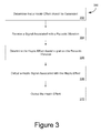
- Figure 3 is a flow chart describing an exemplary embodiment for a method for haptics in vibrating environments or devices.
- the stages in Figure 3 may be implemented in program code that is executed by a processor, for example, the processor in a general purpose computer, a mobile device, or server. These stages may be implemented by a group of processors, for example, a processor on a mobile device and processors on one or more general purpose computers, such as servers.
- the stages below are described with regard to the components of device 102 described above with regard to Figure 1 .
- the method 300 starts at stage 302 when processor 110 determines that a haptic effect should be generated.
- processor 110 may determine that a haptic effect should be generated as an alert associated with some component of the device 102.
- the haptic effect may be associated with the current battery level, the presence of a network or other type of connection, or some other features associated with the operation of the device.
- the haptic effect may be associated with a task or application on the mobile device, for example, the haptic effect may be associated with a GPS application and comprise an indication that the user has arrived at a particular location.
- the haptic effect may comprise an indication that a file has been downloaded, or that some operation or task has been completed.
- processor 110 receives a signal associated with a parasitic vibration.
- the signal may be received from memory 112, which may comprise a database associated with parasitic vibrations.
- memory 112 may comprise a database of one or more templates of parasitic vibrations.
- These templates may comprise data associated with parasitic vibrations in common environments.
- the templates may comprise data associated with vibrations on or in: an airplane (e.g. in various levels of turbulence), a bus on various types of roads, a car on various types of roads, or another environment associated with background vibrations.
- the signal may be received from sensor 120, which is configured to detect the parasitic vibrations.
- Sensor 120 may comprise, for example, an accelerometer.
- sensor 120 may comprise a component of haptic output device 118.
- haptic output device 118 may comprise a piezoelectric element.
- the piezoelectric element may be configured to output a signal associated with the parasitic vibrations of device 102.
- This signal may comprise data such as the magnitude or frequency of the parasitic vibration.
- the signal may be received from a location system (e.g. GPS or AGS) that provides the current location and/or velocity.
- processor 110 may determine the user's current location and data about the vibration based on this information. For example, if processor 110 determines that the user is traveling at above a certain speed on the Interstate, other road or railway, processor 110 may determine that a specific type of corresponding parasitic vibration is likely present.
- processor 110 determines a haptic effect based in part on the parasitic vibration.
- the haptic effect may be a haptic effect configured to compensate for the parasitic vibrations.
- the haptic effect may comprise a vibration based effect configured to be felt in spite of the parasitic vibration, e.g. a haptic effect at a different frequency and/or amplitude than the vibration and thus distinguishable from the parasitic vibration.
- processor 110 may ensure that any haptic effect is not output at a resonant frequency of the parasitic vibration by multiplying the frequency of the parasitic vibration by a fractional value (e.g. 1.3 or 1.7).
- processor 110 may perform a Fast Fourier Transform (FFT) of the parasitic vibration to select frequency components that are not represented or not strongly represented by the parasitic vibration.
- FFT Fast Fourier Transform
- the haptic effect may comprise an effect configured to compensate for the parasitic vibrations in other ways.
- the haptic effect may comprise a vibration at a frequency and amplitude configured to compensate for, mask, interfere with, reduce, or cancel the parasitic vibration.
- the haptic effect may comprise a vibration at substantially the same frequency and amplitude as the parasitic vibration, but offset by 180 degrees, and thus configured to substantially cancel the effect of the parasitic vibration.
- the same or another actuator which supplies the vibration which cancels or attenuates the parasitic vibration may output another haptic effect intended to be sensed as haptic feedback by a user of the device.
- the haptic effect may comprise an effect that is clearly distinguishable from the parasitic vibration and thus the parasitic vibration will have little or no effect on the haptic effect.
- the haptic effect may comprise a skin stretching effect, an electrostatic based effect, or a surface deformation effect.
- the haptic effect may comprise an effect configured to vary the perceived coefficient of friction on the surface of user input device 114.
- the haptic effect may comprise an effect configured to raise or lower a segment of user input device 114 (e.g. create a surface deformation on user input device 114).
- the haptic effect may comprise moving user input device 114, or a component of user input device 114, in a way that is perceptible to the user.
- the haptic effect may comprise an effect that is not associated with vibrations, and is thus perceptible despite the parasitic vibration.
- the parasitic vibration may comprise a vibration associated with the normal operation of the device.
- the device may comprise, an electric razor, a kitchen appliance, or piece of industrial equipment.
- the parasitic vibration may be generated by a motor or other component on the device.
- the haptic effect may be associated with controlling this motor or component, e.g. briefly stopping or slowing its operation, and thus generating a perceptible haptic effect by stopping or slowing the parasitic vibration.
- a housing of the device may comprise a magnetorheological fluid, which changes viscosity when a magnetic field is applied.
- the magnetorheological fluid may comprise a mechanical coupling between the component and the housing or between a part of the housing touched or held by the user and another part of the housing to which the component is mechanically coupled, e.g. mounted.
- a magnetic field may be applied to vary the strength of the parasitic vibration.
- the user may detect this change in the parasitic vibration as a haptic effect.
- the device may comprise one or more (e.g. adjustable) air sacs or shock absorbers that are used to vary the strength of the parasitic vibration and thus output a detectible haptic effect.
- Next processor 110 outputs a haptic signal associated with the haptic effect 308.
- This haptic signal may be a digital or analog signal comprising the data needed for haptic output device 118 to output the haptic effect.
- the haptic signal may be an analog drive signal for a haptic output device, or the haptic signal may be a high-level signal comprising parametric information describing the haptic effect to be output (e.g. a command identifier and associated parameters).
- haptic output device 118 may comprise the internal capability of determining and outputting a haptic effect based on the command identifier and associated parameters.
- haptic output device 118 outputs the haptic effect.
- This haptic effect may comprise a vibration effect, which as described above is configured to be distinguishable from the parasitic effect. Additionally or alternatively, it may comprise a different type of haptic effect, for example, an electrostatic friction effect, a surface deformation effect, or a skin stretch effect, configured to be felt distinctly from the parasitic vibration.
- Figure 4A is an illustration of a system for providing haptics in vibrating environments or devices.
- Figure 4A comprises system 400, which may be mounted inside the housing of a device according to the present disclosure.
- the system comprises a motor 416 connected to a gear 404 via a shaft 402.
- This motor may be configured to perform various tasks.
- motor 416 comprises the motor on a household appliance, such as a blender, coffee grinder, hand mixer, or some other known appliance.
- motor 416 comprises a motor for use in industrial or commercial applications.
- motor 416 may be a motor for use in a drill, saw, sander, or some other industrial tool.
- system 400 further comprises a braking mechanism 406 and brake 408, configured to brake gear 404 or some other part of the motor416 or its drive train or its driven element (not shown).
- a processor determines a haptic effect to be output
- the processor transmits a trigger signal to braking mechanism 406.
- braking mechanism 406 pulls brake 408 against gear 404, thus slowing gear 404 and any co-driven components.
- gear 404 etc. slows, a torque is output on system 400 which may then be imparted on a device incorporating the system 400.
- the intensity of the torque is associated with the braking force applied to gear 404.
- braking mechanism 406 may be configured to apply varying pressures on gear 404 to provide varying levels of torque.
- the processor may determine a weak haptic effect.
- braking mechanism 406 causes the brake 408 to press lightly against the gear 404 to slow it only slightly, thereby outputting a small torque.
- the processor may determine a strong haptic effect.
- braking mechanism 406 causes the brake 408 to press against the gear 404 to rapidly slow it and thereby output a strong torque (e.g. bringing gear 404 etc. to a complete stop in less than a full rotation - although the magnitude of the deceleration is the main reaction torque defining factor, and neither complete stoppage nor a duration of less than one rotation is necessary).
- Gear 404 may be substituted by any other suitable drivetrain component capable of being braked and undergoing the required changes in angular momentum.
- the system shown in Figure 4A may operate differently.
- braking mechanism 406 may not be present.
- electric motor 416 may be configured to output the haptic effect by quickly accelerating gear 404 or a flywheel or another mass coupled to the shaft 402 (not shown in Figure 4A ), and thereby output a torque.
- the system 400 may further comprise an energy store such as a capacitor or battery, configured to store and release energy to allow electric motor 416 to accelerate gear 404 quickly enough to output a torque.
- FIG 4B is an illustration of another system for haptics in vibrating environments or devices.
- system 450 comprises a flywheel 452, moveable weights 454, and track 456.
- Flywheel 452 is configured to be rotated by an electric or other motor or actuator.
- an electric motor associated with one of the devices discussed above with regard to Figure 4A .
- the positions of the moveable weights 454 may be configured for example based on the application of a magnetic field.
- the moveable weights 454 may comprise a material that is responsive to applied magnetic fields, such as iron or some composite materials.
- the moveable weights 454 may comprise magnets.
- a magnetic coil may encircle the flywheel 452 and be activated to draw the moveable weights 454 to the outer edge of the flywheel, or to return the moveable weights 454 to the center of the flywheel.
- the moveable weights 454 may be held at or near a rest position, such as near the center of the flywheel 452 by springs to resist centrifugal forces while the flywheel is spinning. Such springs may then be overpowered by the application of a magnetic field to draw the moveable weights 454 to the edge of the flywheel 452.
- flywheel 452 When the moveable weights 454 move, they change the distribution of mass on the flywheel 452 and thus change the angular momentum of flywheel 452. This change in angular momentum causes flywheel 452 to output a force on the motor that is rotating it.
- the user holding the handheld device that the actuator is associated with may feel this force as a haptic effect.
- this haptic effect may comprise rotating, or torqueing the handheld device in the user's hand.
- track 456 comprises a groove cut along a straight line or other linear guide passing through the center axis of flywheel 452.
- track 456 may comprise a different configuration.
- track 456 may be configured to keep both weights 454 at the center of flywheel 456 when a haptic effect is not being output. But when flywheel 452 receives a trigger signal .from the processor, track 456 may be configured to allow weights 454 to move to the same part of flywheel 452 to provide an eccentric rotating mass. Different numbers of weights may be used; including a single weight in the case of controllably providing an eccentric rotating mass
- system 450 comprises two weights 454 and one track 456.
- a different number of weights and tracks may be used.
- flywheel 452 may comprise three weights, and each weight may comprise its own track.
- the haptic effect may instead be output by modifying a component of the housing in which the electric motor is placed.
- a housing of the device may comprise a magnetorheological fluid, which changes viscosity when a magnetic field is applied.
- a magnetic field may be applied to vary the strength of the parasitic vibration.
- the user may detect this change in the parasitic vibration as a haptic effect.
- the device may comprise one or more air sacs or shock absorbers that are used to vary the strength of the parasitic vibration and thus output a detectible haptic effect.
- FIG. 5 another system for haptics in a vibrating device is shown.
- system 500 which comprises an electric razor 502.
- the electric razor 502 comprises an electric motor, which outputs a parasitic vibration when in operation.
- Electric Razor 502 may implement a system for outputting a haptic effect in a vibrating device in order to provide haptic feedback to the user. This may comprise one of the systems described above with regard to Figures 4A and 4B . Additionally or alternatively it may comprise making other changes to the operation of the electric motor in order to output a perceptible haptic effect.
- This haptic effect may be associated with data associated with Electric Razor 502's operation.
- the haptic effect may be associated with the current battery level of the device, i.e. a strong haptic effect may be associated with a warning that the battery level is low. Additionally or alternatively, the haptic effect(s) may be associated with other operational information, e.g. operating time, device setting (e.g. trimmer length), and/or the temperature of the motor of the device.
- operational information e.g. operating time, device setting (e.g. trimmer length), and/or the temperature of the motor of the device.
- Embodiments of the present disclosure provide numerous advantages over conventional methods of providing haptic feedback. For example, embodiments described herein make haptic effects usable in devices that are prone to vibration. This may be useful for mobile devices that users carry into vibrating environments. Similarly, this may be useful for incorporating haptics into new locations, for example, control systems in cars, airplanes, trains, or buses, or other vibration prone apparatus and environments.
- embodiments of the present disclosure may enable haptics to be incorporated into devices that already output some vibrations. This may enable haptics to be incorporated into industrial applications and also household appliances. This will lead to these devices being more usable, as users will be able to receive information from devices through more than the traditional senses of sight and sound. This will ultimately lead to greater user satisfaction, and more efficient use of these devices.
- configurations may be described as a process that is depicted as a flow diagram or block diagram. Although each may describe the operations as a sequential process, many of the operations can be performed in parallel or concurrently. In addition, the order of the operations may be rearranged. A process may have additional steps not included in the figure.
- examples of the methods may be implemented by hardware, software, firmware, middleware, microcode, hardware description languages, or any combination thereof. When implemented in software, firmware, middleware, or microcode, the program code or code segments to perform the necessary tasks may be stored in a non-transitory computer-readable medium such as a storage medium. Processors may perform the described tasks.
- a computer may comprise a processor or processors.
- the processor comprises or has access to a computer-readable medium, such as a random access memory (RAM) coupled to the processor.
- RAM random access memory
- the processor executes computer-executable program instructions stored in memory, such as executing one or more computer programs including a sensor sampling routine, selection routines, and other routines to perform the methods described above.
- Such processors may comprise a microprocessor, a digital signal processor (DSP), an application-specific integrated circuit (ASIC), field programmable gate arrays (FPGAs), and state machines.
- Such processors may further comprise programmable electronic devices such as PLCs, programmable interrupt controllers (PICs), programmable logic devices (PLDs), programmable read-only memories (PROMs), electronically programmable read-only memories (EPROMs or EEPROMs), or other similar devices.
- Such processors may comprise, or may be in communication with, media, for example tangible computer-readable media, that may store instructions that, when executed by the processor, can cause the processor to perform the steps described herein as carried out, or assisted, by a processor.
- Such computer-readable media may comprise, but are not limited to, all electronic, optical, magnetic, or other storage devices capable of providing a processor, such as the processor in a web server, with computer-readable instructions.
- Other examples of media comprise, but are not limited to, a floppy disk, CD-ROM, magnetic disk, memory chip, ROM, RAM, ASIC, configured processor, all optical media, all magnetic tape or other magnetic media, or any other medium from which a computer processor can read.
- various other devices may include or comprise or provide computer-readable media, such as a router, private or public network, or other transmission device.
- the processor, and the processing, described may be in one or more structures, and may be dispersed through one or more structures.
- the processor may comprise code for carrying out one or more of the methods (or parts of methods) described herein.
Abstract
Description
- The present invention generally relates to haptic feedback, and more particularly to systems and methods for haptic feedback in vibrating environments and devices.
- Haptic feedback can provide a conduit for electronic devices to communicate information to users. This conduit can be in addition to standard visual or auditory effects. The number of devices that include some form of haptic feedback has increased dramatically over the past several years. However, some of these devices already output vibrations, for example, as a byproduct of their regular operation. Further, many devices may be used in a vibrating environment. Either of these may dull or overwhelm haptic effects. Accordingly, there is a need for a device to compensate for these background vibrations.
- Embodiments of the present disclosure include devices featuring haptics in vibrating environments and devices. A system according to the present disclosure may comprise: a haptic output device; a processor coupled to the haptic output device, the processor configured to: determine that a haptic effect should be generated; receive a signal associated with a parasitic vibration; determine a haptic effect based in part on the parasitic vibration; and output a haptic signal associated with the haptic effect to the haptic output device.
- The invention is described with reference to illustrative embodiments which are mentioned not to limit or define the limits of the present subject matter, but to provide examples to aid understanding thereof. Illustrative embodiments are discussed in the Detailed Description, and further description is provided there. Advantages offered by various embodiments may be further understood by examining this specification and/or by practicing one or more embodiments of the claimed subject matter.
- These and other features, aspects, and advantages of the present disclosure are better understood when the following Detailed Description is read with reference to the accompanying drawings, wherein:
-
Figure 1 is a block diagram of systems and methods for haptics in vibrating environments and devices according to one embodiment; -
Figure 2 is an illustration of one embodiment of a system for haptics in vibrating environments and devices; -
Figure 3 is an illustration of a flow chart of one embodiment of a method for haptics in vibrating environments and devices; -
Figure 4A is an illustration of one embodiment of a system for haptics in vibrating devices; -
Figure 4B is an illustration of another embodiment of a system for haptics in vibrating devices; and -
Figure 5 is an illustration of another embodiment of a system for haptics in vibrating devices. - Several illustrative embodiments will now be described with respect to the accompanying drawings, which form a part hereof. While particular embodiments, in which one or more aspects of the disclosure may be implemented, are described below, other embodiments may be used and various modifications may be made without departing from the scope of the invention as defined by the appended claims.
- One illustrative embodiment of the present disclosure comprises a device that may be used in an environment prone to vibration, for example, a smartphone or other device comprising a haptic output device and a user interface through which the user feels haptic effects. A mobile device of the illustrative embodiment may be used in for example, a car, an airplane, a bus, a train, or some other environment that has substantial vibrations. These parasitic vibrations may interfere with the haptic effects output by the illustrative mobile device. For example, a parasitic vibration may mask a vibration output by the haptic output device.
- The illustrative embodiment of the present disclosure comprises systems for compensating for these parasitic vibrations. For example, the illustrative embodiment may comprise a data store comprising data associated with the parasitic vibrations. This data store may be local to the mobile device, or accessible via a network connection. Thus, in the illustrative embodiment, when the user is in a location associated with parasitic vibrations the illustrative mobile device may receive a signal from the data store. Based on this signal, the illustrative mobile device may determine a haptic effect that is distinguishable from the parasitic vibration.
- This distinguishable haptic effect may comprise one or more of many potential haptic effects. For example, the haptic effect may comprise a vibration based effect configured to be felt in spite of the parasitic vibration, e.g. a haptic effect at a different frequency and/or amplitude than the vibration and thus distinguishable from the parasitic vibration. Additionally or alternatively, the haptic effect may comprise an effect configured to compensate for the parasitic vibrations. For example, the haptic effect may comprise a vibration at a frequency and amplitude configured to compensate for, or mask (e.g. "reduce" or "cancel") the parasitic vibration.
- The haptic effect may comprise a skin stretching effect, an electrostatic based effect, or a surface deformation effect. The parasitic vibration may have little or no impact on the haptic effect. Further, the haptic effect may comprise a non-vibration based effect.
- The haptic effect may comprise an effect configured to control the parasitic vibration. For example, the parasitic vibration may be the result of the normal operation of the device. The device may for example comprise a motor or other component that outputs the parasitic vibration. The haptic effect may comprise controlling the motor or other component to vary the parasitic vibration, and thus output a perceptible haptic effect.
- Thus, the mobile or other device may output a haptic effect that the user can perceive despite the parasitic vibration. This may enable the user to use the illustrative device in a vibrating environment, e.g. in a car, train, or airplane.
- The device may be incorporated into the vibrating environment. For example, the illustrative device may comprise a touch screen display for use in a car stereo or a touch screen for use in an airplane entertainment system. In such an embodiment, the device may output a haptic effect that is distinguishable from the vibration of the larger system (e.g. the vibration as the car moves over the road or as the airplane experiences turbulence).
- Additionally or alternatively, the device may be a device that already includes a vibration, e.g. an electric razor, a kitchen appliance, or piece of industrial equipment. The parasitic vibration may be generated by a motor or other component on the device which normally serves a purpose other than for generating haptic effects. Thus, the haptic effect may be associated with controlling this motor or the like, e.g. briefly stopping or slowing its operation, and thus generating a perceptible haptic effect by stopping or slowing the parasitic vibration.
- These illustrative examples are given to introduce the reader to the general subject matter discussed herein. The invention is not limited to these examples. The following sections describe various additional embodiments and examples of systems and methods for haptics in vibrating environments
- Referring now to the drawings in which like numerals indicate like elements throughout the several Figures,
Figure 1 is a block diagram of a system for haptics in vibrating environments and devices according to one embodiment of the disclosure. - The
system 100 shown inFigure 1 comprises adevice 102.Device 102 may comprise one of a variety of handheld devices, such as a mobile phone, a personal digital assistant (PDA), or a handheld navigation system. Alternatively, the present disclosure may be implemented in a device that is not portable, for example, in an automobile console, an airplane console, a console for industrial equipment, a household appliance, a gaming console, or other device, whether primarily electronic or not. - Embodiments of the present disclosure can be implemented in combination with, or may comprise combinations of: digital electronic circuitry, computer hardware, firmware, and software. The
device 102 shown inFigure 1 comprises aprocessor 110. Theprocessor 110 receives input signals and generates signals for communication, display, and providing haptic feedback. Theprocessor 110 includes or is in communication with one or more computer-readable media, such asmemory 112, which may comprise random access memory (RAM). - The
processor 110 executes computer-executable program instructions stored inmemory 112, such as executing one or more computer programs for messaging or for generating haptic feedback.Processor 110 may comprise a microprocessor, a digital signal processor (DSP), an application-specific integrated circuit (ASIC), one or more field programmable gate arrays (FPGAs), or state machines. The processor may further comprise a programmable electronic device such as a PLC, a programmable interrupt controller (PIC), a programmable logic device (PLD), a programmable read-only memory (PROM), an electronically programmable read-only memory (EPROM or EEPROM), or other similar devices. -
Memory 112 comprises a computer-readable medium that may store instructions, which, when executed by theprocessor 110, cause it to perform various steps, such as those described herein. Suitable computer-readable media may comprise, but are not limited to, non-transient computer readable media such as, an electronic, optical, magnetic, or other storage or transmission device capable of providing theprocessor 110 with computer-readable instructions. Other examples of media comprise, but are not limited to, a floppy disk, CD-ROM, magnetic disk, memory chip, ROM, RAM, ASIC, configured processor, all optical media, all magnetic tape or other magnetic media, or any other medium from which a computer processor can read. Also, various other devices may include or comprise or constitute suitable computer-readable media, such as a router, private or public network, or other transmission device. Thus thememory 112 may be internal to or external of thedevice 102. Theprocessor 110, and the processing, described may be in one or more structures, and may be dispersed throughout one or more structures. -
Memory 112 may further comprise a data store comprising data associated with the parasitic vibrations. For example,memory 112 may comprise a database of parasitic vibrations associated with various environments, which is accessible byprocessor 110. For example, in some embodiments,memory 112 may comprise a database of one or more templates of parasitic vibrations. These templates may comprise data associated with parasitic vibrations in common environments. For example, the templates may comprise data associated with vibrations: on an airplane (e.g. in various levels of turbulence), a bus on various types of roads, a car on various types of roads, or another environment associated with background vibrations. - Referring still to
Figure 1 , thedevice 102 also comprises auser input device 114 in communication with theprocessor 110. For example, theuser input device 114 may comprise a touchscreen.User input device 114 may sense user interaction as well as the location of the interaction. For example the user input device may comprise a capacitance-based touchscreen. Additionally or alternatively,user input device 114 may comprise a button, switch, slider, or trackball. Thedevice 102 may comprise both a touch screen and an additionaluser input device 114, or a non-touch sensitive screen and a user input device. - The
device 102 also comprises adisplay 116.Display 116 is in communication withprocessor 110 and is configured to display output from theprocessor 110 to the user. For instance, thedevice 102 may comprise a liquid crystal display (LCD) disposed beneath theuser input device 114. Thedisplay 116 anduser input device 114 may comprise a single, integrated component, such as a touch-screen LCD. Alternatively,device 102 may not comprise a display. - The
device 102 also comprises ahaptic output device 118, which is in communication with theprocessor 110 and configured to output a haptic effect. Theprocessor 110 outputs a haptic signal to thehaptic output device 118, which then outputs a haptic effect based on the haptic signal. For instance, theprocessor 110 may output a haptic signal designed to cause thehaptic output device 118 to vibrate. Additionally or alternatively, in response to the haptic signal,haptic output device 118 may output a different type of haptic effect. For example,haptic output device 118 may be configured to output a haptic effect varying a perceived coefficient of friction of a touch surface. Additionally or alternatively,haptic output device 118 may provide vibrotactile haptic effects that moveuser input device 114, or other components ofdevice 102, in a controlled manner. -
Haptic output device 118 may comprise an actuator coupled to a housing of thedevice 102, and some haptic effects may use multiple actuators in sequence and/or in concert. For example, the perceptible coefficient of friction can be varied by vibrating the surface at varying frequencies above a threshold. Different combinations/sequences of variance can be used to simulate other effects. - Although a single
haptic output device 118 is shown inFigure 1 , multiple haptic output devices of the same or different type may be used to output varying types of effects. For example, a piezoelectric actuator may be used to displace some or all of a touch surface vertically and/or horizontally at ultrasonic frequencies, such as by using an actuator moving at frequencies greater than 20kHz. Multiple actuators such as eccentric rotating mass motors and linear resonant actuators can be used alone or in concert to provide other haptic effects. Additionally or alternatively,haptic output device 118 may comprise an electrostatic actuator, or an actuator configured to modify the shape of one or more components ofdevice 102. - Additionally or alternatively,
haptic output device 118 may comprise a device configured to vary a vibration output by a motor or other component ondevice 102. For example,haptic output device 118 may comprise an additional mass to be applied to the motor in order to vary the rotation of that motor and generate a vibration. In another embodiment,haptic output device 118 may comprise a device configured to vary a structural characteristic of a housing or a mount associated with the motor. This may vary the parasitic vibration in a way that is perceptible to the user ofdevice 102. - The
device 102 also comprises asensor 120. Thesensor 120 is configured to detect a parasitic vibration, and transmit a signal associated with the parasitic vibration to theprocessor 110.Sensor 120 may be a component ofhaptic output device 118. For example,haptic output device 118 may comprise a piezoelectric actuator that also serves as a sensor to detect parasitic vibrations. Additionally or alternatively,sensor 120 may comprise another type of vibration detection device, for example, an accelerometer. Additionally or alternatively,sensor 120 may comprise a sensor configured to determine the location ofdevice 102. For example,sensor 120 may comprise a GPS sensor configured to determine whether thedevice 102 is currently in an area associated with a specific type of parasitic vibration, e.g. a road, a train, an airplane, or some other location associated with a parasitic vibration.Sensor 120 is not a required component ofdevice 102. - Turning now to
Figures 2A-2B , which illustrate an example of a system for haptics in vibrating environments or devices.Figure 2A is a diagram illustrating an external view of asystem 200 comprising acomputing device 201 that comprises a touch-enableddisplay 202.Figure 2B shows a cross-sectional view ofdevice 201.Device 201 may be configured similarly todevice 102 described above with regard toFigure 1 , though components such as the processor, memory, sensors, and the like are not shown in this view for purposes of clarity. - As can be seen in
Figure 2B ,device 201 includes a plurality of haptic output devices 218 and an additionalhaptic output device 222. Haptic output device(s) 218-1 may comprise an actuator configured to impart vertical force to display 202, while 218-2 may movedisplay 202 laterally. In this example, the haptic output devices are coupled directly to the display, but it should be understood that the actuators could be coupled to another touch surface, such as a layer of material on top ofdisplay 202.Additional actuator 222 may be coupled to a housing containing the components ofdevice 201. In the examples ofFigures 2A-2B , the area ofdisplay 202 corresponds to the touch area, though the principles could be applied to a touch surface completely separate from the display. - Haptic output devices 218 may each comprise a piezoelectric actuator, while
additional actuator 222 may comprise an eccentric rotating mass motor, a linear resonant actuator, or another piezoelectric actuator.Actuator 222 can be configured to provide a vibrotactile haptic effect in response to a haptic signal from the processor. The vibrotactile haptic effect can be utilized in conjunction with surface-based haptic effects and/or for other purposes. - Either or both haptic output devices 218-1 and 218-2 can comprise an actuator such as a piezoelectric actuator. Additionally or alternatively, haptic output devices 218-1 and 218-2 may comprise an electromagnetic actuator, an electroactive polymer, a shape memory alloy, a flexible composite piezo actuator (e.g. an actuator comprising a flexible material), electrostatic, and/or magnetostrictive actuators. Additionally, a
single actuator 222 is shown, although multiple other haptic output devices can be coupled to the housing ofdevice 201 and/orother actuators 222 may be coupled elsewhere. Alternatively, one or more of the actuators 218-1 and 218-2, or theactuator 222, may be omitted.Device 201 may feature multiple haptic output devices 218-1 / 218-2 coupled to the touch surface at different locations, as well. - Turning back to
Figure 2A , a user may interact with touch enableddisplay 202. And in response to the user interaction, one or more of the haptic output devices 218-1 / 218-2 may output a haptic effect. However, themobile device 201 may be used in an area comprising significant parasitic vibrations. In such circumstances, the haptic effect may be tuned to be perceptible despite the parasitic vibrations. Thus, when the device is in an area associated with parasitic vibrations, the haptic effect may comprise a haptic effect that is clearly distinguishable from the parasitic vibration. This effect may comprise, for example, an electrostatic based effect, a skin stretch effect, or a surface deformation effect. Further, this effect may comprise a non-vibration based effect. When the device is no longer in an area associated with parasitic vibrations, the haptic effect may comprise a vibration based effect. - Referring now to
Figure 3, Figure 3 is a flow chart describing an exemplary embodiment for a method for haptics in vibrating environments or devices. The stages inFigure 3 may be implemented in program code that is executed by a processor, for example, the processor in a general purpose computer, a mobile device, or server. These stages may be implemented by a group of processors, for example, a processor on a mobile device and processors on one or more general purpose computers, such as servers. The stages below are described with regard to the components ofdevice 102 described above with regard toFigure 1 . - As shown in
FIG. 3 , themethod 300 starts atstage 302 whenprocessor 110 determines that a haptic effect should be generated. For example,processor 110 may determine that a haptic effect should be generated as an alert associated with some component of thedevice 102. For example, the haptic effect may be associated with the current battery level, the presence of a network or other type of connection, or some other features associated with the operation of the device. The haptic effect may be associated with a task or application on the mobile device, for example, the haptic effect may be associated with a GPS application and comprise an indication that the user has arrived at a particular location. As another example, the haptic effect may comprise an indication that a file has been downloaded, or that some operation or task has been completed. - Continuing to step 304 when
processor 110 receives a signal associated with a parasitic vibration. The signal may be received frommemory 112, which may comprise a database associated with parasitic vibrations. For example,memory 112 may comprise a database of one or more templates of parasitic vibrations. These templates may comprise data associated with parasitic vibrations in common environments. For example, the templates may comprise data associated with vibrations on or in: an airplane (e.g. in various levels of turbulence), a bus on various types of roads, a car on various types of roads, or another environment associated with background vibrations. - Additionally or alternatively, the signal may be received from
sensor 120, which is configured to detect the parasitic vibrations.Sensor 120 may comprise, for example, an accelerometer. Alternatively,sensor 120 may comprise a component ofhaptic output device 118. For example,haptic output device 118 may comprise a piezoelectric element. Further, the piezoelectric element may be configured to output a signal associated with the parasitic vibrations ofdevice 102. This signal may comprise data such as the magnitude or frequency of the parasitic vibration. Yet alternatively, the signal may be received from a location system (e.g. GPS or AGS) that provides the current location and/or velocity. In such case,processor 110 may determine the user's current location and data about the vibration based on this information. For example, ifprocessor 110 determines that the user is traveling at above a certain speed on the Interstate, other road or railway,processor 110 may determine that a specific type of corresponding parasitic vibration is likely present. - At
stage 306processor 110 determines a haptic effect based in part on the parasitic vibration. The haptic effect may be a haptic effect configured to compensate for the parasitic vibrations. For example, the haptic effect may comprise a vibration based effect configured to be felt in spite of the parasitic vibration, e.g. a haptic effect at a different frequency and/or amplitude than the vibration and thus distinguishable from the parasitic vibration. For example,processor 110 may ensure that any haptic effect is not output at a resonant frequency of the parasitic vibration by multiplying the frequency of the parasitic vibration by a fractional value (e.g. 1.3 or 1.7). Additionally or alternativelyprocessor 110 may perform a Fast Fourier Transform (FFT) of the parasitic vibration to select frequency components that are not represented or not strongly represented by the parasitic vibration. - The haptic effect may comprise an effect configured to compensate for the parasitic vibrations in other ways. For example, the haptic effect may comprise a vibration at a frequency and amplitude configured to compensate for, mask, interfere with, reduce, or cancel the parasitic vibration. For example, the haptic effect may comprise a vibration at substantially the same frequency and amplitude as the parasitic vibration, but offset by 180 degrees, and thus configured to substantially cancel the effect of the parasitic vibration. The same or another actuator which supplies the vibration which cancels or attenuates the parasitic vibration, may output another haptic effect intended to be sensed as haptic feedback by a user of the device.
- Additionally or alternatively, the haptic effect may comprise an effect that is clearly distinguishable from the parasitic vibration and thus the parasitic vibration will have little or no effect on the haptic effect. For example, the haptic effect may comprise a skin stretching effect, an electrostatic based effect, or a surface deformation effect. For example, the haptic effect may comprise an effect configured to vary the perceived coefficient of friction on the surface of
user input device 114. Additionally or alternatively, the haptic effect may comprise an effect configured to raise or lower a segment of user input device 114 (e.g. create a surface deformation on user input device 114). The haptic effect may comprise movinguser input device 114, or a component ofuser input device 114, in a way that is perceptible to the user. As another example, the haptic effect may comprise an effect that is not associated with vibrations, and is thus perceptible despite the parasitic vibration. These various examples are not mutually exclusive and are non-limiting. - The parasitic vibration may comprise a vibration associated with the normal operation of the device. For example, the device may comprise, an electric razor, a kitchen appliance, or piece of industrial equipment. Thus, the parasitic vibration may be generated by a motor or other component on the device. In such case, the haptic effect may be associated with controlling this motor or component, e.g. briefly stopping or slowing its operation, and thus generating a perceptible haptic effect by stopping or slowing the parasitic vibration. For example, a housing of the device may comprise a magnetorheological fluid, which changes viscosity when a magnetic field is applied. The magnetorheological fluid may comprise a mechanical coupling between the component and the housing or between a part of the housing touched or held by the user and another part of the housing to which the component is mechanically coupled, e.g. mounted. Thus, a magnetic field may be applied to vary the strength of the parasitic vibration. The user may detect this change in the parasitic vibration as a haptic effect. In another embodiment, the device may comprise one or more (e.g. adjustable) air sacs or shock absorbers that are used to vary the strength of the parasitic vibration and thus output a detectible haptic effect.
-
Next processor 110 outputs a haptic signal associated with thehaptic effect 308. This haptic signal may be a digital or analog signal comprising the data needed forhaptic output device 118 to output the haptic effect. The haptic signal may be an analog drive signal for a haptic output device, or the haptic signal may be a high-level signal comprising parametric information describing the haptic effect to be output (e.g. a command identifier and associated parameters). In such case,haptic output device 118 may comprise the internal capability of determining and outputting a haptic effect based on the command identifier and associated parameters. - At
stage 310,haptic output device 118 outputs the haptic effect. This haptic effect may comprise a vibration effect, which as described above is configured to be distinguishable from the parasitic effect. Additionally or alternatively, it may comprise a different type of haptic effect, for example, an electrostatic friction effect, a surface deformation effect, or a skin stretch effect, configured to be felt distinctly from the parasitic vibration. - Referring now to
Figures 4A and 4B, Figure 4A is an illustration of a system for providing haptics in vibrating environments or devices.Figure 4A comprisessystem 400, which may be mounted inside the housing of a device according to the present disclosure. As shown inFigure 4A , the system comprises amotor 416 connected to agear 404 via ashaft 402. This motor may be configured to perform various tasks. For example, in one embodiment,motor 416 comprises the motor on a household appliance, such as a blender, coffee grinder, hand mixer, or some other known appliance. In other embodiments,motor 416 comprises a motor for use in industrial or commercial applications. For example,motor 416 may be a motor for use in a drill, saw, sander, or some other industrial tool. - When
motor 416 is in operation it outputs a vibration (described above as a parasitic vibration). Rather than using an additional vibration to output a haptic effect, the processor may instead output an effect associated with controlling this parasitic vibration. Accordingly, as shown inFigure 4A ,system 400 further comprises abraking mechanism 406 andbrake 408, configured tobrake gear 404 or some other part of the motor416 or its drive train or its driven element (not shown). - When a processor determines a haptic effect to be output, the processor transmits a trigger signal to
braking mechanism 406. In response,braking mechanism 406 pullsbrake 408 againstgear 404, thus slowinggear 404 and any co-driven components. Whengear 404 etc. slows, a torque is output onsystem 400 which may then be imparted on a device incorporating thesystem 400. The intensity of the torque is associated with the braking force applied togear 404. Thus,braking mechanism 406 may be configured to apply varying pressures ongear 404 to provide varying levels of torque. For example, the processor may determine a weak haptic effect. In such anevent braking mechanism 406 causes thebrake 408 to press lightly against thegear 404 to slow it only slightly, thereby outputting a small torque. In other instances, the processor may determine a strong haptic effect. In such an event,braking mechanism 406 causes thebrake 408 to press against thegear 404 to rapidly slow it and thereby output a strong torque (e.g. bringing gear 404 etc. to a complete stop in less than a full rotation - although the magnitude of the deceleration is the main reaction torque defining factor, and neither complete stoppage nor a duration of less than one rotation is necessary).Gear 404 may be substituted by any other suitable drivetrain component capable of being braked and undergoing the required changes in angular momentum. - The system shown in
Figure 4A may operate differently. For example,braking mechanism 406 may not be present. Instead,electric motor 416 may be configured to output the haptic effect by quickly acceleratinggear 404 or a flywheel or another mass coupled to the shaft 402 (not shown inFigure 4A ), and thereby output a torque. Thesystem 400 may further comprise an energy store such as a capacitor or battery, configured to store and release energy to allowelectric motor 416 to accelerategear 404 quickly enough to output a torque. -
Figure 4B is an illustration of another system for haptics in vibrating environments or devices. As shown inFigure 4B ,system 450 comprises aflywheel 452,moveable weights 454, andtrack 456.Flywheel 452 is configured to be rotated by an electric or other motor or actuator. For example, an electric motor associated with one of the devices discussed above with regard toFigure 4A . - The positions of the
moveable weights 454 may be configured for example based on the application of a magnetic field. For example, themoveable weights 454 may comprise a material that is responsive to applied magnetic fields, such as iron or some composite materials. Themoveable weights 454 may comprise magnets. For example, a magnetic coil may encircle theflywheel 452 and be activated to draw themoveable weights 454 to the outer edge of the flywheel, or to return themoveable weights 454 to the center of the flywheel. Themoveable weights 454 may be held at or near a rest position, such as near the center of theflywheel 452 by springs to resist centrifugal forces while the flywheel is spinning. Such springs may then be overpowered by the application of a magnetic field to draw themoveable weights 454 to the edge of theflywheel 452. - When the
moveable weights 454 move, they change the distribution of mass on theflywheel 452 and thus change the angular momentum offlywheel 452. This change in angular momentum causesflywheel 452 to output a force on the motor that is rotating it. The user holding the handheld device that the actuator is associated with may feel this force as a haptic effect. In some embodiments, this haptic effect may comprise rotating, or torqueing the handheld device in the user's hand. - In the embodiment shown in
Figure 4B ,track 456 comprises a groove cut along a straight line or other linear guide passing through the center axis offlywheel 452. In other embodiments track 456 may comprise a different configuration. For example, in one embodiment, track 456 may be configured to keep bothweights 454 at the center offlywheel 456 when a haptic effect is not being output. But whenflywheel 452 receives a trigger signal .from the processor, track 456 may be configured to allowweights 454 to move to the same part offlywheel 452 to provide an eccentric rotating mass. Different numbers of weights may be used; including a single weight in the case of controllably providing an eccentric rotating mass - In the embodiment shown in
Figure 4B ,system 450 comprises twoweights 454 and onetrack 456. In other embodiments, a different number of weights and tracks may be used. For example, in one embodiment,flywheel 452 may comprise three weights, and each weight may comprise its own track. - In other embodiments, not shown in
Figures 4A or 4B , rather than applying a brake or an eccentric rotating mass, the haptic effect may instead be output by modifying a component of the housing in which the electric motor is placed. For example, a housing of the device may comprise a magnetorheological fluid, which changes viscosity when a magnetic field is applied. Thus, a magnetic field may be applied to vary the strength of the parasitic vibration. The user may detect this change in the parasitic vibration as a haptic effect. In another embodiment, the device may comprise one or more air sacs or shock absorbers that are used to vary the strength of the parasitic vibration and thus output a detectible haptic effect. - Turning now to
Figure 5 another system for haptics in a vibrating device is shown. Shown inFigure 5 issystem 500, which comprises anelectric razor 502. Theelectric razor 502 comprises an electric motor, which outputs a parasitic vibration when in operation. Accordingly,Electric Razor 502 may implement a system for outputting a haptic effect in a vibrating device in order to provide haptic feedback to the user. This may comprise one of the systems described above with regard toFigures 4A and 4B . Additionally or alternatively it may comprise making other changes to the operation of the electric motor in order to output a perceptible haptic effect. This haptic effect may be associated with data associated withElectric Razor 502's operation. For example, the haptic effect may be associated with the current battery level of the device, i.e. a strong haptic effect may be associated with a warning that the battery level is low. Additionally or alternatively, the haptic effect(s) may be associated with other operational information, e.g. operating time, device setting (e.g. trimmer length), and/or the temperature of the motor of the device. - Embodiments of the present disclosure provide numerous advantages over conventional methods of providing haptic feedback. For example, embodiments described herein make haptic effects usable in devices that are prone to vibration. This may be useful for mobile devices that users carry into vibrating environments. Similarly, this may be useful for incorporating haptics into new locations, for example, control systems in cars, airplanes, trains, or buses, or other vibration prone apparatus and environments.
- Furthermore, embodiments of the present disclosure may enable haptics to be incorporated into devices that already output some vibrations. This may enable haptics to be incorporated into industrial applications and also household appliances. This will lead to these devices being more usable, as users will be able to receive information from devices through more than the traditional senses of sight and sound. This will ultimately lead to greater user satisfaction, and more efficient use of these devices.
- The methods, systems, and devices discussed above are examples. Various configurations may omit, substitute, or add various procedures or components as appropriate. For instance, in alternative configurations, the methods may be performed in an order different from that described, and/or various stages may be added, omitted, and/or combined. Also, features described with respect to certain configurations and embodiments may be combined with or used in various other configurations and embodiments. Different aspects and elements of the configurations may be combined in a similar manner. Also, technology evolves and, thus, many of the elements are examples and do not limit the scope of the disclosure or claims.
- Specific details are given in the description to provide a thorough understanding of example configurations (including implementations). However, configurations may be practiced without these specific details. For example, well-known circuits, processes, algorithms, structures, and techniques have been shown without unnecessary detail in order to avoid obscuring the configurations. This description provides example configurations only, and does not limit the scope, applicability, or configurations of the claims. Rather, the preceding description of the configurations will provide those skilled in the art with an enabling description for implementing described techniques. Various changes may be made in the function and arrangement of elements without departing from the scope of the invention as defined in the claims.
- Also, configurations may be described as a process that is depicted as a flow diagram or block diagram. Although each may describe the operations as a sequential process, many of the operations can be performed in parallel or concurrently. In addition, the order of the operations may be rearranged. A process may have additional steps not included in the figure. Furthermore, examples of the methods may be implemented by hardware, software, firmware, middleware, microcode, hardware description languages, or any combination thereof. When implemented in software, firmware, middleware, or microcode, the program code or code segments to perform the necessary tasks may be stored in a non-transitory computer-readable medium such as a storage medium. Processors may perform the described tasks.
- Having described several example configurations, various modifications, alternative constructions, and equivalents may be used without departing from the invention as defined by the claims. For example, the above elements may be components of a larger system, wherein other rules may take precedence over or otherwise modify the application of the disclosure. Also, a number of steps may be undertaken before, during, or after the above elements are considered. Accordingly, the above description does not bound the scope of the claims.
- The use of "adapted to" or "configured to" herein is meant as open and inclusive language that does not foreclose devices adapted to or configured to perform additional tasks or steps. Additionally, the use of "based on" is meant to be open and inclusive, in that a process, step, calculation, or other action "based on" one or more recited conditions or values may, in practice, be based on additional conditions or values beyond those recited. Headings, lists, and numbering included herein are for ease of explanation only and are not meant to be limiting.
- Embodiments in accordance with aspects of the present subject matter can be implemented in digital electronic circuitry, in computer hardware, firmware, software, or in combinations of the preceding. In one embodiment, a computer may comprise a processor or processors. The processor comprises or has access to a computer-readable medium, such as a random access memory (RAM) coupled to the processor. The processor executes computer-executable program instructions stored in memory, such as executing one or more computer programs including a sensor sampling routine, selection routines, and other routines to perform the methods described above.
- Such processors may comprise a microprocessor, a digital signal processor (DSP), an application-specific integrated circuit (ASIC), field programmable gate arrays (FPGAs), and state machines. Such processors may further comprise programmable electronic devices such as PLCs, programmable interrupt controllers (PICs), programmable logic devices (PLDs), programmable read-only memories (PROMs), electronically programmable read-only memories (EPROMs or EEPROMs), or other similar devices.
- Such processors may comprise, or may be in communication with, media, for example tangible computer-readable media, that may store instructions that, when executed by the processor, can cause the processor to perform the steps described herein as carried out, or assisted, by a processor. Such computer-readable media may comprise, but are not limited to, all electronic, optical, magnetic, or other storage devices capable of providing a processor, such as the processor in a web server, with computer-readable instructions. Other examples of media comprise, but are not limited to, a floppy disk, CD-ROM, magnetic disk, memory chip, ROM, RAM, ASIC, configured processor, all optical media, all magnetic tape or other magnetic media, or any other medium from which a computer processor can read. Also, various other devices may include or comprise or provide computer-readable media, such as a router, private or public network, or other transmission device. The processor, and the processing, described may be in one or more structures, and may be dispersed through one or more structures. The processor may comprise code for carrying out one or more of the methods (or parts of methods) described herein.
- While the present subject matter has been described in detail with respect to specific embodiments thereof, it will be appreciated that those skilled in the art, upon attaining an understanding of the foregoing may readily produce alterations to, variations of, and equivalents to such embodiments. Accordingly, it should be understood that the present disclosure has been presented for purposes of example rather than limitation, and does not preclude inclusion of such modifications, variations and/or additions to the present subject matter as would be readily apparent to one of ordinary skill in the art.
Claims (13)
- A system (100, 200, 300, 400, 500) comprising:a haptic output device (118, 218-1, 218-2, 222, 416), anda processor (110) coupled to the haptic output device, the processor configured to:(302) determine that a haptic effect should be generated;
characterized in that the processor is configured to:(304) receive a signal associated with a parasitic vibration;(306) determine the haptic effect based in part on the parasitic vibration; and(308) output a haptic signal associated with the haptic effect to the haptic output device. - The system (100, 200, 300, 400, 500) of claim 1, further comprising a user interface (114, 116, 202), and wherein the haptic output device (118, 218-1, 218-2, 222, 416) is configured to output the haptic effect to the user interface.
- The system (100, 200, 300, 400, 500) of claim 1 or 2, wherein the signal associated with the parasitic vibration is received (304) from a data store comprising data associated with parasitic vibrations, or is received from a sensor (120) configured to detect the parasitic vibrations, or is received from the haptic output device (118, 218-1, 218-2, 222) which is configured to detect the parasitic vibrations.
- The system (100, 200, 300, 400, 500) of claim 1, 2 or 3, wherein the haptic effect comprises an effect configured to be felt distinctly from the parasitic vibration.
- The system (100, 200, 300, 400, 500) of claim 4, wherein the haptic effect comprises one or more of: a vibration at a frequency different than the frequency of the parasitic vibration or a vibration at a frequency and amplitude configured to mask the parasitic vibration, or wherein outputting the haptic effect comprises varying the parasitic vibration, optionally by adjusting a feature (408, 454) of a component (400, 450) associated with the parasitic vibration.
- The system (100, 200, 300, 400, 500) of claim 4, wherein the haptic effect comprises one or more of: a non-vibration based effect, an electrostatic friction effect, a deformation of a user input device, or a skin stretch effect.
- A method (300) comprising:(302) determining that a haptic effect should be generated, and(310) outputting the haptic effect;
characterized by the steps of:(304) receiving a signal associated with a parasitic vibration;(306) determining the haptic effect based in part on the parasitic vibration, and(308) outputting a haptic signal associated with the haptic effect to a haptic output device (118, 218-1, 218-2, 222, 416). - The method (300) of claim 7, wherein the haptic output device (118, 218-1, 218-2, 222) is configured to output the haptic effect to a user interface (114, 116, 202).
- The method (300) of claim 7 or 8, wherein the signal associated with the parasitic vibration is received from a data store comprising data associated with parasitic vibrations, or is received from a sensor (120) configured to detect the parasitic vibrations, or is received from a haptic output device (118, 218-1, 218-2, 222) configured to detect the parasitic vibrations.
- The method (300) of claim 7, 8 or 9, wherein the haptic effect comprises an effect configured to be felt distinctly from the parasitic vibration.
- The method (300) of claim 10, wherein the haptic effect comprises one or more of: a vibration at a frequency different than the frequency of the parasitic vibration or a vibration at a frequency and amplitude configured to mask the parasitic vibration, or wherein outputting the haptic effect comprises varying the parasitic vibration, optionally by adjusting a feature (408, 454) of a component (400, 450) that is associated with the parasitic vibration.
- The method (300) of claim 10, wherein the haptic effect comprises one or more of: a non-vibration based effect, an electrostatic friction effect, a deformation of a user input device, or a skin stretch effect.
- A non-transient computer readable medium comprising program code, which when executed by a processor is configured to cause the processor to carry out the method (300) of any of claims 7-12.
Priority Applications (1)
| Application Number | Priority Date | Filing Date | Title |
|---|---|---|---|
| EP19201266.4A EP3608760A1 (en) | 2013-03-11 | 2014-03-06 | Systems and methods for haptic feedback in vibrating environments and devices |
Applications Claiming Priority (1)
| Application Number | Priority Date | Filing Date | Title |
|---|---|---|---|
| US13/792,337 US9202351B2 (en) | 2013-03-11 | 2013-03-11 | Systems and methods for haptics in vibrating environments and devices |
Related Child Applications (1)
| Application Number | Title | Priority Date | Filing Date |
|---|---|---|---|
| EP19201266.4A Division EP3608760A1 (en) | 2013-03-11 | 2014-03-06 | Systems and methods for haptic feedback in vibrating environments and devices |
Publications (2)
| Publication Number | Publication Date |
|---|---|
| EP2778845A2 true EP2778845A2 (en) | 2014-09-17 |
| EP2778845A3 EP2778845A3 (en) | 2017-04-19 |
Family
ID=50287864
Family Applications (2)
| Application Number | Title | Priority Date | Filing Date |
|---|---|---|---|
| EP14158123.1A Withdrawn EP2778845A3 (en) | 2013-03-11 | 2014-03-06 | Systems and methods for haptics in vibrating environments and devices |
| EP19201266.4A Withdrawn EP3608760A1 (en) | 2013-03-11 | 2014-03-06 | Systems and methods for haptic feedback in vibrating environments and devices |
Family Applications After (1)
| Application Number | Title | Priority Date | Filing Date |
|---|---|---|---|
| EP19201266.4A Withdrawn EP3608760A1 (en) | 2013-03-11 | 2014-03-06 | Systems and methods for haptic feedback in vibrating environments and devices |
Country Status (5)
| Country | Link |
|---|---|
| US (2) | US9202351B2 (en) |
| EP (2) | EP2778845A3 (en) |
| JP (2) | JP6463603B2 (en) |
| KR (1) | KR20140111609A (en) |
| CN (2) | CN104049730B (en) |
Cited By (4)
| Publication number | Priority date | Publication date | Assignee | Title |
|---|---|---|---|---|
| EP3208690A1 (en) * | 2016-02-22 | 2017-08-23 | Immersion Corporation | Haptic effects conflict avoidance |
| US10204493B2 (en) | 2015-09-16 | 2019-02-12 | Immersion Corporation | Haptic feedback in a haptically noisy environment |
| EP3480701A4 (en) * | 2016-07-08 | 2019-07-17 | Guangdong Oppo Mobile Telecommunications Corp., Ltd | Charging indication method, device and terminal |
| WO2020131670A1 (en) * | 2018-12-18 | 2020-06-25 | Immersion Corporation | Systems and methods for integrating environmental haptics in virtual reality |
Families Citing this family (30)
| Publication number | Priority date | Publication date | Assignee | Title |
|---|---|---|---|---|
| US9335822B2 (en) * | 2012-12-12 | 2016-05-10 | Immersion Corporation | Method and system for providing haptic effects based on haptic context information |
| US9189098B2 (en) | 2013-03-14 | 2015-11-17 | Immersion Corporation | Systems and methods for syncing haptic feedback calls |
| US9939900B2 (en) * | 2013-04-26 | 2018-04-10 | Immersion Corporation | System and method for a haptically-enabled deformable surface |
| US9729730B2 (en) | 2013-07-02 | 2017-08-08 | Immersion Corporation | Systems and methods for perceptual normalization of haptic effects |
| US9443401B2 (en) * | 2013-09-06 | 2016-09-13 | Immersion Corporation | Automatic remote sensing and haptic conversion system |
| KR20150074371A (en) * | 2013-12-24 | 2015-07-02 | 삼성전자주식회사 | Washing apparatus and controlling method thereof |
| US9244532B2 (en) * | 2013-12-31 | 2016-01-26 | Immersion Corporation | Systems and methods for controlling multiple displays with single controller and haptic enabled user interface |
| US20150195356A1 (en) * | 2014-01-07 | 2015-07-09 | Samsung Electronics Co., Ltd. | Method of providing information by electronic device and electronic device |
| US9430106B1 (en) * | 2014-03-28 | 2016-08-30 | Amazon Technologies, Inc. | Coordinated stylus haptic action |
| US9690381B2 (en) | 2014-08-21 | 2017-06-27 | Immersion Corporation | Systems and methods for shape input and output for a haptically-enabled deformable surface |
| KR101886711B1 (en) * | 2014-10-02 | 2018-08-09 | 주식회사 씨케이머티리얼즈랩 | Magnetic tactile supply device |
| FR3027126B1 (en) * | 2014-10-10 | 2017-12-01 | Thales Sa | IDENTIFICATION AND DATA EXCHANGE SYSTEM COMPRISING A PORTABLE CAPACITIVE DEVICE AND A CAPACITIVE TOUCH SCREEN |
| KR101590165B1 (en) * | 2014-10-15 | 2016-02-15 | 현대모비스 주식회사 | Haptic feedback apparatus and method using algorithm for compensating vibration atmosphere |
| US9535550B2 (en) | 2014-11-25 | 2017-01-03 | Immersion Corporation | Systems and methods for deformation-based haptic effects |
| JP6493080B2 (en) * | 2015-08-11 | 2019-04-03 | コニカミノルタ株式会社 | Operation panel and image forming apparatus having the same |
| JP6222186B2 (en) * | 2015-08-11 | 2017-11-01 | コニカミノルタ株式会社 | Operation panel and image forming apparatus having the same |
| US9842476B2 (en) | 2015-09-25 | 2017-12-12 | Immersion Corporation | Programmable haptic devices and methods for modifying haptic effects to compensate for audio-haptic interference |
| JP6507984B2 (en) * | 2015-10-09 | 2019-05-08 | コニカミノルタ株式会社 | Image forming apparatus, control method and control program for operation feeling perception |
| JP6591879B2 (en) * | 2015-11-30 | 2019-10-16 | クラリオン株式会社 | Vehicle notification device and vehicle notification method |
| JP2017117370A (en) * | 2015-12-25 | 2017-06-29 | 富士通テン株式会社 | Input device and control method of input device |
| US9983675B2 (en) | 2016-06-10 | 2018-05-29 | Immersion Corporation | Systems and methods for monitoring insulation integrity for electrostatic friction |
| JP6977312B2 (en) * | 2016-10-07 | 2021-12-08 | ソニーグループ株式会社 | Information processing equipment, information processing methods and programs |
| WO2018175257A1 (en) * | 2017-03-21 | 2018-09-27 | Pcms Holdings, Inc. | Method and system for the detection and augmentation of tactile interactions in augmented reality |
| DE102017212011B3 (en) * | 2017-07-13 | 2018-11-22 | Bayerische Motoren Werke Aktiengesellschaft | Display device and motor vehicle with display device |
| US20190035233A1 (en) * | 2017-07-31 | 2019-01-31 | Motorola Mobility Llc | Adaptive Vibration Noise Reduction |
| CN110869887B (en) * | 2017-07-31 | 2023-09-19 | Keba工业自动化有限责任公司 | Industrial operation panel |
| CN108153419B (en) * | 2017-12-25 | 2021-11-16 | 联想(北京)有限公司 | Electronic equipment and control method |
| EP3553756A1 (en) * | 2018-04-09 | 2019-10-16 | Primetals Technologies Austria GmbH | Alarm device and method for triggering a vibration alarm |
| CN109302521B (en) * | 2018-11-23 | 2021-01-22 | Oppo(重庆)智能科技有限公司 | Electronic device and drop control method of electronic device |
| CN109327623B (en) * | 2018-11-23 | 2021-02-02 | Oppo(重庆)智能科技有限公司 | Electronic device and drop control method of electronic device |
Family Cites Families (21)
| Publication number | Priority date | Publication date | Assignee | Title |
|---|---|---|---|---|
| JP3826835B2 (en) * | 2002-04-19 | 2006-09-27 | 松下電工株式会社 | Small electrical equipment |
| JP4423478B2 (en) * | 2004-09-07 | 2010-03-03 | 株式会社国際電気通信基礎技術研究所 | Vibration presentation device |
| US7493814B2 (en) * | 2006-12-22 | 2009-02-24 | The Boeing Company | Vibratory gyroscope with parasitic mode damping |
| US8315652B2 (en) * | 2007-05-18 | 2012-11-20 | Immersion Corporation | Haptically enabled messaging |
| US8621348B2 (en) * | 2007-05-25 | 2013-12-31 | Immersion Corporation | Customizing haptic effects on an end user device |
| US20090259359A1 (en) * | 2008-04-09 | 2009-10-15 | David Michael Whitton | Variable intensity haptic level control based on vehicle conditions |
| CN102239068B (en) * | 2008-12-04 | 2013-03-13 | 三菱电机株式会社 | Display input device |
| US8686952B2 (en) * | 2008-12-23 | 2014-04-01 | Apple Inc. | Multi touch with multi haptics |
| US8378797B2 (en) * | 2009-07-17 | 2013-02-19 | Apple Inc. | Method and apparatus for localization of haptic feedback |
| CN101989139A (en) * | 2009-08-07 | 2011-03-23 | 介面光电股份有限公司 | Array type touch panel with touch feedbacks |
| US8487759B2 (en) * | 2009-09-30 | 2013-07-16 | Apple Inc. | Self adapting haptic device |
| US20110187651A1 (en) * | 2010-02-03 | 2011-08-04 | Honeywell International Inc. | Touch screen having adaptive input parameter |
| WO2011115829A1 (en) * | 2010-03-16 | 2011-09-22 | Immersion Corporation | Systems and methods for haptic information preview |
| US8405522B2 (en) * | 2010-09-30 | 2013-03-26 | Ford Global Technologies, Llc | Lane departure haptic warning with compensation for road-caused vibration |
| JP2012103852A (en) * | 2010-11-09 | 2012-05-31 | Tokai Rika Co Ltd | Touch type input device |
| JP2012176640A (en) * | 2011-02-25 | 2012-09-13 | Stanley Electric Co Ltd | Input operation system for vehicle |
| US8547333B2 (en) * | 2011-06-22 | 2013-10-01 | Blackberry Limited | Optical navigation device with haptic feedback |
| US9294612B2 (en) * | 2011-09-27 | 2016-03-22 | Microsoft Technology Licensing, Llc | Adjustable mobile phone settings based on environmental conditions |
| US8711118B2 (en) * | 2012-02-15 | 2014-04-29 | Immersion Corporation | Interactivity model for shared feedback on mobile devices |
| US9880193B2 (en) * | 2012-08-15 | 2018-01-30 | Qualcomm Incorporated | Device driven inertial interference compensation |
| US8896524B2 (en) | 2012-08-24 | 2014-11-25 | Immersion Corporation | Context-dependent haptic confirmation system |
-
2013
- 2013-03-11 US US13/792,337 patent/US9202351B2/en not_active Expired - Fee Related
-
2014
- 2014-03-06 EP EP14158123.1A patent/EP2778845A3/en not_active Withdrawn
- 2014-03-06 EP EP19201266.4A patent/EP3608760A1/en not_active Withdrawn
- 2014-03-07 KR KR1020140027012A patent/KR20140111609A/en active Search and Examination
- 2014-03-10 CN CN201410085709.6A patent/CN104049730B/en not_active Expired - Fee Related
- 2014-03-10 CN CN201810436732.3A patent/CN108829240A/en active Pending
- 2014-03-10 JP JP2014045863A patent/JP6463603B2/en not_active Expired - Fee Related
-
2015
- 2015-10-28 US US14/924,785 patent/US9625991B2/en active Active
-
2019
- 2019-01-04 JP JP2019000056A patent/JP2019083035A/en not_active Withdrawn
Non-Patent Citations (1)
| Title |
|---|
| None |
Cited By (11)
| Publication number | Priority date | Publication date | Assignee | Title |
|---|---|---|---|---|
| US10204493B2 (en) | 2015-09-16 | 2019-02-12 | Immersion Corporation | Haptic feedback in a haptically noisy environment |
| EP3208690A1 (en) * | 2016-02-22 | 2017-08-23 | Immersion Corporation | Haptic effects conflict avoidance |
| US9881467B2 (en) | 2016-02-22 | 2018-01-30 | Immersion Corporation | Haptic effects conflict avoidance |
| US10102726B2 (en) | 2016-02-22 | 2018-10-16 | Immersion Corporation | Haptic effects conflict avoidance |
| US10380851B2 (en) | 2016-02-22 | 2019-08-13 | Immersion Corporation | Haptic effects conflict avoidance |
| EP3480701A4 (en) * | 2016-07-08 | 2019-07-17 | Guangdong Oppo Mobile Telecommunications Corp., Ltd | Charging indication method, device and terminal |
| US10672550B2 (en) | 2016-07-08 | 2020-06-02 | Guangdong Oppo Mobile Telecommunications Corp., Ltd. | State-of-charge indication method, device and terminal |
| US10734146B2 (en) | 2016-07-08 | 2020-08-04 | Guangdong Oppo Mobile Telecommunications Corp., Ltd. | State-of-charge indication method, device and terminal |
| US11335489B2 (en) | 2016-07-08 | 2022-05-17 | Guangdong Oppo Mobile Telecommunications Corp., Ltd. | State-of-charge indication method, device and terminal |
| WO2020131670A1 (en) * | 2018-12-18 | 2020-06-25 | Immersion Corporation | Systems and methods for integrating environmental haptics in virtual reality |
| US11294467B2 (en) | 2018-12-18 | 2022-04-05 | Immersion Corporation | Systems and methods for integrating environmental haptics in virtual reality |
Also Published As
| Publication number | Publication date |
|---|---|
| CN104049730B (en) | 2018-05-29 |
| US20160048210A1 (en) | 2016-02-18 |
| JP2014175010A (en) | 2014-09-22 |
| CN108829240A (en) | 2018-11-16 |
| US9202351B2 (en) | 2015-12-01 |
| US20140253302A1 (en) | 2014-09-11 |
| US9625991B2 (en) | 2017-04-18 |
| JP2019083035A (en) | 2019-05-30 |
| EP3608760A1 (en) | 2020-02-12 |
| JP6463603B2 (en) | 2019-02-06 |
| CN104049730A (en) | 2014-09-17 |
| EP2778845A3 (en) | 2017-04-19 |
| KR20140111609A (en) | 2014-09-19 |
Similar Documents
| Publication | Publication Date | Title |
|---|---|---|
| US9625991B2 (en) | Systems and methods for haptics in vibrating environments and devices | |
| JP6656289B2 (en) | Virtual detent mechanism with vibrotactile feedback | |
| EP3257591B1 (en) | Systems for a low profile haptic actuator | |
| EP2502215B1 (en) | Systems and methods for increasing haptic bandwidth in an electronic device | |
| JP6478535B2 (en) | System and method for performing haptic conversion | |
| US9983672B2 (en) | Electrostatic haptic actuator and user interface with an electrostatic haptic actuator | |
| JP2014089708A5 (en) | ||
| JP2010515153A5 (en) | ||
| US10747325B2 (en) | Systems and methods for long-range interactions for virtual reality | |
| US10540012B2 (en) | Input device with an input component moved by an actuator, with mechanical tuning for generating an improved haptic feedback | |
| US20190187794A1 (en) | Systems and Methods for Pneumatic Pressure Haptic Controllers | |
| JP2019105969A (en) | Input device | |
| JP2014154126A (en) | Input device |
Legal Events
| Date | Code | Title | Description |
|---|---|---|---|
| 17P | Request for examination filed |
Effective date: 20140306 |
|
| AK | Designated contracting states |
Kind code of ref document: A2 Designated state(s): AL AT BE BG CH CY CZ DE DK EE ES FI FR GB GR HR HU IE IS IT LI LT LU LV MC MK MT NL NO PL PT RO RS SE SI SK SM TR |
|
| AX | Request for extension of the european patent |
Extension state: BA ME |
|
| PUAI | Public reference made under article 153(3) epc to a published international application that has entered the european phase |
Free format text: ORIGINAL CODE: 0009012 |
|
| RAP1 | Party data changed (applicant data changed or rights of an application transferred) |
Owner name: IMMERSION CORPORATION |
|
| PUAL | Search report despatched |
Free format text: ORIGINAL CODE: 0009013 |
|
| AK | Designated contracting states |
Kind code of ref document: A3 Designated state(s): AL AT BE BG CH CY CZ DE DK EE ES FI FR GB GR HR HU IE IS IT LI LT LU LV MC MK MT NL NO PL PT RO RS SE SI SK SM TR |
|
| AX | Request for extension of the european patent |
Extension state: BA ME |
|
| RIC1 | Information provided on ipc code assigned before grant |
Ipc: G06F 3/01 20060101AFI20170316BHEP |
|
| R17P | Request for examination filed (corrected) |
Effective date: 20171019 |
|
| RBV | Designated contracting states (corrected) |
Designated state(s): AL AT BE BG CH CY CZ DE DK EE ES FI FR GB GR HR HU IE IS IT LI LT LU LV MC MK MT NL NO PL PT RO RS SE SI SK SM TR |
|
| 17Q | First examination report despatched |
Effective date: 20180621 |
|
| GRAP | Despatch of communication of intention to grant a patent |
Free format text: ORIGINAL CODE: EPIDOSNIGR1 |
|
| INTG | Intention to grant announced |
Effective date: 20190528 |
|
| STAA | Information on the status of an ep patent application or granted ep patent |
Free format text: STATUS: THE APPLICATION IS DEEMED TO BE WITHDRAWN |
|
| 18D | Application deemed to be withdrawn |
Effective date: 20191008 |