EP2778825A2 - Control device, power conditioner, distributed power supply system, program, and control method - Google Patents
Control device, power conditioner, distributed power supply system, program, and control method Download PDFInfo
- Publication number
- EP2778825A2 EP2778825A2 EP20140150987 EP14150987A EP2778825A2 EP 2778825 A2 EP2778825 A2 EP 2778825A2 EP 20140150987 EP20140150987 EP 20140150987 EP 14150987 A EP14150987 A EP 14150987A EP 2778825 A2 EP2778825 A2 EP 2778825A2
- Authority
- EP
- European Patent Office
- Prior art keywords
- voltage
- power conditioner
- detector
- voltage detector
- power supply
- Prior art date
- Legal status (The legal status is an assumption and is not a legal conclusion. Google has not performed a legal analysis and makes no representation as to the accuracy of the status listed.)
- Withdrawn
Links
- 238000000034 method Methods 0.000 title claims description 6
- 230000007935 neutral effect Effects 0.000 claims description 30
- 239000003990 capacitor Substances 0.000 description 10
- 238000009434 installation Methods 0.000 description 7
- 239000004065 semiconductor Substances 0.000 description 7
- 230000007423 decrease Effects 0.000 description 2
- 238000001514 detection method Methods 0.000 description 2
- 238000010586 diagram Methods 0.000 description 2
- 238000012986 modification Methods 0.000 description 2
- 230000004048 modification Effects 0.000 description 2
- 238000010248 power generation Methods 0.000 description 2
- 238000010187 selection method Methods 0.000 description 2
- 238000004891 communication Methods 0.000 description 1
- 230000005611 electricity Effects 0.000 description 1
- 239000000446 fuel Substances 0.000 description 1
- 238000009413 insulation Methods 0.000 description 1
- 230000015654 memory Effects 0.000 description 1
- 238000004804 winding Methods 0.000 description 1
Images


Classifications
-
- G—PHYSICS
- G05—CONTROLLING; REGULATING
- G05F—SYSTEMS FOR REGULATING ELECTRIC OR MAGNETIC VARIABLES
- G05F1/00—Automatic systems in which deviations of an electric quantity from one or more predetermined values are detected at the output of the system and fed back to a device within the system to restore the detected quantity to its predetermined value or values, i.e. retroactive systems
- G05F1/66—Regulating electric power
- G05F1/67—Regulating electric power to the maximum power available from a generator, e.g. from solar cell
Definitions
- the present invention relates to a control device, a power conditioner, a distributed power supply system, a program, and a control method.
- Japanese Unexamined Patent Publication No. 2003-9399 discloses a grid-interconnection power generation system in which a line voltage at a trunk line is reflected during output control of a power generation facility grid-interconnected with a commercial power source.
- a control device includes: a first voltage acquisition unit configured to acquire a first voltage from a first voltage detector, the first voltage detector detecting the first voltage corresponding to a line voltage at a power conditioner on a side of a system power supply, the power conditioner being interconnected with the system power supply; a second voltage acquisition unit configured to acquire a second voltage from a second voltage detector, the second voltage detector detecting the second voltage corresponding to a line voltage at a load on the side of the power conditioner, the load being provided between the power conditioner and the system power supply; a selector configured to select one of the first voltage detector and the second voltage detector; and a reduction controller configured to perform reduction control in order to reduce an output voltage at the power conditioner based on the first voltage or the second voltage, the first voltage or the second voltage being acquired from one of the first voltage detector and the second voltage detector, the first voltage detector and the second voltage detector being selected by the selector.
- the selector may select the second voltage detector when a condition that the second voltage falls within a predetermined voltage range is satisfied, and the selector may select the first voltage detector when the condition that the second voltage falls within the predetermined voltage range is not satisfied.
- the second voltage detector may include: a non-inverting input terminal to which a voltage at a neutral line of the load on the side of the power conditioner and a reference voltage are inputted; an inverting input terminal to which a voltage at a voltage line of the load on the side of the power conditioner is inputted; and an output terminal from which a potential difference between the voltage inputted from the non-inverting input terminal and the voltage imputed from the inverting input terminal is outputted as the second voltage, and the voltage range may previously be fixed based on the reference voltage.
- the selector may select the second voltage detector when a current outputted from the power conditioner and the second voltage satisfy an inversely proportional relationship, and the selector may select the first voltage detector when the current output from the power conditioner and the second voltage do not satisfy the inversely proportional relationship.
- a power conditioner includes: the control device; the first voltage detector; the second voltage detector; and an inverter configured to interconnect power from a distributed power supply with power from the system power supply.
- the reduction controller performs the reduction control by controlling an output of the inverter.
- the power conditioner may further include a member that is provided while detachably attached to the power conditioner.
- the member may include a terminal unit configured to connect the second voltage detector and a voltage line and a neutral line of the load on the side of the power conditioner.
- a distributed power supply system includes: the power conditioner; and the distributed power supply.
- a program is configured to cause a computer to act as the control device.
- a control method includes: a step of acquiring a first voltage from a first voltage detector, the first voltage detector detecting the first voltage corresponding to a line voltage at a power conditioner on a side of a system power supply, the power conditioner being interconnected with the system power supply; a step of acquiring a second voltage from a second voltage detector, the second voltage detector detecting the second voltage corresponding to a line voltage at a load on the side of the power conditioner, the load being provided between the power conditioner and the system power supply; a step of selecting one of the first voltage detector and the second voltage detector; and a step of performing reduction control in order to reduce an output voltage at the power conditioner based on the first voltage or the second voltage, the first voltage or the second voltage being acquired from one of the first voltage detector and the second voltage detector, the first voltage detector and the second voltage detector being selected in the selecting step.
- Fig. 1 is a system configuration diagram illustrating an example of an entire configuration of a photovoltaic system of the embodiment.
- the photovoltaic system includes a photovoltaic array 200 and a power conditioner 10.
- a plurality of photovoltaic strings in which a plurality of photovoltaic modules are connected in series are connected in parallel in the photovoltaic array 200.
- the photovoltaic array 200 is an example of the distributed power supply.
- a gas engine, a gas turbine, a micro gas turbine, a fuel cell, a wind generation device, an electric automobile, and an electricity storage system may be used as the distributed power supply.
- the power conditioner 10 boosts a DC voltage outputted from the photovoltaic array 200, converts the boosted DC voltage into an AC voltage, and outputs the AC voltage onto a side of a system power supply 300.
- the power conditioner 10 includes a capacitor C1, a boost circuit 20, a capacitor C2, an inverter 40, a coil L, a capacitor C3, a relay 50, a power supply 60, a voltage detector 70, and a control device 100.
- the boost circuit 20 may be what is called a chopper switching regulator.
- the boost circuit 20 boosts the voltage outputted from the photovoltaic array 200.
- the boost circuit 20 may be constructed by an insulation type boost circuit, such as a half-bridge boost circuit and a full-bridge boost circuit, which has a transformer winding.
- the capacitor C2 smoothes the DC voltage outputted from the boost circuit 20.
- the inverter 40 includes a switch, and converts the DC voltage outputted from the boost circuit 20 into the AC voltage by turning on and off the switch to output to the system power supply 300.
- the inverter 40 may be constructed by a single-phase full-bridge PWM inverter including four bridge-connected semiconductor switches. In one pair out of the four semiconductor switches, the semiconductor switches are connected in series. In the other pair out of the four semiconductor switches, the semiconductor switches are connected in series. The other pair of semiconductor switches is connected in parallel to the one pair out of semiconductor switches.
- the coil L and the capacitor C3 are provided between the inverter 40 and the system power supply 300.
- the coil L and the capacitor C3 remove a noise from the AC voltage outputted from the inverter 40.
- the relay 50 is provided between the capacitor C3 and the system power supply 300.
- the relay 50 switches whether the inverter 40 and the system power supply 300 are electrically disconnected from each other.
- the power conditioner 10 and the system power supply 300 are electrically connected to each other by turning on the relay 50, and the power conditioner 10 and the system power supply 300 are electrically disconnected from each other by turning off the relay 50.
- the power conditioner 10 includes output terminals 52, 54, and 56.
- the output terminals 52 and 56 are connected to both the ends of the capacitor C3.
- a first voltage line 250u through which a U-phase current passes is connected to the output terminal 52.
- a neutral line 250o through which an O-phrase current passes is connected to the output terminal 54.
- a second voltage line 250w through which a W-phase current passes is connected to the output terminal 56.
- the first voltage line 250u includes a resistor Ru1 and a resistor Ru2.
- the neutral line 250o includes a resistor Ro1 and a resistor Ro2.
- the second voltage line 250w includes a resistor Rw1 and a resistor Rw2.
- a distribution panel 260 is provided among the resistor Ru1, the resistor Ro1, and the resistor Rw1 and the resistor Ru2, the resistor Ro2, and the resistor Rw2 on the first voltage line 250u, the neutral line 250o, and the second voltage line 250w.
- a wattmeter 270 is provided on the side of the system power supply 300 of the resistor Ru2, the resistor Ro2, and the resistor Rw2 on the first voltage line 250u, the neutral line 250o, and the second voltage line 250w.
- the distribution panel 260 and the wattmeter 270 are examples of the load.
- the resistor Ru1, the resistor Ro1, and the resistor Rw1 indicate resistances of wirings connecting the power conditioner 10 and the distribution panel 260.
- the resistor Ru2, the resistor Ro2, and the resistor Rw1 indicate resistances of wirings connecting the distribution panel 260 and the wattmeter 270.
- the power supply 60 is constructed by a power supply IC chip.
- the power supply 60 is connected onto an output side of the boost circuit 20.
- the power supply 60 generates power, which indicates a predetermined voltage supplied to the control device 100, from the DC voltage taken out from the boost circuit 20, and the power supply 60 supplies the generated power to the control device 100.
- the power supply 60 may directly use the power from the system power supply 300 to generate the power supplied to the control device 100.
- the control device 100 controls the switching operations of the boost circuit 20 and the inverter 40, boosts the DC voltage outputted from the photovoltaic array 200, converts the boosted DC voltage into the AC voltage, and outputs the AC voltage onto the side of the system power supply 300.
- the power conditioner 10 also includes voltage sensors 12 and 16 and current sensors 14, 18, and 19.
- the voltage sensor 12 detects a voltage V1 corresponding to a potential difference between both the ends of the photovoltaic array 200.
- the voltage sensor 16 detects a voltage V2 corresponding to a potential difference between both the ends on the output side of the boost circuit 20.
- the current sensor 14 detects a current I1, which is outputted from the photovoltaic array 200 and passes onto the input side of the boost circuit 20.
- the current sensor 18 detects a current I2 outputted from the boost circuit 20.
- the current sensor 19 detects a current Io outputted from the inverter 40.
- a U-phase voltage Vu1, an O-phase voltage Vo1, and a W-phase voltage Vw1 at the power conditioner 10 on the side of the system power supply 300 are inputted to the voltage detector 70. That is, the voltage Vu1, the voltage Vo1, and the voltage Vw1 at the output terminals 52, 54, and 56 are inputted to the voltage detector 70.
- a U-phase voltage Vu2, an O-phase voltage Vo2, and a W-phase voltage Vw2 at the distribution panel 260 on the power conditioner side are also inputted to the voltage detector 70. That is, the voltage Vu2, the voltage Vo2, and the voltage Vw2 at terminals 262, 264, and 264, which are included in the distribution panel 260 and connected to the power conditioner 10, are also inputted to the voltage detector 70.
- the voltage detector 70 detects a voltage Vuo1 corresponding to a line voltage (Vu1 - Vo1) indicating the potential difference between the voltage Vu1 and the voltage Vo1 and a voltage Vwo1 corresponding to a line voltage (Vw1 - Vo1) indicating the potential difference between the voltage Vw1 and the voltage Vo1.
- the voltage detector 70 detects a voltage Vuo2 corresponding to a line voltage (Vu2 - Vo2) indicating the potential difference between the voltage Vu2 and the voltage Vo2.
- the voltage detector 70 detects a voltage Vwo2 corresponding to a line voltage (Vw2 - Vo2) indicating the potential difference between the voltage Vw2 and the voltage Vo2.
- the power conditioner 10 may control the output of the power conditioner 10 such that the voltage indicating the potential difference between the output terminal 52 and the output terminal 54 and the voltage indicating the potential difference between the output terminal 56 and the output terminal 54 are less than the upper-limit voltage.
- the power conditioner 10 may control the output of the power conditioner 10 such that the voltage indicating the potential difference between the terminal 262 and the terminal 264, which are included in the distribution panel 260, and the voltage indicating the potential difference between the terminal 266 and the terminal 264, which are included in the distribution panel 260, are less than the upper-limit voltage.
- the power conditioner 10 may control the output of the power conditioner 10 such that the voltage indicating the potential difference between a terminal 272 and a terminal 274, which are included in the wattmeter 270 and connected to the distribution panel 260, and the voltage indicating the potential difference between a terminal 276 and the terminal 274, which are included in the wattmeter 270 and connected to the distribution panel 260, are less than the upper-limit voltage.
- the upper-limit voltage means a value that is fixed based on an upper limit defined by a grid-interconnection code.
- the control device 100 determines whether reduction control is performed in order to reduce a rise of the output voltage at the power conditioner 10 based on the voltage detected by the voltage detector 70.
- the control device 100 increases reactive power supplied onto the side of the system power supply 300 by adjusting a phase difference between a current phase and a voltage phase, which are outputted from the inverter 40.
- the control device 100 decreases active power by adjusting a current amplitude outputted from the inverter 40. Therefore, the control device 100 performs the control until the voltage outputted from the power conditioner 10 is less than the upper-limit voltage.
- the control device 100 determines whether the voltage-rise reduction control is performed in order to reduce the rise of the output voltage at the power conditioner 10 based on at least one of the voltage Vuo1 and the voltage Vwo1, which are detected by the voltage detector 70, or at least one of the voltage Vuo2 and the voltage Vwo2, which are detected by the voltage detector 70.
- the control device 100 determines whether the voltage-rise reduction control is performed based on at least one of the line voltage (Vu2 - Vo2) indicating the potential difference between the terminal 262 and the terminal 264 of the distribution panel 260 and the line voltage (Vw2-Vo2) indicating the potential difference between the terminal 262 and the terminal 264 of the distribution panel 260, the control device 100 can determine whether the voltage-rise reduction control is performed in consideration of a voltage drop caused by the resistor Ru1, the resistor Ro1, and the resistor Rw1 on the first voltage line 250u, the neutral line 250o, and the second voltage line 250w.
- the voltage detector 70 may electrically be connected to the first voltage line 250u, the neutral line 250o, and the second voltage line 250w of the wattmeter 270 on the power conditioner side.
- the voltage detector 70 may be connected to the terminals 272, 274, and 276 included in the wattmeter 270.
- the control device 100 can determine whether the voltage-rise reduction control is performed based on at least one of the line voltages (Vu2 - Vo2) and (Vw2 - Vo2), which are derived in consideration of the voltage drop caused by the resistor Ru1, the resistor Ro1, the resistor Rw1, the resistor Ru2, the resistor Ro2, and the resistor Rw2.
- an electric cable that electrically connects the voltage detector 70 and the first voltage line 250u, the neutral line 250o, and the second voltage line 250w is hardly provided depending on installation places of the power conditioner 10 and the distribution panel 260.
- the resistor Ru1, the resistor Ro1, and the resistor Rw1 have a little influence on the voltage drop because of small impedances of the resistor Ru1, the resistor Ro1, and the resistor Rw1.
- the control device 100 determines whether the reduction control is performed in order to reduce the rise of the output voltage at the power conditioner 10 based on at least one of the voltage Vuo1 and the voltage Vwo1, which are detected by the voltage detector 70, or at least one of the voltage Vuo2 and the voltage Vwo2, which are detected by the voltage detector 70. That is, one of the voltage at the power conditioner 10 on the side of the system power supply 300 and the voltage at the distribution panel 260 on the side of the power conditioner 10 can be selected as the voltage used to determine whether the voltage-rise reduction control is performed.
- a detection point of the voltage used to determine whether the voltage-rise reduction control is performed can be changed according to the installation places of the power conditioner 10 and the distribution panel 260.
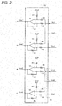
- Fig. 2 is a view illustrating an example of a circuit configuration of the voltage detector 70.
- the voltage detector 70 includes operational amplifiers 72, 74, 76, and 78.
- Each of the operational amplifiers 72, 74, 76, and 78 includes a non-inverting input terminal, an inverting input terminal, and an output terminal.
- the voltage detector 70 also includes a terminal unit 71.
- the terminal unit 71 electrically connects the operational amplifiers 76 and 78 and the first voltage line 250u, the neutral line 250o, and the second voltage line 250w.
- the terminal unit 71 may be detachably attached to the power conditioner 10.
- the operational amplifiers 76 and 78 and the first voltage line 250u, the neutral line 250o, and the second voltage line 250w are electrically connected to each other can be selected according to the installation place of the power conditioner 10 and the distribution panel 260.
- the operational amplifiers 76 and 78 are electrically connected to the first voltage line 250u, the neutral line 250o, and the second voltage line 250w
- the power conditioner 10 and the distribution panel 260 may be installed while the terminal unit 71 is detached from the power conditioner 10.
- at least some elements constituting the voltage detector 70 may be detachably attached to the power conditioner 10.
- a member that is detachably attached to the power conditioner 10 may include at least the terminal unit 71.
- the member may included at least some element constituting the voltage detector 70 in addition to the terminal unit 71.
- the voltage Vo1 is inputted to the non-inverting input terminal of the operational amplifier 72 through a resistor R2.
- a reference voltage Vref is inputted to the non-inverting input terminal of the operational amplifier 72 through a resistor R1.
- the voltage Vu1 is inputted to the inverting input terminal of the operational amplifier 72 through the resistor R2.
- the voltage Vuo1 outputted from the output terminal of the operational amplifier 72 is fed back to the inverting input terminal of the operational amplifier 72 through the resistor R1.
- the voltage Vo1 is input to the non-inverting input terminal of the operational amplifier 74 through the resistor R2.
- the reference voltage Vref is inputted to the non-inverting input terminal of the operational amplifier 74 through a resistor R1.
- the voltage Vw1 is inputted to the inverting input terminal of the operational amplifier 74 through the resistor R2.
- the voltage Vwo1 outputted from the output terminal of the operational amplifier 74 is fed back to the inverting input terminal of the operational amplifier 74 through the resistor R1.
- the voltage Vo2 is inputted to the non-inverting input terminal of the operational amplifier 76 through a resistor R4.
- the reference voltage Vref is inputted to the non-inverting input terminal of the operational amplifier 76 through a resistor R3.
- the voltage Vu2 is inputted to the inverting input terminal of the operational amplifier 76 through the resistor R4.
- the voltage Vuo2 outputted from the output terminal of the operational amplifier 76 is fed back to the inverting input terminal of the operational amplifier 76 through the resistor R3.
- the voltage Vo2 is inputted to the non-inverting input terminal of the operational amplifier 78 through the resistor R4.
- the reference voltage Vref is inputted to the non-inverting input terminal of the operational amplifier 78 through a resistor R3.
- the voltage Vw2 is inputted to the inverting input terminal of the operational amplifier 78 through the resistor R4.
- the voltage Vwo2 outputted from the output terminal of the operational amplifier 78 is fed back to the inverting input terminal of the operational amplifier 78 through the resistor R3.
- the voltage Vu1, the voltage Vo1, the voltage Vw1, the voltage Vu2, the voltage Vo2, and the voltage Vw2 are directly inputted to the operational amplifier 72, the operational amplifier 74, the operational amplifier 76, and the operational amplifier 78.
- the voltage Vu1, the voltage Vo1, the voltage Vw1, the voltage Vu2, the voltage Vo2, and the voltage Vw2 may be inputted to the operational amplifier 72, the operational amplifier 74, the operational amplifier 76, and the operational amplifier 78 alter stepped down by a transformer. Therefore, the operational amplifier 72, the operational amplifier 74, the operational amplifier 76, and the operational amplifier 78 can be insulated from the first voltage line 250u, the neutral line 250o, and the second voltage line 250w.
- Fig. 3 illustrates an example of a functional block of the control device 100 of the present embodiment.
- the control device 100 includes a first voltage acquisition unit 102, a second voltage acquisition unit 104, a selector 106, and a reduction controller 108.
- the first voltage acquisition unit 102 acquires the voltages Vuo1 and Vwo1 corresponding to the line voltages (Vu1 - Vo1) and (Vw1 - Vo1) at the power conditioner 10, which is interconnected with the system power supply 300, on the side of the system power supply 300 through the operational amplifiers 72 and 74.
- the selector 106 selects one of the operational amplifiers 72 and 74 and the operational amplifiers 76 and 78 as the voltage detector used to determine whether the voltage-rise reduction control is performed.
- the reduction controller 108 performs the reduction control in order to reduce the rise of the output voltage at the power conditioner 10 when the voltage Vuo1, the voltage Vwo1, the voltage Vuo2, or the voltage Vwo2 is greater than or equal to a threshold voltage.
- the voltage Vuo1, the voltage Vwo1, the voltage Vuo2, or the voltage Vwo2 is acquired by one of the operational amplifiers 72 and 74 and the operational amplifiers 76 and 78, and the operational amplifiers 72 and 74 or the operational amplifiers 76 and 78 are selected by the selector 106.
- the reduction controller 108 controls the reactive power or the active power, which is outputted from the power conditioner 10, by controlling the turn-on and -off of each switch included in the inverter 40, thereby performing the reduction control.
- the selector 106 may select one of the operational amplifiers 72 and 74 and the operational amplifiers 76 and 78 based on whether the voltage detector 70 is electrically connected to the first voltage line 250u, the neutral line 250o, and the second voltage line 250w.
- the selector 106 may select the operational amplifiers 76 and 78 when the voltage detector 70 is electrically connected to the first voltage line 250u, the neutral line 250o, and the second voltage line 250w.
- the selector 106 may select the operational amplifiers 76 and 78 when the voltage detector 70 is not electrically connected to the first voltage line 250u, the neutral line 250o, and the second voltage line 250w.
- the selector 106 may select the operational amplifiers 76 and 78 in the case where the voltage Vuo2 or the voltage Vwo2 satisfies a predetermined condition, and the selector 106 may select the operational amplifiers 72 and 74 in the case where the voltage Vuo2 or the voltage Vwo2 does not satisfy the predetermined condition.
- the voltage Vuo2 or the voltage Vwo2 which is outputted from the operational amplifiers 76 and 78, falls within a relatively narrow range based on the reference voltage Vref.
- the selector 106 may determine that the voltage detector 70 is not electrically connected to the first voltage line 250u, the neutral line 250o, and the second voltage line 250w, and the selector 106 may select the operational amplifiers 72 and 74.
- the selector 106 may determine that the voltage detector 70 is electrically connected to the first voltage line 250u, the neutral line 250o, and the second voltage line 250w, and the selector 106 may select the operational amplifiers 76 and 78.
- the predetermined voltage range may be a voltage range fixed around the reference voltage Vref.
- the voltage detector 70 is electrically connected to the first voltage line 250u, the neutral line 250o, and the second voltage line 250w, the voltage drop caused by the impedances of the resistor Ru1 and the resistor Rw1 increases with increasing current Io outputted from the inverter 40.
- the selector 106 may determine that the voltage detector 70 is electrically connected to the first voltage line 250u, the neutral line 250o, and the second voltage line 250w, and the selector 106 may select the operational amplifiers 76 and 78.
- the selector 106 may determine that the voltage detector 70 is not electrically connected to the first voltage line 250u, the neutral line 250o, and the second voltage line 250w, and the selector 106 may select the operational amplifiers 72 and 74.
- the selector 106 may select the operational amplifiers 76 and 78 when the current Io and the voltage Vuo2 or the voltage Vwo2 satisfy an inversely proportional relationship.
- the selector 106 may select the operational amplifiers 72 and 74 when the current Io and the voltage Vuo2 or the voltage Vwo2 do not satisfy the inversely proportional relationship.
- the selector 106 may receive a selection signal through a switchable member, such as a dip switch, which can manually be switched.
- a switchable member such as a dip switch
- the worker may select the voltage detector, which is used to determine whether the voltage-rise reduction control is performed, in consideration of the positional relationship between the power conditioner 10 and the distribution panel 260.
- the worker may transmit the selection signal indicating the operational amplifiers 72 and 74 or the operational amplifiers 76 and 78 to the selector 106 through the dip switch.
- the worker may transmit the selection signal indicating the operational amplifiers 72 and 74 or the operational amplifiers 76 and 78 to the selector 106 using a setter such as a personal computer.
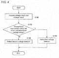
- Fig. 4 is a flowchart illustrating an example of a voltage detector selection procedure, which is performed by the selector 106 and used to determine whether the voltage-rise reduction control is performed.
- the second voltage acquisition unit 104 acquires the voltage Vuo2 and the voltage Vwo2 through the operational amplifiers 76 and 78 (S100).
- the selector 106 determines whether the voltage Vuo2 and the voltage Vwo2 fall within the predetermined voltage range (S102).
- the selector 106 selects the operational amplifiers 72 and 74 as the first voltage detector (S104). On the other hand, when the voltage Vuo2 and the voltage Vwo2 fall within the predetermined voltage range, the selector 106 selects the operational amplifiers 76 and 78 as the second voltage detector (S106).
- one of the voltage at the power conditioner 10 on the side of the system power supply 300 and the voltage at the distribution panel 260 on the side of the power conditioner 10 can be selected as the voltage used to determine whether the voltage-rise reduction control is performed. Therefore, for example, the detection point of the voltage used to determine whether the voltage-rise reduction control is performed can be changed according to the installation places of the power conditioner 10 and the distribution panel 260.
- Each unit included in the control device 100 of the present embodiment may be constructed by installing a program, which is recorded in a computer-readable recording medium to perform various pieces of processing related to the voltage-rise reduction control of the power conditioner 10, and by causing the computer to execute the program. That is, the computer acts as each unit included in the control device 100 by causing the computer to execute the program, which performs various pieces of processing related to the voltage-rise reduction control of the power conditioner 10, whereby the control device 100 may be constructed.
Landscapes
- Engineering & Computer Science (AREA)
- Electromagnetism (AREA)
- Sustainable Development (AREA)
- Sustainable Energy (AREA)
- Power Engineering (AREA)
- Physics & Mathematics (AREA)
- Life Sciences & Earth Sciences (AREA)
- General Physics & Mathematics (AREA)
- Radar, Positioning & Navigation (AREA)
- Automation & Control Theory (AREA)
- Inverter Devices (AREA)
- Supply And Distribution Of Alternating Current (AREA)
- Dc-Dc Converters (AREA)
Abstract
Description
- The present invention relates to a control device, a power conditioner, a distributed power supply system, a program, and a control method.
- Japanese Unexamined Patent Publication No.
2003-9399 - Like Japanese Unexamined Patent Publication No.
2003-9399 - In accordance with a first aspect of the present invention, a control device includes: a first voltage acquisition unit configured to acquire a first voltage from a first voltage detector, the first voltage detector detecting the first voltage corresponding to a line voltage at a power conditioner on a side of a system power supply, the power conditioner being interconnected with the system power supply; a second voltage acquisition unit configured to acquire a second voltage from a second voltage detector, the second voltage detector detecting the second voltage corresponding to a line voltage at a load on the side of the power conditioner, the load being provided between the power conditioner and the system power supply; a selector configured to select one of the first voltage detector and the second voltage detector; and a reduction controller configured to perform reduction control in order to reduce an output voltage at the power conditioner based on the first voltage or the second voltage, the first voltage or the second voltage being acquired from one of the first voltage detector and the second voltage detector, the first voltage detector and the second voltage detector being selected by the selector.
- In the control device, the selector may select the second voltage detector when the second voltage satisfies a predetermined condition, and the selector may select the first voltage detector when the second voltage does not satisfy the predetermined condition.
- In the control device, the selector may select the second voltage detector when a condition that the second voltage falls within a predetermined voltage range is satisfied, and the selector may select the first voltage detector when the condition that the second voltage falls within the predetermined voltage range is not satisfied.
- In the control device, the second voltage detector may include: a non-inverting input terminal to which a voltage at a neutral line of the load on the side of the power conditioner and a reference voltage are inputted; an inverting input terminal to which a voltage at a voltage line of the load on the side of the power conditioner is inputted; and an output terminal from which a potential difference between the voltage inputted from the non-inverting input terminal and the voltage imputed from the inverting input terminal is outputted as the second voltage, and the voltage range may previously be fixed based on the reference voltage.
- In the control device, the selector may select the second voltage detector when a current outputted from the power conditioner and the second voltage satisfy an inversely proportional relationship, and the selector may select the first voltage detector when the current output from the power conditioner and the second voltage do not satisfy the inversely proportional relationship.
- In accordance with a second aspect of the present invention, a power conditioner includes: the control device; the first voltage detector; the second voltage detector; and an inverter configured to interconnect power from a distributed power supply with power from the system power supply. In the power conditioner, the reduction controller performs the reduction control by controlling an output of the inverter.
- The power conditioner may further include a member that is provided while detachably attached to the power conditioner. In the power conditioner, the member may include a terminal unit configured to connect the second voltage detector and a voltage line and a neutral line of the load on the side of the power conditioner.
- In accordance with a third aspect of the present invention, a distributed power supply system includes: the power conditioner; and the distributed power supply.
- In accordance with a fourth aspect of the present invention, a program is configured to cause a computer to act as the control device.
- In accordance with a fifth aspect of the present invention, a control method includes: a step of acquiring a first voltage from a first voltage detector, the first voltage detector detecting the first voltage corresponding to a line voltage at a power conditioner on a side of a system power supply, the power conditioner being interconnected with the system power supply; a step of acquiring a second voltage from a second voltage detector, the second voltage detector detecting the second voltage corresponding to a line voltage at a load on the side of the power conditioner, the load being provided between the power conditioner and the system power supply; a step of selecting one of the first voltage detector and the second voltage detector; and a step of performing reduction control in order to reduce an output voltage at the power conditioner based on the first voltage or the second voltage, the first voltage or the second voltage being acquired from one of the first voltage detector and the second voltage detector, the first voltage detector and the second voltage detector being selected in the selecting step.
- All the features necessary for the present invention are not described in the summary of the present invention. A sub-combination of a feature group is also included in the present invention.
-
-
Fig. 1 is a system configuration diagram illustrating an example of an entire configuration of a photovoltaic system according to an embodiment; -
Fig. 2 is a view illustrating an example of a circuit configuration of a voltage detector; -
Fig. 3 is a view illustrating a functional block of a control device; and -
Fig. 4 is a flowchart illustrating an example of a voltage detector selection procedure used to determine whether voltage-rise reduction control is performed. - Hereinafter, an embodiment of the present invention will be described. However, the present invention according to the claims is not limited to the embodiment. All combinations of features described in the embodiment are not necessary for the means for solving the problem.
-
Fig. 1 is a system configuration diagram illustrating an example of an entire configuration of a photovoltaic system of the embodiment. The photovoltaic system includes aphotovoltaic array 200 and apower conditioner 10. A plurality of photovoltaic strings in which a plurality of photovoltaic modules are connected in series are connected in parallel in thephotovoltaic array 200. Thephotovoltaic array 200 is an example of the distributed power supply. For example, a gas engine, a gas turbine, a micro gas turbine, a fuel cell, a wind generation device, an electric automobile, and an electricity storage system may be used as the distributed power supply. - The
power conditioner 10 boosts a DC voltage outputted from thephotovoltaic array 200, converts the boosted DC voltage into an AC voltage, and outputs the AC voltage onto a side of asystem power supply 300. Thepower conditioner 10 includes a capacitor C1, aboost circuit 20, a capacitor C2, aninverter 40, a coil L, a capacitor C3, arelay 50, apower supply 60, avoltage detector 70, and acontrol device 100. - Both ends of the capacitor C1 are electrically connected to a positive electrode terminal and a negative electrode terminal of the
photovoltaic array 200, respectively, and the capacitor C1 smoothes the DC voltage outputted from thephotovoltaic array 200. Theboost circuit 20 may be what is called a chopper switching regulator. Theboost circuit 20 boosts the voltage outputted from thephotovoltaic array 200. For example, theboost circuit 20 may be constructed by an insulation type boost circuit, such as a half-bridge boost circuit and a full-bridge boost circuit, which has a transformer winding. - The capacitor C2 smoothes the DC voltage outputted from the
boost circuit 20. Theinverter 40 includes a switch, and converts the DC voltage outputted from theboost circuit 20 into the AC voltage by turning on and off the switch to output to thesystem power supply 300. For example, theinverter 40 may be constructed by a single-phase full-bridge PWM inverter including four bridge-connected semiconductor switches. In one pair out of the four semiconductor switches, the semiconductor switches are connected in series. In the other pair out of the four semiconductor switches, the semiconductor switches are connected in series. The other pair of semiconductor switches is connected in parallel to the one pair out of semiconductor switches. - The coil L and the capacitor C3 are provided between the
inverter 40 and thesystem power supply 300. The coil L and the capacitor C3 remove a noise from the AC voltage outputted from theinverter 40. Therelay 50 is provided between the capacitor C3 and thesystem power supply 300. Therelay 50 switches whether theinverter 40 and thesystem power supply 300 are electrically disconnected from each other. Thepower conditioner 10 and thesystem power supply 300 are electrically connected to each other by turning on therelay 50, and thepower conditioner 10 and thesystem power supply 300 are electrically disconnected from each other by turning off therelay 50. - The
power conditioner 10 includesoutput terminals output terminals first voltage line 250u through which a U-phase current passes is connected to theoutput terminal 52. A neutral line 250o through which an O-phrase current passes is connected to theoutput terminal 54. Asecond voltage line 250w through which a W-phase current passes is connected to theoutput terminal 56. - The
first voltage line 250u includes a resistor Ru1 and a resistor Ru2. The neutral line 250o includes a resistor Ro1 and a resistor Ro2. Thesecond voltage line 250w includes a resistor Rw1 and a resistor Rw2. Adistribution panel 260 is provided among the resistor Ru1, the resistor Ro1, and the resistor Rw1 and the resistor Ru2, the resistor Ro2, and the resistor Rw2 on thefirst voltage line 250u, the neutral line 250o, and thesecond voltage line 250w. Awattmeter 270 is provided on the side of thesystem power supply 300 of the resistor Ru2, the resistor Ro2, and the resistor Rw2 on thefirst voltage line 250u, the neutral line 250o, and thesecond voltage line 250w. Thedistribution panel 260 and thewattmeter 270 are examples of the load. The resistor Ru1, the resistor Ro1, and the resistor Rw1 indicate resistances of wirings connecting thepower conditioner 10 and thedistribution panel 260. The resistor Ru2, the resistor Ro2, and the resistor Rw1 indicate resistances of wirings connecting thedistribution panel 260 and thewattmeter 270. - For example, the
power supply 60 is constructed by a power supply IC chip. Thepower supply 60 is connected onto an output side of theboost circuit 20. Thepower supply 60 generates power, which indicates a predetermined voltage supplied to thecontrol device 100, from the DC voltage taken out from theboost circuit 20, and thepower supply 60 supplies the generated power to thecontrol device 100. Thepower supply 60 may directly use the power from thesystem power supply 300 to generate the power supplied to thecontrol device 100. - In order to obtain the maximum power from the
photovoltaic array 200, thecontrol device 100 controls the switching operations of theboost circuit 20 and theinverter 40, boosts the DC voltage outputted from thephotovoltaic array 200, converts the boosted DC voltage into the AC voltage, and outputs the AC voltage onto the side of thesystem power supply 300. - The
power conditioner 10 also includesvoltage sensors current sensors voltage sensor 12 detects a voltage V1 corresponding to a potential difference between both the ends of thephotovoltaic array 200. Thevoltage sensor 16 detects a voltage V2 corresponding to a potential difference between both the ends on the output side of theboost circuit 20. Thecurrent sensor 14 detects a current I1, which is outputted from thephotovoltaic array 200 and passes onto the input side of theboost circuit 20. Thecurrent sensor 18 detects a current I2 outputted from theboost circuit 20. Thecurrent sensor 19 detects a current Io outputted from theinverter 40. - A U-phase voltage Vu1, an O-phase voltage Vo1, and a W-phase voltage Vw1 at the
power conditioner 10 on the side of thesystem power supply 300 are inputted to thevoltage detector 70. That is, the voltage Vu1, the voltage Vo1, and the voltage Vw1 at theoutput terminals voltage detector 70. A U-phase voltage Vu2, an O-phase voltage Vo2, and a W-phase voltage Vw2 at thedistribution panel 260 on the power conditioner side are also inputted to thevoltage detector 70. That is, the voltage Vu2, the voltage Vo2, and the voltage Vw2 atterminals distribution panel 260 and connected to thepower conditioner 10, are also inputted to thevoltage detector 70. - The
voltage detector 70 detects a voltage Vuo1 corresponding to a line voltage (Vu1 - Vo1) indicating the potential difference between the voltage Vu1 and the voltage Vo1 and a voltage Vwo1 corresponding to a line voltage (Vw1 - Vo1) indicating the potential difference between the voltage Vw1 and the voltage Vo1. Thevoltage detector 70 detects a voltage Vuo2 corresponding to a line voltage (Vu2 - Vo2) indicating the potential difference between the voltage Vu2 and the voltage Vo2. Thevoltage detector 70 detects a voltage Vwo2 corresponding to a line voltage (Vw2 - Vo2) indicating the potential difference between the voltage Vw2 and the voltage Vo2. - It is necessary for the
power conditioner 10 having the above configuration to control the voltage such that the voltage outputted onto the side of thesystem power supply 300 is less than an upper-limit voltage. For example, thepower conditioner 10 may control the output of thepower conditioner 10 such that the voltage indicating the potential difference between theoutput terminal 52 and theoutput terminal 54 and the voltage indicating the potential difference between theoutput terminal 56 and theoutput terminal 54 are less than the upper-limit voltage. Thepower conditioner 10 may control the output of thepower conditioner 10 such that the voltage indicating the potential difference between the terminal 262 and the terminal 264, which are included in thedistribution panel 260, and the voltage indicating the potential difference between the terminal 266 and the terminal 264, which are included in thedistribution panel 260, are less than the upper-limit voltage. Alternatively, thepower conditioner 10 may control the output of thepower conditioner 10 such that the voltage indicating the potential difference between a terminal 272 and a terminal 274, which are included in thewattmeter 270 and connected to thedistribution panel 260, and the voltage indicating the potential difference between a terminal 276 and the terminal 274, which are included in thewattmeter 270 and connected to thedistribution panel 260, are less than the upper-limit voltage. As used herein, the upper-limit voltage means a value that is fixed based on an upper limit defined by a grid-interconnection code. - The
control device 100 determines whether reduction control is performed in order to reduce a rise of the output voltage at thepower conditioner 10 based on the voltage detected by thevoltage detector 70. When determining that the reduction control is performed, for example, thecontrol device 100 increases reactive power supplied onto the side of thesystem power supply 300 by adjusting a phase difference between a current phase and a voltage phase, which are outputted from theinverter 40. Alternatively, thecontrol device 100 decreases active power by adjusting a current amplitude outputted from theinverter 40. Therefore, thecontrol device 100 performs the control until the voltage outputted from thepower conditioner 10 is less than the upper-limit voltage. - The
control device 100 determines whether the voltage-rise reduction control is performed in order to reduce the rise of the output voltage at thepower conditioner 10 based on at least one of the voltage Vuo1 and the voltage Vwo1, which are detected by thevoltage detector 70, or at least one of the voltage Vuo2 and the voltage Vwo2, which are detected by thevoltage detector 70. - In the case where the
control device 100 determines whether the voltage-rise reduction control is performed based on at least one of the line voltage (Vu2 - Vo2) indicating the potential difference between the terminal 262 and theterminal 264 of thedistribution panel 260 and the line voltage (Vw2-Vo2) indicating the potential difference between the terminal 262 and theterminal 264 of thedistribution panel 260, thecontrol device 100 can determine whether the voltage-rise reduction control is performed in consideration of a voltage drop caused by the resistor Ru1, the resistor Ro1, and the resistor Rw1 on thefirst voltage line 250u, the neutral line 250o, and thesecond voltage line 250w. - For example, the
voltage detector 70 may electrically be connected to thefirst voltage line 250u, the neutral line 250o, and thesecond voltage line 250w of thewattmeter 270 on the power conditioner side. Thevoltage detector 70 may be connected to theterminals wattmeter 270. In this case, thecontrol device 100 can determine whether the voltage-rise reduction control is performed based on at least one of the line voltages (Vu2 - Vo2) and (Vw2 - Vo2), which are derived in consideration of the voltage drop caused by the resistor Ru1, the resistor Ro1, the resistor Rw1, the resistor Ru2, the resistor Ro2, and the resistor Rw2. - However, occasionally an electric cable that electrically connects the
voltage detector 70 and thefirst voltage line 250u, the neutral line 250o, and thesecond voltage line 250w is hardly provided depending on installation places of thepower conditioner 10 and thedistribution panel 260. For example, in the case where the installation places of thepower conditioner 10 and thedistribution panel 260 are close to each other, occasionally the resistor Ru1, the resistor Ro1, and the resistor Rw1 have a little influence on the voltage drop because of small impedances of the resistor Ru1, the resistor Ro1, and the resistor Rw1. Occasionally it is not suitable to provide the electric cable that electrically connects thevoltage detector 70 and thefirst voltage line 250u, the neutral line 250o, and thesecond voltage line 250w. - Therefore, in the present embodiment, the
control device 100 determines whether the reduction control is performed in order to reduce the rise of the output voltage at thepower conditioner 10 based on at least one of the voltage Vuo1 and the voltage Vwo1, which are detected by thevoltage detector 70, or at least one of the voltage Vuo2 and the voltage Vwo2, which are detected by thevoltage detector 70. That is, one of the voltage at thepower conditioner 10 on the side of thesystem power supply 300 and the voltage at thedistribution panel 260 on the side of thepower conditioner 10 can be selected as the voltage used to determine whether the voltage-rise reduction control is performed. - For example, even if the electric cable that electrically connects the
voltage detector 70 and thefirst voltage line 250u, the neutral line 250o, and thesecond voltage line 250w is hardly provided, whether the voltage-rise reduction control is performed can be determined. In the case where the voltage drop is not generated too much between thepower conditioner 10 and thedistribution panel 260 because of a short distance between thepower conditioner 10 and thedistribution panel 260, whether the voltage-rise reduction control is performed can be determined even if the new electric cable is not provided. Therefore, an installation cost can be prevented from increasing beyond necessity. - According to the present embodiment, for example, a detection point of the voltage used to determine whether the voltage-rise reduction control is performed can be changed according to the installation places of the
power conditioner 10 and thedistribution panel 260. -
Fig. 2 is a view illustrating an example of a circuit configuration of thevoltage detector 70. Thevoltage detector 70 includesoperational amplifiers operational amplifiers - The
voltage detector 70 also includes aterminal unit 71. Theterminal unit 71 electrically connects theoperational amplifiers first voltage line 250u, the neutral line 250o, and thesecond voltage line 250w. Theterminal unit 71 may be detachably attached to thepower conditioner 10. - As described above, whether the
operational amplifiers first voltage line 250u, the neutral line 250o, and thesecond voltage line 250w are electrically connected to each other can be selected according to the installation place of thepower conditioner 10 and thedistribution panel 260. In the case where theoperational amplifiers first voltage line 250u, the neutral line 250o, and thesecond voltage line 250w, because theterminal unit 71 is unnecessary, thepower conditioner 10 and thedistribution panel 260 may be installed while theterminal unit 71 is detached from thepower conditioner 10. In addition to the connection terminal, at least some elements constituting thevoltage detector 70 may be detachably attached to thepower conditioner 10. A member that is detachably attached to thepower conditioner 10 may include at least theterminal unit 71. The member may included at least some element constituting thevoltage detector 70 in addition to theterminal unit 71. - The voltage Vo1 is inputted to the non-inverting input terminal of the
operational amplifier 72 through a resistor R2. A reference voltage Vref is inputted to the non-inverting input terminal of theoperational amplifier 72 through a resistor R1. The voltage Vu1 is inputted to the inverting input terminal of theoperational amplifier 72 through the resistor R2. - The voltage Vuo1 outputted from the output terminal of the
operational amplifier 72 is fed back to the inverting input terminal of theoperational amplifier 72 through the resistor R1. - The voltage Vo1 is input to the non-inverting input terminal of the
operational amplifier 74 through the resistor R2. The reference voltage Vref is inputted to the non-inverting input terminal of theoperational amplifier 74 through a resistor R1. The voltage Vw1 is inputted to the inverting input terminal of theoperational amplifier 74 through the resistor R2. - The voltage Vwo1 outputted from the output terminal of the
operational amplifier 74 is fed back to the inverting input terminal of theoperational amplifier 74 through the resistor R1. - The voltage Vo2 is inputted to the non-inverting input terminal of the
operational amplifier 76 through a resistor R4. The reference voltage Vref is inputted to the non-inverting input terminal of theoperational amplifier 76 through a resistor R3. The voltage Vu2 is inputted to the inverting input terminal of theoperational amplifier 76 through the resistor R4. - The voltage Vuo2 outputted from the output terminal of the
operational amplifier 76 is fed back to the inverting input terminal of theoperational amplifier 76 through the resistor R3. - The voltage Vo2 is inputted to the non-inverting input terminal of the
operational amplifier 78 through the resistor R4. The reference voltage Vref is inputted to the non-inverting input terminal of theoperational amplifier 78 through a resistor R3. The voltage Vw2 is inputted to the inverting input terminal of theoperational amplifier 78 through the resistor R4. - The voltage Vwo2 outputted from the output terminal of the
operational amplifier 78 is fed back to the inverting input terminal of theoperational amplifier 78 through the resistor R3. - At this point, the voltages Vuo1, Vwo1, Vuo2, and Vwo2 can be expressed by equations (1) to (4).


- Therefore, the
operational amplifier 72 outputs the voltage Vuo1 corresponding to the potential difference between the voltage Vu1 at thefirst voltage line 250u and the voltage Vo1 at the neutral line 250o of thepower conditioner 10 on the side of thesystem power supply 300. Theoperational amplifier 74 outputs the voltage Vwo1 corresponding to the potential difference between the voltage Vw1 at thesecond voltage line 250w and the voltage Vo1 at the neutral line 250o of thepower conditioner 10 on the side of thesystem power supply 300. Theoperational amplifier 76 outputs the voltage Vuo2 corresponding to the potential difference between the voltage Vu2 at thefirst voltage line 250u and the voltage Vo2 at the neutral line 250o of thedistribution panel 260 on the side of thepower conditioner 10. Theoperational amplifier 78 outputs the voltage Vwo2 corresponding to the potential difference between the voltage Vw2 at thesecond voltage line 250w and the voltage Vo2 at the neutral line 250o of thedistribution panel 260 on the side of thepower conditioner 10. - In the present embodiment, the voltage Vu1, the voltage Vo1, the voltage Vw1, the voltage Vu2, the voltage Vo2, and the voltage Vw2 are directly inputted to the
operational amplifier 72, theoperational amplifier 74, theoperational amplifier 76, and theoperational amplifier 78. However, the voltage Vu1, the voltage Vo1, the voltage Vw1, the voltage Vu2, the voltage Vo2, and the voltage Vw2 may be inputted to theoperational amplifier 72, theoperational amplifier 74, theoperational amplifier 76, and theoperational amplifier 78 alter stepped down by a transformer. Therefore, theoperational amplifier 72, theoperational amplifier 74, theoperational amplifier 76, and theoperational amplifier 78 can be insulated from thefirst voltage line 250u, the neutral line 250o, and thesecond voltage line 250w. -
Fig. 3 illustrates an example of a functional block of thecontrol device 100 of the present embodiment. Thecontrol device 100 includes a firstvoltage acquisition unit 102, a secondvoltage acquisition unit 104, aselector 106, and areduction controller 108. - The first
voltage acquisition unit 102 acquires the voltages Vuo1 and Vwo1 corresponding to the line voltages (Vu1 - Vo1) and (Vw1 - Vo1) at thepower conditioner 10, which is interconnected with thesystem power supply 300, on the side of thesystem power supply 300 through theoperational amplifiers - The second
voltage acquisition unit 104 acquires the voltages Vuo2 and Vwo2 corresponding to the line voltages (Vu2 - Vo2) and (Vw2 - Vo2) at thedistribution panel 260 on the side of thepower conditioner 10 through theoperational amplifiers - The
selector 106 selects one of theoperational amplifiers operational amplifiers - The
reduction controller 108 performs the reduction control in order to reduce the rise of the output voltage at thepower conditioner 10 when the voltage Vuo1, the voltage Vwo1, the voltage Vuo2, or the voltage Vwo2 is greater than or equal to a threshold voltage. The voltage Vuo1, the voltage Vwo1, the voltage Vuo2, or the voltage Vwo2 is acquired by one of theoperational amplifiers operational amplifiers operational amplifiers operational amplifiers selector 106. For example, thereduction controller 108 controls the reactive power or the active power, which is outputted from thepower conditioner 10, by controlling the turn-on and -off of each switch included in theinverter 40, thereby performing the reduction control. - The
selector 106 may select one of theoperational amplifiers operational amplifiers voltage detector 70 is electrically connected to thefirst voltage line 250u, the neutral line 250o, and thesecond voltage line 250w. Theselector 106 may select theoperational amplifiers voltage detector 70 is electrically connected to thefirst voltage line 250u, the neutral line 250o, and thesecond voltage line 250w. Theselector 106 may select theoperational amplifiers voltage detector 70 is not electrically connected to thefirst voltage line 250u, the neutral line 250o, and thesecond voltage line 250w. - The
selector 106 may select theoperational amplifiers selector 106 may select theoperational amplifiers - In the case where the
voltage detector 70 is not electrically connected to thefirst voltage line 250u, the neutral line 250o, and thesecond voltage line 250w, the voltage Vuo2 or the voltage Vwo2, which is outputted from theoperational amplifiers - Therefore, in the case where the voltage Vuo2 or the voltage Vwo2 falls within the predetermined range based on the reference voltage Vref, the
selector 106 may determine that thevoltage detector 70 is not electrically connected to thefirst voltage line 250u, the neutral line 250o, and thesecond voltage line 250w, and theselector 106 may select theoperational amplifiers selector 106 may determine that thevoltage detector 70 is electrically connected to thefirst voltage line 250u, the neutral line 250o, and thesecond voltage line 250w, and theselector 106 may select theoperational amplifiers - In the case where the
voltage detector 70 is electrically connected to thefirst voltage line 250u, the neutral line 250o, and thesecond voltage line 250w, the voltage drop caused by the impedances of the resistor Ru1 and the resistor Rw1 increases with increasing current Io outputted from theinverter 40. - Therefore, in the case where the voltage Vuo2 or the voltage Vwo2 decreases with increasing current Io detected by the
current sensor 19, theselector 106 may determine that thevoltage detector 70 is electrically connected to thefirst voltage line 250u, the neutral line 250o, and thesecond voltage line 250w, and theselector 106 may select theoperational amplifiers current sensor 19, theselector 106 may determine that thevoltage detector 70 is not electrically connected to thefirst voltage line 250u, the neutral line 250o, and thesecond voltage line 250w, and theselector 106 may select theoperational amplifiers selector 106 may select theoperational amplifiers selector 106 may select theoperational amplifiers - The
selector 106 may receive a selection signal through a switchable member, such as a dip switch, which can manually be switched. For example, in the case where a worker installs thepower conditioner 10, the worker may select the voltage detector, which is used to determine whether the voltage-rise reduction control is performed, in consideration of the positional relationship between thepower conditioner 10 and thedistribution panel 260. The worker may transmit the selection signal indicating theoperational amplifiers operational amplifiers selector 106 through the dip switch. The worker may transmit the selection signal indicating theoperational amplifiers operational amplifiers selector 106 using a setter such as a personal computer. -
Fig. 4 is a flowchart illustrating an example of a voltage detector selection procedure, which is performed by theselector 106 and used to determine whether the voltage-rise reduction control is performed. - When the
power conditioner 10 is started up, the secondvoltage acquisition unit 104 acquires the voltage Vuo2 and the voltage Vwo2 through theoperational amplifiers 76 and 78 (S100). Theselector 106 determines whether the voltage Vuo2 and the voltage Vwo2 fall within the predetermined voltage range (S102). - When at least one of the voltage Vuo2 and the voltage Vwo2 does not fall within the predetermined voltage range, the
selector 106 selects theoperational amplifiers selector 106 selects theoperational amplifiers - As described above, according to the present embodiment, one of the voltage at the
power conditioner 10 on the side of thesystem power supply 300 and the voltage at thedistribution panel 260 on the side of thepower conditioner 10 can be selected as the voltage used to determine whether the voltage-rise reduction control is performed. Therefore, for example, the detection point of the voltage used to determine whether the voltage-rise reduction control is performed can be changed according to the installation places of thepower conditioner 10 and thedistribution panel 260. - Each unit included in the
control device 100 of the present embodiment may be constructed by installing a program, which is recorded in a computer-readable recording medium to perform various pieces of processing related to the voltage-rise reduction control of thepower conditioner 10, and by causing the computer to execute the program. That is, the computer acts as each unit included in thecontrol device 100 by causing the computer to execute the program, which performs various pieces of processing related to the voltage-rise reduction control of thepower conditioner 10, whereby thecontrol device 100 may be constructed. - The computer includes a CPU, various memories such as a ROM, a RAM, and an EEPROM (registered trademark), a communication bus, and an interface, and the CPU reads and executes sequentially the processing program previously stored in the ROM as firmware, whereby the computer acts as the
control device 100. - Although the embodiment of the present invention is described above, the technical scope of the present invention is not limited to the scope of the embodiment. It is clear for those skilled in the art that various changes and modifications can be made in the present invention. It is clear from the claims that the changes and modifications are also included in the technical scope of the present invention.
- In the performance sequence of pieces of processing such as the operations, the procedures, the steps, and the stages in the device, the system, the program, and the method in the claims, the description, and the drawings, "before" or "prior to" is not described unless otherwise noted, and it is noted that the pieces of processing are performed in any performance sequence as long as the output of the preceding processing is used in the subsequent processing. In the operation flow of the claims, the description, and the drawings, for the sake of convenience, it is not always necessary that the pieces of processing be performed in this order even if "at first" or "then" is used.
Claims (10)
- A control device (100) comprising: a first voltage acquisition unit (102) configured to acquire a first voltage from a first voltage detector, the first voltage detector detecting the first voltage corresponding to a line voltage at a power conditioner (10) on a side of a system power supply (300), the power conditioner being interconnected with the system power supply;
a second voltage acquisition unit (104) configured to acquire a second voltage from a second voltage detector, the second voltage detector detecting the second voltage corresponding to a line voltage at a load (260, 270) on the side of the power conditioner, the load being provided between the power conditioner and the system power supply;
a selector (106) configured to select one of the first voltage detector and the second voltage detector; and
a reduction controller (108) configured to perform reduction control in order to reduce an output voltage at the power conditioner based on the first voltage or the second voltage, the first voltage or the second voltage being acquired from one of the first voltage detector and the second voltage detector, the first voltage detector and the second voltage detector being selected by the selector. - The control device (100) according to claim 1, wherein the selector (106) selects the second voltage detector when the second voltage satisfies a predetermined condition, and the selector selects the first voltage detector when the second voltage does not satisfy the predetermined condition.
- The control device (100) according to claim 1 or 2, wherein the selector (106) selects the second voltage detector when a condition that the second voltage falls within a predetermined voltage range is satisfied, and the selector selects the first voltage detector when the condition that the second voltage falls within the predetermined voltage range is not satisfied.
- The control device (100) according to claim 3, wherein the second voltage detector comprises: a non-inverting input terminal to which a voltage at a neutral line of the load (260,270) on the side of the power conditioner (10) and a reference voltage are inputted; an inverting input terminal to which a voltage at a voltage line of the load on the side of the power conditioner is inputted; and an output terminal from which a potential difference between the voltage inputted from the non-inverting input terminal and the voltage inputted from the inverting input terminal is outputted as the second voltage, and
the voltage range is previously fixed based on the reference voltage. - The control device (100) according to any one of claims 1 to 4, wherein the selector (106) selects the second voltage detector when a current outputted from the power conditioner (10) and the second voltage satisfy an inversely proportional relationship, and the selector selects the first voltage detector when the current outputted from the power conditioner and the second voltage do not satisfy the inversely proportional relationship.
- A power conditioner (10) comprising: the control device (100) according to any one of claims 1 to 5;
the first voltage detector;
the second voltage detector; and
an inverter (40) configured to interconnect power from a distributed power supply with power from the system power supply (300),
wherein the reduction controller (108) performs the reduction control by controlling an output of the inverter. - The power conditioner (10) according to claim 6, further comprising a member that is provided while detachably attached to the power conditioner,
wherein the member comprises a terminal unit (71) configured to connect the second voltage detector and a voltage line and a neutral line of the load on the side of the power conditioner. - A distributed power supply system comprising: the power conditioner according to claim 6 or 7; and
the distributed power supply. - A program configured to cause a computer to act as the control device according to any one of claims 1 to 5.
- A control method comprising: a step of acquiring a first voltage from a first voltage detector, the first voltage detector detecting the first voltage corresponding to a line voltage at a power conditioner (10) on a side of a system power supply (300), the power conditioner being interconnected with the system power supply;
a step of acquiring a second voltage from a second voltage detector, the second voltage detector detecting the second voltage corresponding to a line voltage at a load on the side of the power conditioner, the load being provided between the power conditioner and the system power supply;
a step of selecting one of the first voltage detector and the second voltage detector; and
a step of performing reduction control in order to reduce an output voltage at the power conditioner based on the first voltage or the second voltage, the first voltage or the second voltage being acquired from one of the first voltage detector and the second voltage detector, the first voltage detector and the second voltage detector being selected in the selecting step.
Applications Claiming Priority (1)
| Application Number | Priority Date | Filing Date | Title |
|---|---|---|---|
| JP2013051946A JP6070305B2 (en) | 2013-03-14 | 2013-03-14 | Control device, power conditioner, distributed power supply system, program, and control method |
Publications (2)
| Publication Number | Publication Date |
|---|---|
| EP2778825A2 true EP2778825A2 (en) | 2014-09-17 |
| EP2778825A3 EP2778825A3 (en) | 2014-10-01 |
Family
ID=49999729
Family Applications (1)
| Application Number | Title | Priority Date | Filing Date |
|---|---|---|---|
| EP14150987.7A Withdrawn EP2778825A3 (en) | 2013-03-14 | 2014-01-13 | Control device, power conditioner, distributed power supply system, program, and control method |
Country Status (3)
| Country | Link |
|---|---|
| EP (1) | EP2778825A3 (en) |
| JP (1) | JP6070305B2 (en) |
| CN (1) | CN104052319A (en) |
Citations (2)
| Publication number | Priority date | Publication date | Assignee | Title |
|---|---|---|---|---|
| JP2000023369A (en) * | 1998-06-30 | 2000-01-21 | Matsushita Electric Works Ltd | Distributed power supply equipment |
| JP2003009399A (en) | 2001-06-26 | 2003-01-10 | Matsushita Electric Works Ltd | System interconnected power generating system |
Family Cites Families (8)
| Publication number | Priority date | Publication date | Assignee | Title |
|---|---|---|---|---|
| JPH10210685A (en) * | 1997-01-24 | 1998-08-07 | Toshiba Corp | Control method of grid-connected power converter for fuel cell |
| JPH118937A (en) * | 1997-06-17 | 1999-01-12 | Meidensha Corp | Protective device for system interconnection inverter |
| JP3592595B2 (en) * | 1999-12-07 | 2004-11-24 | 愛知電機株式会社 | Power conversion system for grid connection |
| JP2003009593A (en) * | 2001-04-19 | 2003-01-10 | Ebara Densan Ltd | Gas turbine generator |
| JP5252467B2 (en) * | 2007-04-04 | 2013-07-31 | シャープ株式会社 | Grid interconnection inverter |
| ES2385912T3 (en) * | 2009-04-17 | 2012-08-03 | Sma Solar Technology Ag | Procedure and device to connect a photovoltaic plant to an alternating current network |
| CN102823209B (en) * | 2010-04-09 | 2015-06-10 | 丰田自动车株式会社 | Communication device, communication system, and vehicle |
| US20120075898A1 (en) * | 2010-09-28 | 2012-03-29 | Astec International Limited | Photovoltaic Power Converters and Closed Loop Maximum Power Point Tracking |
-
2013
- 2013-03-14 JP JP2013051946A patent/JP6070305B2/en not_active Expired - Fee Related
-
2014
- 2014-01-13 EP EP14150987.7A patent/EP2778825A3/en not_active Withdrawn
- 2014-01-17 CN CN201410022449.8A patent/CN104052319A/en active Pending
Patent Citations (2)
| Publication number | Priority date | Publication date | Assignee | Title |
|---|---|---|---|---|
| JP2000023369A (en) * | 1998-06-30 | 2000-01-21 | Matsushita Electric Works Ltd | Distributed power supply equipment |
| JP2003009399A (en) | 2001-06-26 | 2003-01-10 | Matsushita Electric Works Ltd | System interconnected power generating system |
Also Published As
| Publication number | Publication date |
|---|---|
| JP6070305B2 (en) | 2017-02-01 |
| CN104052319A (en) | 2014-09-17 |
| EP2778825A3 (en) | 2014-10-01 |
| JP2014180115A (en) | 2014-09-25 |
Similar Documents
| Publication | Publication Date | Title |
|---|---|---|
| JP6337468B2 (en) | Ground fault detection device | |
| US20180083527A1 (en) | Power conversion device and method for controlling power conversion device | |
| JP4719434B2 (en) | Solar cell power generator | |
| JP6213163B2 (en) | Power conditioner, solar cell system, and abnormality determination method | |
| US9906134B1 (en) | Insulation detecting circuit, power converting device and insulation impedance value detecting method | |
| EP3410552B1 (en) | Routing power in a power system | |
| CN102867870A (en) | Solar photovoltaic junction box | |
| EP2824533A2 (en) | Photovoltaic system | |
| JP6191403B2 (en) | Power conditioner, solar cell system, and abnormality determination method | |
| CN104333213A (en) | Protecting method for output overvoltage of PV array, device and system | |
| JP2018207763A (en) | Power converter and reactor abnormality detection method provided in power converter | |
| JP6269299B2 (en) | Ground fault detection device, power supply system, and ground fault detection method | |
| US20260002968A1 (en) | Power converter and detection method thereof | |
| EP2821802A1 (en) | In-vehicle charger | |
| JP6269212B2 (en) | Control device, power conversion device, power supply system, program, and control method | |
| EP2849325A1 (en) | Inverter for photovoltaic modules | |
| EP2778825A2 (en) | Control device, power conditioner, distributed power supply system, program, and control method | |
| EP4266524A1 (en) | Droop control in a dc operated system | |
| CN117310236A (en) | High-voltage AC/DC dry-type load device | |
| JP2016012963A (en) | Power control unit | |
| CN103812328A (en) | Parallel-connection current-sharing circuit for voltage converter | |
| CN116827090B (en) | Switching power supply circuit and control method | |
| JP7418954B2 (en) | Power conditioner and energy storage system | |
| JP2014180113A (en) | Controller, power conditioner, distributed power supply system, program, and control method | |
| JP7045968B2 (en) | Power conditioner and power distribution system |
Legal Events
| Date | Code | Title | Description |
|---|---|---|---|
| PUAL | Search report despatched |
Free format text: ORIGINAL CODE: 0009013 |
|
| PUAI | Public reference made under article 153(3) epc to a published international application that has entered the european phase |
Free format text: ORIGINAL CODE: 0009012 |
|
| 17P | Request for examination filed |
Effective date: 20140113 |
|
| AK | Designated contracting states |
Kind code of ref document: A2 Designated state(s): AL AT BE BG CH CY CZ DE DK EE ES FI FR GB GR HR HU IE IS IT LI LT LU LV MC MK MT NL NO PL PT RO RS SE SI SK SM TR |
|
| AX | Request for extension of the european patent |
Extension state: BA ME |
|
| AK | Designated contracting states |
Kind code of ref document: A3 Designated state(s): AL AT BE BG CH CY CZ DE DK EE ES FI FR GB GR HR HU IE IS IT LI LT LU LV MC MK MT NL NO PL PT RO RS SE SI SK SM TR |
|
| AX | Request for extension of the european patent |
Extension state: BA ME |
|
| RIC1 | Information provided on ipc code assigned before grant |
Ipc: G05F 1/67 20060101AFI20140825BHEP |
|
| R17P | Request for examination filed (corrected) |
Effective date: 20150330 |
|
| RBV | Designated contracting states (corrected) |
Designated state(s): AL AT BE BG CH CY CZ DE DK EE ES FI FR GB GR HR HU IE IS IT LI LT LU LV MC MK MT NL NO PL PT RO RS SE SI SK SM TR |
|
| STAA | Information on the status of an ep patent application or granted ep patent |
Free format text: STATUS: EXAMINATION IS IN PROGRESS |
|
| 17Q | First examination report despatched |
Effective date: 20171031 |
|
| STAA | Information on the status of an ep patent application or granted ep patent |
Free format text: STATUS: THE APPLICATION IS DEEMED TO BE WITHDRAWN |
|
| 18D | Application deemed to be withdrawn |
Effective date: 20180313 |