EP2778738B1 - Aiming optical sight using truncated lenses - Google Patents
Aiming optical sight using truncated lenses Download PDFInfo
- Publication number
- EP2778738B1 EP2778738B1 EP14160129.4A EP14160129A EP2778738B1 EP 2778738 B1 EP2778738 B1 EP 2778738B1 EP 14160129 A EP14160129 A EP 14160129A EP 2778738 B1 EP2778738 B1 EP 2778738B1
- Authority
- EP
- European Patent Office
- Prior art keywords
- eye lens
- optic
- magnifying
- sight
- viewing
- Prior art date
- Legal status (The legal status is an assumption and is not a legal conclusion. Google has not performed a legal analysis and makes no representation as to the accuracy of the status listed.)
- Not-in-force
Links
- 230000003287 optical effect Effects 0.000 title claims description 137
- 238000007789 sealing Methods 0.000 claims description 16
- 238000000034 method Methods 0.000 claims description 13
- 230000011514 reflex Effects 0.000 claims description 9
- 238000004519 manufacturing process Methods 0.000 claims description 7
- 230000000295 complement effect Effects 0.000 claims description 4
- 210000001747 pupil Anatomy 0.000 description 34
- 239000011521 glass Substances 0.000 description 10
- 238000007493 shaping process Methods 0.000 description 4
- 230000004886 head movement Effects 0.000 description 3
- 239000000853 adhesive Substances 0.000 description 2
- 230000001070 adhesive effect Effects 0.000 description 2
- 239000005357 flat glass Substances 0.000 description 2
- 230000008447 perception Effects 0.000 description 2
- 238000000926 separation method Methods 0.000 description 2
- 230000008685 targeting Effects 0.000 description 2
- 238000013459 approach Methods 0.000 description 1
- 230000005494 condensation Effects 0.000 description 1
- 238000009833 condensation Methods 0.000 description 1
- 230000000694 effects Effects 0.000 description 1
- 238000010304 firing Methods 0.000 description 1
- 210000003128 head Anatomy 0.000 description 1
- 230000002452 interceptive effect Effects 0.000 description 1
- 238000005204 segregation Methods 0.000 description 1
Images

Classifications
-
- G—PHYSICS
- G02—OPTICS
- G02B—OPTICAL ELEMENTS, SYSTEMS OR APPARATUS
- G02B23/00—Telescopes, e.g. binoculars; Periscopes; Instruments for viewing the inside of hollow bodies; Viewfinders; Optical aiming or sighting devices
-
- F—MECHANICAL ENGINEERING; LIGHTING; HEATING; WEAPONS; BLASTING
- F41—WEAPONS
- F41G—WEAPON SIGHTS; AIMING
- F41G1/00—Sighting devices
- F41G1/30—Reflecting-sights specially adapted for smallarms or ordnance
-
- F—MECHANICAL ENGINEERING; LIGHTING; HEATING; WEAPONS; BLASTING
- F41—WEAPONS
- F41G—WEAPON SIGHTS; AIMING
- F41G1/00—Sighting devices
- F41G1/38—Telescopic sights specially adapted for smallarms or ordnance; Supports or mountings therefor
-
- G—PHYSICS
- G02—OPTICS
- G02B—OPTICAL ELEMENTS, SYSTEMS OR APPARATUS
- G02B23/00—Telescopes, e.g. binoculars; Periscopes; Instruments for viewing the inside of hollow bodies; Viewfinders; Optical aiming or sighting devices
- G02B23/14—Viewfinders
-
- Y—GENERAL TAGGING OF NEW TECHNOLOGICAL DEVELOPMENTS; GENERAL TAGGING OF CROSS-SECTIONAL TECHNOLOGIES SPANNING OVER SEVERAL SECTIONS OF THE IPC; TECHNICAL SUBJECTS COVERED BY FORMER USPC CROSS-REFERENCE ART COLLECTIONS [XRACs] AND DIGESTS
- Y10—TECHNICAL SUBJECTS COVERED BY FORMER USPC
- Y10T—TECHNICAL SUBJECTS COVERED BY FORMER US CLASSIFICATION
- Y10T29/00—Metal working
- Y10T29/49—Method of mechanical manufacture
- Y10T29/49826—Assembling or joining
Definitions
- Telescopic sights such as rifle scopes, optically magnify distant objects but only provide a narrow field of view. While a distant object may be easier to resolve with a telescopic sight, the narrow field of view may make it difficult to track movement of the object. At close ranges, it is sometimes preferable to provide an alternative aiming point to one eye using a sight having no additional magnification in order to match a view seen by the other, naked eye. In an effort to provide an enlarged view and a view with a wider field of view without swapping scopes, a reflex sight is often mounted to a telescopic sight, so that a user may choose which sight to use when viewing an object according to the circumstances.
- Publication CA 670 887 A discloses an optical aiming-device of particular interest.
- FIG. 1 schematically shows a side cross-section of a combination optical aiming device 100 (depicted as a riflescope in FIG. 1 , though in some embodiments combination optical aiming device 100 may be included in a spotting scope or an archery scope) according to an embodiment of the present disclosure.
- Combination optical aiming device 100 includes a non-magnifying sight 102 and a magnifying sight 104 for viewing differently magnified images of a distant object from a common viewing plane or position.
- non-magnifying sight 102 and magnifying sight 104 are shown mounted within a common housing 106.
- Magnifying sight 104 is a telescope that allows a user to view a magnified, or enlarged, image of a distant object at an eyepoint 108. The image is viewable via an exit pupil at a location behind the sight, preferably at eyepoint 108.
- Magnifying sight 104 includes an eyepiece 110 that may include one or more eye lenses.
- Magnifying sight 104 also includes an objective 112 that may include one or more objective lenses and/or reflectors. Eyepiece 110 and objective 112 are positioned at opposite ends of the sight in the example shown in FIG. 1 .
- objective 112 gathers light from the distant object and produces an inverted image of the object at front focal plane 114, positioned behind objective 112.
- An erector system 116 rectifies the inverted image, producing an erect image of the object at a rear focal plane 118 positioned behind front focal plane 114 and erector system 116.
- Erector system 116 may include one or more lenses or other optical elements (e.g., reflectors and/or prisms) used to produce the erect image.
- a reticle 120 is shown in FIG. 1 at rear focal plane 118, though in some embodiments reticle 120 may be positioned or located at front focal plane 114.
- moveable lens elements 122 of erector system 116 adjust the optical power of magnifying sight 104.
- optical power may be adjusted by rotating a power selector ring (not shown) or other drive mechanism to drive moveable lens elements 122 along an optical axis, or optical centerline, to adjust image magnification of magnifying sight 104 as perceived by a user viewing the erect image through eyepiece 110.
- the distant object is visible via magnifying sight 104 within an eyebox 124. That is, eyebox 124 defines a region behind magnifying sight 104 in which the distant object is viewable with the sight.
- the radial size and shape of eyebox 124, extending from an optical axis of eyepiece 110, and the depth of the eyebox 124 (a front-to-back depth shown in brackets in FIG. 1 ) are governed by a combination of the size and shape of the bundle of off-axis rays forming the exit pupil and the eye relief of magnifying sight 104. Accordingly, the distant object will be viewable via magnifying sight 104 if a viewing plane intersects eye box 124. Aligning the pupil of the viewer's eye with eye box 124 would be expected to prevent vignetting when viewing the distant object.
- non-magnifying sight 102 may be used at almost any distance from the eye without interfering with the viewer's depth perception or perceived sharpness of the target.
- Non-magnifying sight 102 is an optical device that allows a user to view an image of an aiming point superimposed on a field of view of non-magnifying sight 102 in the far field via an optic 126.
- the examples of non-magnifying sight 102 described herein generally relate to reflex sights.
- combination optical aiming device 100 may include a holographic sight that allows a user to look through optic 126 and view an aiming point (e.g., a holographic reticle image) illuminated by an aiming light source (e.g., a laser) and superimposed on a distant object in the far field.
- an aiming point e.g., a holographic reticle image
- an aiming light source e.g., a laser
- reflex sights often position a source for the aiming point, such as an illuminated "dot" or reticle, at or near a focal point of a partially reflective optic that transmits some light received from the distant object and reflects some light received from the source.
- optic 126 is illustrated as a curved mirror, though in some other embodiments, optic 126 may include a flat reflector used with a collimated light source.
- the embodiment shown in FIG. 1 also shows aiming light source 128 mounted on a support structure.
- the support structure may be shaped as a thin post or blade-like structure.
- Non-limiting examples of such support structures may have cross-sectional profiles having a thickness of about 1 mm and a width of about 5mm. Of course, it will be appreciated that the height of such support structures may vary in order to position aiming light source 128 primarily at an optical axis of optic 126.
- the example non-magnifying sight 102 shown in FIG. 1 illustrates a reflex sight in which optic 126 collimates light received from aiming light source 128.
- Aiming light source 128 may include a light-emitting diode (LED) (e.g., a chip-mounted LED in some embodiments) or any other suitable light source. Because aiming light source 128 is positioned at, or slightly closer than the focal point of optic 126, a virtual image of aiming light source 128 will appear, to the viewer, as if positioned at a desired range in the far field.
- LED light-emitting diode
- the embodiments disclosed herein include combination optical aiming devices for viewing differently magnified images of a distant object and methods for manufacturing the same.
- one or more of optic 126 and one or more eye lens elements included in eyepiece 110 may be shaped so that non-magnifying sight 102 and magnifying sight 104 may be positioned closer to one another than the conventionally mounted sights described above.
- optic 126 and eyepiece 110 are selectively positioned within combination optical aiming device 100 to reduce the spacing between those sights (that is, to reduce a "dead zone" separating the sights from one another, which may be occupied by housing and hardware elements) while generally maintaining segregation between light transmitted by each sight. This potentially may reduce user head movement when switching between non-magnifying sight 102 and magnifying sight 104.
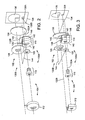
- FIG. 2 shows a perspective view of simplified optical systems (shown as 130A and 130B) for magnifying sight 104 and non-magnifying sight 102, respectively, as positioned within combination optical aiming device 100.
- FIG. 2 shows a single common viewing plane 134, though it will be understood that a plurality of common viewing planes 134 may intersect eye box 124 ( FIG. 1 ).
- Optical axis 132A of eyepiece 110 and optical axis 132B of optic 126 extend rearwardly toward common viewing plane 134.
- optical axis 132A is aligned with optical axes of other optical elements within magnifying sight 104 (e.g., objective 112), and is parallel with optical axis 132B of optic 126, within an acceptable tolerance.
- one or more portions of the optical system for either or both sights forward of optic 126 or eyepiece 110 may be aligned in different directions from optical axes 132B and 132A, respectively.
- portions of non-magnifying sight 102 and/or magnifying sight 104 may include folded optical paths and/or optical paths skewed with one another forward of optic 126 and eyepiece 110, respectively.
- Objective 112 may act as the aperture stop, and only light passing through objective 112 exits optical system 130A via eyepiece 110.
- an internal aperture inside the zoom erector system may act as the aperture stop.
- an exit pupil of a telescopic system is an image of an aperture stop of that system as seen from the eye side of that system, the exit pupil governs a radial extent of allowable eye pupil placement from which object light is visible at the eyepoint.
- the exit pupil effectively defines a radial size and shape of the longitudinal center of eyebox 124 along the magnified sight axis.
- the exit pupil generally corresponds to an image of objective 112 as viewed from behind eyepiece 110, or of an image of an aperture within the erector at low power. While the exit pupil is shaped according to the shape of objective 112, or of the internal aperture of erector system 116, the exit pupil is sized according to the magnifying power of magnifying sight 104. In the embodiment shown in FIG. 2 , two alternative exit pupils (shown as larger exit pupil 138A and smaller exit pupil 138B) are depicted within common viewing plane 134. Generally, the diameter of the smaller exit pupil is given by dividing the diameter of the objective lens by the optical power of the optical system at high power. In the embodiment shown in FIG.
- exit pupil 138A corresponds to a lower optical power setting for magnifying sight 104 while smaller exit pupil 138B corresponds to a higher optical power setting.
- both exit pupils may remain spaced apart from viewing zone 136 for the non-magnified sight within common viewing plane 134.
- the image light delivered to viewing zone 136 remains segregated from the light delivered to the exit pupil, providing discrete and distinct images from each sight.
- Viewing zone 136 corresponds to the area within common viewing plane 134 from which a viewer is able to observe the image of the aiming point using non-magnifying sight 102.
- an image of aiming light source 128 would be expected to be viewable from within viewing zone 136.
- viewing zone 136 represents the "effective" exit pupil of non-magnifying sight 104, so that viewing zone 136 has the same geometrical shape as a projection of optic 126 on common viewing plane 134, minus a thin shadow created by the support structure of aiming light source 128.
- one or more of optic 126 and one or more eye lenses included in eyepiece 110 may be shaped so that optical axes 132A and 132B may be positioned closer to one another than in a conventional sight. As shown in FIG. 2 , this proximity may be achieved in some embodiments by selectively removing portions (one of which is shown in phantom as a circular segment 140) of circular lenses to form a plurality of eye lenses 142.
- the shape of eye lenses 142 is constructed using a horizontal reference plane 144 that is parallel with the optical axis of the objective and a reference circle 148 centered about the optical axis of eyepiece 110.
- Horizontal reference plane 144 is tangent to a base 146 of optic 126, where base 146 refers to a bottom edge of optic 126 that positions horizontal reference plane 144 nearest to the optical axis of the objective and/or the eyepiece. Stated differently, an edge of optic 126 nearest the optical axis of the objective and/or the eyepiece is positioned tangent to horizontal reference plane 144. In turn, horizontal reference plane 144 intersects a reference circle 148 centered about the optical axis of the objective. In the embodiment shown in FIG. 2 , horizontal reference plane 144 is shown parallel with optical axis 132A, which is coaxial with the optical axis of objective 112.
- a reference circle 148 centered on the optical axis of that eye lens 142 surrounds that eye lens 142 and touches at least one edge of that eye lens 142. That is, a reference circle 148 for a particular eye lens 142 is coterminous with at least a portion of that particular eye lens 142.
- reference circle 148 surrounds eye lens 142, is centered about the optical axis of eye lens 142, and touches at least one edge of eye lens 142, so that reference circle 148 is coterminous with at least a portion of eye lens 142.
- reference circle 148 defines a circular segment of circle 148.
- the circular segment when overlaid on a circular lens, the circular segment may define dimensions for circular segment 140 so that, when circular segment 140 is removed, a truncated circular eye lens remains. For example, approximately an upper one-fourth of one or more eye lenses 142 having diameters in a range of 25 to 40 mm in eyepiece 110 may be removed in some embodiments.
- the remaining portion of reference circle 148 (that is, circle 148 less the circular segment) defines a shape that may be used to mold, cast, grind, or cut a truncated circular eye lens.
- Each eye lens 142 included in eyepiece 110 of the embodiment shown in FIG. 2 is shaped accordingly, though it will be appreciated that circular segments of different sizes may be removed from one or more eye lenses 142 in some embodiments.
- optical axis 132A is angled toward optical axis 132B (e.g., at an upward angle)
- an eye lens located closer to optical axis 132B may be truncated to a greater extent than another eye lens positioned farther from optical axis 132B.
- optic 126 is predominately or primarily positioned outside of a projection of a perimeter of a particular eye lens 142 along an axis parallel to the optical axis of objective lens 112.
- light transmitted by optic 126 is not obstructed or altered by light transmitted by magnifying sight 104.
- light from aiming light source 128 is not visible from eyepoint 108.
- Truncating eyepiece 110 has no effect on the size or shape of the exit pupil of magnifying sight 104. However, truncating one or more eye lenses in eyepiece 110 may alter the field of view (e.g., by removal thereof) as seen through magnifying sight 104. Accordingly, in some embodiments, a portion of optic 126 may be removed during fabrication as an alternative to truncation of one or more eye lenses to avoid altering the eyepiece field of view.
- approximately one-eighth or more of a circularly shaped partially reflective mirror (for a reflex sight) having a diameter in a range of 30 to 60 mm, or circularly shaped flat glass (for a holographic sight) having a diameter in a range of 30 to 60 mm, may be truncated to form a flat-based optic like that shown in FIG. 2 .
- a circularly shaped partially reflective mirror for a reflex sight
- circularly shaped flat glass for a holographic sight
- one or more lenses or optical elements included in objective 112 may be truncated. Truncating optical elements within objective 112 may allow magnifying sight 304 and non-magnifying sight 102 to be spaced closer together relative to the embodiment shown in FIG. 2 , though truncation of the objective may alter the shape of the exit pupil, particularly at the higher power settings. Because the exit pupil 338 is a conjugate image of the entrance pupil, exit pupil 338 exhibits a truncated shape if the truncation zone impinges on the entrance pupil diameter at a particular magnification.
- FIG. 3 shows a perspective view of simplified optical systems for a combination optical aiming device 100 including a magnifying sight 104 and a non-magnifying sight 102.
- magnifying sight 104 includes a truncated objective 312 including one or more truncated objective lenses.
- eyepiece 110 and optic 126 may have complementary shapes so that projections of eyepiece 110 and optic 126 in a plane normal to either one or both of optical axes 132A and 132B do not overlap one another.
- a circularly shaped region may be removed from a portion of an optic to permit placement of a circularly shaped eye lens therein.
- more than one circular segment may be removed from a circular lens to form an eye lens that is truncated on more than one edge.
- non-circular regions may be removed from respective starting pieces for the eye lens and optic so that the finished optical elements have complementary shapes.
- combination optical aiming device 100 includes a housing 106 having a mounting surface 150 that facilitates mounting the scope to a projectile weapon, to a tripod, or to any other suitable support surface (not shown).
- mounting surface 150 may be mounted to a projectile weapon so that magnifying sight 104 and/or non-magnifying sight 102 are aligned with a line of initial trajectory of the projectile weapon.
- Housing 106 also includes an internal adjustment mechanism 105 used to adjust non-magnifying sight 102 and/or magnifying sight 104 relative to one another.
- internal adjustment mechanism 105 may be configured to adjust a vertical and/or a horizontal alignment of non-magnifying sight 102 relative to an alignment of magnifying sight 104 before or after combination optical aiming device 100 is mounted to a projectile weapon.
- Housing 106 supports and encloses optical systems 130A and 130B.
- gaskets 152 included in housing 106 provide a weathertight environment 154 (which may also be water-free) within combination optical aiming device 100, so that optical elements, optical drives, and various support surfaces included within housing 106 may be protected from ambient conditions and/or condensation.
- sealing window 156 may include a flat, optically transmissive surface 158 through which optical axes 132A and 132B pass, respectively, en route to common viewing plane 134.
- sealing window 156 forms a unified viewing interface for both sights, presenting the user with a viewing window that may be easier to clean and maintain and potentially more engaging than some conventionally separated scopes.
- optically transmissive surface 158 may have a plano-convex lens positioned on either side thereof, effectively integrating a final eye lens of eyepiece 110 with sealing window 156. Integrating the final eye lens with sealing window 156 may contribute to a sealed environment formed within housing 106 while eliminating an additional optical element in the optical path of magnifying sight 104.
- FIG. 4 schematically shows a side cross-section view of an embodiment of an integrated eye lens 400 in simplified form. As shown in FIG.
- a flat surface 402A of one piano-convex lens 404A is optically bonded (e.g., using an index-matching adhesive) on a first, ambient, exterior side 406A of optically transmissive surface 158, and a flat surface 402B of another plano-convex lens 404B is optically bonded to a second, interior side 406B opposite plano-convex lens 404A.
- eye lens 400 is formed using a pair of planoconvex lenses 404A, 404B that sandwich an eye lens region of sealing window 156.
- an optical axis of each plano-convex lens is positioned in optical alignment with an incoming optical path of magnifying sight 104.
- plano-convex lenses 404A and 404B share a common optical axis 408 that is aligned with optical axis 132A of magnifying sight 104.
- Embodiments of combination optical aiming device 100 are suitable for use with projectile weapons (e.g., a bow, a rifle, a sidearm, etc.), and as a standalone scope (e.g., for use as a spotting scope).
- projectile weapons e.g., a bow, a rifle, a sidearm, etc.
- a standalone scope e.g., for use as a spotting scope.
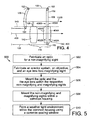
- FIG. 5 is a flowchart illustrating an embodiment of a method 500 for manufacturing or fabricating a combination optical aiming device, such as embodiments of combination optical aiming device 100 described herein. It will be appreciated that the embodiment of method 500 shown in FIG.
- method 500 may be supplemented with a process not shown in FIG. 5 , and/or one or more of the processes shown in FIG. 5 may be rearranged or omitted without departing from the scope of the present disclosure.
- method 500 includes fabricating an optic for a non-magnifying sight, and, at 504, fabricating an erector system, an objective, and an eye lens for a magnifying sight.
- fabricating the optic at 502 and/or fabricating the eye lens at 504 may include reshaping an optical structure into the optic and/or the eye lens, respectively.
- either one or both of the optic and the eye lens may be reshaped, so that, when mounted in the combination optical aiming device, the optic has a base that is both tangent to a base of the optic and parallel to an optical axis of the objective intersects a circle that surrounds the eye lens, touches at least one edge of the eye lens, and is centered about an optical axis of the eye lens, and the optic is positioned predominately outside of a projection of a perimeter of the eye lens parallel to the optical axis of the objective lens.
- reshaping an optical structure may include reshaping the optical structure so that either one or both of the optic and the eye lens has a shape that complements the other.
- a circular section may be removed from a circular lens, forming a truncated circular eye lens, a flat surface of which complements a flat base of the optic.
- a circular piece of flat glass used in a holographic sight or a circularly shaped partially reflective mirror used in a reflex sight may be trimmed to have a shape complementary to the eye lens (e.g., by removing a circularly shaped portion of the glass or mirror that complements a circular eye lens, or by removing a circular section of the glass or mirror to form a truncated circular optic that complements a truncated circular eye lens).
- fabricating the eye lens at 504 may include optically bonding a first plano-convex lens (e.g., using an index-matching adhesive) on a first, ambient, exterior side of an optically transmissive surface of a sealing window and optically bonding a flat surface of a second plano-convex lens to a second, interior side of the optically transmissive surface of the sealing window opposite the first plano-convex lens so that an optical axis of each plano-convex lens is positioned in optical alignment with an incoming optical path of the magnifying sight.
- a first plano-convex lens e.g., using an index-matching adhesive
- method 500 includes mounting the optic and the eye lens within the respective non-magnifying and magnifying sights so that a horizontal plane that is both tangent to a base of the optic and parallel to an optical axis of the eye lens intersects a circle that surrounds the eye lens, touches at least one edge of the eye lens, and is centered about the optical axis.
- method 500 includes mounting the non-magnifying and magnifying sights within a common housing. Finally, method 500 concludes at 510, forming a weathertight environment within the housing using a common sealing window through which optical axes of both the non-magnifying and magnifying sights pass en route to the common viewing plane.
- an embodiment of combination optical aiming device 100 includes a non-magnifying reflex sight having an optical center line positioned about 25 mm above an optical axis of a 2.5-8 x 32 mm telescopic sight.
- the reflex sight is formed starting with a 40 mm diameter glass partially reflective mirror that is trimmed to form an optic having approximately 20 mm of glass above its optical axis and approximately 15 mm of glass below its optical axis. That is, a 5 mm high circular segment of glass is removed from the bottom of the optic during shaping.
- the bottom of the optic is positioned approximately 10 mm above the optical axis of the eye lens.
- the bottom of the viewing zone of the optic is also about 15 mm below the optical axis of the optic and about 10 mm above the optical axis of the telescopic sight.
- the telescopic sight in this example includes an eye lens that is formed starting with a circularly shaped glass lens having a diameter of approximately 30 mm that is trimmed to have approximately 10 mm of glass above its optical axis and approximately 15 of glass below its optical axis, so that a 5 mm high circular segment of glass is removed from the top of the circular lens during shaping. Because the optical axis of the eye lens is positioned about 25 mm below the optical axis of the optic, the top of the eye lens is positioned approximately 15 mm below the optical axis of the optic. Moreover, if optical axes for the unshaped, or untrimmed, mirror and lens were positioned about 25 mm apart, diameters of those optical pieces would overlap one another by about 10 mm.
- the exit pupil of the telescopic sight has an exit pupil that is about 10.8 mm in diameter and centered on the optical axis of the telescopic sight. Accordingly, the top of the exit pupil is about 4.6 mm below the bottom of the viewing zone of the optic (i.e., (10 mm separation between the bottom of the viewing zone and the optical axis of the telescopic sight) - 0.5 x (10.8 mm telescopic sight exit pupil diameter at 2.5X magnification).
- the exit pupil of the telescopic sight has an exit pupil that is about 4 mm in diameter (i.e., 32 mm diameter objective lens divided by 8X magnification) and centered on the optical axis of the telescopic sight. Accordingly, the top of the exit pupil is about 8 mm below the bottom of the viewing zone of the optic (i.e., (10 mm separation between the bottom of the viewing zone and the optical axis of the telescopic sight) - 0.5 x (4 mm telescopic sight exit pupil diameter at 8X magnification).
- the exit pupil and the viewing zone are spaced apart from one another within a common viewing plane at the eyepoint, but are separated by a smaller dead zone than conventionally mounted reflex-on-telescopic sights, so that a user would be expected to use less vertical head movement when shifting between sights.
Landscapes
- Physics & Mathematics (AREA)
- Optics & Photonics (AREA)
- Astronomy & Astrophysics (AREA)
- General Physics & Mathematics (AREA)
- Engineering & Computer Science (AREA)
- General Engineering & Computer Science (AREA)
- Telescopes (AREA)
- Lenses (AREA)
Description
- Telescopic sights, such as rifle scopes, optically magnify distant objects but only provide a narrow field of view. While a distant object may be easier to resolve with a telescopic sight, the narrow field of view may make it difficult to track movement of the object. At close ranges, it is sometimes preferable to provide an alternative aiming point to one eye using a sight having no additional magnification in order to match a view seen by the other, naked eye. In an effort to provide an enlarged view and a view with a wider field of view without swapping scopes, a reflex sight is often mounted to a telescopic sight, so that a user may choose which sight to use when viewing an object according to the circumstances. While such approaches may avoid removing and replacing one scope with another, the inventor has recognized that the head and/or weapon movement required for a user to switch from one sight to another may lead to loss of aim and delay in targeting. Publication
CA 670 887 A discloses an optical aiming-device of particular interest. -
-
FIG. 1 schematically shows a side cross-section view of an embodiment of a combination optical aiming device including examples of a magnifying sight and a non-magnifying optical sight according to the present disclosure. -
FIG. 2 shows a perspective view of example simplified optical systems included in an embodiment of a combination optical aiming device according to the present disclosure. -
FIG. 3 shows a perspective view of example simplified optical systems included in another embodiment of a combination optical aiming device according to the present disclosure. -
FIG. 4 schematically shows a side cross-section view of an example eye lens integrated with a sealing window according to an embodiment of the present disclosure. -
FIG. 5 is a flowchart for an embodiment of a method of manufacturing a combination optical aiming device according to the present disclosure. -
FIG. 1 schematically shows a side cross-section of a combination optical aiming device 100 (depicted as a riflescope inFIG. 1 , though in some embodiments combinationoptical aiming device 100 may be included in a spotting scope or an archery scope) according to an embodiment of the present disclosure. Combinationoptical aiming device 100 includes a non-magnifyingsight 102 and amagnifying sight 104 for viewing differently magnified images of a distant object from a common viewing plane or position. In the embodiment shown inFIG. 1 , non-magnifyingsight 102 andmagnifying sight 104 are shown mounted within acommon housing 106. - Magnifying sight 104 is a telescope that allows a user to view a magnified, or enlarged, image of a distant object at an
eyepoint 108. The image is viewable via an exit pupil at a location behind the sight, preferably ateyepoint 108. Magnifying sight 104 includes aneyepiece 110 that may include one or more eye lenses. Magnifying sight 104 also includes an objective 112 that may include one or more objective lenses and/or reflectors.Eyepiece 110 and objective 112 are positioned at opposite ends of the sight in the example shown inFIG. 1 . Typically, objective 112 gathers light from the distant object and produces an inverted image of the object at frontfocal plane 114, positioned behindobjective 112. Anerector system 116 rectifies the inverted image, producing an erect image of the object at a rear focal plane 118 positioned behind frontfocal plane 114 anderector system 116.Erector system 116 may include one or more lenses or other optical elements (e.g., reflectors and/or prisms) used to produce the erect image. Areticle 120 is shown inFIG. 1 at rear focal plane 118, though in someembodiments reticle 120 may be positioned or located at frontfocal plane 114. - In the embodiment shown in
FIG. 1 ,moveable lens elements 122 oferector system 116 adjust the optical power ofmagnifying sight 104. In some embodiments, optical power may be adjusted by rotating a power selector ring (not shown) or other drive mechanism to drivemoveable lens elements 122 along an optical axis, or optical centerline, to adjust image magnification ofmagnifying sight 104 as perceived by a user viewing the erect image througheyepiece 110. - In use, the distant object is visible via
magnifying sight 104 within aneyebox 124. That is,eyebox 124 defines a region behindmagnifying sight 104 in which the distant object is viewable with the sight. The radial size and shape ofeyebox 124, extending from an optical axis ofeyepiece 110, and the depth of the eyebox 124 (a front-to-back depth shown in brackets inFIG. 1 ) are governed by a combination of the size and shape of the bundle of off-axis rays forming the exit pupil and the eye relief ofmagnifying sight 104. Accordingly, the distant object will be viewable viamagnifying sight 104 if a viewing plane intersectseye box 124. Aligning the pupil of the viewer's eye witheye box 124 would be expected to prevent vignetting when viewing the distant object. - While a magnified view of the distant object may ease aiming in some settings (e.g., where the object is too far away to be easily resolved without magnification), the viewer's depth perception may be altered by the telescopic view, or the sharpness of close targets may be degraded. This may make it difficult to maintain proper eye relief or target aim point when sighting on a moving target. In contrast, non-magnifying
sight 102 may be used at almost any distance from the eye without interfering with the viewer's depth perception or perceived sharpness of the target. - Non-magnifying
sight 102 is an optical device that allows a user to view an image of an aiming point superimposed on a field of view of non-magnifyingsight 102 in the far field via an optic 126. For ease of illustration, the examples of non-magnifyingsight 102 described herein generally relate to reflex sights. Nevertheless, it will be appreciated that some embodiments of combinationoptical aiming device 100 may include a holographic sight that allows a user to look through optic 126 and view an aiming point (e.g., a holographic reticle image) illuminated by an aiming light source (e.g., a laser) and superimposed on a distant object in the far field. In contrast, reflex sights often position a source for the aiming point, such as an illuminated "dot" or reticle, at or near a focal point of a partially reflective optic that transmits some light received from the distant object and reflects some light received from the source. In the embodiment shown inFIG. 1 , optic 126 is illustrated as a curved mirror, though in some other embodiments, optic 126 may include a flat reflector used with a collimated light source. The embodiment shown inFIG. 1 also shows aiminglight source 128 mounted on a support structure. In some embodiments, the support structure may be shaped as a thin post or blade-like structure. Non-limiting examples of such support structures may have cross-sectional profiles having a thickness of about 1 mm and a width of about 5mm. Of course, it will be appreciated that the height of such support structures may vary in order to position aiminglight source 128 primarily at an optical axis of optic 126. - The example non-magnifying
sight 102 shown inFIG. 1 illustrates a reflex sight in which optic 126 collimates light received from aiminglight source 128.Aiming light source 128 may include a light-emitting diode (LED) (e.g., a chip-mounted LED in some embodiments) or any other suitable light source. Because aiminglight source 128 is positioned at, or slightly closer than the focal point of optic 126, a virtual image of aiminglight source 128 will appear, to the viewer, as if positioned at a desired range in the far field. - While some previous scopes have attempted to mount a non-magnifying sight to a telescopic sight, the physical size of many conventional telescopic sights and non-magnifying sights often requires the user to make undesirably large head movements (e.g., 25 mm or more) when switching between them. If mounted to a projectile weapon, such as a rifle, the movement may cause the user to lose contact, sometimes referred to as "cheek weld," between the user's cheek and the stock of the weapon. Loss of cheek weld may lead to loss of aim and delay in targeting when firing a weapon with substantial recoil.
- Accordingly, the embodiments disclosed herein include combination optical aiming devices for viewing differently magnified images of a distant object and methods for manufacturing the same. As explained in more detail below, one or more of optic 126 and one or more eye lens elements included in
eyepiece 110 may be shaped so that non-magnifyingsight 102 andmagnifying sight 104 may be positioned closer to one another than the conventionally mounted sights described above. Put another way, optic 126 andeyepiece 110 are selectively positioned within combinationoptical aiming device 100 to reduce the spacing between those sights (that is, to reduce a "dead zone" separating the sights from one another, which may be occupied by housing and hardware elements) while generally maintaining segregation between light transmitted by each sight. This potentially may reduce user head movement when switching betweennon-magnifying sight 102 and magnifyingsight 104. -
FIG. 2 shows a perspective view of simplified optical systems (shown as 130A and 130B) formagnifying sight 104 and non-magnifyingsight 102, respectively, as positioned within combinationoptical aiming device 100. For ease of illustration,FIG. 2 shows a singlecommon viewing plane 134, though it will be understood that a plurality ofcommon viewing planes 134 may intersect eye box 124 (FIG. 1 ). -
Optical axis 132A ofeyepiece 110 andoptical axis 132B of optic 126 extend rearwardly towardcommon viewing plane 134. In the embodiment shown inFIG. 2 ,optical axis 132A is aligned with optical axes of other optical elements within magnifying sight 104 (e.g., objective 112), and is parallel withoptical axis 132B of optic 126, within an acceptable tolerance. Alternatively, in some embodiments, one or more portions of the optical system for either or both sights forward of optic 126 oreyepiece 110 may be aligned in different directions fromoptical axes sight 102 and/ormagnifying sight 104 may include folded optical paths and/or optical paths skewed with one another forward of optic 126 andeyepiece 110, respectively. -
Objective 112 may act as the aperture stop, and only light passing through objective 112 exitsoptical system 130A viaeyepiece 110. Alternatively, usually at low magnification settings of a zoom erector system, an internal aperture inside the zoom erector system may act as the aperture stop. Because an exit pupil of a telescopic system is an image of an aperture stop of that system as seen from the eye side of that system, the exit pupil governs a radial extent of allowable eye pupil placement from which object light is visible at the eyepoint. As introduced above, the exit pupil effectively defines a radial size and shape of the longitudinal center ofeyebox 124 along the magnified sight axis. In the context of magnifyingsight 104, the exit pupil generally corresponds to an image of objective 112 as viewed from behindeyepiece 110, or of an image of an aperture within the erector at low power. While the exit pupil is shaped according to the shape of objective 112, or of the internal aperture oferector system 116, the exit pupil is sized according to the magnifying power of magnifyingsight 104. In the embodiment shown inFIG. 2 , two alternative exit pupils (shown aslarger exit pupil 138A andsmaller exit pupil 138B) are depicted withincommon viewing plane 134. Generally, the diameter of the smaller exit pupil is given by dividing the diameter of the objective lens by the optical power of the optical system at high power. In the embodiment shown inFIG. 2 ,larger exit pupil 138A corresponds to a lower optical power setting for magnifyingsight 104 whilesmaller exit pupil 138B corresponds to a higher optical power setting. Regardless of the power setting, in some embodiments, both exit pupils may remain spaced apart fromviewing zone 136 for the non-magnified sight withincommon viewing plane 134. In such embodiments, the image light delivered toviewing zone 136 remains segregated from the light delivered to the exit pupil, providing discrete and distinct images from each sight. -
Viewing zone 136 corresponds to the area withincommon viewing plane 134 from which a viewer is able to observe the image of the aiming point usingnon-magnifying sight 102. In the example shown inFIG. 2 , an image of aiminglight source 128 would be expected to be viewable from withinviewing zone 136. Conceptually,viewing zone 136 represents the "effective" exit pupil ofnon-magnifying sight 104, so thatviewing zone 136 has the same geometrical shape as a projection ofoptic 126 oncommon viewing plane 134, minus a thin shadow created by the support structure of aiminglight source 128. - As introduced above, one or more of
optic 126 and one or more eye lenses included ineyepiece 110 may be shaped so thatoptical axes FIG. 2 , this proximity may be achieved in some embodiments by selectively removing portions (one of which is shown in phantom as a circular segment 140) of circular lenses to form a plurality ofeye lenses 142. The shape ofeye lenses 142 is constructed using ahorizontal reference plane 144 that is parallel with the optical axis of the objective and areference circle 148 centered about the optical axis ofeyepiece 110. -
Horizontal reference plane 144 is tangent to a base 146 ofoptic 126, where base 146 refers to a bottom edge ofoptic 126 that positionshorizontal reference plane 144 nearest to the optical axis of the objective and/or the eyepiece. Stated differently, an edge ofoptic 126 nearest the optical axis of the objective and/or the eyepiece is positioned tangent tohorizontal reference plane 144. In turn,horizontal reference plane 144 intersects areference circle 148 centered about the optical axis of the objective. In the embodiment shown inFIG. 2 ,horizontal reference plane 144 is shown parallel withoptical axis 132A, which is coaxial with the optical axis of objective 112. - For a
particular eye lens 142, areference circle 148 centered on the optical axis of thateye lens 142 surrounds thateye lens 142 and touches at least one edge of thateye lens 142. That is, areference circle 148 for aparticular eye lens 142 is coterminous with at least a portion of thatparticular eye lens 142. For eachshaped eye lens 142,reference circle 148 surroundseye lens 142, is centered about the optical axis ofeye lens 142, and touches at least one edge ofeye lens 142, so thatreference circle 148 is coterminous with at least a portion ofeye lens 142. - The intersection of
reference circle 148 andhorizontal reference plane 144 defines a circular segment ofcircle 148. In some embodiments, when overlaid on a circular lens, the circular segment may define dimensions forcircular segment 140 so that, whencircular segment 140 is removed, a truncated circular eye lens remains. For example, approximately an upper one-fourth of one ormore eye lenses 142 having diameters in a range of 25 to 40 mm ineyepiece 110 may be removed in some embodiments. In some other embodiments, the remaining portion of reference circle 148 (that is,circle 148 less the circular segment) defines a shape that may be used to mold, cast, grind, or cut a truncated circular eye lens. - Each
eye lens 142 included ineyepiece 110 of the embodiment shown inFIG. 2 is shaped accordingly, though it will be appreciated that circular segments of different sizes may be removed from one ormore eye lenses 142 in some embodiments. For example, in an embodiment whereoptical axis 132A is angled towardoptical axis 132B (e.g., at an upward angle), an eye lens located closer tooptical axis 132B may be truncated to a greater extent than another eye lens positioned farther fromoptical axis 132B. - One consequence of the shaping of one or more eye lenses 142 (or in addition or in the alternative, in some embodiments, the shaping of optic 126) is that
optic 126 is predominately or primarily positioned outside of a projection of a perimeter of aparticular eye lens 142 along an axis parallel to the optical axis ofobjective lens 112. In turn, light transmitted byoptic 126 is not obstructed or altered by light transmitted by magnifyingsight 104. Put another way, light from aiminglight source 128 is not visible fromeyepoint 108. - Truncating
eyepiece 110 has no effect on the size or shape of the exit pupil of magnifyingsight 104. However, truncating one or more eye lenses ineyepiece 110 may alter the field of view (e.g., by removal thereof) as seen through magnifyingsight 104. Accordingly, in some embodiments, a portion ofoptic 126 may be removed during fabrication as an alternative to truncation of one or more eye lenses to avoid altering the eyepiece field of view. For example, approximately one-eighth or more of a circularly shaped partially reflective mirror (for a reflex sight) having a diameter in a range of 30 to 60 mm, or circularly shaped flat glass (for a holographic sight) having a diameter in a range of 30 to 60 mm, may be truncated to form a flat-based optic like that shown inFIG. 2 . In addition, if truncation of the optic is combined with truncation ofeyepiece 110, even closer spacing ofnon-magnifying sight 102 andmagnifying sight 104 may be realized in some embodiments. - Additionally or alternatively, in some embodiments, one or more lenses or optical elements included in objective 112 may be truncated. Truncating optical elements within objective 112 may allow magnifying
sight 304 andnon-magnifying sight 102 to be spaced closer together relative to the embodiment shown inFIG. 2 , though truncation of the objective may alter the shape of the exit pupil, particularly at the higher power settings. Because theexit pupil 338 is a conjugate image of the entrance pupil,exit pupil 338 exhibits a truncated shape if the truncation zone impinges on the entrance pupil diameter at a particular magnification. In some embodiments, up to about one-fourth of one or more circularly shaped objective lenses having diameters in a range of 20 to 60 mm may be removed to formtruncated objective 312. For example,FIG. 3 shows a perspective view of simplified optical systems for a combination optical aimingdevice 100 including amagnifying sight 104 and anon-magnifying sight 102. In the example shown inFIG. 3 , magnifyingsight 104 includes atruncated objective 312 including one or more truncated objective lenses. - Combination optical aiming devices according to the present disclosure are not limited to those having truncated circular optical elements, nor is the fabrication thereof limited to the removal of circular segments from circular lenses. In some embodiments,
eyepiece 110 and optic 126 may have complementary shapes so that projections ofeyepiece 110 and optic 126 in a plane normal to either one or both ofoptical axes - Turning back to
FIG. 1 , combination optical aimingdevice 100 includes ahousing 106 having a mountingsurface 150 that facilitates mounting the scope to a projectile weapon, to a tripod, or to any other suitable support surface (not shown). For example, mountingsurface 150 may be mounted to a projectile weapon so that magnifyingsight 104 and/ornon-magnifying sight 102 are aligned with a line of initial trajectory of the projectile weapon.Housing 106 also includes aninternal adjustment mechanism 105 used to adjustnon-magnifying sight 102 and/or magnifyingsight 104 relative to one another. For example,internal adjustment mechanism 105 may be configured to adjust a vertical and/or a horizontal alignment ofnon-magnifying sight 102 relative to an alignment of magnifyingsight 104 before or after combination optical aimingdevice 100 is mounted to a projectile weapon. -
Housing 106 supports and enclosesoptical systems FIG. 1 ,gaskets 152 included inhousing 106 provide a weathertight environment 154 (which may also be water-free) within combination optical aimingdevice 100, so that optical elements, optical drives, and various support surfaces included withinhousing 106 may be protected from ambient conditions and/or condensation. - In some embodiments, sealing
window 156 may include a flat, opticallytransmissive surface 158 through whichoptical axes common viewing plane 134. In such embodiments, sealingwindow 156 forms a unified viewing interface for both sights, presenting the user with a viewing window that may be easier to clean and maintain and potentially more engaging than some conventionally separated scopes. - In some embodiments, optically
transmissive surface 158 may have a plano-convex lens positioned on either side thereof, effectively integrating a final eye lens ofeyepiece 110 with sealingwindow 156. Integrating the final eye lens with sealingwindow 156 may contribute to a sealed environment formed withinhousing 106 while eliminating an additional optical element in the optical path of magnifyingsight 104. For example,FIG. 4 schematically shows a side cross-section view of an embodiment of an integrated eye lens 400 in simplified form. As shown inFIG. 4 , a flat surface 402A of one piano-convex lens 404A is optically bonded (e.g., using an index-matching adhesive) on a first, ambient,exterior side 406A of opticallytransmissive surface 158, and aflat surface 402B of another plano-convex lens 404B is optically bonded to a second,interior side 406B opposite plano-convex lens 404A. Thus, eye lens 400 is formed using a pair ofplanoconvex lenses window 156. In such an embodiment, an optical axis of each plano-convex lens is positioned in optical alignment with an incoming optical path of magnifyingsight 104. In the example shown inFIG. 4 , plano-convex lenses optical axis 408 that is aligned withoptical axis 132A of magnifyingsight 104. - Embodiments of combination optical aiming
device 100, such as those shown inFIGS. 1-4 , are suitable for use with projectile weapons (e.g., a bow, a rifle, a sidearm, etc.), and as a standalone scope (e.g., for use as a spotting scope). Naturally, application-based variation may lead to some variation in form factor and/or manufacture, but it will be appreciated that embodiments of combination optical aimingdevice 100 may be manufactured in any suitable fashion. For example,FIG. 5 is a flowchart illustrating an embodiment of amethod 500 for manufacturing or fabricating a combination optical aiming device, such as embodiments of combination optical aimingdevice 100 described herein. It will be appreciated that the embodiment ofmethod 500 shown inFIG. 5 is provided for illustrative purposes only. In some embodiments,method 500 may be supplemented with a process not shown inFIG. 5 , and/or one or more of the processes shown inFIG. 5 may be rearranged or omitted without departing from the scope of the present disclosure. - At 502,
method 500 includes fabricating an optic for a non-magnifying sight, and, at 504, fabricating an erector system, an objective, and an eye lens for a magnifying sight. In some embodiments, fabricating the optic at 502 and/or fabricating the eye lens at 504 may include reshaping an optical structure into the optic and/or the eye lens, respectively. In such embodiments, either one or both of the optic and the eye lens may be reshaped, so that, when mounted in the combination optical aiming device, the optic has a base that is both tangent to a base of the optic and parallel to an optical axis of the objective intersects a circle that surrounds the eye lens, touches at least one edge of the eye lens, and is centered about an optical axis of the eye lens, and the optic is positioned predominately outside of a projection of a perimeter of the eye lens parallel to the optical axis of the objective lens. - In some embodiments, reshaping an optical structure may include reshaping the optical structure so that either one or both of the optic and the eye lens has a shape that complements the other. For example, a circular section may be removed from a circular lens, forming a truncated circular eye lens, a flat surface of which complements a flat base of the optic. In another example, a circular piece of flat glass used in a holographic sight or a circularly shaped partially reflective mirror used in a reflex sight may be trimmed to have a shape complementary to the eye lens (e.g., by removing a circularly shaped portion of the glass or mirror that complements a circular eye lens, or by removing a circular section of the glass or mirror to form a truncated circular optic that complements a truncated circular eye lens).
- In some embodiments, fabricating the eye lens at 504 may include optically bonding a first plano-convex lens (e.g., using an index-matching adhesive) on a first, ambient, exterior side of an optically transmissive surface of a sealing window and optically bonding a flat surface of a second plano-convex lens to a second, interior side of the optically transmissive surface of the sealing window opposite the first plano-convex lens so that an optical axis of each plano-convex lens is positioned in optical alignment with an incoming optical path of the magnifying sight.
- At 506,
method 500 includes mounting the optic and the eye lens within the respective non-magnifying and magnifying sights so that a horizontal plane that is both tangent to a base of the optic and parallel to an optical axis of the eye lens intersects a circle that surrounds the eye lens, touches at least one edge of the eye lens, and is centered about the optical axis. - At 508,
method 500 includes mounting the non-magnifying and magnifying sights within a common housing. Finally,method 500 concludes at 510, forming a weathertight environment within the housing using a common sealing window through which optical axes of both the non-magnifying and magnifying sights pass en route to the common viewing plane. - In one non-limiting prophetic example, an embodiment of combination optical aiming
device 100 includes a non-magnifying reflex sight having an optical center line positioned about 25 mm above an optical axis of a 2.5-8 x 32 mm telescopic sight. In this example, the reflex sight is formed starting with a 40 mm diameter glass partially reflective mirror that is trimmed to form an optic having approximately 20 mm of glass above its optical axis and approximately 15 mm of glass below its optical axis. That is, a 5 mm high circular segment of glass is removed from the bottom of the optic during shaping. Because the optical axis of the optic is positioned about 25 mm above from the optical axis of the eye piece, the bottom of the optic is positioned approximately 10 mm above the optical axis of the eye lens. In turn, the bottom of the viewing zone of the optic is also about 15 mm below the optical axis of the optic and about 10 mm above the optical axis of the telescopic sight. - The telescopic sight in this example includes an eye lens that is formed starting with a circularly shaped glass lens having a diameter of approximately 30 mm that is trimmed to have approximately 10 mm of glass above its optical axis and approximately 15 of glass below its optical axis, so that a 5 mm high circular segment of glass is removed from the top of the circular lens during shaping. Because the optical axis of the eye lens is positioned about 25 mm below the optical axis of the optic, the top of the eye lens is positioned approximately 15 mm below the optical axis of the optic. Moreover, if optical axes for the unshaped, or untrimmed, mirror and lens were positioned about 25 mm apart, diameters of those optical pieces would overlap one another by about 10 mm.
- At low power (2.5X magnification), the exit pupil of the telescopic sight has an exit pupil that is about 10.8 mm in diameter and centered on the optical axis of the telescopic sight. Accordingly, the top of the exit pupil is about 4.6 mm below the bottom of the viewing zone of the optic (i.e., (10 mm separation between the bottom of the viewing zone and the optical axis of the telescopic sight) - 0.5 x (10.8 mm telescopic sight exit pupil diameter at 2.5X magnification). At high power (8X magnification), the exit pupil of the telescopic sight has an exit pupil that is about 4 mm in diameter (i.e., 32 mm diameter objective lens divided by 8X magnification) and centered on the optical axis of the telescopic sight. Accordingly, the top of the exit pupil is about 8 mm below the bottom of the viewing zone of the optic (i.e., (10 mm separation between the bottom of the viewing zone and the optical axis of the telescopic sight) - 0.5 x (4 mm telescopic sight exit pupil diameter at 8X magnification). Consequently, the exit pupil and the viewing zone are spaced apart from one another within a common viewing plane at the eyepoint, but are separated by a smaller dead zone than conventionally mounted reflex-on-telescopic sights, so that a user would be expected to use less vertical head movement when shifting between sights.
- The scope of the present invention should, therefore, be determined only by the flollowing claims.
Claims (15)
- A combination optical aiming device (100) for viewing differently magnified images of a distant object from a common viewing plane (134), the combination optical aiming device comprising:an erector system (116);a non-magnifying sight (102) having an optic (126) for viewing an image of an aiming point from a viewing zone located within a common viewing plane; anda magnifying sight (104) having an objective (112) for gathering light from the distant object and having a truncated eye lens (142) for viewing a magnified image of the distant object at an eyepoint (108) located in the common viewing plane, the optic and the truncated eye lens being positioned relative to one another so as to position the optic predominately outside of a projection of a perimeter of the truncated eye lens, the projection being parallel to an optical axis of the objective.
- The combination optical aiming device of claim 1, wherein the optic is truncated.
- The combination optical aiming device of claim 1 or 2, wherein the optic and the truncated eye lens are positioned so that a horizontal plane (144) that is both tangent to a base of the optic and parallel to an optical axis of the objective intersects a reference circle (148) that surrounds the truncated eye lens, touches at least one edge of the truncated eye lens, and is centered about an optical axis (132A) of the truncated eye lens.
- The combination optical aiming device of any preceding claim, wherein the eyepoint and the viewing zone are spaced apart from one another within the common viewing plane.
- The combination optical aiming device of any preceding claim, wherein the non-magnifying sight includes a reflex sight, and the aiming point is generated by an aiming light source (128) included in the combination optical aiming device.
- The combination optical aiming device of any preceding claim, wherein the magnifying and non-magnifying sights are positioned so that respective aiming lines-of-sight for the sights are substantially parallel with one another.
- The combination optical aiming device of any preceding claim, wherein the magnifying sight includes a truncated objective lens (312).
- The combination optical aiming device of any preceding claim, wherein the eye lens and the optic have complementary shapes.
- The combination optical aiming device of claim 3, wherein the eye lens has a truncated circular shape formed by removal of a circular segment from the reference circle, the circular segment having a shape defined by intersection of the horizontal plane with the reference circle.
- The combination optical aiming device of any preceding claim, further comprising:a common housing (106); anda sealing window (156) used to form a weathertight environment within the housing.
- The combination optical aiming device of claim 10, wherein light received from the distant object by both the non-magnifying sight and the magnifying sight passes through the sealing window en route to the common viewing plane; or
wherein the eye lens and the optic are positioned between the object and a flat, optically transmissive surface of the sealing window so that the sealing window forms a unified viewing interface for the non-magnifying and magnifying sights; or
wherein the eye lens is formed using a pair of planoconvex lenses (404A, 404B) that sandwich an eye lens region of the sealing window. - The combination optical aiming device of any of any preceding claim, wherein the optic is configured for viewing, from the common viewing plane, the image of the aiming point superimposed on a non-magnified image of a distant object; or
wherein the optic is configured for viewing the image of the aiming point. superimposed on a field of view of the non-magnifying sight from the viewing zone. - A method of manufacturing a combination optical aiming device (100) for viewing differently magnified images of a distant object from a common viewing plane (134), the method comprising:fabricating an optic (126) for a non-magnifying sight (102);fabricating an erector system (116), an objective (112), and an eye lens (142) for a magnifying sight (104); andmounting the optic, the objective and the eye lens so that a horizontal plane (144) that is both tangent to a base of the optic and parallel to an optical axis of the objective intersects a reference circle (148) that surrounds the eye lens, touches at least one edge of the eye lens, and is centered about an optical axis (132A) of the eye lens so as to position the optic predominately outside of a projection of a perimeter of the eye lens, the projection being parallel to the optical axis of the objective.
- The method of claim 13, further comprising:mounting the non-magnifying and magnifying sights within a common housing (106);forming a weathertight environment within the housing using a common sealing window (156) through which optical axes of both the non-magnifying and magnifying sights pass en route to the common viewing plane.
- The method of claim 13 or 14, wherein fabricating the eye lens includes optically bonding a pair of plano-convex lenses (404A, 404B) on either side of an eye lens region of the sealing window.
Applications Claiming Priority (1)
| Application Number | Priority Date | Filing Date | Title |
|---|---|---|---|
| US13/838,395 US9291808B2 (en) | 2013-03-15 | 2013-03-15 | Combination optical aiming device for projectile weapons |
Publications (2)
| Publication Number | Publication Date |
|---|---|
| EP2778738A1 EP2778738A1 (en) | 2014-09-17 |
| EP2778738B1 true EP2778738B1 (en) | 2015-10-14 |
Family
ID=50439134
Family Applications (1)
| Application Number | Title | Priority Date | Filing Date |
|---|---|---|---|
| EP14160129.4A Not-in-force EP2778738B1 (en) | 2013-03-15 | 2014-03-14 | Aiming optical sight using truncated lenses |
Country Status (4)
| Country | Link |
|---|---|
| US (1) | US9291808B2 (en) |
| EP (1) | EP2778738B1 (en) |
| AU (1) | AU2014201504B2 (en) |
| CA (1) | CA2846792C (en) |
Families Citing this family (11)
| Publication number | Priority date | Publication date | Assignee | Title |
|---|---|---|---|---|
| US10060702B2 (en) | 2013-03-15 | 2018-08-28 | Leupold & Stevens, Inc. | Dual field optical aiming system for projectile weapons |
| EP3019812B1 (en) | 2013-07-09 | 2018-09-05 | Zieger, Cory | Modular holographic sighting system |
| EP3022514B1 (en) | 2013-07-15 | 2021-09-08 | Optiflow, LLC | Compact weapon sight and method of stabilizing an output wavelength of a weapon sight |
| EP3314314A4 (en) | 2015-06-26 | 2018-06-20 | Ziel Optics, Inc. | Holographic weapon sight with optimized beam angles |
| US10254532B2 (en) | 2015-06-26 | 2019-04-09 | Ziel Optics, Inc. | Hybrid holographic sight |
| CN109029112B (en) * | 2018-08-24 | 2023-09-19 | 宁波德远精工科技有限公司 | Bulb laser module |
| USD961714S1 (en) | 2019-11-21 | 2022-08-23 | Eotech, Llc | Weapon sight |
| US11486675B2 (en) * | 2019-11-21 | 2022-11-01 | Eotech, Llc | Weapon sight with tapered housing |
| US11976901B2 (en) | 2021-06-07 | 2024-05-07 | Sturm, Ruger & Company, Inc. | Passively illuminated fiber optic reflex sights for firearms |
| US12571610B2 (en) | 2021-06-07 | 2026-03-10 | Sturm, Ruger & Company, Inc. | Optical sight for firearm with integral rear sight |
| US20250277967A1 (en) * | 2024-03-01 | 2025-09-04 | Robert L. Gilmer | Dual view far field magnifying bifocal |
Family Cites Families (13)
| Publication number | Priority date | Publication date | Assignee | Title |
|---|---|---|---|---|
| CA670887A (en) | 1963-09-24 | Hopp Gerhard | Observation and sighting telescope | |
| US2388673A (en) | 1944-06-09 | 1945-11-13 | Leo H Brown | Dual power optical system |
| US2512153A (en) | 1947-05-23 | 1950-06-20 | Us Sec War | Split-field dual-power telescope |
| US2527719A (en) | 1947-11-28 | 1950-10-31 | Jesse L Greenstein | Dual power split-field antitank telescope |
| GB9020902D0 (en) | 1990-09-26 | 1990-11-07 | Optics & Vision Ltd | Optical systems,telescopes and binoculars |
| US5161051A (en) | 1990-12-13 | 1992-11-03 | Hughes Aircraft Company | Simultaneous dual field of view sensor |
| US5349469A (en) | 1992-12-22 | 1994-09-20 | Hughes Aircraft Company | Optical mode switching system |
| GB9620001D0 (en) | 1996-09-25 | 1996-11-13 | Firearms Research Ltd | Optical sighting devices |
| US20040075894A1 (en) * | 2001-12-10 | 2004-04-22 | Shafer David R. | Catadioptric reduction objective |
| US6487809B1 (en) | 2001-12-19 | 2002-12-03 | American Technologies Network Corporation | Optical sight system with wide range of shooting distances |
| US7522356B1 (en) * | 2005-06-08 | 2009-04-21 | Raytheon Company | Sight having an asymmetric field of view and its manufacture |
| US7676137B2 (en) * | 2007-05-22 | 2010-03-09 | Trijicon, Inc. | Optical sight |
| US8599481B2 (en) | 2009-08-20 | 2013-12-03 | Kruger Optical, Inc. | Flat walled scope and method of manufacturing the same |
-
2013
- 2013-03-15 US US13/838,395 patent/US9291808B2/en not_active Expired - Fee Related
-
2014
- 2014-03-13 CA CA2846792A patent/CA2846792C/en not_active Expired - Fee Related
- 2014-03-13 AU AU2014201504A patent/AU2014201504B2/en not_active Ceased
- 2014-03-14 EP EP14160129.4A patent/EP2778738B1/en not_active Not-in-force
Also Published As
| Publication number | Publication date |
|---|---|
| AU2014201504A1 (en) | 2014-10-02 |
| AU2014201504B2 (en) | 2016-11-03 |
| US9291808B2 (en) | 2016-03-22 |
| US20140268323A1 (en) | 2014-09-18 |
| CA2846792C (en) | 2017-03-28 |
| CA2846792A1 (en) | 2014-09-15 |
| EP2778738A1 (en) | 2014-09-17 |
Similar Documents
| Publication | Publication Date | Title |
|---|---|---|
| CA2846792C (en) | Combination optical aiming device for projectile weapons | |
| US20240426574A1 (en) | Dual focal plane reticles for optical sighting devices | |
| US9568277B2 (en) | Dual field optical aiming system for projectile weapons | |
| EP2215513B1 (en) | Improvements in or relating to head mounted display systems | |
| US7762683B2 (en) | Optical device with tilt and power microlenses | |
| US10060702B2 (en) | Dual field optical aiming system for projectile weapons | |
| US9417037B2 (en) | Telescopic gun sight with offset eyepoint | |
| CN102692707A (en) | Head-mounted display device | |
| EP3311098B1 (en) | Dual focal plane reticles for optical sighting devices | |
| US9494787B1 (en) | Direct view zoom scope with single focal plane and adaptable reticle | |
| EP2695014B1 (en) | Enhanced periscope | |
| CN106461949A (en) | Head-up display device and lighting unit thereof | |
| JP2011128500A (en) | Lens optical system, image display device and head-up display | |
| EP2746832B1 (en) | Virtual image display device | |
| EP3303975B1 (en) | Telescopic gun sight with offset eyepoint | |
| US9891022B2 (en) | Optical sight | |
| JPWO2019030912A1 (en) | Dot site | |
| KR101440057B1 (en) | Separable dot sight for day and night sight system | |
| EP3303976A1 (en) | Combination gun sight with single eyepoint | |
| US7643210B2 (en) | Night vision binoculars | |
| US20160091721A1 (en) | Display device | |
| KR20170139576A (en) | Equipment for improving binocular vision | |
| HK1222457B (en) | Optical sight |
Legal Events
| Date | Code | Title | Description |
|---|---|---|---|
| 17P | Request for examination filed |
Effective date: 20140314 |
|
| AK | Designated contracting states |
Kind code of ref document: A1 Designated state(s): AL AT BE BG CH CY CZ DE DK EE ES FI FR GB GR HR HU IE IS IT LI LT LU LV MC MK MT NL NO PL PT RO RS SE SI SK SM TR |
|
| AX | Request for extension of the european patent |
Extension state: BA ME |
|
| PUAI | Public reference made under article 153(3) epc to a published international application that has entered the european phase |
Free format text: ORIGINAL CODE: 0009012 |
|
| GRAP | Despatch of communication of intention to grant a patent |
Free format text: ORIGINAL CODE: EPIDOSNIGR1 |
|
| R17P | Request for examination filed (corrected) |
Effective date: 20150304 |
|
| RBV | Designated contracting states (corrected) |
Designated state(s): AL AT BE BG CH CY CZ DE DK EE ES FI FR GB GR HR HU IE IS IT LI LT LU LV MC MK MT NL NO PL PT RO RS SE SI SK SM TR |
|
| RIC1 | Information provided on ipc code assigned before grant |
Ipc: G02B 23/14 20060101AFI20150323BHEP Ipc: F41G 1/38 20060101ALI20150323BHEP Ipc: F41G 3/00 20060101ALI20150323BHEP |
|
| INTG | Intention to grant announced |
Effective date: 20150408 |
|
| GRAS | Grant fee paid |
Free format text: ORIGINAL CODE: EPIDOSNIGR3 |
|
| GRAR | Information related to intention to grant a patent recorded |
Free format text: ORIGINAL CODE: EPIDOSNIGR71 |
|
| GRAA | (expected) grant |
Free format text: ORIGINAL CODE: 0009210 |
|
| RIN1 | Information on inventor provided before grant (corrected) |
Inventor name: FEINBERG, RICHARD |
|
| INTG | Intention to grant announced |
Effective date: 20150903 |
|
| AK | Designated contracting states |
Kind code of ref document: B1 Designated state(s): AL AT BE BG CH CY CZ DE DK EE ES FI FR GB GR HR HU IE IS IT LI LT LU LV MC MK MT NL NO PL PT RO RS SE SI SK SM TR |
|
| REG | Reference to a national code |
Ref country code: GB Ref legal event code: FG4D |
|
| REG | Reference to a national code |
Ref country code: AT Ref legal event code: REF Ref document number: 755572 Country of ref document: AT Kind code of ref document: T Effective date: 20151015 Ref country code: CH Ref legal event code: EP |
|
| REG | Reference to a national code |
Ref country code: NL Ref legal event code: MP Effective date: 20151014 |
|
| REG | Reference to a national code |
Ref country code: IE Ref legal event code: FG4D |
|
| REG | Reference to a national code |
Ref country code: DE Ref legal event code: R096 Ref document number: 602014000325 Country of ref document: DE |
|
| REG | Reference to a national code |
Ref country code: LT Ref legal event code: MG4D |
|
| PG25 | Lapsed in a contracting state [announced via postgrant information from national office to epo] |
Ref country code: ES Free format text: LAPSE BECAUSE OF FAILURE TO SUBMIT A TRANSLATION OF THE DESCRIPTION OR TO PAY THE FEE WITHIN THE PRESCRIBED TIME-LIMIT Effective date: 20151014 Ref country code: NL Free format text: LAPSE BECAUSE OF FAILURE TO SUBMIT A TRANSLATION OF THE DESCRIPTION OR TO PAY THE FEE WITHIN THE PRESCRIBED TIME-LIMIT Effective date: 20151014 Ref country code: HR Free format text: LAPSE BECAUSE OF FAILURE TO SUBMIT A TRANSLATION OF THE DESCRIPTION OR TO PAY THE FEE WITHIN THE PRESCRIBED TIME-LIMIT Effective date: 20151014 Ref country code: NO Free format text: LAPSE BECAUSE OF FAILURE TO SUBMIT A TRANSLATION OF THE DESCRIPTION OR TO PAY THE FEE WITHIN THE PRESCRIBED TIME-LIMIT Effective date: 20160114 Ref country code: LT Free format text: LAPSE BECAUSE OF FAILURE TO SUBMIT A TRANSLATION OF THE DESCRIPTION OR TO PAY THE FEE WITHIN THE PRESCRIBED TIME-LIMIT Effective date: 20151014 Ref country code: IS Free format text: LAPSE BECAUSE OF FAILURE TO SUBMIT A TRANSLATION OF THE DESCRIPTION OR TO PAY THE FEE WITHIN THE PRESCRIBED TIME-LIMIT Effective date: 20160214 Ref country code: IT Free format text: LAPSE BECAUSE OF FAILURE TO SUBMIT A TRANSLATION OF THE DESCRIPTION OR TO PAY THE FEE WITHIN THE PRESCRIBED TIME-LIMIT Effective date: 20151014 |
|
| PG25 | Lapsed in a contracting state [announced via postgrant information from national office to epo] |
Ref country code: RS Free format text: LAPSE BECAUSE OF FAILURE TO SUBMIT A TRANSLATION OF THE DESCRIPTION OR TO PAY THE FEE WITHIN THE PRESCRIBED TIME-LIMIT Effective date: 20151014 Ref country code: FI Free format text: LAPSE BECAUSE OF FAILURE TO SUBMIT A TRANSLATION OF THE DESCRIPTION OR TO PAY THE FEE WITHIN THE PRESCRIBED TIME-LIMIT Effective date: 20151014 Ref country code: PL Free format text: LAPSE BECAUSE OF FAILURE TO SUBMIT A TRANSLATION OF THE DESCRIPTION OR TO PAY THE FEE WITHIN THE PRESCRIBED TIME-LIMIT Effective date: 20151014 Ref country code: PT Free format text: LAPSE BECAUSE OF FAILURE TO SUBMIT A TRANSLATION OF THE DESCRIPTION OR TO PAY THE FEE WITHIN THE PRESCRIBED TIME-LIMIT Effective date: 20160215 Ref country code: LV Free format text: LAPSE BECAUSE OF FAILURE TO SUBMIT A TRANSLATION OF THE DESCRIPTION OR TO PAY THE FEE WITHIN THE PRESCRIBED TIME-LIMIT Effective date: 20151014 Ref country code: SE Free format text: LAPSE BECAUSE OF FAILURE TO SUBMIT A TRANSLATION OF THE DESCRIPTION OR TO PAY THE FEE WITHIN THE PRESCRIBED TIME-LIMIT Effective date: 20151014 Ref country code: GR Free format text: LAPSE BECAUSE OF FAILURE TO SUBMIT A TRANSLATION OF THE DESCRIPTION OR TO PAY THE FEE WITHIN THE PRESCRIBED TIME-LIMIT Effective date: 20160115 |
|
| REG | Reference to a national code |
Ref country code: DE Ref legal event code: R097 Ref document number: 602014000325 Country of ref document: DE |
|
| PG25 | Lapsed in a contracting state [announced via postgrant information from national office to epo] |
Ref country code: CZ Free format text: LAPSE BECAUSE OF FAILURE TO SUBMIT A TRANSLATION OF THE DESCRIPTION OR TO PAY THE FEE WITHIN THE PRESCRIBED TIME-LIMIT Effective date: 20151014 |
|
| PLBE | No opposition filed within time limit |
Free format text: ORIGINAL CODE: 0009261 |
|
| STAA | Information on the status of an ep patent application or granted ep patent |
Free format text: STATUS: NO OPPOSITION FILED WITHIN TIME LIMIT |
|
| PG25 | Lapsed in a contracting state [announced via postgrant information from national office to epo] |
Ref country code: DK Free format text: LAPSE BECAUSE OF FAILURE TO SUBMIT A TRANSLATION OF THE DESCRIPTION OR TO PAY THE FEE WITHIN THE PRESCRIBED TIME-LIMIT Effective date: 20151014 Ref country code: SM Free format text: LAPSE BECAUSE OF FAILURE TO SUBMIT A TRANSLATION OF THE DESCRIPTION OR TO PAY THE FEE WITHIN THE PRESCRIBED TIME-LIMIT Effective date: 20151014 Ref country code: RO Free format text: LAPSE BECAUSE OF FAILURE TO SUBMIT A TRANSLATION OF THE DESCRIPTION OR TO PAY THE FEE WITHIN THE PRESCRIBED TIME-LIMIT Effective date: 20151014 Ref country code: SK Free format text: LAPSE BECAUSE OF FAILURE TO SUBMIT A TRANSLATION OF THE DESCRIPTION OR TO PAY THE FEE WITHIN THE PRESCRIBED TIME-LIMIT Effective date: 20151014 Ref country code: BE Free format text: LAPSE BECAUSE OF NON-PAYMENT OF DUE FEES Effective date: 20160331 Ref country code: EE Free format text: LAPSE BECAUSE OF FAILURE TO SUBMIT A TRANSLATION OF THE DESCRIPTION OR TO PAY THE FEE WITHIN THE PRESCRIBED TIME-LIMIT Effective date: 20151014 |
|
| 26N | No opposition filed |
Effective date: 20160715 |
|
| PG25 | Lapsed in a contracting state [announced via postgrant information from national office to epo] |
Ref country code: MC Free format text: LAPSE BECAUSE OF FAILURE TO SUBMIT A TRANSLATION OF THE DESCRIPTION OR TO PAY THE FEE WITHIN THE PRESCRIBED TIME-LIMIT Effective date: 20151014 Ref country code: LU Free format text: LAPSE BECAUSE OF FAILURE TO SUBMIT A TRANSLATION OF THE DESCRIPTION OR TO PAY THE FEE WITHIN THE PRESCRIBED TIME-LIMIT Effective date: 20160314 |
|
| PG25 | Lapsed in a contracting state [announced via postgrant information from national office to epo] |
Ref country code: SI Free format text: LAPSE BECAUSE OF FAILURE TO SUBMIT A TRANSLATION OF THE DESCRIPTION OR TO PAY THE FEE WITHIN THE PRESCRIBED TIME-LIMIT Effective date: 20151014 |
|
| REG | Reference to a national code |
Ref country code: IE Ref legal event code: MM4A |
|
| PG25 | Lapsed in a contracting state [announced via postgrant information from national office to epo] |
Ref country code: BE Free format text: LAPSE BECAUSE OF FAILURE TO SUBMIT A TRANSLATION OF THE DESCRIPTION OR TO PAY THE FEE WITHIN THE PRESCRIBED TIME-LIMIT Effective date: 20151014 |
|
| REG | Reference to a national code |
Ref country code: FR Ref legal event code: ST Effective date: 20161130 |
|
| PG25 | Lapsed in a contracting state [announced via postgrant information from national office to epo] |
Ref country code: FR Free format text: LAPSE BECAUSE OF NON-PAYMENT OF DUE FEES Effective date: 20160331 Ref country code: IE Free format text: LAPSE BECAUSE OF NON-PAYMENT OF DUE FEES Effective date: 20160314 |
|
| PG25 | Lapsed in a contracting state [announced via postgrant information from national office to epo] |
Ref country code: MT Free format text: LAPSE BECAUSE OF FAILURE TO SUBMIT A TRANSLATION OF THE DESCRIPTION OR TO PAY THE FEE WITHIN THE PRESCRIBED TIME-LIMIT Effective date: 20151014 |
|
| REG | Reference to a national code |
Ref country code: CH Ref legal event code: PL |
|
| PG25 | Lapsed in a contracting state [announced via postgrant information from national office to epo] |
Ref country code: CH Free format text: LAPSE BECAUSE OF NON-PAYMENT OF DUE FEES Effective date: 20170331 Ref country code: LI Free format text: LAPSE BECAUSE OF NON-PAYMENT OF DUE FEES Effective date: 20170331 |
|
| REG | Reference to a national code |
Ref country code: AT Ref legal event code: UEP Ref document number: 755572 Country of ref document: AT Kind code of ref document: T Effective date: 20151014 |
|
| PG25 | Lapsed in a contracting state [announced via postgrant information from national office to epo] |
Ref country code: HU Free format text: LAPSE BECAUSE OF FAILURE TO SUBMIT A TRANSLATION OF THE DESCRIPTION OR TO PAY THE FEE WITHIN THE PRESCRIBED TIME-LIMIT; INVALID AB INITIO Effective date: 20140314 |
|
| PG25 | Lapsed in a contracting state [announced via postgrant information from national office to epo] |
Ref country code: MT Free format text: LAPSE BECAUSE OF FAILURE TO SUBMIT A TRANSLATION OF THE DESCRIPTION OR TO PAY THE FEE WITHIN THE PRESCRIBED TIME-LIMIT Effective date: 20160331 Ref country code: CY Free format text: LAPSE BECAUSE OF FAILURE TO SUBMIT A TRANSLATION OF THE DESCRIPTION OR TO PAY THE FEE WITHIN THE PRESCRIBED TIME-LIMIT Effective date: 20151014 Ref country code: TR Free format text: LAPSE BECAUSE OF FAILURE TO SUBMIT A TRANSLATION OF THE DESCRIPTION OR TO PAY THE FEE WITHIN THE PRESCRIBED TIME-LIMIT Effective date: 20151014 Ref country code: MK Free format text: LAPSE BECAUSE OF FAILURE TO SUBMIT A TRANSLATION OF THE DESCRIPTION OR TO PAY THE FEE WITHIN THE PRESCRIBED TIME-LIMIT Effective date: 20151014 |
|
| PG25 | Lapsed in a contracting state [announced via postgrant information from national office to epo] |
Ref country code: BG Free format text: LAPSE BECAUSE OF FAILURE TO SUBMIT A TRANSLATION OF THE DESCRIPTION OR TO PAY THE FEE WITHIN THE PRESCRIBED TIME-LIMIT Effective date: 20151014 |
|
| PG25 | Lapsed in a contracting state [announced via postgrant information from national office to epo] |
Ref country code: AL Free format text: LAPSE BECAUSE OF FAILURE TO SUBMIT A TRANSLATION OF THE DESCRIPTION OR TO PAY THE FEE WITHIN THE PRESCRIBED TIME-LIMIT Effective date: 20151014 |
|
| GBPC | Gb: european patent ceased through non-payment of renewal fee |
Effective date: 20180314 |
|
| PG25 | Lapsed in a contracting state [announced via postgrant information from national office to epo] |
Ref country code: GB Free format text: LAPSE BECAUSE OF NON-PAYMENT OF DUE FEES Effective date: 20180314 |
|
| PGFP | Annual fee paid to national office [announced via postgrant information from national office to epo] |
Ref country code: DE Payment date: 20200327 Year of fee payment: 7 Ref country code: AT Payment date: 20200319 Year of fee payment: 7 |
|
| REG | Reference to a national code |
Ref country code: DE Ref legal event code: R082 Ref document number: 602014000325 Country of ref document: DE Representative=s name: HL KEMPNER PATENTANWALT, RECHTSANWALT, SOLICIT, DE |
|
| REG | Reference to a national code |
Ref country code: DE Ref legal event code: R119 Ref document number: 602014000325 Country of ref document: DE |
|
| REG | Reference to a national code |
Ref country code: AT Ref legal event code: MM01 Ref document number: 755572 Country of ref document: AT Kind code of ref document: T Effective date: 20210314 |
|
| PG25 | Lapsed in a contracting state [announced via postgrant information from national office to epo] |
Ref country code: DE Free format text: LAPSE BECAUSE OF NON-PAYMENT OF DUE FEES Effective date: 20211001 Ref country code: AT Free format text: LAPSE BECAUSE OF NON-PAYMENT OF DUE FEES Effective date: 20210314 |
|
| P01 | Opt-out of the competence of the unified patent court (upc) registered |
Effective date: 20230529 |