EP2778731A1 - Fiber optic cable - Google Patents
Fiber optic cable Download PDFInfo
- Publication number
- EP2778731A1 EP2778731A1 EP14160691.3A EP14160691A EP2778731A1 EP 2778731 A1 EP2778731 A1 EP 2778731A1 EP 14160691 A EP14160691 A EP 14160691A EP 2778731 A1 EP2778731 A1 EP 2778731A1
- Authority
- EP
- European Patent Office
- Prior art keywords
- optical fibers
- optical
- fiber optic
- sheath layer
- optic cable
- Prior art date
- Legal status (The legal status is an assumption and is not a legal conclusion. Google has not performed a legal analysis and makes no representation as to the accuracy of the status listed.)
- Withdrawn
Links
- 239000000835 fiber Substances 0.000 title claims abstract description 84
- 239000013307 optical fiber Substances 0.000 claims abstract description 217
- 230000003287 optical effect Effects 0.000 claims description 110
- 230000005540 biological transmission Effects 0.000 claims description 106
- 239000000463 material Substances 0.000 claims description 41
- 238000000034 method Methods 0.000 claims description 28
- 238000004519 manufacturing process Methods 0.000 claims description 26
- 239000012815 thermoplastic material Substances 0.000 claims description 9
- 239000000945 filler Substances 0.000 claims description 7
- 230000001934 delay Effects 0.000 claims description 2
- 238000010438 heat treatment Methods 0.000 claims description 2
- 239000000843 powder Substances 0.000 claims description 2
- 229920001169 thermoplastic Polymers 0.000 claims description 2
- 239000004416 thermosoftening plastic Substances 0.000 claims description 2
- 230000008878 coupling Effects 0.000 claims 1
- 238000010168 coupling process Methods 0.000 claims 1
- 238000005859 coupling reaction Methods 0.000 claims 1
- VYPSYNLAJGMNEJ-UHFFFAOYSA-N Silicium dioxide Chemical compound O=[Si]=O VYPSYNLAJGMNEJ-UHFFFAOYSA-N 0.000 description 10
- XLYOFNOQVPJJNP-UHFFFAOYSA-N water Substances O XLYOFNOQVPJJNP-UHFFFAOYSA-N 0.000 description 7
- 238000001125 extrusion Methods 0.000 description 6
- 239000000203 mixture Substances 0.000 description 5
- 238000012856 packing Methods 0.000 description 5
- 239000000377 silicon dioxide Substances 0.000 description 5
- 238000005253 cladding Methods 0.000 description 4
- WLAMNBDJUVNPJU-UHFFFAOYSA-N 2-methylbutyric acid Chemical compound CCC(C)C(O)=O WLAMNBDJUVNPJU-UHFFFAOYSA-N 0.000 description 3
- 229920000092 linear low density polyethylene Polymers 0.000 description 3
- 239000004707 linear low-density polyethylene Substances 0.000 description 3
- 238000002844 melting Methods 0.000 description 3
- 230000008018 melting Effects 0.000 description 3
- 239000003381 stabilizer Substances 0.000 description 3
- 238000012986 modification Methods 0.000 description 2
- 230000004048 modification Effects 0.000 description 2
- NIXOWILDQLNWCW-UHFFFAOYSA-M Acrylate Chemical compound [O-]C(=O)C=C NIXOWILDQLNWCW-UHFFFAOYSA-M 0.000 description 1
- 101100506443 Danio rerio helt gene Proteins 0.000 description 1
- 101100506445 Mus musculus Helt gene Proteins 0.000 description 1
- 238000005452 bending Methods 0.000 description 1
- 230000000903 blocking effect Effects 0.000 description 1
- 239000000470 constituent Substances 0.000 description 1
- 230000003247 decreasing effect Effects 0.000 description 1
- 239000002019 doping agent Substances 0.000 description 1
- 230000000694 effects Effects 0.000 description 1
- 239000007789 gas Substances 0.000 description 1
- 239000011261 inert gas Substances 0.000 description 1
- VTHJTEIRLNZDEV-UHFFFAOYSA-L magnesium dihydroxide Chemical compound [OH-].[OH-].[Mg+2] VTHJTEIRLNZDEV-UHFFFAOYSA-L 0.000 description 1
- 239000000347 magnesium hydroxide Substances 0.000 description 1
- 229910001862 magnesium hydroxide Inorganic materials 0.000 description 1
- 239000011159 matrix material Substances 0.000 description 1
- 235000012239 silicon dioxide Nutrition 0.000 description 1
- 238000003860 storage Methods 0.000 description 1
- 230000002123 temporal effect Effects 0.000 description 1
Images

Classifications
-
- G—PHYSICS
- G02—OPTICS
- G02B—OPTICAL ELEMENTS, SYSTEMS OR APPARATUS
- G02B6/00—Light guides; Structural details of arrangements comprising light guides and other optical elements, e.g. couplings
- G02B6/44—Mechanical structures for providing tensile strength and external protection for fibres, e.g. optical transmission cables
- G02B6/4401—Optical cables
- G02B6/441—Optical cables built up from sub-bundles
-
- G—PHYSICS
- G02—OPTICS
- G02B—OPTICAL ELEMENTS, SYSTEMS OR APPARATUS
- G02B6/00—Light guides; Structural details of arrangements comprising light guides and other optical elements, e.g. couplings
- G02B6/44—Mechanical structures for providing tensile strength and external protection for fibres, e.g. optical transmission cables
- G02B6/4479—Manufacturing methods of optical cables
- G02B6/4486—Protective covering
-
- G—PHYSICS
- G02—OPTICS
- G02B—OPTICAL ELEMENTS, SYSTEMS OR APPARATUS
- G02B6/00—Light guides; Structural details of arrangements comprising light guides and other optical elements, e.g. couplings
- G02B6/44—Mechanical structures for providing tensile strength and external protection for fibres, e.g. optical transmission cables
- G02B6/4401—Optical cables
- G02B6/4429—Means specially adapted for strengthening or protecting the cables
- G02B6/44384—Means specially adapted for strengthening or protecting the cables the means comprising water blocking or hydrophobic materials
Definitions
- a fiber optic cable to transmit optical signals is described. Furthermore, a method for manufacturing the fiber optic cable is described hereinafter.
- Optic cables comprise a large number of optical fibers which may be grouped into sub-units of optical transmission elements.
- Each of the optical transmission elements contains a bundle of the optical fibers which are surrounded by a polymeric tube.
- the tube may be formed around the optical fibers by an extrusion process.
- each of the tubes of an optic cable can be filled with fiber counts up to 36.
- fibers are colored and additionally coded with marks.
- the tubes are limited in their bend performance because of the stiffness of the material provided for the tubes.
- the strength of the material of the tubes prevents an easy access to the individual optical fibers housed within the tubes.
- a tool for example a knife or a razor plate, has to be used to slit the tube so that a single optical fiber can be taken out of the cable.
- a fiber optic ribbon comprises a large number of up to 36 optical fibers which are arranged in a horizontal plane and embedded in an acrylate matrix material.
- fiber optic ribbons have a limited bend performance and, hence, the use of fiber optic ribbons is generally avoided if the cables have to be used for indoor applications wherein the cables often have to be installed in buildings around corners.
- the fiber optic cable comprises a central strength member and optical transmission elements disposed around the central strength member.
- Each of the optical transmission elements comprise optical fibers arranged within a core section of the optical transmission elements, and a sheath layer of a sheath section of the optical transmission elements encapsulating the optical fibers.
- the optical fibers include inner optical fibers and outer optical fibers, which are positioned closer to the sheath layer than the inner optical fibers, wherein all of the outer optical fibers are in contact with the sheath layer, wherein the sheath layer is extruded tightly around the optical fibers, which are packed within the core section of the respective optical transmission element with high density so that each one of the optical fibers is in contact with at least two others of the optical fibers.
- the sheath layer exerts force toward the optical fibers so that the optical fibers are held in contact with each other and the optical fibers are coupled by each other and are also coupled to the sheath layer.
- the fiber optic cable further comprises a cable jacket extruded around the optical transmission elements.
- the sheath layer is extruded in contact with the optical fibers being arranged in the core section of the optical transmission element next to the inner surface of the sheath layer.
- Each of the optical fibers is in contact which each of its adjacent optical fiber.
- each of the optical fibers being disposed in an outer area of the core section of the optical transmission element is also in contact with the material of the sheath layer due to the high packing density. Consequently, the optical fibers are coupled by each other and are also coupled to the sheath layer.
- the optical transmission element does not show any free space between the outer optical fibers and the sheath layer. Therefore, the optical fibers are arranged in the core section of the optical transmission element in a straight manner which allows to minimize microbending effects within the core section.
- the individual optical fibers have an optical length variation of less than 0,05 %. That means that optical signals may be transferred parallel via the optical fibers of an optical transmission element with a low time delay (skew) of less than 2,5 ps / m between optical signals or bits transferred via different fibers of the optical transmission element.
- the inner ones of the optical fibers are surrounded by the outer ones of the optical fibers.
- the sheath layer is in contact with the outer ones of the optical fibers.
- the sheath layer is disposed around the core section by an extrusion process performed by an extruder comprising a nozzle having an inner tube and an outer tube surrounding the inner tube.
- the inner tube has an opening with a first diameter and the outer tube has an opening with a second diameter.
- a relation between the first diameter and the second diameter is between 1,5 : 2,1 and 1,5 : 2,5.
- the sheath layer is disposed around the core section by an extrusion process performed by an extruder comprising a nozzle having an inner tube and an outer tube surrounding the inner tube.
- the inner tube has an opening with a first diameter and the outer tube has an opening with a second diameter.
- the extruder is configured so that a relation of a first quotient formed between the second diameter and the first diameter and a second quotient formed between an outer diameter of the sheath layer and a diameter of the core section is larger than 1,0, and preferably in a range of between 1,1 to 1,3.
- the sheath layer may have an outer diameter of between 1,25 mm and 1,35 mm and an inner diameter of between 1,0 mm and 1,10 mm.
- the core section may include a gel or a material of chalk or a water-swellable material.
- the optical fibers may be embedded in the gel or in the material of chalk or in the water-swellable material.
- the sheath layer may contain a composition of material including ethyl methyl acetate, linear low density polyethylene, anorganic fillers and stabilizers.
- the sheath layer is formed in connection around the outer ones of the optical fibers such that the optical fibers have an optical length variation of less than 0,05 % / m.
- the optical fibers are arranged in the core section such that a time delay between optical signals transferred via different ones of the optical fibers is lower than 2,5 ps / m.
- a force which is needed to pull the optical fibers out of the core section of a segment of the optical transmission element of 1 m is between 4 N to 10 N. If an embodiment of the fiber optic cable is considered wherein the core section comprises twelve optical fibers, the sheath layer surrounds the optical fibers such that an area of the core section occupied by the optical fibers is 68 % of the area of the core section which is surrounded by the sheath layer.
- a method for manufacturing a fiber optic cable is specified.
- a plurality of optical fibers is provided.
- the optical fibers are disposed so that each one of the optical fibers is in contact with at least two other ones of the optical fibers.
- a sheath layer is extruded around the plurality of optical fibers such that the sheath layer is in contact with the optical fibers.
- the plurality of optical fibers is disposed such that inner ones of the optical fibers are surrounded by outer ones of the optical fibers.
- the sheath layer is extruded around the plurality of optical fibers such that the sheath layer is in contact with the outer ones of the optical fibers.
- An extruder may be provided to extrude a material around the optical fibers to form the sheath layer.
- the extruder may comprise a nozzle having an inner tube and an outer tube, the outer tube surrounding the inner tube.
- the inner tube has an opening with a first diameter and the outer tube has an opening with a second diameter.
- the extruder is configured so that a relation between the first diameter and the second diameter is between 1,5 : 2,1 and 1,5 : 2,5.
- a material is extruded out of a slit of the extruder formed between the inner tube and the outer tube to dispose the sheath layer around the optical fibers.
- an extruder comprising a nozzle having an inner tube and an outer tube, the outer tube surrounding the inner tube.
- the inner tube has an opening with a first diameter and the outer tube has an opening with a second diameter.
- the extruder is configured so that a relation of a first quotient formed between the second diameter and the first diameter and a second quotient formed between an outer diameter of the sheath layer and a diameter of the core section is larger than 1,0, and is preferably in a range of between 1,1 to 1,3.
- a material is extruded out of a slit of the extruder formed between the inner tube and the outer tube to dispose the sheath layer around the optical fibers.
- Figure 1 shows an embodiment of an optical transmission element 300 of a fiber optic cable comprising optical fibers 11, 12 which are surrounded by a sheath section 20.
- a sheath layer 21 of the sheath section 20 may be formed around the core section 10 of the optical transmission element by an extrusion process.
- the sheath layer 21 may be extruded in the form of a tube so that a free space is provided between the outer optical fibers 12 being arranged adjacent to the inner surface of the sheath layer 21.
- the optical fibers 11, 12 are loosely arranged within the core section 10.
- the optical fibers may also be embedded in a gel.
- the gel may be disposed between the optical fibers and the sheath layer 21.
- the sheath layer 21 is extruded with a distance in relation to at least some of the outer optical fibers being disposed in an outer area of the core section to avoid any pressure lateraly affecting the optical fibers 11, 12.
- the individual fibers can move against each other within the core section because of their loose configuration. Different tensile forces exerted to the optical fibers during manufacturing cause a slightly different mechanical length of the individual optical fibers within the core section.
- the length variation of the optical fibers may be between 0,1 % to 0,2 % per meter and thus can lead to a skew of signals transmitted via the optical fibers of up to 10 ps per meter.
- Figure 2 shows an embodiment of an optical transmission element 100 of a fiber optic cable wherein optical fibers 11, 12 arranged within a core section 10 of the optical transmission element are encapsulated by a sheath layer 21 of a sheath section 20 of the optical transmission element.
- First inner ones of the optical fibers which are marked with reference number 11 are surrounded by second outer ones of the optical fibers which are marked with reference number 12.
- the outer optical fibers 12 are positoned closer to the sheath layer 21, i.e. closer to the inner surface of the sheath layer 21, than the inner optical fibers 11.
- the outer optical fibers are disposed so that no further one of the optical fibers is disposed between one of the outer optical fibers and the sheath layer.
- the sheath layer 21 surrounds the core section 10 such that all of the outer optical fibers 12 being disposed in an outer area of the core section are in contact with the sheath layer 21.
- the sheath layer 21 exerts a force towards the optical fibers so that the optical fibers are also helt in contact with each other.
- the sheath layer 21 is extruded tightly around the optical fibers such that the optical fibers are packed within the core section of the optical transmission element with high density so that each one of the optical fibers is in contact with at least two other ones of the optical fibers.
- the embodiment of the optical transmission element 100 as illustrated in Figure 2 allows that the optical fibers 11 and 12 are coupled to each other and the optical fibers 12 are in contact with the inner surface of the sheath layer 21.
- the optical fibers 11, 12 may be embedded in a filler material 30, such as a gel.
- the gel prevents that forces exerted to the sheath layer 21 are directly transmitted to the optical fibers 11, 12. Furthermore, the gel blocks an ingress of water and prevents that moisture extends along the optical fibers.
- the optical transmission element has a dry core section so that the optical fibers are not embedded in gel.
- the core section may contain a water swellable-material.
- the water-swellable material ensures that, in case of an ingress of water, an expansion of water in a longitudinal direction of the fibers is blocked.
- the optical fibers may also be embedded in a material of chalk. In particular, the chalk may be disposed on the outer surface of the optical fibers. This configuration allows that the sheath layer may be extruded in contact with the optical fibers wherein the optical fibers do not adhere to the extruded material of the sheath layer.
- the sheath layer 21 may be extruded having an outer diameter of between 1,25 mm and 1,35 mm and having an inner diameter of between 1,0 and 1,05 mm. If twelve optical fibers are disposed within the core section as shown in the embodiment of Figure 2 the sheath layer 21 is extruded around the optical fibers 11, 12 such that a free space of the cross sectional area of the core section which is not occupied by the optical fibers is between 30 % to 40 % of the total area of the cross section of the core section 10 which is surrounded by the sheath layer. In the configuration as shown in Figure 2 the free space within the core section is for example reduced to 32 %. That means that the area of the cross section of the core section 10 which is occupied by the optical fibers 11 and 12 is 68 % of the total area of the cross section of the core section 10 which is surrounded by the inner surface of the sheath layer 21.
- the density by which the optical fibers are packed in the core section may also be characterized by the so called pull-out-force or tensile force which specifies a force which is necessary to pull out the whole optical fiber bundle out of the core section of the optical transmission element.
- the pull-out-force which is necessary to pull the whole bundle of the optical fibers out of a section of an optical transmission element having a length of 1 m is between 0,4 N to 0,5 N. That means that the twelve optical fibers shown in Figure 1 may be pulled out of the core section of the optical transmission element of the fiber optic cable by exerting a tensile force to the optical fibers which is between 0,4 N and 0,5 N.
- the pull-out-force/tensile force which is needed to pull out optical fibers being configured in a high packing density is between 3 N to 10 N.
- the pull-out-force to pull the fibers out of the core section is 5 N.
- the embodiment of an optical transmission element comprising optical fibers which are coupled to each other and also coupled to the surrounding sheath layer 21 allows to transmit data signals such as light signals parallel via the optical fibers with a temporal skew of less than 2,5 ps/m. That means that the time delay between the data signals transferred via the different optical fibers of an optical transmission element is less than 2,5 ps if a data transmission is considered via the optical fibers of the optical transmission element of a length of 1 m.
- Figure 3 shows an embodiment of an optical transmission element 200 of a fiber optic cable with optical fibers packed in the core section 10 of the optical transmission element with a high density.
- the core section comprises twelve optical fibers.
- the optical fibers are arranged such that three optical fibers 11 are surrounded by nine optical fibers 12 which is similar to the configuration of optical fibers as shown in Figure 2 .
- a sheath section 20 formed by a sheath layer 21 surrounds the core section 10 such that the fibers are in direct contact to each other and are also coupled to the material of the sheath layer 21.
- the sheath layer 21 may be formed around the core section 10 by an extrusion process. As illustrated in Figure 3 , the sheath layer is extruded around the optical fibers 11, 12 such that the outer optical fibers 12 disposed closer to the sheath section 20 than the inner optical fibers 11 are embedded in the material of the sheath layer 21.
- the sheath layer 21 may be extruded around the optical fibers 11, 12 so that the outer diameter of the sheath layer is 1,30 mm and an inner diameter of the sheath layer is less than 1,05 mm.
- the core section may be formed in a dry configuration so that the optical fibers are in contact which each other and are not embedded in a filler material.
- the optical fibers 11, 12 may be embedded in a filler material, for example a gel.
- the gel prevents that forces which are exerted onto the sheath section 20 are transferred to the optical fibers.
- the gel has a water blocking capability so that in case of an ingress of water an expansion of water along the optical fibers within the core section is prevented.
- the sheath layer 21 may include a composition of material containing a mixture of ethyl methyl acetate, linear low density polyethylene, anorganic fillers and stabilizers.
- the mass ratio of the individual constituents of the material composition is 50 % of ethyl methyl acetate, 8 % of the linear low density polyethylene, 40 % of anorganic fillers, such as magnesium hydroxide or chalk, and an amount of approximately 2 % of stabilizers.
- the composition of material has a low melting temperature which is between 80° C to 90° C.
- the melting temperature of the material of the optical fibers is higher than the melting temperature of the material of the sheath layer, an adhering between the optical fibers and the sheath layer during the extrusion process is prevented. Furthermore, the material of the sheath layer has a low elongation at break of 6 MPa so that the sheath layer may be easily stripped, for example by bare fingers, to expose the optical fibers without using special tools.
- the optical fibers 11, 12 do not show any remarkable increase of attenuation even if a lateral pressure is affected to the sheath layer 21.
- the optical fibers may have a diameter of about 250 ⁇ m and contain a light guiding core region 1 and a cladding region 2 surrounding the core region.
- the core region 1 and the cladding region 2 may be comprised of silica.
- the core region may also be silica doped with one or more dopants to provide a positive refractive index relative to pure silica.
- Figure 4 shows another embodiment of a fiber optic cable comprising microstructured optical fibers.
- the core region 1 is hole-free whereas the cladding region 2 comprises an inner area 3 including a plurality of holes 5 and a hole-free outer area 4.
- the inner area 3 has for example a radial width which is not less than 0,5 ⁇ m and not larger than 20 ⁇ m.
- the hole-containing region may consist of undoped (pure) silica to achieve a decreased refractive index.
- the inner area 3 may also comprise doped silica, for example fluorine-doped silica, having a plurality of holes.
- the holes are for example stretched along the length, in a direction parallel to a longitudinal axis of the optical fiber, but do not extend the length of the entire fiber.
- the holes may include air or any other gas, for example an inert gas.
- the core region and the cladding region provide improved bend resistance so that the bend radius of the optical transmission element is down to 5 mm.
- Figure 5A shows a conventional optical transmission element 300 comprising optical fibers which are loosely arranged within a core section of the optical transmission element.
- Figure 5B shows an optical transmission element according to the embodiments 100, 200 comprising a sheath layer surrounding the optical fibers wherein the optical fibers are coupled by each other and wherein at least all of the outer optical fibers are directly in contact with the sheath layer. Due to the high packing density the optical fibers of the optical transmission element of Figure 5B are arranged within the core section of the optical transmission element in a straight manner so that microbendings between the individual optical fibers are significantly reduced in comparison to a loose arrangement of the optical fibers.
- the optical fibers of the optical transmission element illustrated in Figure 5A has more bendings within the core section due to the loose arrangement of the optical fibers so that the optical transmission element of Figure 5A shows a wave-shaped course. Due to the reduced microbendings of the optical fibers within the core section of the optical transmission element of Figure 5B , the optical fibers have a fewer optical length variation and a fewer geometrical length variation in comparison to an optical transmission element wherein the optical fibers are loosely arranged so that a distance is provided between the optical fibers and the surrounding sheath layer.
- Figure 6A shows an embodiment of a fiber optic cable OC1 comprising optical transmission elements 100.
- the cable comprises twelve optical transmission elements.
- the optical transmission elements are surrounded by a thermoplastic cable jacket 400.
- Figure 6B illustrates another embodiment of a fiber optic cable OC2.
- Optical transmission elements 100 are disposed around a central strength member element 700.
- a thin layer of a non-woven material 600 is disposed around the optical transmission elements 100.
- the layer of the non-woven material may comprise water-swellable powder.
- a cable jacket 400 is extruded around the non-woven material.
- Figure 7A illustrates a production line for manufacturing the optical transmission element of the fiber optic cable.
- the optical fibers are provided rolled up on respective coils of a storage unit 2000. For reasons of simplicity, only four coils are shown in Figure 7A .
- the production line comprises further eight coils on which the other optical fibers are stored.
- the optical fibers may be guided to an extruder 1000 via a deflection roller 3000.
- the optical fibers may be arranged in the core section of the optical transmission element in an unstranded manner.
- the optical fibers may be stranded in the stranding device 4000 and subsequently may be transported to the extruder 1000.
- the extruder 1000 comprises a tank 1001 to heat a material provided for extruding around the core section of the optical transmission element.
- the core section 10 is formed by the optical fibers.
- After heating the thermoplastic material in the tank 1001 the melted material is transported via a conveyor 1002 to a conical-shaped nozzle 1100 of the extruder.
- the nozzle comprises an opening 1111 through which the optical fibers 11, 12 are transported.
- the nozzle 1100 further comprises an opening 1121 to extrude the heated thermoplastic material around the core section 10 of the optical transmission element.
- the nozzle is configured so that the material of the sheath layer is extruded in contact with the optical fibers.
- Figure 7B shows the nozzle 1100 of the extruder 1000 in an expanded view 1100 to illustrate the assembly and the dimesions of the individual components of the nozzle.
- the nozzle comprises an inner tube 1110 having a diameter DE1 and an outer tube 1120 surrounding the inner tube.
- the outer tube 1120 is conically shaped.
- the inner tube 1110 has an opening 1111 having a diameter DE1 through which the optical fibers are transported when the thermoplastic material stored in the tank 1001 is extruded around the core section of the optical transmission element.
- the diameter of the outer tube 1120 is larger than the diameter DE1 of the inner tube 1110.
- the outer tube 1120 has an opening 1121 having a diameter DE2 so that a slit is formed between the the inner tube and the outer tube.
- the optical fibers are guided within the inner tube 1110 and leave the nozzle at the opening 1111.
- the material of the sheath layer is guided in an area 1121 between the inner and the outer tube.
- the relation between the diameter DE1 and the diameter DE2 is between 1,5 : 2,1 and 1,5 : 2,5.
- the nozzle may be provided for example with a diameter DE1 of the inner tube 1110 of 1,5 mm.
- the outer tube 1120 may be provided with an opening having a diameter DE2 between 2,1 mm and 2,5 mm.
- the diameter DE1 of the inner tube 1110 and the diameter DE2 of the opening 1121 of the outer tube 1120 of the extruder is determined so that a relation of the first quotient and the second quotient is bigger than 1,0, and preferably in a range of between 1,1 and 1,3.
- the relation of the first and section quotient is usually denoted as the so called draw balance.
- the fiber optic cable which is manufactured by an extruder being configured with the dimension of the inner tube 1110 and the dimension of the opening of the outer tube 1120 of the nozzle 1100 as specified above allows to manufacture a fiber optic cable comprising optical transmission elements comprising optical fibers, for example twelve optical fibers, which are included in a core section of each of the optical transmission elements of the fiber optic cable with a high packing density.
- Each of the optical fibers is in contact with at least two other ones of the optical fibers, and the outer optical fibers are in contract with the surrounding sheath layer so that microbendings of the optical fibers within the core section are avoided.
- the optical fibers of the optical transmission element have an optical length variation of less than 0,05 % per meter which leads to a skew of time delays of signals transmitted via the individual optical fibers packed within the core section of less than 2,5 ps per meter.
- a fiber optic cable comprising optical transmission elements according to the embodiments of Figure 2 and 3 allows a high speed data transmission wherein bits are transmitted parallel via the individual optical fibers. The fiber optic cable is therefore especially suited to be used for connecting servers in data centers.
Landscapes
- Physics & Mathematics (AREA)
- General Physics & Mathematics (AREA)
- Optics & Photonics (AREA)
- Engineering & Computer Science (AREA)
- Manufacturing & Machinery (AREA)
- Optical Fibers, Optical Fiber Cores, And Optical Fiber Bundles (AREA)
- Surface Treatment Of Glass Fibres Or Filaments (AREA)
- Insulated Conductors (AREA)
Abstract
Description
- A fiber optic cable to transmit optical signals is described. Furthermore, a method for manufacturing the fiber optic cable is described hereinafter.
- Optic cables comprise a large number of optical fibers which may be grouped into sub-units of optical transmission elements. Each of the optical transmission elements contains a bundle of the optical fibers which are surrounded by a polymeric tube. The tube may be formed around the optical fibers by an extrusion process. By way of example, each of the tubes of an optic cable can be filled with fiber counts up to 36. To identify the individual fibers within the tube, fibers are colored and additionally coded with marks. The tubes are limited in their bend performance because of the stiffness of the material provided for the tubes. Furthermore, the strength of the material of the tubes prevents an easy access to the individual optical fibers housed within the tubes. Hence, to access individual optical fibers within the tube a tool, for example a knife or a razor plate, has to be used to slit the tube so that a single optical fiber can be taken out of the cable.
- During the last years high-speed data transmission has become more and more important. Especially in data centers huge amounts of data are exchanged between servers with bit rates of up to several 10 Gb. An increase of the speed of transmission can be provided by transmitting bits via the optical fibers in a parallel manner. Assuming an optical transmission element containing twelve optical fibers, this technique allows that data are transmitted parallel over the twelve optical fibers. In high-speed data networks a time delay (skew) between different bits transferred via the optical fibers of an optical transmission element of a fiber optic cable is usually not allowed to be larger than 0.75 ns when data are transmitted via an optical cable having a length of 300 m. This is a very stringent requirement which cannot be fulfilled with standard optical transmission elements, e. g. conventional buffer tubes.
- The requirements concerning the low time delay between signals which have to be transferred parallel via different optical fibers may currently only be fulfilled with fiber optic ribbons. A fiber optic ribbon comprises a large number of up to 36 optical fibers which are arranged in a horizontal plane and embedded in an acrylate matrix material. However, fiber optic ribbons have a limited bend performance and, hence, the use of fiber optic ribbons is generally avoided if the cables have to be used for indoor applications wherein the cables often have to be installed in buildings around corners.
- There is a demand to provide a fiber optic cable which allows a parallel data transmission via the optical fibers of the fiber optic cable with a low time delay of signals transferred via different optical fibers of the fiber optic cable. Furthermore, it is desirable to specify a method for manufacturing a fiber optic cable which allows a parallel data transmission via the optical fibers with a low time delay between different optical fibers of the fiber optic cable.
- According to an embodiment of a fiber optic cable the fiber optic cable comprises a central strength member and optical transmission elements disposed around the central strength member. Each of the optical transmission elements comprise optical fibers arranged within a core section of the optical transmission elements, and a sheath layer of a sheath section of the optical transmission elements encapsulating the optical fibers. The optical fibers include inner optical fibers and outer optical fibers, which are positioned closer to the sheath layer than the inner optical fibers, wherein all of the outer optical fibers are in contact with the sheath layer, wherein the sheath layer is extruded tightly around the optical fibers, which are packed within the core section of the respective optical transmission element with high density so that each one of the optical fibers is in contact with at least two others of the optical fibers. The sheath layer exerts force toward the optical fibers so that the optical fibers are held in contact with each other and the optical fibers are coupled by each other and are also coupled to the sheath layer. The fiber optic cable further comprises a cable jacket extruded around the optical transmission elements.
- To obtain the high packing density the sheath layer is extruded in contact with the optical fibers being arranged in the core section of the optical transmission element next to the inner surface of the sheath layer. Each of the optical fibers is in contact which each of its adjacent optical fiber. Furthermore, each of the optical fibers being disposed in an outer area of the core section of the optical transmission element is also in contact with the material of the sheath layer due to the high packing density. Consequently, the optical fibers are coupled by each other and are also coupled to the sheath layer.
- In contrast to a loose configuration of optical fibers in which the optical fibers are disposed so that not all of the outer optical fibers are in contact with the sheath layer, the optical transmission element does not show any free space between the outer optical fibers and the sheath layer. Therefore, the optical fibers are arranged in the core section of the optical transmission element in a straight manner which allows to minimize microbending effects within the core section. The individual optical fibers have an optical length variation of less than 0,05 %. That means that optical signals may be transferred parallel via the optical fibers of an optical transmission element with a low time delay (skew) of less than 2,5 ps / m between optical signals or bits transferred via different fibers of the optical transmission element.
- The inner ones of the optical fibers are surrounded by the outer ones of the optical fibers. The sheath layer is in contact with the outer ones of the optical fibers.
- According to another embodiment the sheath layer is disposed around the core section by an extrusion process performed by an extruder comprising a nozzle having an inner tube and an outer tube surrounding the inner tube. The inner tube has an opening with a first diameter and the outer tube has an opening with a second diameter. A relation between the first diameter and the second diameter is between 1,5 : 2,1 and 1,5 : 2,5. According to another embodiment of the fiber optic cable the sheath layer is disposed around the core section by an extrusion process performed by an extruder comprising a nozzle having an inner tube and an outer tube surrounding the inner tube. The inner tube has an opening with a first diameter and the outer tube has an opening with a second diameter. The extruder is configured so that a relation of a first quotient formed between the second diameter and the first diameter and a second quotient formed between an outer diameter of the sheath layer and a diameter of the core section is larger than 1,0, and preferably in a range of between 1,1 to 1,3.
- As concerns the dimension of the sheath layer, the sheath layer may have an outer diameter of between 1,25 mm and 1,35 mm and an inner diameter of between 1,0 mm and 1,10 mm.
- The core section may include a gel or a material of chalk or a water-swellable material. The optical fibers may be embedded in the gel or in the material of chalk or in the water-swellable material.
- The sheath layer may contain a composition of material including ethyl methyl acetate, linear low density polyethylene, anorganic fillers and stabilizers.
- According to another embodiment of the fiber optic cable the sheath layer is formed in connection around the outer ones of the optical fibers such that the optical fibers have an optical length variation of less than 0,05 % / m. The optical fibers are arranged in the core section such that a time delay between optical signals transferred via different ones of the optical fibers is lower than 2,5 ps / m.
- A force which is needed to pull the optical fibers out of the core section of a segment of the optical transmission element of 1 m is between 4 N to 10 N. If an embodiment of the fiber optic cable is considered wherein the core section comprises twelve optical fibers, the sheath layer surrounds the optical fibers such that an area of the core section occupied by the optical fibers is 68 % of the area of the core section which is surrounded by the sheath layer.
- In the following, a method for manufacturing a fiber optic cable is specified. According to the method for manufacturing the fiber optic cable a plurality of optical fibers is provided. The optical fibers are disposed so that each one of the optical fibers is in contact with at least two other ones of the optical fibers. A sheath layer is extruded around the plurality of optical fibers such that the sheath layer is in contact with the optical fibers.
- According to another embodiment of the method the plurality of optical fibers is disposed such that inner ones of the optical fibers are surrounded by outer ones of the optical fibers. The sheath layer is extruded around the plurality of optical fibers such that the sheath layer is in contact with the outer ones of the optical fibers.
- An extruder may be provided to extrude a material around the optical fibers to form the sheath layer. The extruder may comprise a nozzle having an inner tube and an outer tube, the outer tube surrounding the inner tube. The inner tube has an opening with a first diameter and the outer tube has an opening with a second diameter. The extruder is configured so that a relation between the first diameter and the second diameter is between 1,5 : 2,1 and 1,5 : 2,5. A material is extruded out of a slit of the extruder formed between the inner tube and the outer tube to dispose the sheath layer around the optical fibers.
- According to another embodiment an extruder is provided comprising a nozzle having an inner tube and an outer tube, the outer tube surrounding the inner tube. The inner tube has an opening with a first diameter and the outer tube has an opening with a second diameter. The extruder is configured so that a relation of a first quotient formed between the second diameter and the first diameter and a second quotient formed between an outer diameter of the sheath layer and a diameter of the core section is larger than 1,0, and is preferably in a range of between 1,1 to 1,3. A material is extruded out of a slit of the extruder formed between the inner tube and the outer tube to dispose the sheath layer around the optical fibers.
- It is to be understood that both the foregoing general description and the following detailed description present embodiments of the fiber optic cable and the method for manufacturing the fiber optic cable, and are intended to provide an overview or framework for understanding the nature and character of the fiber optic cable and method for manufacturing as it is claimed. The accompanying drawings are included to provide a further understanding of the fiber optic cable and the method for manufacturing, and are incorporated into and constitute a part of this specification. The drawings illustrate various embodiments of the optical transmission element, the fiber optic cable and the method for manufacturing the fiber optic cable, and together with the description serve to explain the principals and operation of the optical transmission element and the method for manufacturing it.
- Embodiments of the optical transmission element, the fiber optic cable and the method for manufacturing the fiber optic cable are illustrated by the following Figures, in which:
- Figure 1
- shows an embodiment of an optical transmission element of a fiber optic cable including optical fibers surrounded by a sheath layer;
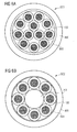
- Figure 2
- shows an embodiment of an optical transmission element including optical fibers being in contact with a sheath layer surrounding the optical fibers;
- Figure 3
- shows an embodiment of an optical transmission element including optical fibers being embedded in a material of a sheath layer surrounding the optical fibers;
- Figure 4
- shows an embodiment of an optical fiber;
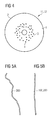
- Figure 5A
- illustrates a course of an embodiment of a single optical fiber pulled out of a core section of an optical transmission element;
- Figure 5B
- illustrates a course of an embodiment of an optical transmission element;
- Figure 6A
- illustrates an embodiment of a fiber optic cable comprising an optical transmission element;
- Figure 6B
- illustrates an embodiment of a fiber optic cable comprising optical transmission elements;
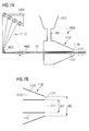
- Figure 7A
- illustrates an embodiment of an extruder for manufacturing an optical transmission element of a fiber optic cable;
- Figure 7B
- illustrates an embodiment of a nozzle of an extruder provided to manufacture an optical transmission element of a fiber optic cable.
-
Figure 1 shows an embodiment of anoptical transmission element 300 of a fiber optic cable comprisingoptical fibers sheath section 20. Asheath layer 21 of thesheath section 20 may be formed around thecore section 10 of the optical transmission element by an extrusion process. Thesheath layer 21 may be extruded in the form of a tube so that a free space is provided between the outeroptical fibers 12 being arranged adjacent to the inner surface of thesheath layer 21. - According to the embodiment of the
optical transmission element 300 theoptical fibers core section 10. The optical fibers may also be embedded in a gel. The gel may be disposed between the optical fibers and thesheath layer 21. Thesheath layer 21 is extruded with a distance in relation to at least some of the outer optical fibers being disposed in an outer area of the core section to avoid any pressure lateraly affecting theoptical fibers -
Figure 2 shows an embodiment of anoptical transmission element 100 of a fiber optic cable whereinoptical fibers core section 10 of the optical transmission element are encapsulated by asheath layer 21 of asheath section 20 of the optical transmission element. First inner ones of the optical fibers which are marked withreference number 11 are surrounded by second outer ones of the optical fibers which are marked withreference number 12. The outeroptical fibers 12 are positoned closer to thesheath layer 21, i.e. closer to the inner surface of thesheath layer 21, than the inneroptical fibers 11. The outer optical fibers are disposed so that no further one of the optical fibers is disposed between one of the outer optical fibers and the sheath layer. Thesheath layer 21 surrounds thecore section 10 such that all of the outeroptical fibers 12 being disposed in an outer area of the core section are in contact with thesheath layer 21. - Furthermore, the
sheath layer 21 exerts a force towards the optical fibers so that the optical fibers are also helt in contact with each other. Thesheath layer 21 is extruded tightly around the optical fibers such that the optical fibers are packed within the core section of the optical transmission element with high density so that each one of the optical fibers is in contact with at least two other ones of the optical fibers. The embodiment of theoptical transmission element 100 as illustrated inFigure 2 allows that theoptical fibers optical fibers 12 are in contact with the inner surface of thesheath layer 21. - The
optical fibers filler material 30, such as a gel. The gel prevents that forces exerted to thesheath layer 21 are directly transmitted to theoptical fibers - By way of example, the
sheath layer 21 may be extruded having an outer diameter of between 1,25 mm and 1,35 mm and having an inner diameter of between 1,0 and 1,05 mm. If twelve optical fibers are disposed within the core section as shown in the embodiment ofFigure 2 thesheath layer 21 is extruded around theoptical fibers core section 10 which is surrounded by the sheath layer. In the configuration as shown inFigure 2 the free space within the core section is for example reduced to 32 %. That means that the area of the cross section of thecore section 10 which is occupied by theoptical fibers core section 10 which is surrounded by the inner surface of thesheath layer 21. - The density by which the optical fibers are packed in the core section may also be characterized by the so called pull-out-force or tensile force which specifies a force which is necessary to pull out the whole optical fiber bundle out of the core section of the optical transmission element. According to the embodiment of the fiber optic cable shown in
Figure 1 the pull-out-force which is necessary to pull the whole bundle of the optical fibers out of a section of an optical transmission element having a length of 1 m is between 0,4 N to 0,5 N. That means that the twelve optical fibers shown inFigure 1 may be pulled out of the core section of the optical transmission element of the fiber optic cable by exerting a tensile force to the optical fibers which is between 0,4 N and 0,5 N. - In comparison to the low pull-out-force which is necessary to pull the optical fibers out of the core section of
Figure 1 the pull-out-force/tensile force which is needed to pull out optical fibers being configured in a high packing density is between 3 N to 10 N. According to the embodiment of the optical transmission element as shown inFigure 2 comprising twelve optical fibers the pull-out-force to pull the fibers out of the core section is 5 N. The embodiment of an optical transmission element comprising optical fibers which are coupled to each other and also coupled to the surroundingsheath layer 21 allows to transmit data signals such as light signals parallel via the optical fibers with a temporal skew of less than 2,5 ps/m. That means that the time delay between the data signals transferred via the different optical fibers of an optical transmission element is less than 2,5 ps if a data transmission is considered via the optical fibers of the optical transmission element of a length of 1 m. -
Figure 3 shows an embodiment of anoptical transmission element 200 of a fiber optic cable with optical fibers packed in thecore section 10 of the optical transmission element with a high density. The core section comprises twelve optical fibers. The optical fibers are arranged such that threeoptical fibers 11 are surrounded by nineoptical fibers 12 which is similar to the configuration of optical fibers as shown inFigure 2 . Asheath section 20 formed by asheath layer 21 surrounds thecore section 10 such that the fibers are in direct contact to each other and are also coupled to the material of thesheath layer 21. - The
sheath layer 21 may be formed around thecore section 10 by an extrusion process. As illustrated inFigure 3 , the sheath layer is extruded around theoptical fibers optical fibers 12 disposed closer to thesheath section 20 than the inneroptical fibers 11 are embedded in the material of thesheath layer 21. Thesheath layer 21 may be extruded around theoptical fibers - The core section may be formed in a dry configuration so that the optical fibers are in contact which each other and are not embedded in a filler material. According to another embodiment the
optical fibers sheath section 20 are transferred to the optical fibers. Furthermore, the gel has a water blocking capability so that in case of an ingress of water an expansion of water along the optical fibers within the core section is prevented. - According to the
embodiments sheath layer 21 may include a composition of material containing a mixture of ethyl methyl acetate, linear low density polyethylene, anorganic fillers and stabilizers. According to an embodiment of the fiber optic cable the mass ratio of the individual constituents of the material composition is 50 % of ethyl methyl acetate, 8 % of the linear low density polyethylene, 40 % of anorganic fillers, such as magnesium hydroxide or chalk, and an amount of approximately 2 % of stabilizers. The composition of material has a low melting temperature which is between 80° C to 90° C. Since the melting temperature of the material of the optical fibers is higher than the melting temperature of the material of the sheath layer, an adhering between the optical fibers and the sheath layer during the extrusion process is prevented. Furthermore, the material of the sheath layer has a low elongation at break of 6 MPa so that the sheath layer may be easily stripped, for example by bare fingers, to expose the optical fibers without using special tools. - The
optical fibers sheath layer 21. - According to a first embodiment of the optical fibers, the optical fibers may have a diameter of about 250 µm and contain a light guiding core region 1 and a
cladding region 2 surrounding the core region. The core region 1 and thecladding region 2 may be comprised of silica. The core region may also be silica doped with one or more dopants to provide a positive refractive index relative to pure silica. -
Figure 4 shows another embodiment of a fiber optic cable comprising microstructured optical fibers. According to the embodiment of the microstructured optical fibers, the core region 1 is hole-free whereas thecladding region 2 comprises an inner area 3 including a plurality of holes 5 and a hole-free outer area 4. The inner area 3 has for example a radial width which is not less than 0,5 µm and not larger than 20 µm. The hole-containing region may consist of undoped (pure) silica to achieve a decreased refractive index. The inner area 3 may also comprise doped silica, for example fluorine-doped silica, having a plurality of holes. The holes are for example stretched along the length, in a direction parallel to a longitudinal axis of the optical fiber, but do not extend the length of the entire fiber. The holes may include air or any other gas, for example an inert gas. The core region and the cladding region provide improved bend resistance so that the bend radius of the optical transmission element is down to 5 mm. -
Figure 5A shows a conventionaloptical transmission element 300 comprising optical fibers which are loosely arranged within a core section of the optical transmission element.Figure 5B shows an optical transmission element according to theembodiments Figure 5B are arranged within the core section of the optical transmission element in a straight manner so that microbendings between the individual optical fibers are significantly reduced in comparison to a loose arrangement of the optical fibers. - In contrast to the straight course of the optical transmission element of
Figure 5B , the optical fibers of the optical transmission element illustrated inFigure 5A has more bendings within the core section due to the loose arrangement of the optical fibers so that the optical transmission element ofFigure 5A shows a wave-shaped course. Due to the reduced microbendings of the optical fibers within the core section of the optical transmission element ofFigure 5B , the optical fibers have a fewer optical length variation and a fewer geometrical length variation in comparison to an optical transmission element wherein the optical fibers are loosely arranged so that a distance is provided between the optical fibers and the surrounding sheath layer. -
Figure 6A shows an embodiment of a fiber optic cable OC1 comprisingoptical transmission elements 100. According to the embodiment of the fiber optic cable shown inFigure 6A the cable comprises twelve optical transmission elements. The optical transmission elements are surrounded by athermoplastic cable jacket 400. A layer ofstrength member elements 500, such as yarns, is disposed between theoptical transmission elements 100 and the cable jacket. -
Figure 6B illustrates another embodiment of a fiber optic cable OC2.Optical transmission elements 100 are disposed around a centralstrength member element 700. A thin layer of anon-woven material 600 is disposed around theoptical transmission elements 100. The layer of the non-woven material may comprise water-swellable powder. Acable jacket 400 is extruded around the non-woven material. -
Figure 7A illustrates a production line for manufacturing the optical transmission element of the fiber optic cable. The optical fibers are provided rolled up on respective coils of astorage unit 2000. For reasons of simplicity, only four coils are shown inFigure 7A . In order to manufacture a fiber optic cable comprising optical transmission elements, as shown inFigure 2 and 3 , the production line comprises further eight coils on which the other optical fibers are stored. The optical fibers may be guided to anextruder 1000 via adeflection roller 3000. The optical fibers may be arranged in the core section of the optical transmission element in an unstranded manner. According to another embodiment of the fiber optic cable the optical fibers may be stranded in thestranding device 4000 and subsequently may be transported to theextruder 1000. - The
extruder 1000 comprises atank 1001 to heat a material provided for extruding around the core section of the optical transmission element. Thecore section 10 is formed by the optical fibers. After heating the thermoplastic material in thetank 1001 the melted material is transported via aconveyor 1002 to a conical-shapednozzle 1100 of the extruder. The nozzle comprises anopening 1111 through which theoptical fibers nozzle 1100 further comprises anopening 1121 to extrude the heated thermoplastic material around thecore section 10 of the optical transmission element. - The nozzle is configured so that the material of the sheath layer is extruded in contact with the optical fibers.
Figure 7B shows thenozzle 1100 of theextruder 1000 in an expandedview 1100 to illustrate the assembly and the dimesions of the individual components of the nozzle. - The nozzle comprises an
inner tube 1110 having a diameter DE1 and anouter tube 1120 surrounding the inner tube. Theouter tube 1120 is conically shaped. Theinner tube 1110 has anopening 1111 having a diameter DE1 through which the optical fibers are transported when the thermoplastic material stored in thetank 1001 is extruded around the core section of the optical transmission element. The diameter of theouter tube 1120 is larger than the diameter DE1 of theinner tube 1110. Theouter tube 1120 has anopening 1121 having a diameter DE2 so that a slit is formed between the the inner tube and the outer tube. - The optical fibers are guided within the
inner tube 1110 and leave the nozzle at theopening 1111. The material of the sheath layer is guided in anarea 1121 between the inner and the outer tube. In order to manufacture the optical transmission element so that the diameter of thesheath section 20 of the optical transmission element is small in a manner such that the optical fibers are packed in contact which each other within thecore section 10 and are also in contact with the material of thesheath layer 21 the relation between the diameter DE1 and the diameter DE2 is between 1,5 : 2,1 and 1,5 : 2,5. The nozzle may be provided for example with a diameter DE1 of theinner tube 1110 of 1,5 mm. Theouter tube 1120 may be provided with an opening having a diameter DE2 between 2,1 mm and 2,5 mm. - Another feature of the extruder may be obtained if a first quotient is formed between the diameter DE2 and the diameter DE1 and if a second quotient is formed between the outer diameter DT2 of the
sheath layer 21 and the diameter DT1 of the core section of the optical transmission element, as illustrated inFigure 2 . According to an embodiment of the nozzle, the diameter DE1 of theinner tube 1110 and the diameter DE2 of theopening 1121 of theouter tube 1120 of the extruder is determined so that a relation of the first quotient and the second quotient is bigger than 1,0, and preferably in a range of between 1,1 and 1,3. The relation of the first and section quotient is usually denoted as the so called draw balance. It has been found by the inventors that a relation of the draw balance in a range between 1,1 and 1,3 ensures that each of the optical fibers is coupled to at least two other ones of the optical fibers, and that the optical fibers are also coupled to the sheath layer when the sheath layer is extruded around the optical fibers. - The fiber optic cable which is manufactured by an extruder being configured with the dimension of the
inner tube 1110 and the dimension of the opening of theouter tube 1120 of thenozzle 1100 as specified above allows to manufacture a fiber optic cable comprising optical transmission elements comprising optical fibers, for example twelve optical fibers, which are included in a core section of each of the optical transmission elements of the fiber optic cable with a high packing density. Each of the optical fibers is in contact with at least two other ones of the optical fibers, and the outer optical fibers are in contract with the surrounding sheath layer so that microbendings of the optical fibers within the core section are avoided. The optical fibers of the optical transmission element have an optical length variation of less than 0,05 % per meter which leads to a skew of time delays of signals transmitted via the individual optical fibers packed within the core section of less than 2,5 ps per meter. A fiber optic cable comprising optical transmission elements according to the embodiments ofFigure 2 and 3 allows a high speed data transmission wherein bits are transmitted parallel via the individual optical fibers. The fiber optic cable is therefore especially suited to be used for connecting servers in data centers. - Although the present optical transmission element, the fiber optic cable and the method for manufacturing the fiber optic cable have been illustrated and described herein with reference to preferred embodiments and specific examples thereof, it will be readily apparent to those of ordinary skill in the art that other embodiments and examples can perform similar functions and/or achieve like results. All such equivalent embodiments and examples are within the spirit and scope of the present optical transmission element, the fiber optic cable and the method for manufacturing the fiber optic cable and are intended to be covered by the appended claims. It will also be apparent to those skilled in the art that various modifications and variations can be made to the present optical transmission element, the fiber optic cable and the method for manufacturing without departing from the spirit and scope of the optical transmission element, the fiber optic cable and the method to manufacture. Thus, it is intended that the present optical transmission element, the fiber optic cable and the method for manufacturing the fiber optic cable cover the modifications and variations of the optical transmission element, the fiber optic cable and the method for manufacturing provided they come within the scope of the appended claims and their equivalents.
Claims (15)
- A fiber optic cable (OC2), comprising:a central strength member (700);optical transmission elements (100) disposed around the central strength member (700), wherein the optical transmission elements (100) each comprise:optical fibers (11, 12) arranged within a core section (10) of the optical transmission elements (100), anda sheath layer (21) of a sheath section (20) of the optical transmission elements (100) encapsulating the optical fibers (11); wherein the optical fibers include inner optical fibers (11, 12) and outer optical fibers (12), which are positioned closer to the sheath layer (21) than the inner optical fibers (11); wherein all of the outer optical fibers (12) are in contact with the sheath layer (21); wherein the sheath layer is extruded tightly around the optical fibers (11, 12), which are packed within the core section (10) of the respective optical transmission element (100) with high density so that each one of the optical fibers (11, 12) is in contact with at least two others of the optical fibers (11, 12); wherein the sheath layer (21) exerts force toward the optical fibers (11, 12) so that the optical fibers (11, 12) are held in contact with each other and wherein the optical fibers (11, 12) are coupled by each other and are also coupled to the sheath layer (21); anda cable jacket (400) extruded around the optical transmission elements (100).
- The fiber optic cable (OC2) of claim 1, wherein the coupling is such that a tensile force to pull out the optical fibers (11, 12) as a whole bundle from the core section (10) of one of the optical transmission elements (100) is between 3 to 10 Newtons for a length of 1 meter of the respective optical transmission element (100).
- The fiber optic cable (OC2) of either claim 1 or 2, wherein the optical transmission elements (100) each include twelve optical fibers (11, 12), wherein the optical fibers (11, 12) have a diameter of about 250 micrometers, and wherein the sheath layer (21) has an inner diameter of between 1,0 and 1,05 millimeters.
- The fiber optic cable (OC2) of any one of claims 1 to 3, wherein the sheath layer (21) has an outer diameter of between 1,25 and 1,35 millimeters.
- The fiber optic cable (OC2) of any one of claims 1 to 4, wherein the sheath layer (21) is around the optical fibers (11, 12) such that free space of the cross-sectional area of the core section (10) that is not occupied by the optical fibers (11, 12) is between 30 to 40% of the total area of the cross-section of the core section (10).
- The fiber optic cable (OC2) of any one of claims 1 to 5, wherein the optical fibers (11, 12) of one of the optical transmission elements (100) have an optical length variation of less than 0,05 percent per meter which leads to a skew of time delays of signals transmitted via the individual optical fibers (11, 12) packed within the core section (10) of less than 2,5 picoseconds per meter.
- The fiber optic cable (OC2) of any one of claims 1 to 6, further comprising a material of chalk or a water-swellable material in the core section (10), whereby the core section (10) of each optical transmission element (100) is dry.
- The fiber optic cable (OC2) of any one of claims 1 to 6, further comprising a filler material (30) in the core section (10) that prevents forces exerted to the sheath layer (21) from being directly transmitted to the optical fibers (11, 12).
- The fiber optic cable (OC2) of any one of claims 1 to 8, wherein the sheath layer is formed from a thermoplastic.
- The fiber optic cable (OC2) of any one of claims 1 to 9, further comprising a layer of material (600) disposed around the optical transmission elements (100), wherein the layer of material (600) comprises water-swellable powder and wherein cable jacket (400) is extruded around the layer of material (600).
- A method of manufacturing the fiber optic cable (OC2) of any one of claims 1 to 10 comprising a step of guiding optical fibers to an extruder (1000) via a deflection roller (3000).
- The method of claim 11, further comprising steps of heating the thermoplastic material and transporting the thermoplastic material to the extruder (1000) to extrude the heated thermoplastic material around the core section (10) of the respective optical transmission element (100).
- The method of claim 12, wherein a draw balance of the thermoplastic material is in a range between 1,1 and 1,3, which ensures each of the optical fibers (11, 12) is coupled to at least two other ones of the optical fibers (11, 12) and that the optical fibers (11, 12) are also coupled to the sheath layer (21).
- The method of either claim 12 or 13, wherein the extruder (1000) includes a conical-shaped nozzle (1100), wherein the nozzle (1100) comprises an opening (1111) through which the optical fibers (11, 12) are transported, and wherein the nozzle (1100) further comprises an opening (1121) to extrude the heated thermoplastic material around the core section (10) of each optical transmission element (100).
- The method of claim 14, wherein the nozzle more specifically comprises an inner tube (1110) having a diameter (DE1) and an outer tube (1120) surrounding the inner tube (1110), and wherein the outer tube (1120) is conically shaped, and wherein the inner tube (1110) has the opening (1111) having the diameter (DE1) through which the optical fibers (11, 12) are transported when the thermoplastic material is extruded around the core section (10) of the optical transmission elements (100), and wherein a diameter (DE2) of the outer tube (1120) is larger than the diameter (DE1) of the inner tube (1110), and wherein the ratio of the diameter (DE1) of the inner tube (1110) to the diameter (DE2) of the outer tube (1120) is between 1,5:2,1 and 1,5:2,5.
Priority Applications (1)
| Application Number | Priority Date | Filing Date | Title |
|---|---|---|---|
| EP14160691.3A EP2778731A1 (en) | 2009-06-22 | 2009-06-22 | Fiber optic cable |
Applications Claiming Priority (2)
| Application Number | Priority Date | Filing Date | Title |
|---|---|---|---|
| EP14160691.3A EP2778731A1 (en) | 2009-06-22 | 2009-06-22 | Fiber optic cable |
| EP09163404A EP2267505A1 (en) | 2009-06-22 | 2009-06-22 | Bundle of optical fibres for use in a fibre optic cable |
Related Parent Applications (1)
| Application Number | Title | Priority Date | Filing Date |
|---|---|---|---|
| EP09163404A Division EP2267505A1 (en) | 2009-06-22 | 2009-06-22 | Bundle of optical fibres for use in a fibre optic cable |
Publications (1)
| Publication Number | Publication Date |
|---|---|
| EP2778731A1 true EP2778731A1 (en) | 2014-09-17 |
Family
ID=41262224
Family Applications (2)
| Application Number | Title | Priority Date | Filing Date |
|---|---|---|---|
| EP09163404A Ceased EP2267505A1 (en) | 2009-06-22 | 2009-06-22 | Bundle of optical fibres for use in a fibre optic cable |
| EP14160691.3A Withdrawn EP2778731A1 (en) | 2009-06-22 | 2009-06-22 | Fiber optic cable |
Family Applications Before (1)
| Application Number | Title | Priority Date | Filing Date |
|---|---|---|---|
| EP09163404A Ceased EP2267505A1 (en) | 2009-06-22 | 2009-06-22 | Bundle of optical fibres for use in a fibre optic cable |
Country Status (3)
| Country | Link |
|---|---|
| US (1) | US8630520B2 (en) |
| EP (2) | EP2267505A1 (en) |
| CN (1) | CN101957483B (en) |
Families Citing this family (6)
| Publication number | Priority date | Publication date | Assignee | Title |
|---|---|---|---|---|
| CN102549466B (en) * | 2009-09-28 | 2016-06-22 | 普睿司曼股份公司 | optical communication cable and manufacturing process |
| MX2016016461A (en) * | 2014-06-23 | 2017-04-06 | Corning Optical Communications LLC | OPTICAL FIBER CABLE. |
| US9921381B2 (en) * | 2016-02-03 | 2018-03-20 | Ofs Fitel, Llc | Loose-tube optical fiber cables |
| EP3911981B1 (en) * | 2019-01-19 | 2026-02-18 | Corning Research & Development Corporation | Unitized fiber optic cables |
| US12013585B2 (en) | 2021-01-26 | 2024-06-18 | Apple Inc. | Electronic devices with optical fiber ribbons |
| WO2025059410A1 (en) * | 2023-09-15 | 2025-03-20 | Corning Research & Development Corporation | Optical fiber cable exhibiting low skew |
Citations (5)
| Publication number | Priority date | Publication date | Assignee | Title |
|---|---|---|---|---|
| US4414165A (en) * | 1981-03-26 | 1983-11-08 | Siemens Aktiengesellschaft | Method and device for producing an optical transmission element |
| GB2262996A (en) * | 1991-12-19 | 1993-07-07 | Siemens Ag | Optical waveguide cable having reinforced covering formed by coextrusion |
| EP1018662A2 (en) * | 1999-01-07 | 2000-07-12 | Alcatel | Optical cable |
| EP1434074A1 (en) * | 2002-12-23 | 2004-06-30 | Corning Cable Systems | High density fiber optic cable with easy open sub-units |
| EP2163927A1 (en) * | 2008-09-12 | 2010-03-17 | CCS Technology Inc. | Optical cable with stranded micromodules and apparatus to manufacture the optical cable |
Family Cites Families (9)
| Publication number | Priority date | Publication date | Assignee | Title |
|---|---|---|---|---|
| US6853780B1 (en) * | 1999-03-31 | 2005-02-08 | Pirelli Cavi E Sistemi S.P.A. | Optical cable for telecommunications |
| DE10165020B4 (en) * | 2001-06-20 | 2009-04-23 | CCS Technology, Inc., Wilmington | Optical transmission element |
| DE10129772B4 (en) * | 2001-06-20 | 2007-10-11 | CCS Technology, Inc., Wilmington | Optical transmission element |
| US6901191B2 (en) * | 2001-11-12 | 2005-05-31 | Corning Cable Systems Llc | High density fiber optic cable |
| GB0313018D0 (en) * | 2002-08-10 | 2003-07-09 | Emtelle Uk Ltd | Signal transmitting cable |
| GB0313017D0 (en) * | 2002-08-10 | 2003-07-09 | Emtelle Uk Ltd | Signal transmitting cable |
| DE102006018536A1 (en) * | 2006-04-21 | 2007-10-25 | CCS Technology, Inc., Wilmington | Optical cable and method of making an optical cable |
| US7397991B1 (en) * | 2006-12-13 | 2008-07-08 | Corning Cable Systems Llc | Fiber optic cables and assemblies and the performance thereof |
| US8074596B2 (en) * | 2007-04-30 | 2011-12-13 | Corning Cable Systems Llc | Apparatus for forming a sheath over an elongate member, extruder system and method of manufacturing a fiber optic cable |
-
2009
- 2009-06-22 EP EP09163404A patent/EP2267505A1/en not_active Ceased
- 2009-06-22 EP EP14160691.3A patent/EP2778731A1/en not_active Withdrawn
-
2010
- 2010-06-18 US US12/819,104 patent/US8630520B2/en active Active
- 2010-06-22 CN CN201010211412.1A patent/CN101957483B/en not_active Expired - Fee Related
Patent Citations (5)
| Publication number | Priority date | Publication date | Assignee | Title |
|---|---|---|---|---|
| US4414165A (en) * | 1981-03-26 | 1983-11-08 | Siemens Aktiengesellschaft | Method and device for producing an optical transmission element |
| GB2262996A (en) * | 1991-12-19 | 1993-07-07 | Siemens Ag | Optical waveguide cable having reinforced covering formed by coextrusion |
| EP1018662A2 (en) * | 1999-01-07 | 2000-07-12 | Alcatel | Optical cable |
| EP1434074A1 (en) * | 2002-12-23 | 2004-06-30 | Corning Cable Systems | High density fiber optic cable with easy open sub-units |
| EP2163927A1 (en) * | 2008-09-12 | 2010-03-17 | CCS Technology Inc. | Optical cable with stranded micromodules and apparatus to manufacture the optical cable |
Also Published As
| Publication number | Publication date |
|---|---|
| CN101957483B (en) | 2016-03-02 |
| CN101957483A (en) | 2011-01-26 |
| US20100322574A1 (en) | 2010-12-23 |
| EP2267505A1 (en) | 2010-12-29 |
| US8630520B2 (en) | 2014-01-14 |
Similar Documents
| Publication | Publication Date | Title |
|---|---|---|
| US8750661B2 (en) | Optical fiber assemblies having a powder or powder blend at least partially mechanically attached | |
| US6714710B2 (en) | Fiber optic cables with strength members | |
| US6785450B2 (en) | Self-supporting fiber optic cable | |
| EP2946238B1 (en) | Fiber optic ribbon cable | |
| US10663683B2 (en) | Optical fiber bundle | |
| US8630520B2 (en) | Optical transmission element | |
| EP1160606A2 (en) | Method and apparatus for producing a solid-stranded flextube unit | |
| EP1895340A1 (en) | A loose tube optical waveguide fiber cable | |
| US20230213716A1 (en) | Ribbed and grooved sheath for optical fiber cable | |
| US20160266342A1 (en) | Optical fiber bundle | |
| WO2001084206A2 (en) | Fiber optic cable | |
| US6654526B2 (en) | Use of water swellable yarns and particles in gel compound-filled buffer tubes and uniribbon fiber optic cables | |
| EP4579304A1 (en) | Optical fiber cable with multifibre tight-buffered unit | |
| AU2009277178B2 (en) | Optical fiber assemblies having a powder or powder blend at least partially mechanically attached | |
| CN110600178A (en) | Optical communication cable bundle | |
| HK1165561A (en) | Optical fiber assemblies having a powder or powder blend at least partially mechanically attached |
Legal Events
| Date | Code | Title | Description |
|---|---|---|---|
| 17P | Request for examination filed |
Effective date: 20140319 |
|
| AC | Divisional application: reference to earlier application |
Ref document number: 2267505 Country of ref document: EP Kind code of ref document: P |
|
| AK | Designated contracting states |
Kind code of ref document: A1 Designated state(s): AT BE BG CH CY CZ DE DK EE ES FI FR GB GR HR HU IE IS IT LI LT LU LV MC MK MT NL NO PL PT RO SE SI SK TR |
|
| PUAI | Public reference made under article 153(3) epc to a published international application that has entered the european phase |
Free format text: ORIGINAL CODE: 0009012 |
|
| RIN1 | Information on inventor provided before grant (corrected) |
Inventor name: WUENSCH, GUENTER Inventor name: MERBACH, GERHARD Inventor name: STOECKLEIN, WALDEMAR |
|
| R17P | Request for examination filed (corrected) |
Effective date: 20150310 |
|
| RBV | Designated contracting states (corrected) |
Designated state(s): AT BE BG CH CY CZ DE DK EE ES FI FR GB GR HR HU IE IS IT LI LT LU LV MC MK MT NL NO PL PT RO SE SI SK TR |
|
| 17Q | First examination report despatched |
Effective date: 20180808 |
|
| RAP1 | Party data changed (applicant data changed or rights of an application transferred) |
Owner name: CORNING OPTICAL COMMUNICATIONS LLC |
|
| RAP1 | Party data changed (applicant data changed or rights of an application transferred) |
Owner name: CORNING OPTICAL COMMUNICATIONS LLC |
|
| STAA | Information on the status of an ep patent application or granted ep patent |
Free format text: STATUS: THE APPLICATION IS DEEMED TO BE WITHDRAWN |
|
| 18D | Application deemed to be withdrawn |
Effective date: 20200804 |