EP2778702A2 - Battery meter and power tool including battery meter - Google Patents
Battery meter and power tool including battery meter Download PDFInfo
- Publication number
- EP2778702A2 EP2778702A2 EP14158236.1A EP14158236A EP2778702A2 EP 2778702 A2 EP2778702 A2 EP 2778702A2 EP 14158236 A EP14158236 A EP 14158236A EP 2778702 A2 EP2778702 A2 EP 2778702A2
- Authority
- EP
- European Patent Office
- Prior art keywords
- announcement
- remaining capacity
- rechargeable battery
- power
- capacity information
- Prior art date
- Legal status (The legal status is an assumption and is not a legal conclusion. Google has not performed a legal analysis and makes no representation as to the accuracy of the status listed.)
- Granted
Links
Images




Classifications
-
- H—ELECTRICITY
- H01—ELECTRIC ELEMENTS
- H01M—PROCESSES OR MEANS, e.g. BATTERIES, FOR THE DIRECT CONVERSION OF CHEMICAL ENERGY INTO ELECTRICAL ENERGY
- H01M10/00—Secondary cells; Manufacture thereof
- H01M10/42—Methods or arrangements for servicing or maintenance of secondary cells or secondary half-cells
- H01M10/48—Accumulators combined with arrangements for measuring, testing or indicating the condition of cells, e.g. the level or density of the electrolyte
- H01M10/488—Cells or batteries combined with indicating means for external visualization of the condition, e.g. by change of colour or of light density
-
- G—PHYSICS
- G01—MEASURING; TESTING
- G01R—MEASURING ELECTRIC VARIABLES; MEASURING MAGNETIC VARIABLES
- G01R31/00—Arrangements for testing electric properties; Arrangements for locating electric faults; Arrangements for electrical testing characterised by what is being tested not provided for elsewhere
- G01R31/36—Arrangements for testing, measuring or monitoring the electrical condition of accumulators or electric batteries, e.g. capacity or state of charge [SoC]
- G01R31/385—Arrangements for measuring battery or accumulator variables
- G01R31/387—Determining ampere-hour charge capacity or SoC
- G01R31/388—Determining ampere-hour charge capacity or SoC involving voltage measurements
-
- G—PHYSICS
- G01—MEASURING; TESTING
- G01R—MEASURING ELECTRIC VARIABLES; MEASURING MAGNETIC VARIABLES
- G01R31/00—Arrangements for testing electric properties; Arrangements for locating electric faults; Arrangements for electrical testing characterised by what is being tested not provided for elsewhere
- G01R31/36—Arrangements for testing, measuring or monitoring the electrical condition of accumulators or electric batteries, e.g. capacity or state of charge [SoC]
- G01R31/3644—Constructional arrangements
- G01R31/3646—Constructional arrangements for indicating electrical conditions or variables, e.g. visual or audible indicators
-
- G—PHYSICS
- G01—MEASURING; TESTING
- G01R—MEASURING ELECTRIC VARIABLES; MEASURING MAGNETIC VARIABLES
- G01R31/00—Arrangements for testing electric properties; Arrangements for locating electric faults; Arrangements for electrical testing characterised by what is being tested not provided for elsewhere
- G01R31/36—Arrangements for testing, measuring or monitoring the electrical condition of accumulators or electric batteries, e.g. capacity or state of charge [SoC]
- G01R31/3644—Constructional arrangements
- G01R31/3648—Constructional arrangements comprising digital calculation means, e.g. for performing an algorithm
-
- H—ELECTRICITY
- H01—ELECTRIC ELEMENTS
- H01M—PROCESSES OR MEANS, e.g. BATTERIES, FOR THE DIRECT CONVERSION OF CHEMICAL ENERGY INTO ELECTRICAL ENERGY
- H01M2220/00—Batteries for particular applications
- H01M2220/30—Batteries in portable systems, e.g. mobile phone, laptop
-
- H—ELECTRICITY
- H01—ELECTRIC ELEMENTS
- H01M—PROCESSES OR MEANS, e.g. BATTERIES, FOR THE DIRECT CONVERSION OF CHEMICAL ENERGY INTO ELECTRICAL ENERGY
- H01M50/00—Constructional details or processes of manufacture of the non-active parts of electrochemical cells other than fuel cells, e.g. hybrid cells
- H01M50/20—Mountings; Secondary casings or frames; Racks, modules or packs; Suspension devices; Shock absorbers; Transport or carrying devices; Holders
- H01M50/247—Mountings; Secondary casings or frames; Racks, modules or packs; Suspension devices; Shock absorbers; Transport or carrying devices; Holders specially adapted for portable devices, e.g. mobile phones, computers, hand tools or pacemakers
-
- Y—GENERAL TAGGING OF NEW TECHNOLOGICAL DEVELOPMENTS; GENERAL TAGGING OF CROSS-SECTIONAL TECHNOLOGIES SPANNING OVER SEVERAL SECTIONS OF THE IPC; TECHNICAL SUBJECTS COVERED BY FORMER USPC CROSS-REFERENCE ART COLLECTIONS [XRACs] AND DIGESTS
- Y02—TECHNOLOGIES OR APPLICATIONS FOR MITIGATION OR ADAPTATION AGAINST CLIMATE CHANGE
- Y02E—REDUCTION OF GREENHOUSE GAS [GHG] EMISSIONS, RELATED TO ENERGY GENERATION, TRANSMISSION OR DISTRIBUTION
- Y02E60/00—Enabling technologies; Technologies with a potential or indirect contribution to GHG emissions mitigation
- Y02E60/10—Energy storage using batteries
Definitions
- the present invention relates to a battery meter, which announces the remaining capacity of a rechargeable battery, and a power tool including a battery meter.
- Japanese Laid-Open Patent Publication No. 7-192772 describes a method for indicating the remaining capacity of a rechargeable battery.
- the method includes a process for correcting an estimation error of the remaining capacity of the rechargeable battery when using a large current.
- the remaining capacity is calculated from an accumulated value of the discharge current and the battery voltage.
- the battery voltage decreases to a set voltage, a correction is made to the remaining capacity that is calculated with the battery voltage.
- Japanese Laid-Open Patent Publication No. 2007-139549 describes a method for measuring the remaining capacity of a rechargeable battery.
- the method includes a remaining capacity computation process performed in correspondence with different situations, namely, before an electrical load is supplied with power (i.e., when power is not supplied), when the electrical load is supplied with power, and after the electrical load is supplied with power.
- the inventors of the present invention have noticed that during usage of the rechargeable battery, the computation result of the remaining capacity deviates greatly from the actual remaining capacity. Thus, for example, when the rechargeable battery is supplying a large current to the electrical load, it would be difficult to accurately estimate the remaining capacity of the rechargeable battery.
- an electric instrument may indicate that the remaining capacity of the rechargeable battery is low even though the actual remaining capacity is high enough to permit discharging of the rechargeable battery. Such an incorrect indication would prompt the user of the electric instrument to replace the rechargeable battery.
- an electric instrument may indicate that the remaining capacity of the rechargeable battery is sufficient even though the actual remaining capacity is low such that discharging of the rechargeable battery should be prohibited. Such an incorrect indication would result in the user continuing the use of the electric instrument. This would lead to over-discharging of the rechargeable battery.
- the battery meter includes a voltage measurement unit for measuring an inter-terminal voltage of the rechargeable battery, an announcement unit for announcing rechargeable battery remaining capacity information based on the measurement of the inter-terminal voltage, and an announcement request switch for outputting an announcement request for requesting announcement of the remaining capacity information.
- the announcement unit is configured to announce the remaining capacity information when the announcement request is received during a period in which the electrical load is not supplied with power, and not announce the remaining capacity information regardless of whether or not the announcement request is received during a period in which the electrical load is supplied with power.
- the announcement unit is configured to generate the remaining capacity information when the announcement request is received during a period in which the electrical load is not supplied with power, and announce the remaining capacity information, which is generated when the announcement request is received, throughout a set announcement period even when the inter-terminal voltage changes after the announcement request is received.
- the announcement unit includes a recovery prediction function or a recovery prediction map for predicting recovery of the inter-terminal voltage when the supply of power to the electrical load is stopped. Further, the announcement unit is configured to predict a recovered inter-terminal voltage with the recovery prediction function or the recovery prediction map when the supply of power to the electrical load is stopped, and generate the rechargeable battery remaining capacity information based on the prediction of the recovered inter-terminal voltage.
- the announcement unit interrupts the announcement of the rechargeable battery remaining capacity information.
- the announcement unit includes an indicator that visually indicates the rechargeable battery remaining capacity information.
- the announcement unit includes a voice generator that generates a voice to announce the rechargeable battery remaining capacity information.
- the electrical load is the motor.
- a further aspect of the present invention is a power tool including an electrical load and the aforementioned battery meter.
- Fig. 1 shows a chargeable drill driver, which is one example of the power tool 1.
- the power tool 1 includes a tool main body 2 and a battery pack 3, which is attached to the tool main body 2 in a removable manner.
- the tool main body 2 includes a housing 10 and an electric circuit 20, which is accommodated in the housing 10 (refer to Fig. 2 ).
- the housing 10 includes a barrel 11, a chuck 12, and a grip 13.
- the electric circuit 20 is accommodated in, for example, the barrel 11.
- the chuck 12 holds a removable tool bit (e.g., drill).
- a trigger lever 14 is coupled to, for example, an upper portion 13a of the grip 13 near the barrel 11.
- the trigger lever 14 is used to set the torque applied to the tool bit (e.g., drill). The torque is increased in accordance with the pulled amount of the trigger lever 14.
- a spring may be used to outwardly urge the trigger lever 14 from the grip 13.
- the trigger lever 14 is pulled into the grip 13 when operated.
- the trigger lever 14 outputs a trigger signal Str having a level that is in accordance with the pulled amount.
- the pulled amount is, for example, the movement distance of the trigger lever 14 when the trigger lever 14 is pulled.
- the grip 13 includes a lower portion 13b (side farther from the barrel 11) and a middle portion 13c.
- the lower portion 13b is wider than the middle portion 13c.
- the lower portion 13b of the grip 13 includes a lower surface, to which a battery pack 3 is attached in a removable manner, and an upper surface, on which an indicator 27b and an announcement request switch 28 are arranged.
- the indicator 27b includes, for example, three light emitting diodes (LEDs), namely, first to third LEDs 271 to 273.
- LEDs light emitting diodes
- the first to third LEDs 271 to 273 are arranged in a single line.
- the announcement request switch 28 is operated by the user of the power tool 1.
- the announcement request switch 28 may be, for example, a push button that is moved in a pushing direction to a pushed position when pushed and returned to an original normal position when released.
- the battery pack 3 incorporates a rechargeable battery 30.
- the rechargeable battery 30 may be any rechargeable battery cell, such as a lithium-ion rechargeable battery, a lithium rechargeable battery, or a nickel-metal hydride battery.
- the battery pack 3, or the rechargeable battery 30, includes a positive electrode 32 and a negative electrode 33 that are configured to be connectable to the electric circuit 20 of the power tool 1.
- the rechargeable battery 30 includes one or more battery cells 31. In the illustrated example, the battery cells 31 are connected in series.
- the electric circuit 20 of the power tool includes a circuit main body 21 and a battery meter 25.
- the circuit main body 21 includes a motor 22 (electric motor), a drive circuit 23, and a main body control unit 24.
- the motor 22 is a driving device that rotates the tool bit (e.g., drill). In comparison with the drive circuit 23 and the main body control unit 24, the motor 22 consumes a large amount of power.
- the power supplied from the rechargeable battery 30 is mainly consumed by the motor 22.
- the motor 22 substantially acts as the main electrical load of the rechargeable battery 30 and is referred to as the electrical load that most dominantly affects the estimation of the remaining capacity C.
- the main body control unit 24 receives the trigger signal Str, generates a control signal for controlling the motor 22 in accordance with the level of the trigger signal Str, and provides the control signal to the drive circuit 23.
- the control signal may be a pulse width modulation (PWM) signal.
- the drive circuit 23 supplies the motor 22 with power that is in accordance with the control signal received from the main body control unit 24.
- the main body control unit 24 determines whether or not power is supplied to the motor 22 based on, for example, the level of the trigger signal Str from the trigger lever 14, the amount of current supplied to the motor 22, or the rotation speed of the motor 22.
- the main body control unit 24 provides an announcement unit 27 with a power supply determination signal SX indicating that the motor 22 is being supplied with power.
- the main body control unit 24 receives an announcement request signal SC from the announcement request switch 28 and transmits the announcement request SC to the announcement unit 27.
- the announcement request switch 28 directly provides the announcement request SC to the announcement unit 27 and does not transmit the announcement request SC via the main body control unit 24.
- the battery meter 25 includes a voltage measurement unit 26, the announcement unit 27, and the announcement request switch 28.
- the voltage measurement unit 26 measures the potential difference between a positive terminal 29a and a negative terminal 29b of the electric circuit 20 and provides the main body control unit 24 with a measurement signal indicating the potential difference.
- the potential difference between the positive terminal 29a and the negative terminal 29b corresponds to the inter-terminal voltage Vt of the rechargeable battery 30.
- the positive terminal 29a is connected to the positive electrode 32 of the battery pack 3, or the rechargeable battery 30.
- the negative terminal 29b is connected to the negative electrode 33 of the battery pack 3, or the rechargeable battery 30.
- the announcement request switch 28 is operated by the user of the power tool 1. When operated, the announcement request switch 28 sends an announcement request SC to the announcement unit 27 to request the announcement unit 27 to announce information related to the rechargeable battery remaining capacity C (hereinafter, referred to as the remaining capacity information). For example, the announcement request switch 28 provides the main body control unit 24 with the announcement request SC when pushed and does not output the announcement request
- the announcement unit 27 includes an announcement controller 27a and the indicator 27b. Based on the announcement request SC and the power supply determination signal SX, the announcement controller 27a determines whether or not to indicate the remaining capacity information of the rechargeable battery 30 with the indicator 27b. When determining to announce the remaining capacity information of the rechargeable battery 30, the announcement controller 27a indicates the remaining capacity information on the indicator 27b.
- the indicator 27b indicates the remaining capacity information.
- the announcement controller 27a controls the lighting of the first to third LEDs 271 to 273.
- the announcement controller 27a activates or deactivates each of the first to third LEDs 271 to 273 in accordance with the rechargeable battery remaining capacity C.
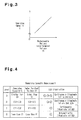
- Fig. 3 shows the relationship of the inter-terminal voltage V of the rechargeable battery 30 and the rechargeable battery remaining capacity C when the discharge current of the rechargeable battery 30 is substantially zero.
- the rechargeable battery remaining capacity C decrease as the inter-terminal voltage Vt of the rechargeable battery 30 decreases. This allows the main body control unit 24 to estimate the rechargeable battery remaining capacity C based on the inter-terminal voltage Vt of the rechargeable battery 30.
- Fig. 4 is a table showing an indication example of the rechargeable battery remaining capacity C.
- the rechargeable battery remaining capacity C is less than capacity C1 (level 0). In this case, the first LED 271 is intermittently illuminated.
- the rechargeable battery remaining capacity C is greater than or equal to capacity C1 and less than capacity C2 (level 1).
- the first LED 271 is continuously illuminated.
- the rechargeable battery remaining capacity C is greater than or equal to capacity C2 and less than capacity C3 (level 2).
- the first and second LEDs 271 and 272 are continuously illuminated.
- the rechargeable battery remaining capacity C is greater than or equal to capacity C3 (level 3).
- the first to third LEDs 271 to 273 are continuously illuminated.
- Fig. 5 shows changes in the inter-terminal voltage Vt of the rechargeable battery 30 when the supply of power to the motor 22 is started.
- the user operates the trigger lever 14 to start the supply of power to the motor 22.
- the inter-terminal voltage Vt of the rechargeable battery 30 decreases temporarily and rapidly increases to show an extreme drop. Thereafter, the inter-terminal voltage Vt of the rechargeable battery 30 gradually and slightly increases as power is continuously consumed by the motor 22.
- Fig. 6 shows changes in the inter-terminal voltage Vt of the rechargeable battery 30 when the supply of power to the motor 22 is stopped.
- the user releases the trigger lever 14 and stops the supply of power to the motor 22.
- This gradually and slightly increases the inter-terminal voltage Vt of the rechargeable battery 30.
- the slight voltage increase occurs because the discharge current is large when the motor 22 operates, the voltage drop caused by the internal resistance of the rechargeable battery 30 is large, and the estimated or measured inter-terminal voltage Vt (measured value) is lower than the inter-terminal voltage (true value) corresponding to the actuator remaining capacity Cr.
- the inter-terminal voltage (measured value) of the rechargeable battery 30 during operation of the motor 22 is lower than the inter-terminal voltage (true value) corresponding to the actual rechargeable battery remaining capacity Cr. Further, the voltage difference between the inter-terminal voltage Vt (measured value) of the rechargeable battery 30 during operation of the motor 22 and the inter-terminal voltage (true value) corresponding to the actual rechargeable battery remaining capacity Cr is large such that it cannot be ignored when estimating the rechargeable battery remaining capacity C.
- the estimated value when estimating the rechargeable battery remaining capacity C based on the inter-terminal voltage Vt of the rechargeable battery 30 measured during operation of the motor 22, the estimated value would be lower than the actual rechargeable battery remaining capacity Cr. The low estimated value would lead to the following problem during usage of the power tool 1.
- the user would replace the battery pack 3 with another battery pack.
- the rechargeable battery remaining capacity C when the power tool 1 is operating is indicated as being lower than the actual rechargeable battery remaining capacity Cr.
- the user would be replacing the battery pack 3 based on an incorrect estimation result of the rechargeable battery remaining capacity.
- the battery pack 3 may be replaced even though the battery pack 3 can still be used. In this manner, even though the battery pack 3 is still usable, the user would replace the battery pack 3. This increases the number of times the battery pack 3 is replaced. Further, the user would erroneously believe that the power loss is large in the power tool 1, and the frequent battery pack replacement would be inconvenient for the user.
- the power tool 1 of the present embodiment performs a process that stops the indication of the rechargeable battery remaining capacity C when the motor 22 is operating.
- a process that stops the indication of the rechargeable battery remaining capacity C when the motor 22 is operating.
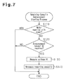
- the announcement unit 27 performs the remaining capacity announcement starting process in predetermined cycles.
- step S110 the announcement controller 27a determines whether or not the motor 22 is being supplied with power. The determination is based on the power supply determination signal SX from the main body control unit 24. For example, when receiving the power supply determination signal SX, the announcement controller 27a determines that the motor 22 is being supplied with power. When the power supply determination signal SX is not received, the announcement controller 27a determines that the motor 22 is not being supplied with power.
- the announcement controller 27a ends the remaining capacity announcement starting process.
- step S120 the announcement controller 27a determines whether or not the announcement request SC has been received.
- the announcement controller 27a ends the remaining capacity announcement starting process.
- step S130 the announcement controller 27a measures the inter-terminal voltage Vt of the rechargeable battery 30.
- step S140 the announcement controller 27a generates the remaining capacity information based on the measured inter-terminal voltage Vt and announces the remaining capacity information.
- the remaining capacity information indicates the level of the rechargeable battery remaining capacity C.
- the remaining capacity information is indicated based on the level of the rechargeable battery remaining capacity C shown in the row at the left end of Fig. 4 .
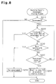
- the announcement unit 27 performs the remaining capacity announcement stopping process while announcing the rechargeable battery remaining capacity C.
- step S210 the announcement unit 27 determines whether or not the remaining capacity information is being announced. When the remaining capacity information is not being announced (NO in step S210), the announcement unit 27 ends the remaining capacity announcement stopping process.
- the announcement unit 27 may be configured not to perform the remaining capacity announcement stopping process when the remaining capacity information is not being announced.
- step S220 the announcement unit 27 determines whether or not the announcement time of the remaining capacity information is longer than a predetermined set announcement period Tx.
- the set announcement period Tx is set to be long enough to allow the user to acknowledge the remaining capacity information.
- the announcement unit 27 stops the announcement of the remaining capacity information. Under normal situations, the remaining capacity information is announced throughout the set announcement period Tx.
- the remaining capacity information which is set during step S 140 during the remaining capacity announcement starting process, is continuously announced without being changed until the set announcement period Tx ends or an announcement stopping command is received.
- step S230 the announcement unit 27 determines whether or not power is being supplied to the motor 22. For example, when the power supply determination signal SX is received from the main body control unit 24, the announcement controller 27a determines that the motor 22 is being supplied with power.
- step S250 the announcement unit 27 stops the announcement of the remaining capacity information. As described above, the announcement is stopped because the estimation accuracy of the rechargeable battery remaining capacity C, which is based on the inter-terminal voltage Vt, is low when power is being supplied to the motor 22.
- step S240 the announcement unit 27 determines whether or not an announcement request SC has been received.
- the announcement unit 27 returns to step S220.
- step S260 the announcement unit 27 performs the remaining capacity announcement starting process.
- the remaining capacity announcement starting process is started, the previous announcement time and the previous remaining capacity information are reset or initialized, and the announcement time and the inter-terminal voltage Vt are measured from the beginning.
- the remaining capacity announcement stopping process is terminated.
- the announcement of the remaining capacity information is continued throughout the set announcement period Tx. However, when the motor 22 is supplied with power during the announcement of the remaining capacity information, the announcement is interrupted. When a new announcement request SC is received during the announcement of the remaining capacity information, the remaining capacity announcement starting process is performed as long as the motor 22 is not supplied with power.
- Time t11 in Fig. 9 indicates the timing in which the announcement unit 27 receives the announcement request SC when the motor 22 is not being supplied with power.
- the remaining capacity announcement starting process indicates the remaining capacity information of the rechargeable battery 30 with the indicator 27b. For example, when the inter-terminal voltage Vt of the rechargeable battery 30 is higher than or equal to voltage V3, the first to third LEDs 271 to 273 are continuously illuminated. The remaining capacity information is indicated during the period from time t11 to time t12, which is when the set announcement period Tx ends.
- the supply of power to the motor 22 starts.
- the announcement unit 27 receives an announcement request SC when the motor 22 is being supplied with power.
- the indicator 27b does not indicate the remaining capacity information of the rechargeable battery 30 even though the announcement request SC has been received. Accordingly, the first to third LEDs 271 to 273 remain deactivated.
- the announcement unit 27 receives an announcement request SC.
- the remaining capacity announcement starting process indicates the remaining capacity information of the rechargeable battery 30 with the indicator 27b.
- Time t22 the supply of power to the motor 22 is started. Time t22 is before the set announcement period Tx ends, or before t23. However, the determination of step S230 in the remaining capacity announcement stopping process interrupts the indication of the remaining capacity information. In this manner, when the motor 22 is supplied with power, the remaining capacity information of the rechargeable battery 30 is not indicated.
- the announcement request switch 28 is pushed, and the announcement request SC is provided to the announcement unit 27.
- the period between time t32 and time t33 and the period between time t33 and time t34 are shorter than the set announcement period Tx.
- the inter-terminal voltage Vt of the rechargeable battery 30 may gradually increase.
- the remaining capacity information indicated by the indicator 27b is updated at time t32, time t33, and time t34.
- the inter-terminal voltage Vt measured at time t32, time t33, and time t34 may be voltage V11, voltage V12, and voltage V13, respectively.
- voltage V11 and voltage V12 may be between voltage V2 and voltage V3 in the table of Fig. 4
- voltage V13 may be higher than or equal to voltage V3 in the table of Fig. 4 .
- the indicator 27b continuously illuminates two LEDs, namely, the first LED 271 and the second LED 272. Then, the indicator 27b continuously illuminates three LEDs, namely, the first LED 271, the second LED 272, and the third LED 273.
- the battery meter 25 includes the announcement unit 27. As shown in Fig. 9 , the announcement unit 27 announces the remaining capacity information when receiving the announcement request SC as long as power is not being supplied to the motor 22. However, when power is being supplied to the motor 22, the announcement unit 27 does not announce the remaining capacity information regardless of whether or not the announcement request SC is received.
- the inter-voltage Vt of the rechargeable battery 30 when power is being supplied to the motor 22 is lower than the actual inter-terminal voltage of the rechargeable battery 30, that is, the inter-terminal voltage Vt when discharging is not performed.
- the remaining capacity information is not announced regardless of whether or not the announcement request SC is received. This obviates or limits the announcement of incorrect remaining capacity information of the rechargeable battery 30 to the user.
- the announcement unit 27 announces the remaining capacity information
- the announcement unit 27 announces the remaining capacity information generated when the announcement request SC is received without changing the remaining capacity information throughout the set announcement period Tx.
- the information indicated by the indicator 27b would be frequently changed. For example, when the inter-terminal voltage Vt increases and decreases around voltage V2, which is shown in Fig. 4 , the indication of the indicator 27b would be frequently changed. This would result in the user erroneously determining that the rechargeable battery 30 is unstable. Thus, by stabilizing the indication of the remaining capacity information, the user would not erroneously determine that the rechargeable battery 30 is unstable.
- the announcement unit 27 receives a signal indicating that power is being supplied to the motor 22 when announcing the remaining capacity information of the rechargeable battery 30, the announcement unit 27 stops announcing the remaining capacity information of the rechargeable battery 30.
- the rechargeable battery remaining capacity C starts to decrease.
- the remaining capacity information of the rechargeable battery 30 were to be continuously announced when the supply of power to the motor 22 starts, incorrect remaining capacity information of the rechargeable battery 30 would be announced to the user.
- the announcement is stopped. This obviates or limits the announcement of such incorrect remaining capacity information.
- the announcement unit 27 includes the indicator 27b, which indicates the remaining capacity information of the rechargeable battery 30. This allows for the user to view the remaining capacity information of the rechargeable battery 30.
- the main electrical load of the rechargeable battery 30 is the motor 22.
- the motor 22 consumes a large amount of power, and changes are large in the amount of the consumed current. Due to the voltage drops in the internal resistance of the rechargeable battery 30 that cannot be ignored, the rechargeable battery remaining capacity C estimated when the motor 22 is being driven easily becomes incorrect.
- the battery meter 25 of the present embodiment to the electric circuit 20 including the motor 22, the announcement of incorrect remaining capacity information of the rechargeable battery 30 may be obviated or limited.
- the power tool 1 of the present embodiment includes the battery meter 25. This allows for the announcement of incorrect remaining capacity information of the rechargeable battery 30 to be obviated or limited.
- the inter-terminal voltage Vt of the rechargeable battery 30 is measured, and the remaining capacity information based on the inter-terminal voltage Vt is indicated by the indicator 27b.
- the indication of the indicator 27b would change if the announcement request switch 28 were to be pushed a number of times.
- the announcement request switch 28 would be seldom pushed a number of times during the period the inter-terminal voltage Vt recovers, such changes in the indication of the indicator 27b may result in the user determining that the rechargeable battery remaining capacity C is increasing.
- the recovered inter-terminal voltage Vt may be predicted, and the remaining capacity information may be announced based on the prediction.
- the announcement unit 27 may be configured to include a recovery prediction function (double-dashed line in Fig. 12 ) for predicting the recovered inter-terminal voltage Vt.
- the recovery prediction function is set through discharge tests or the like conducted on the rechargeable battery 30. Further, the recovery prediction function is configured to calculate the inter-terminal voltage Vt after a predetermined period by inputting an initial inter-terminal voltage Vt.
- Fig. 12 is a chart for predicting the recovered inter-terminal voltage Vt immediately after the supply of power to the motor 22 is stopped.
- the inter-terminal voltage Vt is measured immediately after the supply of power to the motor 22 is stopped, and the voltage V22 obtained through the measurement is input as an initial value to the recovery prediction function. Further, the terminal voltage Vt after a predetermined time (i.e., time t43), which is voltage V23, is predicted. In the prediction, the predicted inter-terminal voltage Vt may be corrected based on the inter-terminal voltage Vt immediately before the supply of power to the motor 22 is started (voltage V21 at time t41).
- the amount of current supplied to the motor 22 may be accumulated during the period from when the supply of power to the motor 22 starts (time t41) to when the supply of power stops (time t42), and the predicted inter-terminal voltage Vt may be corrected based on the accumulated value.
- the recovered inter-terminal voltage Vt after the supply of power to the motor 22 is stopped is predicted using the recovery prediction function. Then, the remaining capacity information of the rechargeable battery 30 is generated based on the predicted inter-terminal voltage Vt.
- the announcement request switch 28 when the announcement request switch 28 is pushed immediately after the supply of power to the motor 22 is stopped, the remaining capacity information that is announced is estimated from the predicted inter-terminal voltage Vt. Thus, the remaining capacity information is stably indicated by the indicator 27b. This obviates or limits the user erroneously determining that the rechargeable battery remaining capacity C is increasing.
- a recovery prediction function is used to predict the recovered inter-terminal voltage Vt when the inter-terminal voltage recovers immediately after the supply of power to the motor 22 stops.
- a recovery prediction may be used in lieu of the recovery prediction function.
- the recovery prediction map associates the inter-terminal voltage Vt immediately after the supply of power to the motor 22 stops with the recovered inter-terminal voltage Vt after a predetermined period.
- the determination of whether or not the motor 22 is supplied with power is performed based on the power supply determination signal SX output from the main body control unit 24.
- the main body control unit 24 substantially determines whether or not power is being supplied to the motor 22.
- the announcement unit 27 may determine whether or not power is being supplied to the motor 22.
- the indicator 27b visually indicates and announces the remaining capacity information of the rechargeable battery 30 so that the user may check the remaining capacity information of the rechargeable battery 30.
- the means for announcing the remaining capacity information of the rechargeable battery 30 is not limited in such a manner.
- a voice may be generated to announce the remaining capacity information of the rechargeable battery 30.
- the power tool 1 is provided with a voice generator formed by a speaker or the like instead of the indicator 27b.
- the indicator 27b and the voice generator may both be provided in the power tool. In such cases, a voice is generated to announce the remaining capacity information of the rechargeable battery 30 to the user.
- the announcement unit 27 is located outside the main body control unit 24 but may be located inside the main body control unit 24.
- the voltage measurement unit 26 is located outside the announcement unit 27 but may be located inside the voltage measurement unit 26.
- the power tool 1 is not limited to a chargeable drill driver and may be, for example, a chargeable saw, a chargeable air pump, a chargeable cutter, a chargeable blower, and a chargeable chain saw.
- the battery meter 25 is applied to the electric circuit 20 including the motor 22 but may be applied to an electric circuit 20 including an electrical load other than the motor 22.
- the electrical load may be an electric heating device (nichrome wire, heating coil, or the like).
Landscapes
- Engineering & Computer Science (AREA)
- Manufacturing & Machinery (AREA)
- Chemical & Material Sciences (AREA)
- Chemical Kinetics & Catalysis (AREA)
- Electrochemistry (AREA)
- General Chemical & Material Sciences (AREA)
- Physics & Mathematics (AREA)
- General Physics & Mathematics (AREA)
- Charge And Discharge Circuits For Batteries Or The Like (AREA)
- Secondary Cells (AREA)
- Tests Of Electric Status Of Batteries (AREA)
- Selective Calling Equipment (AREA)
Abstract
Description
- The present invention relates to a battery meter, which announces the remaining capacity of a rechargeable battery, and a power tool including a battery meter.
- Japanese Laid-Open Patent Publication No.
7-192772 - Japanese Laid-Open Patent Publication No.
2007-139549 - In the remaining capacity measurement for the rechargeable battery of the above embodiments, the inventors of the present invention have noticed that during usage of the rechargeable battery, the computation result of the remaining capacity deviates greatly from the actual remaining capacity. Thus, for example, when the rechargeable battery is supplying a large current to the electrical load, it would be difficult to accurately estimate the remaining capacity of the rechargeable battery.
- In the techniques of the above publications, an electric instrument may indicate that the remaining capacity of the rechargeable battery is low even though the actual remaining capacity is high enough to permit discharging of the rechargeable battery. Such an incorrect indication would prompt the user of the electric instrument to replace the rechargeable battery. On the other hand, an electric instrument may indicate that the remaining capacity of the rechargeable battery is sufficient even though the actual remaining capacity is low such that discharging of the rechargeable battery should be prohibited. Such an incorrect indication would result in the user continuing the use of the electric instrument. This would lead to over-discharging of the rechargeable battery.
- It is an object of the present invention to provide a battery meter that obviates or limits the announcement of incorrect remaining capacity information of a rechargeable battery and a power tool including a battery meter.
- One aspect of the present invention is battery meter for use with a rechargeable battery that supplies power to an electrical load. The battery meter includes a voltage measurement unit for measuring an inter-terminal voltage of the rechargeable battery, an announcement unit for announcing rechargeable battery remaining capacity information based on the measurement of the inter-terminal voltage, and an announcement request switch for outputting an announcement request for requesting announcement of the remaining capacity information. The announcement unit is configured to announce the remaining capacity information when the announcement request is received during a period in which the electrical load is not supplied with power, and not announce the remaining capacity information regardless of whether or not the announcement request is received during a period in which the electrical load is supplied with power.
- Preferably, the announcement unit is configured to generate the remaining capacity information when the announcement request is received during a period in which the electrical load is not supplied with power, and announce the remaining capacity information, which is generated when the announcement request is received, throughout a set announcement period even when the inter-terminal voltage changes after the announcement request is received.
- Preferably, the announcement unit includes a recovery prediction function or a recovery prediction map for predicting recovery of the inter-terminal voltage when the supply of power to the electrical load is stopped. Further, the announcement unit is configured to predict a recovered inter-terminal voltage with the recovery prediction function or the recovery prediction map when the supply of power to the electrical load is stopped, and generate the rechargeable battery remaining capacity information based on the prediction of the recovered inter-terminal voltage.
- Preferably, when the supply of power to the electrical load is started during an announcement of the rechargeable battery remaining capacity information, the announcement unit interrupts the announcement of the rechargeable battery remaining capacity information.
- Preferably, the announcement unit includes an indicator that visually indicates the rechargeable battery remaining capacity information.
- Preferably, the announcement unit includes a voice generator that generates a voice to announce the rechargeable battery remaining capacity information.
- Preferably, the electrical load is the motor.
- A further aspect of the present invention is a power tool including an electrical load and the aforementioned battery meter.
- As will be appreciated, other aspects, embodiments, and/or configurations of the disclosure are possible utilizing, alone or in combination, one or more of the features set forth above or described in detail below.
- The invention, together with objects and advantages thereof, may best be understood by reference to the following description of the presently preferred embodiments together with the accompanying drawings in which:
-
Fig. 1 is a perspective view showing one embodiment of a power tool; -
Fig. 2 is a block diagram of an electric circuit in the power tool ofFig. 1 ; -
Fig. 3 is a graph showing the relationship of the inter-terminal voltage of the rechargeable battery and the remaining capacity; -
Fig. 4 is a table illustrating the announcement of the remaining capacity; -
Fig. 5 is a graph illustrating changes in the inter-terminal voltage of the rechargeable battery when the supply of power is started; -
Fig. 6 is a graph illustrating changes in the inter-terminal voltage of the rechargeable battery when the supply of power is stopped; -
Fig. 7 is a flowchart illustrating a remaining capacity announcement starting process; -
Fig. 8 is a flowchart illustrating a remaining capacity announcement stopping process; -
Fig. 9 is a timing chart illustrating the period during which the remaining capacity information is indicated; -
Fig. 10 is a timing chart illustrating forcible interruption of the indication of the remaining capacity information; -
Fig. 11 is a timing chart illustrating the indication of the remaining capacity information in accordance with the inter-terminal voltage of the rechargeable battery; and -
Fig. 12 is a diagram illustrating changes in the inter-terminal voltage of the rechargeable battery. - One embodiment of a
power tool 1 will now be described. -
Fig. 1 shows a chargeable drill driver, which is one example of thepower tool 1. Thepower tool 1 includes a toolmain body 2 and abattery pack 3, which is attached to the toolmain body 2 in a removable manner. The toolmain body 2 includes ahousing 10 and anelectric circuit 20, which is accommodated in the housing 10 (refer toFig. 2 ). - The
housing 10 includes a barrel 11, achuck 12, and agrip 13. Theelectric circuit 20 is accommodated in, for example, the barrel 11. Thechuck 12 holds a removable tool bit (e.g., drill). - A
trigger lever 14 is coupled to, for example, anupper portion 13a of thegrip 13 near the barrel 11. - The
trigger lever 14 is used to set the torque applied to the tool bit (e.g., drill). The torque is increased in accordance with the pulled amount of thetrigger lever 14. A spring may be used to outwardly urge thetrigger lever 14 from thegrip 13. Thetrigger lever 14 is pulled into thegrip 13 when operated. Thetrigger lever 14 outputs a trigger signal Str having a level that is in accordance with the pulled amount. The pulled amount is, for example, the movement distance of thetrigger lever 14 when thetrigger lever 14 is pulled. - The
grip 13 includes alower portion 13b (side farther from the barrel 11) and a middle portion 13c. Thelower portion 13b is wider than the middle portion 13c. Thelower portion 13b of thegrip 13 includes a lower surface, to which abattery pack 3 is attached in a removable manner, and an upper surface, on which anindicator 27b and anannouncement request switch 28 are arranged. - The
indicator 27b includes, for example, three light emitting diodes (LEDs), namely, first tothird LEDs 271 to 273. In the illustrated example, the first tothird LEDs 271 to 273 are arranged in a single line. - The
announcement request switch 28 is operated by the user of thepower tool 1. Theannouncement request switch 28 may be, for example, a push button that is moved in a pushing direction to a pushed position when pushed and returned to an original normal position when released. - The
battery pack 3 and theelectric circuit 20 of thepower tool 1 will now be described with reference toFig. 2 . - The
battery pack 3 incorporates a rechargeable battery 30. The rechargeable battery 30 may be any rechargeable battery cell, such as a lithium-ion rechargeable battery, a lithium rechargeable battery, or a nickel-metal hydride battery. Thebattery pack 3, or the rechargeable battery 30, includes apositive electrode 32 and anegative electrode 33 that are configured to be connectable to theelectric circuit 20 of thepower tool 1. The rechargeable battery 30 includes one ormore battery cells 31. In the illustrated example, thebattery cells 31 are connected in series. - The
electric circuit 20 of the power tool includes a circuitmain body 21 and abattery meter 25. The circuitmain body 21 includes a motor 22 (electric motor), adrive circuit 23, and a mainbody control unit 24. - The
motor 22 is a driving device that rotates the tool bit (e.g., drill). In comparison with thedrive circuit 23 and the mainbody control unit 24, themotor 22 consumes a large amount of power. The power supplied from the rechargeable battery 30 is mainly consumed by themotor 22. Thus, themotor 22 substantially acts as the main electrical load of the rechargeable battery 30 and is referred to as the electrical load that most dominantly affects the estimation of the remaining capacity C. - The main
body control unit 24 receives the trigger signal Str, generates a control signal for controlling themotor 22 in accordance with the level of the trigger signal Str, and provides the control signal to thedrive circuit 23. The mainbody control unit 24, for example, increases the power supplied to themotor 22 as the level of the trigger signal Str increases. When the trigger signal Str is null, the mainbody control unit 24 supplies themotor 22 with substantially no power. In a non-restrictive example, the control signal may be a pulse width modulation (PWM) signal. - The
drive circuit 23 supplies themotor 22 with power that is in accordance with the control signal received from the mainbody control unit 24. - The main
body control unit 24 determines whether or not power is supplied to themotor 22 based on, for example, the level of the trigger signal Str from thetrigger lever 14, the amount of current supplied to themotor 22, or the rotation speed of themotor 22. When power is supplied to themotor 22, the mainbody control unit 24 provides anannouncement unit 27 with a power supply determination signal SX indicating that themotor 22 is being supplied with power. - The main
body control unit 24 receives an announcement request signal SC from theannouncement request switch 28 and transmits the announcement request SC to theannouncement unit 27. In a different example, theannouncement request switch 28 directly provides the announcement request SC to theannouncement unit 27 and does not transmit the announcement request SC via the mainbody control unit 24. - The
battery meter 25 will now be described. Thebattery meter 25 includes avoltage measurement unit 26, theannouncement unit 27, and theannouncement request switch 28. - The
voltage measurement unit 26 measures the potential difference between apositive terminal 29a and anegative terminal 29b of theelectric circuit 20 and provides the mainbody control unit 24 with a measurement signal indicating the potential difference. The potential difference between thepositive terminal 29a and thenegative terminal 29b corresponds to the inter-terminal voltage Vt of the rechargeable battery 30. Thepositive terminal 29a is connected to thepositive electrode 32 of thebattery pack 3, or the rechargeable battery 30. Thenegative terminal 29b is connected to thenegative electrode 33 of thebattery pack 3, or the rechargeable battery 30. - Referring to
Fig. 1 , theannouncement request switch 28 is operated by the user of thepower tool 1. When operated, theannouncement request switch 28 sends an announcement request SC to theannouncement unit 27 to request theannouncement unit 27 to announce information related to the rechargeable battery remaining capacity C (hereinafter, referred to as the remaining capacity information). For example, theannouncement request switch 28 provides the mainbody control unit 24 with the announcement request SC when pushed and does not output the announcement request - SC when not pushed (normal condition).
- The
announcement unit 27 includes anannouncement controller 27a and theindicator 27b. Based on the announcement request SC and the power supply determination signal SX, theannouncement controller 27a determines whether or not to indicate the remaining capacity information of the rechargeable battery 30 with theindicator 27b. When determining to announce the remaining capacity information of the rechargeable battery 30, theannouncement controller 27a indicates the remaining capacity information on theindicator 27b. - In accordance with the determination result of the
announcement controller 27a, theindicator 27b indicates the remaining capacity information. Theannouncement controller 27a controls the lighting of the first tothird LEDs 271 to 273. For example, theannouncement controller 27a activates or deactivates each of the first tothird LEDs 271 to 273 in accordance with the rechargeable battery remaining capacity C. - The indication of the rechargeable battery remaining capacity C will now be described with reference to
Figs. 3 and 4. Fig. 3 shows the relationship of the inter-terminal voltage V of the rechargeable battery 30 and the rechargeable battery remaining capacity C when the discharge current of the rechargeable battery 30 is substantially zero. The rechargeable battery remaining capacity C decrease as the inter-terminal voltage Vt of the rechargeable battery 30 decreases. This allows the mainbody control unit 24 to estimate the rechargeable battery remaining capacity C based on the inter-terminal voltage Vt of the rechargeable battery 30. -
Fig. 4 is a table showing an indication example of the rechargeable battery remaining capacity C. - When the inter-terminal voltage Vt of the rechargeable battery 30 is lower than voltage V1, the rechargeable battery remaining capacity C is less than capacity C1 (level 0). In this case, the
first LED 271 is intermittently illuminated. - When the inter-terminal voltage Vt of the rechargeable battery 30 is higher than or equal to voltage V1 and less than voltage V2, the rechargeable battery remaining capacity C is greater than or equal to capacity C1 and less than capacity C2 (level 1). In this case, the
first LED 271 is continuously illuminated. - When the inter-terminal voltage Vt of the rechargeable battery 30 is higher than or equal to voltage V2 and less than voltage V3, the rechargeable battery remaining capacity C is greater than or equal to capacity C2 and less than capacity C3 (level 2). In this case, the first and
second LEDs - When the inter-terminal voltage Vt of the rechargeable battery 30 is higher than or equal to voltage V3, the rechargeable battery remaining capacity C is greater than or equal to capacity C3 (level 3). In this case, the first to
third LEDs 271 to 273 are continuously illuminated. - Changes in the inter-terminal voltage Vt of the rechargeable battery 30 will now be described.
-
Fig. 5 shows changes in the inter-terminal voltage Vt of the rechargeable battery 30 when the supply of power to themotor 22 is started. At time t1, the user operates thetrigger lever 14 to start the supply of power to themotor 22. Due to relatively large inrush current, the inter-terminal voltage Vt of the rechargeable battery 30 decreases temporarily and rapidly increases to show an extreme drop. Thereafter, the inter-terminal voltage Vt of the rechargeable battery 30 gradually and slightly increases as power is continuously consumed by themotor 22. -
Fig. 6 shows changes in the inter-terminal voltage Vt of the rechargeable battery 30 when the supply of power to themotor 22 is stopped. At time t2, the user releases thetrigger lever 14 and stops the supply of power to themotor 22. This gradually and slightly increases the inter-terminal voltage Vt of the rechargeable battery 30. The slight voltage increase occurs because the discharge current is large when themotor 22 operates, the voltage drop caused by the internal resistance of the rechargeable battery 30 is large, and the estimated or measured inter-terminal voltage Vt (measured value) is lower than the inter-terminal voltage (true value) corresponding to the actuator remaining capacity Cr. - A problem that arises when indicating the rechargeable battery remaining capacity C based on the inter-terminal voltage Vt of the rechargeable battery 30 will now be described.
- When the
motor 22 consumes a large amount ofmotor 22, that is, when the discharge current of the rechargeable battery 30 is large, the inter-terminal voltage (measured value) of the rechargeable battery 30 during operation of themotor 22 is lower than the inter-terminal voltage (true value) corresponding to the actual rechargeable battery remaining capacity Cr. Further, the voltage difference between the inter-terminal voltage Vt (measured value) of the rechargeable battery 30 during operation of themotor 22 and the inter-terminal voltage (true value) corresponding to the actual rechargeable battery remaining capacity Cr is large such that it cannot be ignored when estimating the rechargeable battery remaining capacity C. Thus, when estimating the rechargeable battery remaining capacity C based on the inter-terminal voltage Vt of the rechargeable battery 30 measured during operation of themotor 22, the estimated value would be lower than the actual rechargeable battery remaining capacity Cr. The low estimated value would lead to the following problem during usage of thepower tool 1. - For example, if the user checks the rechargeable battery remaining capacity C when operating the
power tool 1 and the rechargeable battery remaining capacity C is low, the user would replace thebattery pack 3 with another battery pack. However, the rechargeable battery remaining capacity C when thepower tool 1 is operating is indicated as being lower than the actual rechargeable battery remaining capacity Cr. Thus, the user would be replacing thebattery pack 3 based on an incorrect estimation result of the rechargeable battery remaining capacity. When the rechargeable battery remaining capacity C is indicated during operation of thepower tool 1, thebattery pack 3 may be replaced even though thebattery pack 3 can still be used. In this manner, even though thebattery pack 3 is still usable, the user would replace thebattery pack 3. This increases the number of times thebattery pack 3 is replaced. Further, the user would erroneously believe that the power loss is large in thepower tool 1, and the frequent battery pack replacement would be inconvenient for the user. - In this regard, the
power tool 1 of the present embodiment performs a process that stops the indication of the rechargeable battery remaining capacity C when themotor 22 is operating. One example of the process will now be described. - A process for starting a remaining capacity announcement will now be described with reference to
Fig. 7 . Theannouncement unit 27 performs the remaining capacity announcement starting process in predetermined cycles. - In step S110, the
announcement controller 27a determines whether or not themotor 22 is being supplied with power. The determination is based on the power supply determination signal SX from the mainbody control unit 24. For example, when receiving the power supply determination signal SX, theannouncement controller 27a determines that themotor 22 is being supplied with power. When the power supply determination signal SX is not received, theannouncement controller 27a determines that themotor 22 is not being supplied with power. - When the
motor 22 is being supplied with power (YES in step S 110), theannouncement controller 27a ends the remaining capacity announcement starting process. - When the
motor 22 is not being supplied with power (NO in step S110), in step S120, theannouncement controller 27a determines whether or not the announcement request SC has been received. - When the announcement request SC has not been received (NO in step S120), the
announcement controller 27a ends the remaining capacity announcement starting process. - When the announcement request SC has been received (YES in step S 120), in step S130, the
announcement controller 27a measures the inter-terminal voltage Vt of the rechargeable battery 30. - In step S140, the
announcement controller 27a generates the remaining capacity information based on the measured inter-terminal voltage Vt and announces the remaining capacity information. The remaining capacity information indicates the level of the rechargeable battery remaining capacity C. The remaining capacity information is indicated based on the level of the rechargeable battery remaining capacity C shown in the row at the left end ofFig. 4 . - A process for stopping the remaining capacity announcement will now be described with reference to
Fig. 8 . Theannouncement unit 27 performs the remaining capacity announcement stopping process while announcing the rechargeable battery remaining capacity C. - In step S210, the
announcement unit 27 determines whether or not the remaining capacity information is being announced. When the remaining capacity information is not being announced (NO in step S210), theannouncement unit 27 ends the remaining capacity announcement stopping process. Theannouncement unit 27 may be configured not to perform the remaining capacity announcement stopping process when the remaining capacity information is not being announced. - When the remaining capacity information is being announced (YES in step S210), in step S220, the
announcement unit 27 determines whether or not the announcement time of the remaining capacity information is longer than a predetermined set announcement period Tx. The set announcement period Tx is set to be long enough to allow the user to acknowledge the remaining capacity information. - When the announcement time of the remaining capacity information is longer than the set announcement period Tx (YES in step S220), the remaining capacity information should have been acknowledged by the user. Thus, the
announcement unit 27 stops the announcement of the remaining capacity information. Under normal situations, the remaining capacity information is announced throughout the set announcement period Tx. - Even if the inter-terminal voltage Vt of the rechargeable battery 30 changes during the announcement of the remaining capacity information, the remaining capacity information, which is set during step S 140 during the remaining capacity announcement starting process, is continuously announced without being changed until the set announcement period Tx ends or an announcement stopping command is received.
- When the announcement time of the remaining capacity information is shorter than or equal to the set announcement period Tx (NO in step S220), in step S230, the
announcement unit 27 determines whether or not power is being supplied to themotor 22. For example, when the power supply determination signal SX is received from the mainbody control unit 24, theannouncement controller 27a determines that themotor 22 is being supplied with power. - When the
motor 22 is being supplied with power (YES in step S230), in step S250, theannouncement unit 27 stops the announcement of the remaining capacity information. As described above, the announcement is stopped because the estimation accuracy of the rechargeable battery remaining capacity C, which is based on the inter-terminal voltage Vt, is low when power is being supplied to themotor 22. - When the
motor 22 is not being supplied with power (NO in step S230), in step S240, theannouncement unit 27 determines whether or not an announcement request SC has been received. - When an announcement request SC has not been received (NO in step S240), the
announcement unit 27 returns to step S220. - When an announcement request SC has been received (YES in step S240), in step S260, the
announcement unit 27 performs the remaining capacity announcement starting process. When he remaining capacity announcement starting process is started, the previous announcement time and the previous remaining capacity information are reset or initialized, and the announcement time and the inter-terminal voltage Vt are measured from the beginning. When the remaining capacity announcement starting process is performed, the remaining capacity announcement stopping process is terminated. - For example, the announcement of the remaining capacity information is continued throughout the set announcement period Tx. However, when the
motor 22 is supplied with power during the announcement of the remaining capacity information, the announcement is interrupted. When a new announcement request SC is received during the announcement of the remaining capacity information, the remaining capacity announcement starting process is performed as long as themotor 22 is not supplied with power. - The operation of the
battery meter 25 will now be described with reference toFigs. 9 to 11 . - Time t11 in
Fig. 9 indicates the timing in which theannouncement unit 27 receives the announcement request SC when themotor 22 is not being supplied with power. At time t11, the remaining capacity announcement starting process indicates the remaining capacity information of the rechargeable battery 30 with theindicator 27b. For example, when the inter-terminal voltage Vt of the rechargeable battery 30 is higher than or equal to voltage V3, the first tothird LEDs 271 to 273 are continuously illuminated. The remaining capacity information is indicated during the period from time t11 to time t12, which is when the set announcement period Tx ends. - At time t13, the supply of power to the
motor 22 starts. At time t14, theannouncement unit 27 receives an announcement request SC when themotor 22 is being supplied with power. In this case, since themotor 22 is being supplied with power, due to the remaining capacity announcement starting process, theindicator 27b does not indicate the remaining capacity information of the rechargeable battery 30 even though the announcement request SC has been received. Accordingly, the first tothird LEDs 271 to 273 remain deactivated. - The processing performed when the remaining capacity information of the rechargeable battery 30 is being indicated as the supply of power to the
motor 22 starts will now be described with reference toFig. 10 . - At time t21, which is before power is supplied to the
motor 22, theannouncement unit 27 receives an announcement request SC. Thus, at time t21, the remaining capacity announcement starting process indicates the remaining capacity information of the rechargeable battery 30 with theindicator 27b. - At time t22, the supply of power to the
motor 22 is started. Time t22 is before the set announcement period Tx ends, or before t23. However, the determination of step S230 in the remaining capacity announcement stopping process interrupts the indication of the remaining capacity information. In this manner, when themotor 22 is supplied with power, the remaining capacity information of the rechargeable battery 30 is not indicated. - The processing performed when the
announcement request switch 28 is successively pushed immediately after the supply of power to themotor 22 stops will now be described. The double-dashed line inFig. 11 show changes in the inter-terminal voltage Vt of the rechargeable battery 30. - At time t31, the supply of power to the
motor 22 is stopped. At each of times t32, t33, and t34, theannouncement request switch 28 is pushed, and the announcement request SC is provided to theannouncement unit 27. InFig. 11 , the period between time t32 and time t33 and the period between time t33 and time t34 are shorter than the set announcement period Tx. Thus, while the remaining capacity information generated at time t31 is being announced, theannouncement unit 27 starts announcing the remaining capacity information that is newly generated at time t32. Then, while the remaining capacity information generated at time t32 is being announced, theannouncement unit 27 starts announcing the remaining capacity information that is newly generated at time t33. - When the supply of power to the
motor 22 is stopped, the inter-terminal voltage Vt of the rechargeable battery 30 may gradually increase. Thus, the remaining capacity information indicated by theindicator 27b is updated at time t32, time t33, and time t34. - For example, as shown in
Fig. 11 , the inter-terminal voltage Vt measured at time t32, time t33, and time t34 may be voltage V11, voltage V12, and voltage V13, respectively. Further, voltage V11 and voltage V12 may be between voltage V2 and voltage V3 in the table ofFig. 4 , and voltage V13 may be higher than or equal to voltage V3 in the table ofFig. 4 . In this case, theindicator 27b continuously illuminates two LEDs, namely, thefirst LED 271 and thesecond LED 272. Then, theindicator 27b continuously illuminates three LEDs, namely, thefirst LED 271, thesecond LED 272, and the third LED 273. - The advantages of the present embodiment will now be described.
- (1) The
battery meter 25 includes theannouncement unit 27. As shown inFig. 9 , theannouncement unit 27 announces the remaining capacity information when receiving the announcement request SC as long as power is not being supplied to themotor 22. However, when power is being supplied to themotor 22, theannouncement unit 27 does not announce the remaining capacity information regardless of whether or not the announcement request SC is received. - The inter-voltage Vt of the rechargeable battery 30 when power is being supplied to the
motor 22 is lower than the actual inter-terminal voltage of the rechargeable battery 30, that is, the inter-terminal voltage Vt when discharging is not performed. Thus, when power is being supplied to themotor 22, the remaining capacity information is not announced regardless of whether or not the announcement request SC is received. This obviates or limits the announcement of incorrect remaining capacity information of the rechargeable battery 30 to the user. - (2) In the present embodiment, as shown in
Fig. 11 , when theannouncement unit 27 announces the remaining capacity information, theannouncement unit 27 announces the remaining capacity information generated when the announcement request SC is received without changing the remaining capacity information throughout the set announcement period Tx. - This allows for stable announcement of the remaining capacity information.
- If the remaining capacity information were to be changed in accordance with changes in the inter-terminal voltage of the rechargeable battery 30, the information indicated by the
indicator 27b would be frequently changed. For example, when the inter-terminal voltage Vt increases and decreases around voltage V2, which is shown inFig. 4 , the indication of theindicator 27b would be frequently changed. This would result in the user erroneously determining that the rechargeable battery 30 is unstable. Thus, by stabilizing the indication of the remaining capacity information, the user would not erroneously determine that the rechargeable battery 30 is unstable. - (3) In the present embodiment, as shown in
Fig. 10 , if theannouncement unit 27 receives a signal indicating that power is being supplied to themotor 22 when announcing the remaining capacity information of the rechargeable battery 30, theannouncement unit 27 stops announcing the remaining capacity information of the rechargeable battery 30. - For example, when the supply of power to the
motor 22 is started, the rechargeable battery remaining capacity C starts to decrease. Thus, if the remaining capacity information of the rechargeable battery 30 were to be continuously announced when the supply of power to themotor 22 starts, incorrect remaining capacity information of the rechargeable battery 30 would be announced to the user. In the above embodiment, if the supply of power to themotor 22 starts when the remaining capacity information of the rechargeable battery 30 is being announced, the announcement is stopped. This obviates or limits the announcement of such incorrect remaining capacity information. - (4) In the present embodiment, the
announcement unit 27 includes theindicator 27b, which indicates the remaining capacity information of the rechargeable battery 30. This allows for the user to view the remaining capacity information of the rechargeable battery 30. - (5) In the present embodiment, the main electrical load of the rechargeable battery 30 is the
motor 22. Themotor 22 consumes a large amount of power, and changes are large in the amount of the consumed current. Due to the voltage drops in the internal resistance of the rechargeable battery 30 that cannot be ignored, the rechargeable battery remaining capacity C estimated when themotor 22 is being driven easily becomes incorrect. Thus, by applying thebattery meter 25 of the present embodiment to theelectric circuit 20 including themotor 22, the announcement of incorrect remaining capacity information of the rechargeable battery 30 may be obviated or limited. - (6) The
power tool 1 of the present embodiment includes thebattery meter 25. This allows for the announcement of incorrect remaining capacity information of the rechargeable battery 30 to be obviated or limited. - It should be apparent to those skilled in the art that the present invention may be embodied in many other specific forms without departing from the spirit or scope of the invention. Particularly, it should be understood that the present invention may be embodied in the following forms, which may be combined with one another.
- In the above embodiment, whenever the remaining capacity announcement starting process is executed, the inter-terminal voltage Vt of the rechargeable battery 30 is measured, and the remaining capacity information based on the inter-terminal voltage Vt is indicated by the
indicator 27b. Thus, as shown inFig. 11 , during the period the inter-terminal Vt recovers immediately after the supply of power to themotor 22 is stopped, the indication of theindicator 27b would change if theannouncement request switch 28 were to be pushed a number of times. Although theannouncement request switch 28 would be seldom pushed a number of times during the period the inter-terminal voltage Vt recovers, such changes in the indication of theindicator 27b may result in the user determining that the rechargeable battery remaining capacity C is increasing. Thus, it is preferable that changes be decreased in the indication of theindicator 27b when the rechargeable battery remaining capacity C increases. Accordingly, during the recovery of the inter-terminal voltage Vt immediately after the supply of power to themotor 22 stops, the recovered inter-terminal voltage Vt may be predicted, and the remaining capacity information may be announced based on the prediction. - For example, the
announcement unit 27 may be configured to include a recovery prediction function (double-dashed line inFig. 12 ) for predicting the recovered inter-terminal voltage Vt. The recovery prediction function is set through discharge tests or the like conducted on the rechargeable battery 30. Further, the recovery prediction function is configured to calculate the inter-terminal voltage Vt after a predetermined period by inputting an initial inter-terminal voltage Vt. - The operation of the
announcement unit 27 will now be described with reference toFig. 12 . -
Fig. 12 is a chart for predicting the recovered inter-terminal voltage Vt immediately after the supply of power to themotor 22 is stopped. - When predicting the recovered inter-terminal voltage Vt, the inter-terminal voltage Vt is measured immediately after the supply of power to the
motor 22 is stopped, and the voltage V22 obtained through the measurement is input as an initial value to the recovery prediction function. Further, the terminal voltage Vt after a predetermined time (i.e., time t43), which is voltage V23, is predicted. In the prediction, the predicted inter-terminal voltage Vt may be corrected based on the inter-terminal voltage Vt immediately before the supply of power to themotor 22 is started (voltage V21 at time t41). Further, the amount of current supplied to themotor 22 may be accumulated during the period from when the supply of power to themotor 22 starts (time t41) to when the supply of power stops (time t42), and the predicted inter-terminal voltage Vt may be corrected based on the accumulated value. - In this example, when the supply of power to the
motor 22 is stopped, the recovered inter-terminal voltage Vt after the supply of power to themotor 22 is stopped is predicted using the recovery prediction function. Then, the remaining capacity information of the rechargeable battery 30 is generated based on the predicted inter-terminal voltage Vt. - More specifically, when the
announcement request switch 28 is pushed immediately after the supply of power to themotor 22 is stopped, the remaining capacity information that is announced is estimated from the predicted inter-terminal voltage Vt. Thus, the remaining capacity information is stably indicated by theindicator 27b. This obviates or limits the user erroneously determining that the rechargeable battery remaining capacity C is increasing. - In the above example, a recovery prediction function is used to predict the recovered inter-terminal voltage Vt when the inter-terminal voltage recovers immediately after the supply of power to the
motor 22 stops. However, a recovery prediction may be used in lieu of the recovery prediction function. The recovery prediction map, for example, associates the inter-terminal voltage Vt immediately after the supply of power to themotor 22 stops with the recovered inter-terminal voltage Vt after a predetermined period. - In the above embodiment, the determination of whether or not the
motor 22 is supplied with power is performed based on the power supply determination signal SX output from the mainbody control unit 24. In other words, the mainbody control unit 24 substantially determines whether or not power is being supplied to themotor 22. However, theannouncement unit 27 may determine whether or not power is being supplied to themotor 22. - In the above embodiment, the
indicator 27b visually indicates and announces the remaining capacity information of the rechargeable battery 30 so that the user may check the remaining capacity information of the rechargeable battery 30. However, the means for announcing the remaining capacity information of the rechargeable battery 30 is not limited in such a manner. For example, a voice may be generated to announce the remaining capacity information of the rechargeable battery 30. In this case, thepower tool 1 is provided with a voice generator formed by a speaker or the like instead of theindicator 27b. Alternatively, theindicator 27b and the voice generator may both be provided in the power tool. In such cases, a voice is generated to announce the remaining capacity information of the rechargeable battery 30 to the user. - In the above embodiment, the
announcement unit 27 is located outside the mainbody control unit 24 but may be located inside the mainbody control unit 24. - In the above embodiment, the
voltage measurement unit 26 is located outside theannouncement unit 27 but may be located inside thevoltage measurement unit 26. - The
power tool 1 is not limited to a chargeable drill driver and may be, for example, a chargeable saw, a chargeable air pump, a chargeable cutter, a chargeable blower, and a chargeable chain saw. - In the above embodiment, the
battery meter 25 is applied to theelectric circuit 20 including themotor 22 but may be applied to anelectric circuit 20 including an electrical load other than themotor 22. For example, the electrical load may be an electric heating device (nichrome wire, heating coil, or the like). - All examples and conditional language recited herein are intended for pedagogical purposes to aid the reader in understanding the principles of the invention and the concepts contributed by the inventor to furthering the art, and are to be construed as being without limitation to such specifically recited examples and conditions, nor does the organization of such examples in the specification relate to a showing of the superiority and inferiority of the invention. Although embodiments of the present invention have been described in detail, it should be understood that various changes, substitutions, and alterations could be made hereto without departing from the spirit and scope of the invention.
Claims (8)
- A battery meter (25) for use with a rechargeable battery (30) that supplies power to an electrical load (22), the battery meter (25) comprising:a voltage measurement unit (26) for measuring an inter-terminal voltage (Vt) of the rechargeable battery (30);an announcement unit (27) for announcing rechargeable battery remaining capacity information based on the measurement of the inter-terminal voltage (Vt); andan announcement request switch (28) for outputting an announcement request (SC) for requesting announcement of the remaining capacity information, the battery meter (25) being characterized in that:the announcement unit (27) is configured toannounce the remaining capacity information when the announcement request (SC) is received during a period in which the electrical load (22) is not supplied with power, andnot announce the remaining capacity information regardless of whether or not the announcement request (SC) is received during a period in which the electrical load (22) is supplied with power.
- The battery meter (25) according to claim 1, being characterized in that the announcement unit (27) is configured to
generate the remaining capacity information when the announcement request (SC) is received during a period in which the electrical load (22) is not supplied with power (S 130), and
announce the remaining capacity information, which is generated when the announcement request (SC) is received, throughout a set announcement period (Tx) even when the inter-terminal voltage (Vt) changes after the announcement request (SC) is received. - The battery meter (25) according to claim 1 or 2, being characterized in that:the announcement unit (27) includes a recovery prediction function or a recovery prediction map for predicting recovery of the inter-terminal voltage (Vt) when the supply of power to the electrical load (22) is stopped; andthe announcement unit (27) is configured topredict a recovered inter-terminal voltage (Vt) with the recovery prediction function orthe recovery prediction map when the supply of power to the electrical load (22) is stopped, andgenerate the rechargeable battery remaining capacity information based on the prediction of the recovered inter-terminal voltage (Vt).
- The battery meter (25) according to any one of claims 1 to 3, being characterized in that when the supply of power to the electrical load (22) is started (t22) during an announcement of the rechargeable battery remaining capacity information, the announcement unit (27) interrupts the announcement of the rechargeable battery remaining capacity information.
- The battery meter (25) according to any one of claims 1 to 4, being characterized in that the announcement unit (27) includes an indicator (27b) that visually indicates the rechargeable battery remaining capacity information.
- The battery meter (25) according to any one of claims 1 to 5, being characterized in that the announcement unit (27) includes a voice generator that generates a voice to announce the rechargeable battery remaining capacity information.
- The battery meter (25) according to any one of claims 1 to 6, being characterized in that the electrical load (22) is the motor (22).
- A power tool (1) being characterized by:an electrical load (22); andthe battery meter (25) according to any one of claims 1 to 7.
Applications Claiming Priority (1)
| Application Number | Priority Date | Filing Date | Title |
|---|---|---|---|
| JP2013049629A JP6115204B2 (en) | 2013-03-12 | 2013-03-12 | Battery capacity notification device and electric tool provided with battery capacity notification device |
Publications (3)
| Publication Number | Publication Date |
|---|---|
| EP2778702A2 true EP2778702A2 (en) | 2014-09-17 |
| EP2778702A3 EP2778702A3 (en) | 2017-12-20 |
| EP2778702B1 EP2778702B1 (en) | 2024-09-04 |
Family
ID=50231039
Family Applications (1)
| Application Number | Title | Priority Date | Filing Date |
|---|---|---|---|
| EP14158236.1A Active EP2778702B1 (en) | 2013-03-12 | 2014-03-07 | Battery meter and power tool including battery meter |
Country Status (3)
| Country | Link |
|---|---|
| EP (1) | EP2778702B1 (en) |
| JP (1) | JP6115204B2 (en) |
| CN (1) | CN104049214B (en) |
Families Citing this family (2)
| Publication number | Priority date | Publication date | Assignee | Title |
|---|---|---|---|---|
| CN106226703A (en) * | 2016-08-09 | 2016-12-14 | 爱玛科技集团股份有限公司 | The indicating means of a kind of battery remaining power, Apparatus and system |
| TWI606628B (en) * | 2016-09-02 | 2017-11-21 | 廣達電腦股份有限公司 | Battery device, electronic device, and protection method of battery device |
Citations (2)
| Publication number | Priority date | Publication date | Assignee | Title |
|---|---|---|---|---|
| JPH07192772A (en) | 1993-12-24 | 1995-07-28 | Makita Corp | Method of indicating residual capacity of battery pack |
| JP2007139549A (en) | 2005-11-17 | 2007-06-07 | Matsushita Electric Works Ltd | Electric apparatus |
Family Cites Families (12)
| Publication number | Priority date | Publication date | Assignee | Title |
|---|---|---|---|---|
| JP2606704Y2 (en) * | 1993-08-25 | 2001-01-09 | 日本電池株式会社 | Battery for power tools with remaining capacity display function |
| KR100281538B1 (en) * | 1997-12-26 | 2001-02-15 | 윤종용 | Computer with battery life indication |
| JP3078286B1 (en) * | 1999-11-19 | 2000-08-21 | 株式会社東芝 | Battery remaining amount display circuit and mobile communication terminal device provided with this circuit |
| JP4772205B2 (en) * | 2001-04-18 | 2011-09-14 | 九州日立マクセル株式会社 | Electric razor |
| US20030137303A1 (en) * | 2002-01-24 | 2003-07-24 | Stefan Roepke | Device for determining charge condition of electric storage battery connected to a consumer |
| CN1992423A (en) * | 2004-02-25 | 2007-07-04 | 明基电通股份有限公司 | Electronic device capable of maintaining current state display and method thereof |
| US7355376B2 (en) * | 2005-03-03 | 2008-04-08 | Cardiac Pacemakers, Inc. | Battery status indicator compensating for battery voltage recovery |
| JP2006321043A (en) * | 2005-05-17 | 2006-11-30 | Milwaukee Electric Tool Corp | Power tool, battery, charger and method for operating them |
| JP2009109462A (en) * | 2007-11-01 | 2009-05-21 | Mitsubishi Electric Corp | Battery level detection device |
| JP5038258B2 (en) * | 2008-08-25 | 2012-10-03 | 日本電信電話株式会社 | Remaining capacity estimation method and remaining capacity estimation apparatus |
| JP2013029344A (en) * | 2011-07-27 | 2013-02-07 | Kyocera Corp | Electronic apparatus |
| CN202230189U (en) * | 2011-10-14 | 2012-05-23 | 苏州大学 | Lead-acid storage battery electric quantity meter |
-
2013
- 2013-03-12 JP JP2013049629A patent/JP6115204B2/en active Active
-
2014
- 2014-03-07 EP EP14158236.1A patent/EP2778702B1/en active Active
- 2014-03-10 CN CN201410084562.9A patent/CN104049214B/en not_active Expired - Fee Related
Patent Citations (2)
| Publication number | Priority date | Publication date | Assignee | Title |
|---|---|---|---|---|
| JPH07192772A (en) | 1993-12-24 | 1995-07-28 | Makita Corp | Method of indicating residual capacity of battery pack |
| JP2007139549A (en) | 2005-11-17 | 2007-06-07 | Matsushita Electric Works Ltd | Electric apparatus |
Also Published As
| Publication number | Publication date |
|---|---|
| JP2014174122A (en) | 2014-09-22 |
| JP6115204B2 (en) | 2017-04-19 |
| EP2778702B1 (en) | 2024-09-04 |
| EP2778702A3 (en) | 2017-12-20 |
| CN104049214B (en) | 2017-06-23 |
| CN104049214A (en) | 2014-09-17 |
Similar Documents
| Publication | Publication Date | Title |
|---|---|---|
| EP2685270B1 (en) | Measurement system | |
| EP2375486B1 (en) | A method for determining contamination of an interface between a battery pack coupled to a battery charger | |
| JP5879557B2 (en) | Charger | |
| JP4744859B2 (en) | Battery pack | |
| US20130033790A1 (en) | Heat generation amount estimation unit for battery for electric power tool, and apparatus for electric power tool | |
| JP2008252960A (en) | Charging system, battery pack and charging method thereof | |
| KR20110139187A (en) | Battery abnormality detection circuit, and power supply | |
| EP2690743A1 (en) | Energy storage system and rechargeable battery control method | |
| JP2016046917A (en) | Battery pack for electrically-driven machine tool | |
| EP2759379A1 (en) | Electric tool | |
| JP2012208067A (en) | Battery voltage detection device | |
| KR20160103331A (en) | Apparatus and method for measuring state of battery health | |
| JP2005160233A (en) | Battery pack and battery pack | |
| US20210305820A1 (en) | Charging system, charging method, and non-transitory computer-readable recording medium | |
| JP4905728B2 (en) | Power generation control device | |
| KR20140001383A (en) | Apparatus and method thereof for presuming state of charge of battery | |
| US20110031975A1 (en) | Battery-Driven Power Tool and Battery Pack Therefor | |
| US10377239B2 (en) | Auxiliary battery status determination device and auxiliary battery status determination method | |
| EP2778702A2 (en) | Battery meter and power tool including battery meter | |
| US20140300365A1 (en) | Diagnosis method and diagnosis apparatus for determining a current capacity of a battery cell in a handheld machine tool | |
| JP2007267498A (en) | Charger, charging system and electric apparatus | |
| JP4548179B2 (en) | Electric tool | |
| JP2005245056A (en) | Battery pack and rechargeable electric appliance set | |
| CN117597591A (en) | Method for determining the state of health of a rechargeable battery | |
| KR20210007569A (en) | Apparatus for calculating error of current sensor |
Legal Events
| Date | Code | Title | Description |
|---|---|---|---|
| 17P | Request for examination filed |
Effective date: 20140307 |
|
| AK | Designated contracting states |
Kind code of ref document: A2 Designated state(s): AL AT BE BG CH CY CZ DE DK EE ES FI FR GB GR HR HU IE IS IT LI LT LU LV MC MK MT NL NO PL PT RO RS SE SI SK SM TR |
|
| AX | Request for extension of the european patent |
Extension state: BA ME |
|
| PUAI | Public reference made under article 153(3) epc to a published international application that has entered the european phase |
Free format text: ORIGINAL CODE: 0009012 |
|
| RAP1 | Party data changed (applicant data changed or rights of an application transferred) |
Owner name: PANASONIC INTELLECTUAL PROPERTY MANAGEMENT CO., LT |
|
| PUAL | Search report despatched |
Free format text: ORIGINAL CODE: 0009013 |
|
| AK | Designated contracting states |
Kind code of ref document: A3 Designated state(s): AL AT BE BG CH CY CZ DE DK EE ES FI FR GB GR HR HU IE IS IT LI LT LU LV MC MK MT NL NO PL PT RO RS SE SI SK SM TR |
|
| AX | Request for extension of the european patent |
Extension state: BA ME |
|
| RIC1 | Information provided on ipc code assigned before grant |
Ipc: H01M 10/48 20060101ALI20171113BHEP Ipc: H01M 2/10 20060101ALI20171113BHEP Ipc: G01R 31/36 20060101AFI20171113BHEP |
|
| STAA | Information on the status of an ep patent application or granted ep patent |
Free format text: STATUS: EXAMINATION IS IN PROGRESS |
|
| 17Q | First examination report despatched |
Effective date: 20211217 |
|
| GRAP | Despatch of communication of intention to grant a patent |
Free format text: ORIGINAL CODE: EPIDOSNIGR1 |
|
| STAA | Information on the status of an ep patent application or granted ep patent |
Free format text: STATUS: GRANT OF PATENT IS INTENDED |
|
| RIC1 | Information provided on ipc code assigned before grant |
Ipc: H01M 10/48 20060101ALI20231207BHEP Ipc: G01R 31/36 20060101AFI20231207BHEP |
|
| INTG | Intention to grant announced |
Effective date: 20240102 |
|
| GRAJ | Information related to disapproval of communication of intention to grant by the applicant or resumption of examination proceedings by the epo deleted |
Free format text: ORIGINAL CODE: EPIDOSDIGR1 |
|
| STAA | Information on the status of an ep patent application or granted ep patent |
Free format text: STATUS: EXAMINATION IS IN PROGRESS |
|
| GRAP | Despatch of communication of intention to grant a patent |
Free format text: ORIGINAL CODE: EPIDOSNIGR1 |
|
| STAA | Information on the status of an ep patent application or granted ep patent |
Free format text: STATUS: GRANT OF PATENT IS INTENDED |
|
| INTC | Intention to grant announced (deleted) | ||
| INTG | Intention to grant announced |
Effective date: 20240408 |
|
| GRAS | Grant fee paid |
Free format text: ORIGINAL CODE: EPIDOSNIGR3 |
|
| GRAA | (expected) grant |
Free format text: ORIGINAL CODE: 0009210 |
|
| STAA | Information on the status of an ep patent application or granted ep patent |
Free format text: STATUS: THE PATENT HAS BEEN GRANTED |
|
| AK | Designated contracting states |
Kind code of ref document: B1 Designated state(s): AL AT BE BG CH CY CZ DE DK EE ES FI FR GB GR HR HU IE IS IT LI LT LU LV MC MK MT NL NO PL PT RO RS SE SI SK SM TR |
|
| REG | Reference to a national code |
Ref country code: GB Ref legal event code: FG4D |
|
| REG | Reference to a national code |
Ref country code: CH Ref legal event code: EP |
|
| REG | Reference to a national code |
Ref country code: IE Ref legal event code: FG4D |
|
| REG | Reference to a national code |
Ref country code: DE Ref legal event code: R096 Ref document number: 602014090807 Country of ref document: DE |
|
| REG | Reference to a national code |
Ref country code: LT Ref legal event code: MG9D |
|
| REG | Reference to a national code |
Ref country code: NL Ref legal event code: MP Effective date: 20240904 |
|
| PG25 | Lapsed in a contracting state [announced via postgrant information from national office to epo] |
Ref country code: NO Free format text: LAPSE BECAUSE OF FAILURE TO SUBMIT A TRANSLATION OF THE DESCRIPTION OR TO PAY THE FEE WITHIN THE PRESCRIBED TIME-LIMIT Effective date: 20241204 |
|
| PG25 | Lapsed in a contracting state [announced via postgrant information from national office to epo] |
Ref country code: PL Free format text: LAPSE BECAUSE OF FAILURE TO SUBMIT A TRANSLATION OF THE DESCRIPTION OR TO PAY THE FEE WITHIN THE PRESCRIBED TIME-LIMIT Effective date: 20240904 Ref country code: GR Free format text: LAPSE BECAUSE OF FAILURE TO SUBMIT A TRANSLATION OF THE DESCRIPTION OR TO PAY THE FEE WITHIN THE PRESCRIBED TIME-LIMIT Effective date: 20241205 Ref country code: FI Free format text: LAPSE BECAUSE OF FAILURE TO SUBMIT A TRANSLATION OF THE DESCRIPTION OR TO PAY THE FEE WITHIN THE PRESCRIBED TIME-LIMIT Effective date: 20240904 |
|
| PG25 | Lapsed in a contracting state [announced via postgrant information from national office to epo] |
Ref country code: BG Free format text: LAPSE BECAUSE OF FAILURE TO SUBMIT A TRANSLATION OF THE DESCRIPTION OR TO PAY THE FEE WITHIN THE PRESCRIBED TIME-LIMIT Effective date: 20240904 |
|
| PG25 | Lapsed in a contracting state [announced via postgrant information from national office to epo] |
Ref country code: LV Free format text: LAPSE BECAUSE OF FAILURE TO SUBMIT A TRANSLATION OF THE DESCRIPTION OR TO PAY THE FEE WITHIN THE PRESCRIBED TIME-LIMIT Effective date: 20240904 |
|
| PG25 | Lapsed in a contracting state [announced via postgrant information from national office to epo] |
Ref country code: HR Free format text: LAPSE BECAUSE OF FAILURE TO SUBMIT A TRANSLATION OF THE DESCRIPTION OR TO PAY THE FEE WITHIN THE PRESCRIBED TIME-LIMIT Effective date: 20240904 |
|
| PG25 | Lapsed in a contracting state [announced via postgrant information from national office to epo] |
Ref country code: ES Free format text: LAPSE BECAUSE OF FAILURE TO SUBMIT A TRANSLATION OF THE DESCRIPTION OR TO PAY THE FEE WITHIN THE PRESCRIBED TIME-LIMIT Effective date: 20240904 Ref country code: RS Free format text: LAPSE BECAUSE OF FAILURE TO SUBMIT A TRANSLATION OF THE DESCRIPTION OR TO PAY THE FEE WITHIN THE PRESCRIBED TIME-LIMIT Effective date: 20241204 |
|
| PG25 | Lapsed in a contracting state [announced via postgrant information from national office to epo] |
Ref country code: RS Free format text: LAPSE BECAUSE OF FAILURE TO SUBMIT A TRANSLATION OF THE DESCRIPTION OR TO PAY THE FEE WITHIN THE PRESCRIBED TIME-LIMIT Effective date: 20241204 Ref country code: PL Free format text: LAPSE BECAUSE OF FAILURE TO SUBMIT A TRANSLATION OF THE DESCRIPTION OR TO PAY THE FEE WITHIN THE PRESCRIBED TIME-LIMIT Effective date: 20240904 Ref country code: NO Free format text: LAPSE BECAUSE OF FAILURE TO SUBMIT A TRANSLATION OF THE DESCRIPTION OR TO PAY THE FEE WITHIN THE PRESCRIBED TIME-LIMIT Effective date: 20241204 Ref country code: LV Free format text: LAPSE BECAUSE OF FAILURE TO SUBMIT A TRANSLATION OF THE DESCRIPTION OR TO PAY THE FEE WITHIN THE PRESCRIBED TIME-LIMIT Effective date: 20240904 Ref country code: HR Free format text: LAPSE BECAUSE OF FAILURE TO SUBMIT A TRANSLATION OF THE DESCRIPTION OR TO PAY THE FEE WITHIN THE PRESCRIBED TIME-LIMIT Effective date: 20240904 Ref country code: GR Free format text: LAPSE BECAUSE OF FAILURE TO SUBMIT A TRANSLATION OF THE DESCRIPTION OR TO PAY THE FEE WITHIN THE PRESCRIBED TIME-LIMIT Effective date: 20241205 Ref country code: FI Free format text: LAPSE BECAUSE OF FAILURE TO SUBMIT A TRANSLATION OF THE DESCRIPTION OR TO PAY THE FEE WITHIN THE PRESCRIBED TIME-LIMIT Effective date: 20240904 Ref country code: ES Free format text: LAPSE BECAUSE OF FAILURE TO SUBMIT A TRANSLATION OF THE DESCRIPTION OR TO PAY THE FEE WITHIN THE PRESCRIBED TIME-LIMIT Effective date: 20240904 Ref country code: BG Free format text: LAPSE BECAUSE OF FAILURE TO SUBMIT A TRANSLATION OF THE DESCRIPTION OR TO PAY THE FEE WITHIN THE PRESCRIBED TIME-LIMIT Effective date: 20240904 |
|
| REG | Reference to a national code |
Ref country code: AT Ref legal event code: MK05 Ref document number: 1720913 Country of ref document: AT Kind code of ref document: T Effective date: 20240904 |
|
| PG25 | Lapsed in a contracting state [announced via postgrant information from national office to epo] |
Ref country code: NL Free format text: LAPSE BECAUSE OF FAILURE TO SUBMIT A TRANSLATION OF THE DESCRIPTION OR TO PAY THE FEE WITHIN THE PRESCRIBED TIME-LIMIT Effective date: 20240904 |
|
| PG25 | Lapsed in a contracting state [announced via postgrant information from national office to epo] |
Ref country code: PT Free format text: LAPSE BECAUSE OF FAILURE TO SUBMIT A TRANSLATION OF THE DESCRIPTION OR TO PAY THE FEE WITHIN THE PRESCRIBED TIME-LIMIT Effective date: 20250106 Ref country code: IS Free format text: LAPSE BECAUSE OF FAILURE TO SUBMIT A TRANSLATION OF THE DESCRIPTION OR TO PAY THE FEE WITHIN THE PRESCRIBED TIME-LIMIT Effective date: 20250104 |
|
| PG25 | Lapsed in a contracting state [announced via postgrant information from national office to epo] |
Ref country code: SM Free format text: LAPSE BECAUSE OF FAILURE TO SUBMIT A TRANSLATION OF THE DESCRIPTION OR TO PAY THE FEE WITHIN THE PRESCRIBED TIME-LIMIT Effective date: 20240904 Ref country code: RO Free format text: LAPSE BECAUSE OF FAILURE TO SUBMIT A TRANSLATION OF THE DESCRIPTION OR TO PAY THE FEE WITHIN THE PRESCRIBED TIME-LIMIT Effective date: 20240904 |
|
| PG25 | Lapsed in a contracting state [announced via postgrant information from national office to epo] |
Ref country code: EE Free format text: LAPSE BECAUSE OF FAILURE TO SUBMIT A TRANSLATION OF THE DESCRIPTION OR TO PAY THE FEE WITHIN THE PRESCRIBED TIME-LIMIT Effective date: 20240904 Ref country code: AT Free format text: LAPSE BECAUSE OF FAILURE TO SUBMIT A TRANSLATION OF THE DESCRIPTION OR TO PAY THE FEE WITHIN THE PRESCRIBED TIME-LIMIT Effective date: 20240904 |
|
| PG25 | Lapsed in a contracting state [announced via postgrant information from national office to epo] |
Ref country code: CZ Free format text: LAPSE BECAUSE OF FAILURE TO SUBMIT A TRANSLATION OF THE DESCRIPTION OR TO PAY THE FEE WITHIN THE PRESCRIBED TIME-LIMIT Effective date: 20240904 |
|
| PG25 | Lapsed in a contracting state [announced via postgrant information from national office to epo] |
Ref country code: IT Free format text: LAPSE BECAUSE OF FAILURE TO SUBMIT A TRANSLATION OF THE DESCRIPTION OR TO PAY THE FEE WITHIN THE PRESCRIBED TIME-LIMIT Effective date: 20240904 Ref country code: SK Free format text: LAPSE BECAUSE OF FAILURE TO SUBMIT A TRANSLATION OF THE DESCRIPTION OR TO PAY THE FEE WITHIN THE PRESCRIBED TIME-LIMIT Effective date: 20240904 |
|
| REG | Reference to a national code |
Ref country code: DE Ref legal event code: R097 Ref document number: 602014090807 Country of ref document: DE |
|
| PG25 | Lapsed in a contracting state [announced via postgrant information from national office to epo] |
Ref country code: DK Free format text: LAPSE BECAUSE OF FAILURE TO SUBMIT A TRANSLATION OF THE DESCRIPTION OR TO PAY THE FEE WITHIN THE PRESCRIBED TIME-LIMIT Effective date: 20240904 |
|
| PLBE | No opposition filed within time limit |
Free format text: ORIGINAL CODE: 0009261 |
|
| STAA | Information on the status of an ep patent application or granted ep patent |
Free format text: STATUS: NO OPPOSITION FILED WITHIN TIME LIMIT |
|
| 26N | No opposition filed |
Effective date: 20250605 |
|
| PG25 | Lapsed in a contracting state [announced via postgrant information from national office to epo] |
Ref country code: SE Free format text: LAPSE BECAUSE OF FAILURE TO SUBMIT A TRANSLATION OF THE DESCRIPTION OR TO PAY THE FEE WITHIN THE PRESCRIBED TIME-LIMIT Effective date: 20240904 |
|
| PG25 | Lapsed in a contracting state [announced via postgrant information from national office to epo] |
Ref country code: MC Free format text: LAPSE BECAUSE OF FAILURE TO SUBMIT A TRANSLATION OF THE DESCRIPTION OR TO PAY THE FEE WITHIN THE PRESCRIBED TIME-LIMIT Effective date: 20240904 |
|
| REG | Reference to a national code |
Ref country code: CH Ref legal event code: H13 Free format text: ST27 STATUS EVENT CODE: U-0-0-H10-H13 (AS PROVIDED BY THE NATIONAL OFFICE) Effective date: 20251023 |
|
| PG25 | Lapsed in a contracting state [announced via postgrant information from national office to epo] |
Ref country code: LU Free format text: LAPSE BECAUSE OF NON-PAYMENT OF DUE FEES Effective date: 20250307 |
|
| GBPC | Gb: european patent ceased through non-payment of renewal fee |
Effective date: 20250307 |
|
| REG | Reference to a national code |
Ref country code: BE Ref legal event code: MM Effective date: 20250331 |
|
| PG25 | Lapsed in a contracting state [announced via postgrant information from national office to epo] |
Ref country code: GB Free format text: LAPSE BECAUSE OF NON-PAYMENT OF DUE FEES Effective date: 20250307 |
|
| PG25 | Lapsed in a contracting state [announced via postgrant information from national office to epo] |
Ref country code: FR Free format text: LAPSE BECAUSE OF NON-PAYMENT OF DUE FEES Effective date: 20250331 |
|
| PG25 | Lapsed in a contracting state [announced via postgrant information from national office to epo] |
Ref country code: BE Free format text: LAPSE BECAUSE OF NON-PAYMENT OF DUE FEES Effective date: 20250331 |
|
| PG25 | Lapsed in a contracting state [announced via postgrant information from national office to epo] |
Ref country code: CH Free format text: LAPSE BECAUSE OF NON-PAYMENT OF DUE FEES Effective date: 20250331 |
|
| PG25 | Lapsed in a contracting state [announced via postgrant information from national office to epo] |
Ref country code: IE Free format text: LAPSE BECAUSE OF NON-PAYMENT OF DUE FEES Effective date: 20250307 |
|
| PGFP | Annual fee paid to national office [announced via postgrant information from national office to epo] |
Ref country code: DE Payment date: 20260319 Year of fee payment: 13 |