EP2778688B1 - Holding device for a pipetting needle - Google Patents
Holding device for a pipetting needle Download PDFInfo
- Publication number
- EP2778688B1 EP2778688B1 EP13158896.4A EP13158896A EP2778688B1 EP 2778688 B1 EP2778688 B1 EP 2778688B1 EP 13158896 A EP13158896 A EP 13158896A EP 2778688 B1 EP2778688 B1 EP 2778688B1
- Authority
- EP
- European Patent Office
- Prior art keywords
- hollow needle
- retaining
- base plate
- holding device
- retaining device
- Prior art date
- Legal status (The legal status is an assumption and is not a legal conclusion. Google has not performed a legal analysis and makes no representation as to the accuracy of the status listed.)
- Active
Links
Images
Classifications
-
- G—PHYSICS
- G01—MEASURING; TESTING
- G01N—INVESTIGATING OR ANALYSING MATERIALS BY DETERMINING THEIR CHEMICAL OR PHYSICAL PROPERTIES
- G01N35/00—Automatic analysis not limited to methods or materials provided for in any single one of groups G01N1/00 - G01N33/00; Handling materials therefor
- G01N35/10—Devices for transferring samples or any liquids to, in, or from, the analysis apparatus, e.g. suction devices, injection devices
- G01N35/1079—Devices for transferring samples or any liquids to, in, or from, the analysis apparatus, e.g. suction devices, injection devices with means for piercing stoppers or septums
-
- B—PERFORMING OPERATIONS; TRANSPORTING
- B01—PHYSICAL OR CHEMICAL PROCESSES OR APPARATUS IN GENERAL
- B01L—CHEMICAL OR PHYSICAL LABORATORY APPARATUS FOR GENERAL USE
- B01L3/00—Containers or dishes for laboratory use, e.g. laboratory glassware; Droppers
- B01L3/50—Containers for the purpose of retaining a material to be analysed, e.g. test tubes
- B01L3/508—Containers for the purpose of retaining a material to be analysed, e.g. test tubes rigid containers not provided for above
- B01L3/5082—Test tubes per se
- B01L3/50825—Closing or opening means, corks, bungs
Definitions
- the invention relates to a holding device for a hollow needle for piercing the lid of a sample tube in an automatic analyzer.
- various devices for the spatial transfer of sample containers, reaction containers and reagent containers are required, such as e.g. Transfer arms with gripping function, conveyor belts or rotatable transport wheels. Furthermore, pipetting devices are provided for the transfer of liquids.
- the analysis devices further include a control unit, which is by means of appropriate software to be able to largely independently plan the work steps for the desired analyzes and work off.
- the samples are usually placed in the sample vessel, e.g. Supplied to blood collection tube.
- Blood collection tubes are usually made of transparent plastic and are equipped at the tip with a special connection for cannulas. Blood collection tubes are (except in the so-called Sarstedt principle) often configured as a vacuum systems, that is, within the sample vessel there is a negative pressure from the outset. If it is placed on the adapter connected to the puncture cannula, the blood is sucked in by this negative pressure.
- An advantage of this system is that the amount of blood drawn in is comparatively constant, and thus the amount of anticoagulant introduced in advance into the blood collection tube (e.g., citrate, EDTA, heparin) can be accurately measured.
- the blood collection tubes are usually sealed to maintain pressure with an elastic closure.
- pipetting devices are provided in the analysis device.
- Conventional pipetting devices comprise a hollow needle fastened by means of a holding device, which can remove and dispense defined amounts of sample operated by pressure or underpressure.
- Such needles have a substantially cylindrical basic shape with a central hollow channel, wherein the hollow needle may have axial sections with varying inner and outer radii.
- the tip of the needle is usually conical or, if provided, the lid of Pierced blood collection tube or other liquid containers to pierce, obliquely pointed.
- the hollow needle is introduced along the central axis of the sample tube, pierces the elastic sealing plug and is so immersed in the sample liquid.
- the immersion is usually registered by means of a corresponding sensor and sucked the predetermined amount compressed air controlled.
- the hollow needle is made comparatively massive and the elastic plugs of sample tubes made of solid rubber with a thickness of up to 1 cm, a relatively high force for piercing a sealing plug is necessary. In this case, a displacement of the needle can lead to errors during sample taking and to corresponding follow-on errors in the sample evaluation. Furthermore, in the course of many piercing operations, the needle is worn out so that the hollow needle has to be replaced regularly.
- US 2004/054286 A1 discloses a holding device for a hollow needle for piercing the lid of a blood collection tube, comprising a first, releasably attachable to an automatically movable base plate of an automatic analyzer holding element and a second, connected to the first holding element retaining element.
- Other fixtures are in US 2007/053797 A1 and WO 2010/082080 A1 disclosed.
- the holding device comprises a first, releasably attachable to an automatically movable base plate of an automatic analyzer holding element and a second, releasably connected to the first holding element holding element, wherein between the holding elements at least one bearing bush is fixed, in which the hollow needle is mounted, wherein the first holding element comprises a cavity having a stop attached to the hollow needle such encloses that the movement of the hollow needle is limited in the at least one bearing bush.
- a detachable connection of the holding device to an automatically movable base plate of the automatic analyzer ensures a stable positioning, so that the new hollow needle is just as accurately positioned as the previous hollow needle. By loosening the connection, a worn hollow needle can be removed together with holding device and a new hollow needle with holding device can be used. A compound of the new holding device fixes the new hollow needle in the at least one bearing bush.
- the bearing bush has the further advantage that an axial movement of the hollow needle is possible.
- This makes it possible to detect an unforeseen contact of the needle, a so-called crash, for example, with the inner wall of the blood collection tube.
- the needle deviates in the cavity in the axial direction, which can be detected by corresponding detectors.
- this evasive movement should be limited because otherwise the positioning and stability of the hollow needle is compromised.
- the hollow needle has a stop which advantageously extends in the radial direction.
- the first holding element has a cavity which surrounds the stop, but not fixed, but still allows an axial movement, which is limited only in terms of their width.
- the hollow needle is associated with a return element. This ensures that despite the mobility of the hollow needle in the axial direction, a predetermined standard position exists, in which the hollow needle automatically returns from the outside without external force, e.g. after an evasive movement of the hollow needle as a result of a crash.
- the predetermined standard position also makes it easier to detect such a crash by means of a corresponding crash sensor.
- the return element is advantageously a fixed between the stop and the first retaining element spring.
- a standard position is thereby defined in a technically particularly simple manner.
- the stop comprises a bolt which is connected to a mounted lever.
- the lever is advantageously arranged and designed so that it can be operated from outside the holding device. This makes it possible to selectively adjust the position of the needle in the axial direction by a corresponding actuator for the lever on the automatic analyzer.
- the lever when pushing through the closure of a blood collection tube, the lever is automatically actuated and the needle is brought with its stop in the maximum evasive position, so that it rests in the cavity, the piercing no further movement more performs and is thereby stabilized.
- an element of a position-measuring device is connected to the bolt.
- the element may vary depending on the type of position measuring device, for example, may be provided a microswitch or a reflection element for a light barrier.
- the relative movement of the bolt to the holding device can be determined be so that the detection of a crash in a particularly simple manner is possible.
- the first holding element of a holding device described is advantageously connected to an automatically movable base plate of the automatic analyzer.
- connection of the first holding element with the base plate comprises a joint, which in a first position by means of positive locking prevents release of the first holding element and in a second position allows release of the first holding element.
- a joint which in a first position by means of positive locking prevents release of the first holding element and in a second position allows release of the first holding element.
- connection comprises a connecting element which connects the first holding element in a form-fitting manner with the base plate and which recloses under the action of force.
- the connecting element thus serves to fix the connection of the first holding element with the base plate in the first position of the joint. Only then by appropriate force on the connecting element, the joint can then be moved to the second position and the holding device can be removed from the base plate. A new holding device with a new hollow needle is inserted again and the joint is rotated in the first position. Due to the reclosability of the connecting element, the holding device is then fixed again in a simple manner.
- a connecting element different resealable constructions are conceivable here.
- a special Stable hold with a precise positioning is advantageously achieved in that the connecting element from a rest position self-resetting sliding rollers. These should be arranged so that they move by a pulling force on the holding device and thus allow movement of the joint in the second position and removal of the holding device.
- Another object of the present invention is an automatic analyzer with a pipetting device comprising a hollow needle, wherein the pipetting device comprises a described holding device for the hollow needle.
- the advantages achieved by the invention are in particular that a stable hold and high positioning accuracy can be achieved by the described releasably connected storage of the hollow needle in a holding device on the one hand and on the other hand easy replacement of a worn hollow needle is possible.
- the design thus facilitates the automated removal of sample liquids from sealed sample containers in an automatic analyzer.
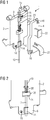
- the FIG. 1 shows the holding device 1 with the first holding element 2 and the second holding element 4.
- the first holding element 2 shows a substantially rectangular, flat basic shape with an extension 6, which extends in the direction of a receiving position not shown in detail for blood collection tube. From the extension 6 to the opposite edge 8 of the first holding element 2 extends centrally a groove 10 in which a cylindrical hollow needle 12 is guided.
- the terms used in the following axial and radial always refer to the cylindrical shape of the hollow needle.
- the hollow needle 12 is mounted in two bearing bushes 14, which are arranged in the region of the edge 8 and on the extension 6.
- the hollow needle 12 extends beyond the groove 10 also.
- On the side of the extension 6, the hollow needle 12 extends to its tip, not shown, for piercing the closure of a blood collection tube.
- the second retaining element 4 has holes into which screws 16 can be introduced. By means of corresponding threaded holes 18 in the first holding element. 2 the second holding element 4 can be fixed to the first holding element.
- the second holding element 4 is designed such that it extends over the entire groove 10 of the first holding element 2 and has a congruent groove 20 to the groove 10 on the first holding element 2. In the connected state, the hollow needle 12 is thus fixed between the holding elements 2, 4 in the bearing bushes 14 and is movable only in the axial direction.
- the second holding element has handles 22 for easy removal of the holding device 1.
- the removal process is in the FIGS. 4 to 6 explained.
- the rest in FIG. 1 already shown features are also explained in more detail below.
- FIG. 2 shows enlarged the lower part of the first holding element 2.
- the first holding element 2 has a cuboid cavity 24 which interrupts the groove 10.
- a parallelepiped stop 26 is fixed, which completely fills the cavity 24 in the radial plane, but in the axial direction has a lower height than the cavity 24. The axial movement of the hollow needle 12 in the groove 10 is thus limited to the difference in height between the stop 26 and cavity 24.
- FIG. 1 shows here the rest position, ie without force, while FIG. 2 the position in a crash state, that is, with force on the needle point shows.
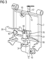
- FIG. 3 shows opposite FIG. 2 the rear side of the upper part of the first holding element 2.
- a bolt 30 is fixed on the back, which is mounted in a bore 32 of a movable parallelepiped 34 in the axial direction.
- the cuboid 34 has a front side facing shoulder 36.
- a gap is provided, in which engages an end of a lever 38 which is mounted with an axis 40 on the first support member 2, and whose free end protrudes beyond the edge of the first support member 2 addition.
- the axial position of the hollow needle 12 can thus be influenced from outside the holding device 1. This occurs, for example, when piercing a closure of a blood collection tube.
- the lever 38 is actuated, so that the hollow needle 12 in the in FIG. 2 shown position is brought. As a result, the hollow needle 12 is stabilized during piercing.
- an unspecified described element of a position measuring device is arranged on the cuboid 34 .
- This can be, for example, a reflector for a light barrier, a microswitch or the like. In this way, the relative position of the hollow needle 12 to the holding element 2 can be determined and a crash can be reliably detected.
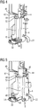
- FIG. 4 shows the connected by means of screws 16 holding elements 2, 4 FIG. 1 , which are arranged as a holding device 1 on a base plate 42.
- the base plate 42 is connected to an electric or hydraulic motor, not shown, and can therefore be automatically moved by the control unit of the automatic analyzer as part of the analysis.
- the release of the retaining element 2 for replacement of the hollow needle 12 is in the FIG. 5 and 6 shown.
- the self-aligning rollers 49 displaced by means of an axle 54 are displaced.
- the holding element 2 is released in the connecting element 50 and turned out in the hinge 52. Due to the omission of the positive connection in the connecting element 50, the hollow cylinder 44 can be released from the bearings 46. With sufficient tension, the holding device 1 can thus be removed, see FIG. 5 ,
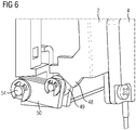
- FIG. 6 shows enlarged mounted in the axis 54, self-recovering roller 49th
Description
Die Erfindung betrifft eine Haltevorrichtung für eine Hohlnadel zum Durchstoßen des Deckels eines Probenröhrchens in einem automatischen Analysegerät.The invention relates to a holding device for a hollow needle for piercing the lid of a sample tube in an automatic analyzer.
Zahlreiche Nachweis- und Analyseverfahren zur Bestimmung physiologischer Parameter in Körperflüssigkeitsproben oder anderer biologischer Proben werden heute automatisiert in großer Anzahl in automatischen Analysegeräten, auch sogenannten in vitro-Diagnostiksystemen, durchgeführt.Numerous detection and analysis methods for the determination of physiological parameters in body fluid samples or other biological samples are nowadays automatically performed in large numbers in automatic analyzers, also known as in vitro diagnostic systems.
Um eine Vielzahl von Untersuchungen automatisiert durchführen zu können, sind diverse Vorrichtungen zum räumlichen Transfer von Probenbehältern, Reaktionsbehältern und Reagenzbehältern erforderlich, wie z.B. Transferarme mit Greiffunktion, Transportbänder oder drehbare Transporträder. Weiterhin sind Pipettiervorrichtungen zum Transfer von Flüssigkeiten vorgesehen. Die Analysegeräte umfassen ferner eine Steuereinheit, die mittels entsprechender Software dazu in der Lage ist, die Arbeitsschritte für die gewünschten Analysen weitgehend selbstständig zu planen und abzuarbeiten.In order to automate a variety of investigations, various devices for the spatial transfer of sample containers, reaction containers and reagent containers are required, such as e.g. Transfer arms with gripping function, conveyor belts or rotatable transport wheels. Furthermore, pipetting devices are provided for the transfer of liquids. The analysis devices further include a control unit, which is by means of appropriate software to be able to largely independently plan the work steps for the desired analyzes and work off.
Viele der in derartigen automatisiert arbeitenden Analysegeräten verwendeten Messsysteme beruhen auf optischen Methoden. Diese Verfahren ermöglichen den qualitativen und quantitativen Nachweis von Analyten in flüssigen Proben. Die Bestimmung klinisch relevanter Parameter, wie zum Beispiel der Konzentration oder der Aktivität eines Analyten, erfolgt vielfach, indem ein Teil einer Körperflüssigkeit eines Patienten, z.B. Blut, Plasma, Serum oder Urin, mit einem oder mehreren Testreagenzien in einem Reaktionsgefäß vermischt wird, wodurch eine biochemische Reaktion in Gang gesetzt wird, die eine messbare Veränderung einer optischen oder anderen physikalischen Eigenschaft des Testansatzes bewirkt.Many of the measurement systems used in such automated analyzers rely on optical methods. These methods enable the qualitative and quantitative detection of analytes in liquid samples. Determination of clinically relevant parameters, such as the concentration or activity of an analyte, is often accomplished by mixing a portion of a body fluid of a patient, eg, blood, plasma, serum, or urine, with one or more test reagents in a reaction vessel to produce a biochemical reaction set in motion which causes a measurable change in an optical or other physical property of the assay.
Die Proben werden dem Gerät üblicherweise in Probengefäßen, wie z.B. Blutentnahmeröhrchen zugeführt. Blutentnahmeröhrchen sind üblicherweise aus transparentem Kunststoff gefertigt und sind an der Spitze mit einem speziellen Anschluss für Kanülen ausgestattet. Blutentnahmeröhrchen sind (außer beim so genannten Sarstedt-Prinzip) häufig als Unterdrucksysteme ausgestaltet, d.h.innerhalb des Probengefäßes herrscht von vornherein ein Unterdruck. Wird es auf den mit der Punktionskanüle verbundenen Adapter gesteckt, wird durch diesen Unterdruck das Blut angesaugt. Ein Vorteil dieses Systems ist, dass die angesaugte Blutmenge vergleichsweise konstant ist und somit auch die Menge eines vorab in das Blutentnahmeröhrchen eingebrachten Gerinnungshemmers (z.B. Citrat, EDTA, Heparin) genau bemessen werden kann. Die Blutentnahmeröhrchen sind üblicherweise zur Erhaltung des Drucks mit einem elastischen Verschluss abgedichtet.The samples are usually placed in the sample vessel, e.g. Supplied to blood collection tube. Blood collection tubes are usually made of transparent plastic and are equipped at the tip with a special connection for cannulas. Blood collection tubes are (except in the so-called Sarstedt principle) often configured as a vacuum systems, that is, within the sample vessel there is a negative pressure from the outset. If it is placed on the adapter connected to the puncture cannula, the blood is sucked in by this negative pressure. An advantage of this system is that the amount of blood drawn in is comparatively constant, and thus the amount of anticoagulant introduced in advance into the blood collection tube (e.g., citrate, EDTA, heparin) can be accurately measured. The blood collection tubes are usually sealed to maintain pressure with an elastic closure.
Um eine Untersuchung automatisiert durchführen zu können, ist es erforderlich, ein Aliquot der Blutprobe aus dem Blutentnahmeröhrchen zu entnehmen und in das für die jeweilige Untersuchung bestimmte Reaktionsgefäß zu transferieren. Hierzu sind Pipettiervorrichtungen in dem Analysegerät vorgesehen. Übliche Pipettiervorrichtungen umfassen eine mittels einer Haltevorrichtung befestigte Hohlnadel, die durch Druck oder Unterdruck betrieben definierte Probenmengen entnehmen und abgeben kann. Derartige Nadeln haben eine im Wesentlichen zylinderförmige Grundform mit einem zentralen Hohlkanal, wobei die Hohlnadel axiale Abschnitte mit variierenden Innen- und Außenradien aufweisen kann. Als Grundfläche des Zylinders wird dabei üblicherweise ein Kreis gewählt, andere Grundformen sind jedoch möglich. Die Spitze der Nadel ist üblicherweise konisch ausgeformt oder, wenn sie dazu vorgesehen ist, den Deckel von verschlossenen Blutentnahmeröhrchen oder anderen Flüssigkeitsbehältnissen zu durchstoßen, schräg angespitzt.In order to be able to carry out an investigation automatically, it is necessary to take an aliquot of the blood sample from the blood collection tube and to transfer it into the reaction vessel intended for the particular examination. For this purpose, pipetting devices are provided in the analysis device. Conventional pipetting devices comprise a hollow needle fastened by means of a holding device, which can remove and dispense defined amounts of sample operated by pressure or underpressure. Such needles have a substantially cylindrical basic shape with a central hollow channel, wherein the hollow needle may have axial sections with varying inner and outer radii. As a base of the cylinder while a circle is usually chosen, but other basic shapes are possible. The tip of the needle is usually conical or, if provided, the lid of Pierced blood collection tube or other liquid containers to pierce, obliquely pointed.
Zur Entnahme von Probenflüssigkeit aus einem Probenbehälter wird die Hohlnadel entlang der Mittelachse des Probenröhrchens eingeführt, durchsticht den elastischen Verschlussstopfen und wird so in die Probenflüssigkeit eingetaucht. Das Eintauchen wird üblicherweise mittels eines entsprechenden Sensors registriert und die vorgegebene Menge druckluftgesteuert eingesaugt.To remove sample liquid from a sample container, the hollow needle is introduced along the central axis of the sample tube, pierces the elastic sealing plug and is so immersed in the sample liquid. The immersion is usually registered by means of a corresponding sensor and sucked the predetermined amount compressed air controlled.
Da die Hohlnadel vergleichsweise massiv ausgeführt ist und die elastischen Stopfen von Probenröhrchen aus festem Gummi mit einer Dicke von bis zu 1 cm gefertigt sind, ist eine relativ hohe Kraft zum Durchstoßen eines Verschlussstopfens notwendig. Hier kann es durch eine Verschiebung der Nadel zu Fehlern bei der Probenaufnahme und zu entsprechenden Folgefehlern in der Probenauswertung kommen. Weiterhin kommt es im Verlauf vieler Durchstoßvorgänge zu einer Abnutzung der Nadel, so dass die Hohlnadel regelmäßig ausgetauscht werden muss.Since the hollow needle is made comparatively massive and the elastic plugs of sample tubes made of solid rubber with a thickness of up to 1 cm, a relatively high force for piercing a sealing plug is necessary. In this case, a displacement of the needle can lead to errors during sample taking and to corresponding follow-on errors in the sample evaluation. Furthermore, in the course of many piercing operations, the needle is worn out so that the hollow needle has to be replaced regularly.
Es ist daher Aufgabe der Erfindung, eine Haltevorrichtung für eine Hohlnadel zum Durchstoßen des Deckels eines Probenröhrchens bereit zu stellen, die einen besonders stabilen Halt der Hohlnadel bietet und gleichzeitig einen einfachen Austausch der Hohlnadel im Verschleißfall ermöglicht.It is therefore an object of the invention to provide a holding device for a hollow needle for piercing the lid of a sample tube, which provides a particularly stable hold of the hollow needle and at the same time allows easy replacement of the hollow needle in case of wear.
Diese Aufgabe wird erfindungsgemäß gelöst, indem die Haltevorrichtung ein erstes, an einer automatisiert bewegbaren Basisplatte eines automatischen Analysegeräts lösbar befestigbares Halteelement und ein zweites, mit dem ersten Halteelement lösbar verbundenes Halteelement umfasst, wobei zwischen den Halteelementen mindestens eine Lagerbuchse fixiert ist, in der die Hohlnadel gelagert ist, wobei das erste Halteelement einen Hohlraum umfasst, der einen an der Hohlnadel befestigten Anschlag derart umschließt, dass die Bewegung der Hohlnadel in der mindestens einen Lagerbuchse begrenzt wird.This object is achieved by the holding device comprises a first, releasably attachable to an automatically movable base plate of an automatic analyzer holding element and a second, releasably connected to the first holding element holding element, wherein between the holding elements at least one bearing bush is fixed, in which the hollow needle is mounted, wherein the first holding element comprises a cavity having a stop attached to the hollow needle such encloses that the movement of the hollow needle is limited in the at least one bearing bush.
Dies bewirkt eine gute Lagerung und damit einen stabilen Halt und eine präzise Positionierung der Hohlnadel in radialer Richtung, was für die Durchstoßgenauigkeit der Hohlnadel erforderlich ist. Ein weiterer Vorteil besteht in der leichten Austauschbarkeit der Hohlnadel und darin, dass nach dem Austausch der Nadel nicht neu justiert werden muss. Eine lösbare Verbindung der Haltevorrichtung an einer automatisiert bewegbaren Basisplatte des automatischen Analysegeräts sorgt hier für eine stabile Positionierung, so dass die neue Hohlnadel ebenso genau positioniert ist wie die bisherige Hohlnadel. Durch Lösen der Verbindung kann eine verschlissene Hohlnadel mitsamt Haltevorrichtung entnommen und eine neue Hohlnadel mit Haltevorrichtung eingesetzt werden. Eine Verbindung der neuen Haltevorrichtung fixiert die neue Hohlnadel in der mindestens einen Lagerbuchse.This causes a good storage and thus a stable hold and precise positioning of the hollow needle in the radial direction, which is required for the puncture accuracy of the hollow needle. Another advantage is the easy interchangeability of the hollow needle and that does not need to be readjusted after replacement of the needle. A detachable connection of the holding device to an automatically movable base plate of the automatic analyzer ensures a stable positioning, so that the new hollow needle is just as accurately positioned as the previous hollow needle. By loosening the connection, a worn hollow needle can be removed together with holding device and a new hollow needle with holding device can be used. A compound of the new holding device fixes the new hollow needle in the at least one bearing bush.
Die Lagerbuchse hat den weiteren Vorteil, dass eine axiale Bewegung der Hohlnadel möglich ist. Dadurch wird ermöglicht, einen unvorhergesehenen Kontakt der Nadel, einen sogenannten Crash, z.B. mit der Innenwand des Blutentnahmeröhrchens zu erkennen. Bei einem Crash weicht die Nadel im Hohlraum in axialer Richtung aus, was von entsprechenden Detektoren erkannt werden kann. Diese Ausweichbewegung sollte jedoch begrenzt werden, da andernfalls die Positionierung und Stabilität der Hohlnadel gefährdet wird. Andererseits muss bei einem erwünschten Kontakt, nämlich beim Durchstoßen des Verschlusses des Blutentnahmeröhrchens eine ausreichende Kraftausübung in axialer Richtung ermöglicht werden. Hierzu weist die Hohlnadel einen Anschlag auf, der sich vorteilhafterweise in radialer Richtung erstreckt. Das erste Halteelement weist einen Hohlraum auf, der den Anschlag umschließt, dabei jedoch nicht fixiert, sondern noch eine axiale Bewegung erlaubt, die lediglich hinsichtlich ihrer Weite begrenzt wird.The bearing bush has the further advantage that an axial movement of the hollow needle is possible. This makes it possible to detect an unforeseen contact of the needle, a so-called crash, for example, with the inner wall of the blood collection tube. In a crash, the needle deviates in the cavity in the axial direction, which can be detected by corresponding detectors. However, this evasive movement should be limited because otherwise the positioning and stability of the hollow needle is compromised. On the other hand, in the case of a desired contact, namely when piercing the closure of the blood collection tube, it must be possible to exert sufficient force in the axial direction. For this purpose, the hollow needle has a stop which advantageously extends in the radial direction. The first holding element has a cavity which surrounds the stop, but not fixed, but still allows an axial movement, which is limited only in terms of their width.
Vorteilhafterweise ist der Hohlnadel ein Rückstellelement zugeordnet. Hierdurch wird gewährleistet, dass trotz der Beweglichkeit der Hohlnadel in axialer Richtung eine vorgegebene Standardposition existiert, in die die Hohlnadel ohne Krafteinwirkung von außen selbständig zurückkehrt, z.B. nach einer Ausweichbewegung der Hohlnadel in Folge eines Crashs. Die vorgegebene Standardposition vereinfacht es auch, einen derartigen Crash mittels eines entsprechenden Crashsensors zu detektieren.Advantageously, the hollow needle is associated with a return element. This ensures that despite the mobility of the hollow needle in the axial direction, a predetermined standard position exists, in which the hollow needle automatically returns from the outside without external force, e.g. after an evasive movement of the hollow needle as a result of a crash. The predetermined standard position also makes it easier to detect such a crash by means of a corresponding crash sensor.
Das Rückstellelement ist vorteilhafterweise eine zwischen Anschlag und erstem Halteelement befestigte Feder. Im kraftfreien Zustand, d.h. ohne Kontakt der Nadel mit einem Widerstand ist dadurch in technisch besonders einfacher Weise eine Standardposition definiert.The return element is advantageously a fixed between the stop and the first retaining element spring. In the power-free state, i. without contact of the needle with a resistor, a standard position is thereby defined in a technically particularly simple manner.
In weiterer vorteilhafter Ausgestaltung umfasst der Anschlag einen Bolzen, der mit einem gelagerten Hebel verbunden ist. Der Hebel ist dabei vorteilhafterweise so angeordnet und ausgebildet, dass er von außerhalb der Haltevorrichtung betätigt werden kann. Dadurch ist es möglich, durch eine entsprechende Betätigungsvorrichtung für den Hebel am automatischen Analysegerät die Position der Nadel in axialer Richtung gezielt einzustellen. Insbesondere wird beim Durchstoßen des Verschlusses eines Blutentnahmeröhrchens der Hebel automatisiert betätigt und die Nadel mit ihrem Anschlag in die maximale Ausweichposition gebracht, so dass sie im Hohlraum anliegt, beim Durchstoßen keine weitere Bewegung mehr vollführt und dadurch stabilisiert wird.In a further advantageous embodiment, the stop comprises a bolt which is connected to a mounted lever. The lever is advantageously arranged and designed so that it can be operated from outside the holding device. This makes it possible to selectively adjust the position of the needle in the axial direction by a corresponding actuator for the lever on the automatic analyzer. In particular, when pushing through the closure of a blood collection tube, the lever is automatically actuated and the needle is brought with its stop in the maximum evasive position, so that it rests in the cavity, the piercing no further movement more performs and is thereby stabilized.
Vorteilhafterweise ist mit dem Bolzen ein Element einer Positionsmesseinrichtung verbunden. Das Element kann je nach Art der Positionsmesseinrichtung variieren, z.B. kann ein Mikroschalter vorgesehen sein oder ein Reflektionselement für eine Lichtschranke. In allen Fällen kann dabei die Relativbewegung des Bolzens zur Haltevorrichtung ermittelt werden, so dass die Detektion eines Crashs in besonders einfacher Weise ermöglicht wird.Advantageously, an element of a position-measuring device is connected to the bolt. The element may vary depending on the type of position measuring device, for example, may be provided a microswitch or a reflection element for a light barrier. In all cases, the relative movement of the bolt to the holding device can be determined be so that the detection of a crash in a particularly simple manner is possible.
Das erste Halteelement einer beschriebene Haltevorrichtung ist vorteilhafterweise mit einer automatisiert bewegbaren Basisplatte des automatischen Analysegeräts verbunden.The first holding element of a holding device described is advantageously connected to an automatically movable base plate of the automatic analyzer.
Vorteilhafterweise umfasst die Verbindung des ersten Halteelements mit der Basisplatte ein Gelenk, welches in einer ersten Position mittels Formschluss ein Lösen des ersten Halteelements verhindert und in einer zweiten Position ein Lösen des ersten Halteelements erlaubt. Eine derartige Ausführung vereinigt in besonders einfacher Weise das Erfordernis der stabilen Positionierung und leichten Entnehmbarkeit der Hohlnadel. In der ersten Position ist durch den Formschluss ein Lösen ausgeschlossen, so dass eine stabile Positionierung gewährleistet ist. Wird das Gelenk manuell in die zweite Position gebracht, kann die Haltevorrichtung mit der Nadel einfach entnommen werden.Advantageously, the connection of the first holding element with the base plate comprises a joint, which in a first position by means of positive locking prevents release of the first holding element and in a second position allows release of the first holding element. Such a design combines in a particularly simple manner the requirement of stable positioning and easy removability of the hollow needle. In the first position a release is excluded by the positive connection, so that a stable positioning is ensured. If the joint is manually moved to the second position, the holding device with the needle can be easily removed.
In weiterer vorteilhafter Ausgestaltung umfasst die Verbindung ein Verbindungselement, welches das erste Halteelement formschlüssig mit der Basisplatte verbindet und welches unter Krafteinwirkung wiederverschließbar öffnet. Das Verbindungselement dient somit dazu, die Verbindung des ersten Halteelements mit der Basisplatte in der ersten Position des Gelenks zu fixieren. Erst durch entsprechende Krafteinwirkung auf das Verbindungselement kann dann das Gelenk in die zweite Position bewegt und die Haltevorrichtung von der Basisplatte entnommen werden. Eine neue Haltevorrichtung mit neuer Hohlnadel wird wieder eingesetzt und das Gelenk in die erste Position gedreht. Auf Grund der Wiederverschließbarkeit des Verbindungselements wird die Haltevorrichtung dann auf einfache Weise wieder fixiert.In a further advantageous embodiment, the connection comprises a connecting element which connects the first holding element in a form-fitting manner with the base plate and which recloses under the action of force. The connecting element thus serves to fix the connection of the first holding element with the base plate in the first position of the joint. Only then by appropriate force on the connecting element, the joint can then be moved to the second position and the holding device can be removed from the base plate. A new holding device with a new hollow needle is inserted again and the joint is rotated in the first position. Due to the reclosability of the connecting element, the holding device is then fixed again in a simple manner.
Als Verbindungselement sind hier verschiedene wiederverschließbare Konstruktionen denkbar. Ein besonders stabiler Halt mit einer genauen Positionierung wird vorteilhafterweise dadurch erreicht, dass das Verbindungselement aus einer Ruheposition selbstrückstellend verschiebbare Rollen aufweist. Diese sollten so angeordnet sein, dass sie sich bei einer Krafteinwirkung durch Ziehen an der Haltevorrichtung verschieben und somit eine Bewegung des Gelenks in die zweite Position und Entnahme der Haltevorrichtung erlauben.As a connecting element different resealable constructions are conceivable here. A special Stable hold with a precise positioning is advantageously achieved in that the connecting element from a rest position self-resetting sliding rollers. These should be arranged so that they move by a pulling force on the holding device and thus allow movement of the joint in the second position and removal of the holding device.
Ein weiterer Gegenstand der vorliegenden Erfindung ist ein automatisches Analysegerät mit einer Pipettiervorrichtung umfassend eine Hohlnadel, wobei die Pipettiervorrichtung eine beschriebene Haltevorrichtung für die Hohlnadel umfasst.Another object of the present invention is an automatic analyzer with a pipetting device comprising a hollow needle, wherein the pipetting device comprises a described holding device for the hollow needle.
Die mit der Erfindung erzielten Vorteile bestehen insbesondere darin, dass durch die beschriebene lösbar verbundene Lagerung der Hohlnadel in einer Haltevorrichtung einerseits ein stabiler Halt und eine hohe Positionierungsgenauigkeit erreicht werden und andererseits eine leichte Austauschbarkeit einer verschlissenen Hohlnadel ermöglicht wird. Die Konstruktion erleichtert somit die automatisierte Entnahme von Probenflüssigkeiten aus verschlossenen Probenbehältern in einem automatischen Analysegerät.The advantages achieved by the invention are in particular that a stable hold and high positioning accuracy can be achieved by the described releasably connected storage of the hollow needle in a holding device on the one hand and on the other hand easy replacement of a worn hollow needle is possible. The design thus facilitates the automated removal of sample liquids from sealed sample containers in an automatic analyzer.
Die Erfindung wird anhand einer Zeichnung näher erläutert. Darin zeigen:
- FIG 1
- erstes und zweites Halteelement einer Haltevorrichtung mit eingesetzter Hohlnadel in voneinander gelöster Position,
- FIG 2
- das erste Halteelement vorderseitig mit Darstellung des Hohlraums,
- FIG 3
- das erste Halteelement rückseitig mit dem Hebel zur Betätigung der Hohlnadelposition,
- FIG 4
- die Haltevorrichtung mit Basisplatte in verbundenem Zustand,
- FIG 5
- die Haltevorrichtung mit gelöstem Gelenk, und
- FIG 6
- ausschnittsweise das Verbindungselement der Haltevorrichtung mit gelöstem Gelenk.
- FIG. 1
- first and second retaining element of a holding device with inserted hollow needle in a detached position,
- FIG. 2
- the first holding element on the front side showing the cavity,
- FIG. 3
- the first holding element on the back with the lever for actuating the hollow needle position,
- FIG. 4
- the holding device with the base plate in the connected state,
- FIG. 5
- the holding device with dissolved joint, and
- FIG. 6
- fragmentary, the connecting element of the holding device with dissolved joint.
Gleiche Teile sind in allen Figuren mit denselben Bezugszeichen versehen.Identical parts are provided with the same reference numerals in all figures.
Die
Die Hohlnadel 12 ist in zwei Lagerbuchsen 14 gelagert, die im Bereich der Kante 8 und auf dem Fortsatz 6 angeordnet sind. Die Hohlnadel 12 erstreckt sich über die Nut 10 hinaus. Auf der Seite der Kante 8 weist sie einen Anschluss 15 für einen Schlauch zur Beaufschlagung des Hohlraums der Hohlnadel 12 mittels Druck oder Unterdruck auf. Auf der Seite des Fortsatzes 6 erstreckt sich die Hohlnadel 12 bis zu ihrer nicht gezeigten Spitze zum Durchstoßen des Verschlusses eines Blutentnahmeröhrchens.The
Das zweite Halteelement 4 weist Bohrungen auf, in die Schrauben 16 eingebracht werden können. Mittels entsprechender Gewindebohrungen 18 im ersten Halteelement 2 kann das zweite Halteelement 4 am ersten Halteelement fixiert werden. Das zweite Halteelement 4 ist dabei so ausgestaltet, dass es sich über die gesamte Nut 10 des ersten Halteelements 2 erstreckt und weist eine deckungsgleiche Nut 20 zur Nut 10 am ersten Halteelement 2 auf. Im verbundenen Zustand wird die Hohlnadel 12 somit zwischen den Halteelementen 2, 4 in den Lagerbuchsen 14 fixiert und ist nur noch in axialer Richtung bewegbar.The
Das zweite Halteelement weist Griffe 22 zur leichten Entnahme der Haltevorrichtung 1 auf. Der Entnahmevorgang wird in den
Eine Feder 28 verbindet den Anschlag 26 und das erste Halteelement 2, so dass die Position der Hohlnadel 12 in axialer Richtung selbstrückstellend ist.
Zwischen dem Absatz 36 und dem Bolzen 30 ist ein Zwischenraum vorgesehen, in welchen ein Ende eines Hebels 38 eingreift, der mit einer Achse 40 am ersten Halteelement 2 gelagert ist, und dessen freies Ende über den Rand des ersten Halteelements 2 hinaus ragt. Am freien Ende des Hebels 38 kann somit von außerhalb der Haltevorrichtung 1 die axiale Lage der Hohlnadel 12 beeinflusst werden. Dies erfolgt beispielsweise beim Durchstoßen eines Verschlusses eines Blutentnahmeröhrchens. Durch eine nicht näher gezeigte Vorrichtung des automatischen Analysegeräts wird der Hebel 38 betätigt, so dass die Hohlnadel 12 in die in
Am Quader 34 ist ein nicht näher beschriebenes Element einer Positionsmessvorrichtung angeordnet. Dies kann beispielsweise ein Reflektor für eine Lichtschranke, ein Mikroschalter oder Ähnliches sein. Hierdurch kann die Relativposition der Hohlnadel 12 zum Halteelement 2 ermittelt werden und ein Crash zuverlässig detektiert werden.On the cuboid 34 an unspecified described element of a position measuring device is arranged. This can be, for example, a reflector for a light barrier, a microswitch or the like. In this way, the relative position of the
Die Befestigung der Haltevorrichtung 1 mittels des ersten Halteelements 2 an der Basisplatte 42 erfolgt über Hohlzylinder 44, die beiderseits am Rand der Kante 8 des ersten Halteelements 2 fest angeordnet sind. Diese greifen in trapezförmig ausgeschnittene, den Hohlzylindern 44 angeformte Lager 46 an der Basisplatte 42 ein. Durch die Trapezform der Lager 46 in Verbindung mit der Hohlzylinderform wird eine besonders ortsgenaue Lagerung ermöglicht. An seinem unteren Teil weist das erste Halteelement 2 der Basisplatte 42 zugewandte Fortsätze 48 auf, die zusammen mit selbstrückstellenden, verschiebbaren Rollen 49 ein Verbindungselement 50 bilden, welches das erste Halteelement 2 formschlüssig mit der Basisplatte 42 verbindet und unter Krafteinwirkung wiederverschließbar öffnet. Auch hier sorgt die runde Form der Rollen 49 in Verbindung mit einer keilförmig eingeschnittenen Form des Fortsatzes 48 für eine genaue automatische Justierung. In der in
Das Lösen des Halteelements 2 zum Austausch der Hohlnadel 12 ist in den
Dem Benutzer wird eine Austauschnadel direkt in einer neuen Haltevorrichtung 1 geliefert. Der Einbau erfolgt in umgekehrter Reihenfolge. Somit ist ein einfacher Austausch einer verschlissenen Hohlnadel 12 möglich, und es bleibt eine genaue Positionierung gewährleistet.The user is supplied with a replacement needle directly in a new fixture 1. Installation is the reverse order. Thus, a simple replacement of a worn
- 11
- Haltevorrichtungholder
- 22
- erstes Halteelementfirst holding element
- 44
- zweites Halteelementsecond holding element
- 66
- Fortsatzextension
- 88th
- Kanteedge
- 1010
- Nutgroove
- 1212
- Hohlnadelcannula
- 1414
- Lagerbuchsebearing bush
- 1515
- Anschlussconnection
- 1616
- Schraubescrew
- 1818
- Gewindebohrungthreaded hole
- 2020
- Nutgroove
- 2222
- GriffHandle
- 2424
- Hohlraumcavity
- 2626
- Anschlagattack
- 2828
- Federfeather
- 3030
- Bolzenbolt
- 3232
- Bohrungdrilling
- 3434
- Quadercuboid
- 3636
- Absatzparagraph
- 3838
- Hebellever
- 4040
- Achseaxis
- 4242
- Basisplattebaseplate
- 4444
- Hohlzylinderhollow cylinder
- 4646
- Lagercamp
- 4848
- Fortsatzextension
- 4949
- Rollenroll
- 5050
- Verbindungselementconnecting element
- 5252
- Gelenkjoint
- 5454
- Achseaxis
Claims (10)
- Retaining device (1) for a hollow needle (12) for puncturing the lid of a blood sampling tube, comprising a first retaining element (2), which can be secured releasably on a base plate (42) of an automatic analysis apparatus, which base plate (42) is movable in an automated manner, and a second retaining element (4), which is connected to the first retaining element (2), characterized in that at least one bearing bushing (14) is provided, which is fixed between the retaining elements (2, 4) and in which the hollow needle (12) is mounted, wherein the first retaining element (2) comprises a hollow space (24) in which an abutment (26), secured on the hollow needle (12), is enclosed in such a way that the movement of the hollow needle (12) in the at least one bearing bushing (14) is limited.
- Retaining device (1) according to Claim 1, in which a restoring element (28) is assigned to the hollow needle (12).
- Retaining device (1) according to Claim 2, in which the restoring element (28) is a spring (28) secured between abutment (26) and first retaining element (2).
- Retaining device (1) according to one of Claims 2 and 3, in which the abutment (26) comprises a bolt (30), which is connected to a lever (38) mounted in a bearing.
- Retaining device (1) according to Claim 4, in which an element of a position-measuring device is connected to the bolt (30) .
- Retaining device (1) according to one of the preceding claims, in which the first retaining element (2) is connected releasably to a base plate (42) of the automatic analysis apparatus, which base plate (42) is movable in an automated manner.
- Retaining device (1) according to one of the preceding claims, in which the connection of the first retaining element (2) to the base plate (42) comprises a joint (52) which, in a first position, prevents release of the first retaining element (2), by means of a form fit, and, in a second position, permits release of the first retaining element (2).
- Retaining device (1) according to Claim 7, in which the connection comprises a connection element (50), which connects the first retaining element (2) to the base plate (42) with a form fit and which, under the effect of a force, opens in a manner allowing it to reclose.
- Retaining device (1) according to Claim 8, in which the connection element (50) has rollers (49), which are movable from a rest position in a self-restoring manner.
- Automatic analysis apparatus with a pipetting device comprising a hollow needle, characterized in that the pipetting device comprises a retaining device (1) for the hollow needle according to one of the preceding claims.
Priority Applications (5)
| Application Number | Priority Date | Filing Date | Title |
|---|---|---|---|
| ES13158896T ES2764774T3 (en) | 2013-03-13 | 2013-03-13 | Retention device for a pipetting needle |
| EP13158896.4A EP2778688B1 (en) | 2013-03-13 | 2013-03-13 | Holding device for a pipetting needle |
| JP2014045160A JP6353244B2 (en) | 2013-03-13 | 2014-03-07 | Pipette needle holding device |
| US14/206,603 US9091672B2 (en) | 2013-03-13 | 2014-03-12 | Retaining device for a pipetting needle |
| CN201410090703.8A CN104049092B (en) | 2013-03-13 | 2014-03-12 | Liquid-transfering needle holding meanss |
Applications Claiming Priority (1)
| Application Number | Priority Date | Filing Date | Title |
|---|---|---|---|
| EP13158896.4A EP2778688B1 (en) | 2013-03-13 | 2013-03-13 | Holding device for a pipetting needle |
Publications (2)
| Publication Number | Publication Date |
|---|---|
| EP2778688A1 EP2778688A1 (en) | 2014-09-17 |
| EP2778688B1 true EP2778688B1 (en) | 2019-10-30 |
Family
ID=47877889
Family Applications (1)
| Application Number | Title | Priority Date | Filing Date |
|---|---|---|---|
| EP13158896.4A Active EP2778688B1 (en) | 2013-03-13 | 2013-03-13 | Holding device for a pipetting needle |
Country Status (5)
| Country | Link |
|---|---|
| US (1) | US9091672B2 (en) |
| EP (1) | EP2778688B1 (en) |
| JP (1) | JP6353244B2 (en) |
| CN (1) | CN104049092B (en) |
| ES (1) | ES2764774T3 (en) |
Families Citing this family (7)
| Publication number | Priority date | Publication date | Assignee | Title |
|---|---|---|---|---|
| WO2016156390A1 (en) * | 2015-03-30 | 2016-10-06 | Bd Kiestra B.V | Surface detection and picktool manipulator |
| EP3088904A1 (en) * | 2015-04-27 | 2016-11-02 | Siemens Healthcare Diagnostics Products GmbH | Method for checking the functionality of a washing station for pipette needles |
| EP3096148B1 (en) * | 2015-05-20 | 2024-01-03 | Siemens Healthcare Diagnostics Products GmbH | Pipetting device |
| EP3454987B1 (en) * | 2016-05-12 | 2021-06-30 | Siemens Healthcare Diagnostics Inc. | Clinical analyzer probe crash detection mechanism and process |
| CN106770847A (en) * | 2016-12-31 | 2017-05-31 | 浙江福立分析仪器股份有限公司 | Automatic sampler and sample injection method |
| CN115667908A (en) | 2020-03-17 | 2023-01-31 | 沃特世科技公司 | Sample manager, system and method |
| EP4121754A1 (en) | 2020-03-17 | 2023-01-25 | Waters Technologies Corporation | Needle drive, system and method |
Family Cites Families (14)
| Publication number | Priority date | Publication date | Assignee | Title |
|---|---|---|---|---|
| US4140488A (en) * | 1977-09-06 | 1979-02-20 | Hycel, Inc. | Sample liquid transfer means in an automatic chemical testing apparatus |
| US5807523A (en) * | 1996-07-03 | 1998-09-15 | Beckman Instruments, Inc. | Automatic chemistry analyzer |
| JP3687019B2 (en) * | 1996-10-16 | 2005-08-24 | アークレイ株式会社 | Sampling device |
| DE19835833A1 (en) * | 1998-08-07 | 2000-02-17 | Max Planck Gesellschaft | Dosing head for parallel processing of a large number of fluid samples |
| DE19847759A1 (en) * | 1998-10-16 | 2000-04-20 | Dade Behring Marburg Gmbh | Interchangeable vibrating pipette needle |
| US20040054286A1 (en) * | 2001-11-05 | 2004-03-18 | Audain Vaughn A | Ultrasonic transducing probe with liquid flow-through capability and related automated workstation and methods of using same |
| DE10308362A1 (en) * | 2003-02-27 | 2004-09-09 | Roche Diagnostics Gmbh | System for automatic opening of test tubes |
| FR2857750B1 (en) * | 2003-07-18 | 2008-04-18 | C2 Diagnostics | DEVICE AND METHOD FOR SAMPLING AN ANALYSIS AUTOMATE |
| JP4476906B2 (en) * | 2005-09-02 | 2010-06-09 | 富士フイルム株式会社 | Dispensing device |
| FR2920675B1 (en) * | 2007-09-10 | 2010-12-03 | Gilson Sas | MULTICHANNEL PIPETTING SYSTEM COMPRISING AN IMPROVED GUIDE PISTON HOLDER |
| JP2010078335A (en) * | 2008-09-24 | 2010-04-08 | Olympus Corp | Autoanalyzer and transfer unit |
| US7919061B2 (en) * | 2008-10-30 | 2011-04-05 | Ome Technology Co., Ltd. | Pipette device system and micropipette thereof |
| WO2010082080A1 (en) * | 2009-01-16 | 2010-07-22 | Gilson S.A.S. | Multi-channel pipette guidance system |
| US9696332B2 (en) * | 2010-07-23 | 2017-07-04 | Matrix Technologies Llc | Automated liquid handling device |
-
2013
- 2013-03-13 ES ES13158896T patent/ES2764774T3/en active Active
- 2013-03-13 EP EP13158896.4A patent/EP2778688B1/en active Active
-
2014
- 2014-03-07 JP JP2014045160A patent/JP6353244B2/en active Active
- 2014-03-12 CN CN201410090703.8A patent/CN104049092B/en active Active
- 2014-03-12 US US14/206,603 patent/US9091672B2/en active Active
Non-Patent Citations (1)
| Title |
|---|
| None * |
Also Published As
| Publication number | Publication date |
|---|---|
| US9091672B2 (en) | 2015-07-28 |
| EP2778688A1 (en) | 2014-09-17 |
| CN104049092B (en) | 2017-05-31 |
| ES2764774T3 (en) | 2020-06-04 |
| JP2014178315A (en) | 2014-09-25 |
| CN104049092A (en) | 2014-09-17 |
| US20140271405A1 (en) | 2014-09-18 |
| JP6353244B2 (en) | 2018-07-04 |
Similar Documents
| Publication | Publication Date | Title |
|---|---|---|
| EP2778688B1 (en) | Holding device for a pipetting needle | |
| EP3162443B1 (en) | Needle guide for centering of septum piercing | |
| DE69827465T2 (en) | DEVICE FOR REMOVING FROM THE INSIDE AND / OR INJECTION IN THE INSIDE OF A CORRUPTED SAMPLING VESSEL | |
| EP3096148B1 (en) | Pipetting device | |
| EP0618443A1 (en) | Test-strip analysis system | |
| EP2781921B1 (en) | Closure system for reagent container mounting positions in an automatic analyzer | |
| EP2908139A2 (en) | Transport device, sample distribution system and laboratory automation system | |
| EP1934574B1 (en) | Sampling system for fluid samples | |
| EP2755036B1 (en) | Device for transporting reaction vessels | |
| DE3641593A1 (en) | DOUBLE PIPETTE DEVICE | |
| EP0221315A1 (en) | Liquid-withdrawing device | |
| EP2223747A1 (en) | Method and device for preparing blood components | |
| EP2705929B1 (en) | Adjustment system for a transfer system in an in-vitro diagnostic system | |
| EP2955525A1 (en) | Pipetting device for an automatic analysis device | |
| EP2977767B1 (en) | Device for determining the position of an automatically moveable gauge | |
| EP3270167B1 (en) | Transport of liquid containers in an automatic analyzer | |
| EP2711080B1 (en) | Hollow needle for a sample pipettor | |
| EP3831487B1 (en) | Pipette for use with a pipette tip and pipette tip for use with a pipette | |
| DE2735947C2 (en) | Device for mixing a liquid sample with a diluting liquid | |
| EP3100698B1 (en) | Automatic analysis device comprising a waste disposal system | |
| EP2754492B1 (en) | A closure device for access port of a container for reagent vessels in an automated analyzer | |
| DE2132066A1 (en) | PIPETTING DEVICE, ASSOCIATED PIPETTES AND METHOD FOR PIPETTING | |
| EP1852704B1 (en) | Sample introduction device | |
| EP1508807B1 (en) | Positioning device for a test element | |
| EP2955526A1 (en) | Apparatus for determining the position of a gauge and method for determining position |
Legal Events
| Date | Code | Title | Description |
|---|---|---|---|
| PUAI | Public reference made under article 153(3) epc to a published international application that has entered the european phase |
Free format text: ORIGINAL CODE: 0009012 |
|
| 17P | Request for examination filed |
Effective date: 20130313 |
|
| AK | Designated contracting states |
Kind code of ref document: A1 Designated state(s): AL AT BE BG CH CY CZ DE DK EE ES FI FR GB GR HR HU IE IS IT LI LT LU LV MC MK MT NL NO PL PT RO RS SE SI SK SM TR |
|
| AX | Request for extension of the european patent |
Extension state: BA ME |
|
| R17P | Request for examination filed (corrected) |
Effective date: 20150316 |
|
| RBV | Designated contracting states (corrected) |
Designated state(s): AL AT BE BG CH CY CZ DE DK EE ES FI FR GB GR HR HU IE IS IT LI LT LU LV MC MK MT NL NO PL PT RO RS SE SI SK SM TR |
|
| GRAP | Despatch of communication of intention to grant a patent |
Free format text: ORIGINAL CODE: EPIDOSNIGR1 |
|
| STAA | Information on the status of an ep patent application or granted ep patent |
Free format text: STATUS: GRANT OF PATENT IS INTENDED |
|
| RIC1 | Information provided on ipc code assigned before grant |
Ipc: B01L 3/00 20060101ALI20190712BHEP Ipc: G01N 35/10 20060101AFI20190712BHEP |
|
| INTG | Intention to grant announced |
Effective date: 20190731 |
|
| GRAS | Grant fee paid |
Free format text: ORIGINAL CODE: EPIDOSNIGR3 |
|
| GRAA | (expected) grant |
Free format text: ORIGINAL CODE: 0009210 |
|
| STAA | Information on the status of an ep patent application or granted ep patent |
Free format text: STATUS: THE PATENT HAS BEEN GRANTED |
|
| AK | Designated contracting states |
Kind code of ref document: B1 Designated state(s): AL AT BE BG CH CY CZ DE DK EE ES FI FR GB GR HR HU IE IS IT LI LT LU LV MC MK MT NL NO PL PT RO RS SE SI SK SM TR |
|
| REG | Reference to a national code |
Ref country code: GB Ref legal event code: FG4D Free format text: NOT ENGLISH |
|
| REG | Reference to a national code |
Ref country code: CH Ref legal event code: EP |
|
| REG | Reference to a national code |
Ref country code: AT Ref legal event code: REF Ref document number: 1196724 Country of ref document: AT Kind code of ref document: T Effective date: 20191115 Ref country code: CH Ref legal event code: NV Representative=s name: SIEMENS SCHWEIZ AG, CH |
|
| REG | Reference to a national code |
Ref country code: DE Ref legal event code: R096 Ref document number: 502013013814 Country of ref document: DE |
|
| REG | Reference to a national code |
Ref country code: IE Ref legal event code: FG4D Free format text: LANGUAGE OF EP DOCUMENT: GERMAN |
|
| REG | Reference to a national code |
Ref country code: LT Ref legal event code: MG4D |
|
| PG25 | Lapsed in a contracting state [announced via postgrant information from national office to epo] |
Ref country code: SE Free format text: LAPSE BECAUSE OF FAILURE TO SUBMIT A TRANSLATION OF THE DESCRIPTION OR TO PAY THE FEE WITHIN THE PRESCRIBED TIME-LIMIT Effective date: 20191030 Ref country code: LV Free format text: LAPSE BECAUSE OF FAILURE TO SUBMIT A TRANSLATION OF THE DESCRIPTION OR TO PAY THE FEE WITHIN THE PRESCRIBED TIME-LIMIT Effective date: 20191030 Ref country code: NO Free format text: LAPSE BECAUSE OF FAILURE TO SUBMIT A TRANSLATION OF THE DESCRIPTION OR TO PAY THE FEE WITHIN THE PRESCRIBED TIME-LIMIT Effective date: 20200130 Ref country code: PL Free format text: LAPSE BECAUSE OF FAILURE TO SUBMIT A TRANSLATION OF THE DESCRIPTION OR TO PAY THE FEE WITHIN THE PRESCRIBED TIME-LIMIT Effective date: 20191030 Ref country code: GR Free format text: LAPSE BECAUSE OF FAILURE TO SUBMIT A TRANSLATION OF THE DESCRIPTION OR TO PAY THE FEE WITHIN THE PRESCRIBED TIME-LIMIT Effective date: 20200131 Ref country code: BG Free format text: LAPSE BECAUSE OF FAILURE TO SUBMIT A TRANSLATION OF THE DESCRIPTION OR TO PAY THE FEE WITHIN THE PRESCRIBED TIME-LIMIT Effective date: 20200130 Ref country code: FI Free format text: LAPSE BECAUSE OF FAILURE TO SUBMIT A TRANSLATION OF THE DESCRIPTION OR TO PAY THE FEE WITHIN THE PRESCRIBED TIME-LIMIT Effective date: 20191030 Ref country code: NL Free format text: LAPSE BECAUSE OF FAILURE TO SUBMIT A TRANSLATION OF THE DESCRIPTION OR TO PAY THE FEE WITHIN THE PRESCRIBED TIME-LIMIT Effective date: 20191030 Ref country code: PT Free format text: LAPSE BECAUSE OF FAILURE TO SUBMIT A TRANSLATION OF THE DESCRIPTION OR TO PAY THE FEE WITHIN THE PRESCRIBED TIME-LIMIT Effective date: 20200302 Ref country code: LT Free format text: LAPSE BECAUSE OF FAILURE TO SUBMIT A TRANSLATION OF THE DESCRIPTION OR TO PAY THE FEE WITHIN THE PRESCRIBED TIME-LIMIT Effective date: 20191030 |
|
| REG | Reference to a national code |
Ref country code: NL Ref legal event code: MP Effective date: 20191030 |
|
| PG25 | Lapsed in a contracting state [announced via postgrant information from national office to epo] |
Ref country code: IS Free format text: LAPSE BECAUSE OF FAILURE TO SUBMIT A TRANSLATION OF THE DESCRIPTION OR TO PAY THE FEE WITHIN THE PRESCRIBED TIME-LIMIT Effective date: 20200229 Ref country code: HR Free format text: LAPSE BECAUSE OF FAILURE TO SUBMIT A TRANSLATION OF THE DESCRIPTION OR TO PAY THE FEE WITHIN THE PRESCRIBED TIME-LIMIT Effective date: 20191030 Ref country code: RS Free format text: LAPSE BECAUSE OF FAILURE TO SUBMIT A TRANSLATION OF THE DESCRIPTION OR TO PAY THE FEE WITHIN THE PRESCRIBED TIME-LIMIT Effective date: 20191030 |
|
| REG | Reference to a national code |
Ref country code: ES Ref legal event code: FG2A Ref document number: 2764774 Country of ref document: ES Kind code of ref document: T3 Effective date: 20200604 |
|
| PG25 | Lapsed in a contracting state [announced via postgrant information from national office to epo] |
Ref country code: AL Free format text: LAPSE BECAUSE OF FAILURE TO SUBMIT A TRANSLATION OF THE DESCRIPTION OR TO PAY THE FEE WITHIN THE PRESCRIBED TIME-LIMIT Effective date: 20191030 |
|
| PG25 | Lapsed in a contracting state [announced via postgrant information from national office to epo] |
Ref country code: EE Free format text: LAPSE BECAUSE OF FAILURE TO SUBMIT A TRANSLATION OF THE DESCRIPTION OR TO PAY THE FEE WITHIN THE PRESCRIBED TIME-LIMIT Effective date: 20191030 Ref country code: DK Free format text: LAPSE BECAUSE OF FAILURE TO SUBMIT A TRANSLATION OF THE DESCRIPTION OR TO PAY THE FEE WITHIN THE PRESCRIBED TIME-LIMIT Effective date: 20191030 Ref country code: CZ Free format text: LAPSE BECAUSE OF FAILURE TO SUBMIT A TRANSLATION OF THE DESCRIPTION OR TO PAY THE FEE WITHIN THE PRESCRIBED TIME-LIMIT Effective date: 20191030 Ref country code: RO Free format text: LAPSE BECAUSE OF FAILURE TO SUBMIT A TRANSLATION OF THE DESCRIPTION OR TO PAY THE FEE WITHIN THE PRESCRIBED TIME-LIMIT Effective date: 20191030 |
|
| REG | Reference to a national code |
Ref country code: DE Ref legal event code: R097 Ref document number: 502013013814 Country of ref document: DE |
|
| PG25 | Lapsed in a contracting state [announced via postgrant information from national office to epo] |
Ref country code: SM Free format text: LAPSE BECAUSE OF FAILURE TO SUBMIT A TRANSLATION OF THE DESCRIPTION OR TO PAY THE FEE WITHIN THE PRESCRIBED TIME-LIMIT Effective date: 20191030 Ref country code: SK Free format text: LAPSE BECAUSE OF FAILURE TO SUBMIT A TRANSLATION OF THE DESCRIPTION OR TO PAY THE FEE WITHIN THE PRESCRIBED TIME-LIMIT Effective date: 20191030 |
|
| PLBE | No opposition filed within time limit |
Free format text: ORIGINAL CODE: 0009261 |
|
| STAA | Information on the status of an ep patent application or granted ep patent |
Free format text: STATUS: NO OPPOSITION FILED WITHIN TIME LIMIT |
|
| 26N | No opposition filed |
Effective date: 20200731 |
|
| PG25 | Lapsed in a contracting state [announced via postgrant information from national office to epo] |
Ref country code: MC Free format text: LAPSE BECAUSE OF FAILURE TO SUBMIT A TRANSLATION OF THE DESCRIPTION OR TO PAY THE FEE WITHIN THE PRESCRIBED TIME-LIMIT Effective date: 20191030 |
|
| PG25 | Lapsed in a contracting state [announced via postgrant information from national office to epo] |
Ref country code: SI Free format text: LAPSE BECAUSE OF FAILURE TO SUBMIT A TRANSLATION OF THE DESCRIPTION OR TO PAY THE FEE WITHIN THE PRESCRIBED TIME-LIMIT Effective date: 20191030 |
|
| REG | Reference to a national code |
Ref country code: BE Ref legal event code: MM Effective date: 20200331 |
|
| PG25 | Lapsed in a contracting state [announced via postgrant information from national office to epo] |
Ref country code: LU Free format text: LAPSE BECAUSE OF NON-PAYMENT OF DUE FEES Effective date: 20200313 |
|
| PG25 | Lapsed in a contracting state [announced via postgrant information from national office to epo] |
Ref country code: IE Free format text: LAPSE BECAUSE OF NON-PAYMENT OF DUE FEES Effective date: 20200313 |
|
| PG25 | Lapsed in a contracting state [announced via postgrant information from national office to epo] |
Ref country code: BE Free format text: LAPSE BECAUSE OF NON-PAYMENT OF DUE FEES Effective date: 20200331 |
|
| REG | Reference to a national code |
Ref country code: AT Ref legal event code: MM01 Ref document number: 1196724 Country of ref document: AT Kind code of ref document: T Effective date: 20200313 |
|
| PG25 | Lapsed in a contracting state [announced via postgrant information from national office to epo] |
Ref country code: AT Free format text: LAPSE BECAUSE OF NON-PAYMENT OF DUE FEES Effective date: 20200313 |
|
| PG25 | Lapsed in a contracting state [announced via postgrant information from national office to epo] |
Ref country code: TR Free format text: LAPSE BECAUSE OF FAILURE TO SUBMIT A TRANSLATION OF THE DESCRIPTION OR TO PAY THE FEE WITHIN THE PRESCRIBED TIME-LIMIT Effective date: 20191030 Ref country code: MT Free format text: LAPSE BECAUSE OF FAILURE TO SUBMIT A TRANSLATION OF THE DESCRIPTION OR TO PAY THE FEE WITHIN THE PRESCRIBED TIME-LIMIT Effective date: 20191030 Ref country code: CY Free format text: LAPSE BECAUSE OF FAILURE TO SUBMIT A TRANSLATION OF THE DESCRIPTION OR TO PAY THE FEE WITHIN THE PRESCRIBED TIME-LIMIT Effective date: 20191030 |
|
| PG25 | Lapsed in a contracting state [announced via postgrant information from national office to epo] |
Ref country code: MK Free format text: LAPSE BECAUSE OF FAILURE TO SUBMIT A TRANSLATION OF THE DESCRIPTION OR TO PAY THE FEE WITHIN THE PRESCRIBED TIME-LIMIT Effective date: 20191030 |
|
| PGFP | Annual fee paid to national office [announced via postgrant information from national office to epo] |
Ref country code: FR Payment date: 20230317 Year of fee payment: 11 |
|
| PGFP | Annual fee paid to national office [announced via postgrant information from national office to epo] |
Ref country code: IT Payment date: 20230321 Year of fee payment: 11 Ref country code: DE Payment date: 20220620 Year of fee payment: 11 |
|
| PGFP | Annual fee paid to national office [announced via postgrant information from national office to epo] |
Ref country code: ES Payment date: 20230621 Year of fee payment: 11 Ref country code: CH Payment date: 20230612 Year of fee payment: 11 |
|
| PGFP | Annual fee paid to national office [announced via postgrant information from national office to epo] |
Ref country code: GB Payment date: 20230403 Year of fee payment: 11 |