EP2778590A2 - Two-phase cooling system - Google Patents
Two-phase cooling system Download PDFInfo
- Publication number
- EP2778590A2 EP2778590A2 EP20140156769 EP14156769A EP2778590A2 EP 2778590 A2 EP2778590 A2 EP 2778590A2 EP 20140156769 EP20140156769 EP 20140156769 EP 14156769 A EP14156769 A EP 14156769A EP 2778590 A2 EP2778590 A2 EP 2778590A2
- Authority
- EP
- European Patent Office
- Prior art keywords
- cooling
- module
- coupling
- housing
- outlet
- Prior art date
- Legal status (The legal status is an assumption and is not a legal conclusion. Google has not performed a legal analysis and makes no representation as to the accuracy of the status listed.)
- Withdrawn
Links
Images







Classifications
-
- F—MECHANICAL ENGINEERING; LIGHTING; HEATING; WEAPONS; BLASTING
- F28—HEAT EXCHANGE IN GENERAL
- F28D—HEAT-EXCHANGE APPARATUS, NOT PROVIDED FOR IN ANOTHER SUBCLASS, IN WHICH THE HEAT-EXCHANGE MEDIA DO NOT COME INTO DIRECT CONTACT
- F28D15/00—Heat-exchange apparatus with the intermediate heat-transfer medium in closed tubes passing into or through the conduit walls ; Heat-exchange apparatus employing intermediate heat-transfer medium or bodies
- F28D15/02—Heat-exchange apparatus with the intermediate heat-transfer medium in closed tubes passing into or through the conduit walls ; Heat-exchange apparatus employing intermediate heat-transfer medium or bodies in which the medium condenses and evaporates, e.g. heat pipes
-
- F—MECHANICAL ENGINEERING; LIGHTING; HEATING; WEAPONS; BLASTING
- F28—HEAT EXCHANGE IN GENERAL
- F28D—HEAT-EXCHANGE APPARATUS, NOT PROVIDED FOR IN ANOTHER SUBCLASS, IN WHICH THE HEAT-EXCHANGE MEDIA DO NOT COME INTO DIRECT CONTACT
- F28D15/00—Heat-exchange apparatus with the intermediate heat-transfer medium in closed tubes passing into or through the conduit walls ; Heat-exchange apparatus employing intermediate heat-transfer medium or bodies
- F28D15/02—Heat-exchange apparatus with the intermediate heat-transfer medium in closed tubes passing into or through the conduit walls ; Heat-exchange apparatus employing intermediate heat-transfer medium or bodies in which the medium condenses and evaporates, e.g. heat pipes
- F28D15/0266—Heat-exchange apparatus with the intermediate heat-transfer medium in closed tubes passing into or through the conduit walls ; Heat-exchange apparatus employing intermediate heat-transfer medium or bodies in which the medium condenses and evaporates, e.g. heat pipes with separate evaporating and condensing chambers connected by at least one conduit; Loop-type heat pipes; with multiple or common evaporating or condensing chambers
-
- B—PERFORMING OPERATIONS; TRANSPORTING
- B23—MACHINE TOOLS; METAL-WORKING NOT OTHERWISE PROVIDED FOR
- B23P—METAL-WORKING NOT OTHERWISE PROVIDED FOR; COMBINED OPERATIONS; UNIVERSAL MACHINE TOOLS
- B23P15/00—Making specific metal objects by operations not covered by a single other subclass or a group in this subclass
- B23P15/26—Making specific metal objects by operations not covered by a single other subclass or a group in this subclass heat exchangers or the like
-
- F—MECHANICAL ENGINEERING; LIGHTING; HEATING; WEAPONS; BLASTING
- F25—REFRIGERATION OR COOLING; COMBINED HEATING AND REFRIGERATION SYSTEMS; HEAT PUMP SYSTEMS; MANUFACTURE OR STORAGE OF ICE; LIQUEFACTION SOLIDIFICATION OF GASES
- F25B—REFRIGERATION MACHINES, PLANTS OR SYSTEMS; COMBINED HEATING AND REFRIGERATION SYSTEMS; HEAT PUMP SYSTEMS
- F25B23/00—Machines, plants or systems, with a single mode of operation not covered by groups F25B1/00 - F25B21/00, e.g. using selective radiation effect
- F25B23/006—Machines, plants or systems, with a single mode of operation not covered by groups F25B1/00 - F25B21/00, e.g. using selective radiation effect boiling cooling systems
-
- F—MECHANICAL ENGINEERING; LIGHTING; HEATING; WEAPONS; BLASTING
- F28—HEAT EXCHANGE IN GENERAL
- F28D—HEAT-EXCHANGE APPARATUS, NOT PROVIDED FOR IN ANOTHER SUBCLASS, IN WHICH THE HEAT-EXCHANGE MEDIA DO NOT COME INTO DIRECT CONTACT
- F28D1/00—Heat-exchange apparatus having stationary conduit assemblies for one heat-exchange medium only, the media being in contact with different sides of the conduit wall, in which the other heat-exchange medium is a large body of fluid, e.g. domestic or motor car radiators
- F28D1/02—Heat-exchange apparatus having stationary conduit assemblies for one heat-exchange medium only, the media being in contact with different sides of the conduit wall, in which the other heat-exchange medium is a large body of fluid, e.g. domestic or motor car radiators with heat-exchange conduits immersed in the body of fluid
- F28D1/0233—Heat-exchange apparatus having stationary conduit assemblies for one heat-exchange medium only, the media being in contact with different sides of the conduit wall, in which the other heat-exchange medium is a large body of fluid, e.g. domestic or motor car radiators with heat-exchange conduits immersed in the body of fluid with air flow channels
- F28D1/024—Heat-exchange apparatus having stationary conduit assemblies for one heat-exchange medium only, the media being in contact with different sides of the conduit wall, in which the other heat-exchange medium is a large body of fluid, e.g. domestic or motor car radiators with heat-exchange conduits immersed in the body of fluid with air flow channels with an air driving element
-
- F—MECHANICAL ENGINEERING; LIGHTING; HEATING; WEAPONS; BLASTING
- F28—HEAT EXCHANGE IN GENERAL
- F28D—HEAT-EXCHANGE APPARATUS, NOT PROVIDED FOR IN ANOTHER SUBCLASS, IN WHICH THE HEAT-EXCHANGE MEDIA DO NOT COME INTO DIRECT CONTACT
- F28D15/00—Heat-exchange apparatus with the intermediate heat-transfer medium in closed tubes passing into or through the conduit walls ; Heat-exchange apparatus employing intermediate heat-transfer medium or bodies
- F28D15/02—Heat-exchange apparatus with the intermediate heat-transfer medium in closed tubes passing into or through the conduit walls ; Heat-exchange apparatus employing intermediate heat-transfer medium or bodies in which the medium condenses and evaporates, e.g. heat pipes
- F28D15/0275—Arrangements for coupling heat-pipes together or with other structures, e.g. with base blocks; Heat pipe cores
-
- F—MECHANICAL ENGINEERING; LIGHTING; HEATING; WEAPONS; BLASTING
- F28—HEAT EXCHANGE IN GENERAL
- F28D—HEAT-EXCHANGE APPARATUS, NOT PROVIDED FOR IN ANOTHER SUBCLASS, IN WHICH THE HEAT-EXCHANGE MEDIA DO NOT COME INTO DIRECT CONTACT
- F28D1/00—Heat-exchange apparatus having stationary conduit assemblies for one heat-exchange medium only, the media being in contact with different sides of the conduit wall, in which the other heat-exchange medium is a large body of fluid, e.g. domestic or motor car radiators
- F28D1/02—Heat-exchange apparatus having stationary conduit assemblies for one heat-exchange medium only, the media being in contact with different sides of the conduit wall, in which the other heat-exchange medium is a large body of fluid, e.g. domestic or motor car radiators with heat-exchange conduits immersed in the body of fluid
- F28D2001/0253—Particular components
- F28D2001/026—Cores
- F28D2001/0273—Cores having special shape, e.g. curved, annular
-
- H—ELECTRICITY
- H10—SEMICONDUCTOR DEVICES; ELECTRIC SOLID-STATE DEVICES NOT OTHERWISE PROVIDED FOR
- H10W—GENERIC PACKAGES, INTERCONNECTIONS, CONNECTORS OR OTHER CONSTRUCTIONAL DETAILS OF DEVICES COVERED BY CLASS H10
- H10W40/00—Arrangements for thermal protection or thermal control
- H10W40/70—Fillings or auxiliary members in containers or in encapsulations for thermal protection or control
- H10W40/73—Fillings or auxiliary members in containers or in encapsulations for thermal protection or control for cooling by change of state
-
- Y—GENERAL TAGGING OF NEW TECHNOLOGICAL DEVELOPMENTS; GENERAL TAGGING OF CROSS-SECTIONAL TECHNOLOGIES SPANNING OVER SEVERAL SECTIONS OF THE IPC; TECHNICAL SUBJECTS COVERED BY FORMER USPC CROSS-REFERENCE ART COLLECTIONS [XRACs] AND DIGESTS
- Y10—TECHNICAL SUBJECTS COVERED BY FORMER USPC
- Y10T—TECHNICAL SUBJECTS COVERED BY FORMER US CLASSIFICATION
- Y10T29/00—Metal working
- Y10T29/49—Method of mechanical manufacture
- Y10T29/4935—Heat exchanger or boiler making
- Y10T29/49359—Cooling apparatus making, e.g., air conditioner, refrigerator
Definitions
- the present invention relates generally to cooling systems, and more particularly to pumped liquid cooling systems.
- Power electronic devices such as IGBTs, SCRs, etc.
- the power electronic devices can achieve high power switching capacity in a small envelope.
- the power electronic devices generate heat during operation, and therefore a cooling system is used to cool the power electronic devices.
- air may be blown over the power electronic devices or a water-based fluid may be circulated through a cold plate coupled to the power electronic devices to cool the devices.
- the present invention provides a modular pumped loop cooling apparatus including a cooling module and a pumping module, wherein the pumping module has an inlet coupling for mating with a corresponding outlet coupling of the cooling module when the cooling module is placed on top of the pumping module.
- the modular pumped loop cooling apparatus is provided as a standalone unit that can be coupled to any one of a plurality of heat sinks having different heat loads.
- the cooling apparatus is therefore scalable to accommodate a wide range of cooling applications so that the apparatus does not have to be redesigned to accommodate a particular system.
- the invention provides a modular pumped loop cooling apparatus which includes a cooling module that rejects heat absorbed by a two-phase fluid entering the cooling module and that condenses the two-phase fluid to a liquid, and a pumping module that receives the liquid from the cooling module and pumps the liquid to a heat sink, wherein the pumping module has an inlet coupling for mating with a corresponding outlet coupling of the cooling module when the cooling module is placed on top of the pumping module.
- the couplings mate with one another automatically during placement of the cooling module on top of the pumping module.
- the cooling module includes an inlet portion for connecting to the heat sink and the pumping module includes an outlet portion for connecting to the heat sink.
- the cooling module defines a cooling portion of a loop and the pumping module defines a pumping portion of the loop, and wherein the loop is completed by the heat sink.
- the cooling module includes a housing and a condenser assembly disposed in the housing, the condenser assembly including an inlet conduit and an inlet coupling for connecting to the heat sink and an outlet conduit and the outlet coupling.
- the pumping module includes a reservoir having an inlet conduit and the inlet coupling that mates with the outlet coupling of the cooling module, a pump fluidically coupled to the reservoir and including an outlet conduit and an outlet coupling for connecting to the heat sink, and a housing that houses the reservoir and the pump.
- the housing has a base portion, a plurality of support portions extending from the base portion, and a plurality of side portions coupled to the support portions, and wherein a plurality of brackets are coupled to the base portion for supporting the reservoir and the pump.
- one of the plurality of side portions includes an opening through which the outlet coupling coupled to the pump outlet conduit extends.
- the condenser assembly includes a condenser that condenses the two-phase fluid and a fan that rejects the heat.
- the fan extends through an opening in the housing on top of the housing and is configured to draw air into a plurality of sides of the housing to cool the two-phase fluid in the condenser and reject the heat to an environment outside of the housing.
- the plurality of sides of the housing have perforations for allowing the air to be drawn into the housing and blown over corresponding sides of the condenser.
- one of the plurality of side portions includes an opening through which the inlet coupling of the condenser assembly extends.
- the housing and condenser are substantially rectangular in shape.
- the condenser assembly includes a condenser that condenses the two-phase fluid and a liquid cooling assembly for passing liquid across the condenser to cool the fluid.
- the pumped loop cooling apparatus may be provided in combination with any one of a plurality of heat sinks having different heat loads and being configured to be in thermal contact with a heat source, wherein the cooling module includes an inlet portion connected to one of the plurality of heat sinks and the pumping module includes an outlet portion connected to one of the plurality of heat sink.
- the invention also provides a modular pumped loop apparatus configured to be coupled to a heat sink, the apparatus including a cooling module including a housing and a condenser assembly disposed in the housing and including an inlet conduit coupled and an inlet coupling for connecting to the heat sink and an outlet conduit and an outlet coupling, the condenser assembly being configured to reject heat absorbed by a two-phase fluid that enters the condenser assembly through the inlet conduit and condense the two-phase fluid to a liquid, and a pumping module configured to be coupled to the cooling module, the pumping module including a reservoir having an inlet conduit and an inlet coupling for mating with the outlet coupling of the condenser assembly to receive the liquid from the condenser assembly, a pump fluidically coupled to the reservoir for receiving the liquid and including an outlet conduit and an outlet coupling for connecting to the heat sink, and a housing that houses the reservoir and the pump.
- a cooling module including a housing and a condenser assembly disposed in the housing and including an inlet conduit
- the condenser assembly includes a condenser that condenses the two-phase fluid and one of a fan or a liquid cooling assembly for rejecting heat from the fluid.
- the inlet coupling of the pumping module mates with the outlet coupling of the cooling module when the cooling module is placed on top of the pumping module.
- the pumped loop cooling apparatus may be provided in combination with any one of a plurality of heat sinks having different heat loads and being configured to be in thermal contact with a heat source, wherein the cooling module includes an inlet portion connected to one of the plurality of heat sinks and the pumping module includes an outlet portion connected to one of the plurality of heat sink.
- the invention also provides a method of assembling a pumped loop cooling apparatus which includes providing a cooling module having an input mating coupling for connecting to a first mating coupling on any one of a plurality of heat sinks having different heat loads, providing a pumping module having an output mating coupling for connecting to a second mating coupling on any one of the plurality of heat sinks, and placing the cooling module on top of the pumping module such that an output mating coupling of the cooling module mates with a corresponding input mating coupling of the pumping module to fluidly couple the cooling module and the pumping module.
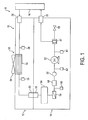
- Fig. 1 is a schematic representation of a modular pumped loop cooling system 8 which includes a modular pump loop cooling apparatus 10 including a cooling module 12 defining a cooling portion of a loop, a pumping module 14 defining a pumping portion of the loop, and a heat exchanger 16, such as a heat sink or cold plate completes the loop.
- the pumping module 14 has an inlet portion, such as inlet coupling 18 for mating with a corresponding outlet portion, such as outlet coupling 20 of the cooling module 12 when the cooling module is placed on top of the pumping module 14.
- the cooling module 12 and pumping modules 14 may be oriented in other suitable orientations, such as a side by side orientation.
- the inlet and outlet couplings 18 and 20 may be male/female couplings that mate with one another automatically during placement of the cooling module 12 on top of the pumping module 14, may be couplings that are coupled in another suitable way, such as by manually threading the couplings, etc.
- the pumping module 14 also has an outlet portion, such as an outlet coupling 22 for connecting to the heat sink 16, which is in thermal contact with a heat source for absorbing heat from the source.
- the cooling module 12 also has an inlet portion, such as an inlet coupling 26 for connecting to the heat sink 16.
- the cooling module 12 is provided to reject heat absorbed by a two-phase fluid, such as a two-phase refrigerant, entering the cooling module and to condense the two-phase fluid to a liquid.
- the cooling module 12 includes a condenser assembly 30 downstream of the inlet coupling 26.
- the condenser assembly 30 includes a condenser 32 that condenses the two-phase fluid and a fan 34 that rejects the heat from the two-phase fluid.
- the condenser assembly 30 may include the condenser 32 and a liquid cooling assembly (not shown), such as a water cooling assembly, for passing liquid across the condenser 32 to cool the two-phase fluid.
- the cooling module 12 also includes charge ports 36 and 38 upstream and downstream of the cooling module 12, respectively, for gauging system pressure, evacuating the system, and/or adding fluid to the system.
- the pumping module 14 is provided to receive the liquid from the cooling module 12 and to pump the liquid to the heat sink 16. To do so, the pumping module includes a reservoir 50 that is fluidically coupled to the condenser 32 for receiving the cooled liquid, and a pump 52 that is fluidically coupled to the reservoir 50 and configured to pump the liquid to the outlet coupling 22.
- the pumping module also includes a strainer 54 for filtering debris, a sight glass 56 for checking if the pump is cavitating, a filter dryer 57 for removing moisture, a pressure relief valve 58 for relieving pressure above a predetermined amount, charge port 60 between the strainer and ball valve, charge ports 62 and 64 upstream and downstream of the pump 52, and the ball valve 66 between the charge ports 60 and 62.
- the cooling apparatus 10 is described in detail with reference to Figs. 2 to 17 .
- the cooling apparatus 10 is shown as a standalone unit separate from the heat sink 16. In this way, the cooling apparatus 10 can be coupled to any one of a plurality of heat sinks having different heat loads.
- the cooling apparatus 10 is therefore scalable to accommodate a wide range of cooling applications so that the apparatus does not have to be redesigned to accommodate a particular system.
- the cooling module 12 is described with reference to Figs. 6 to 12 . It includes the condenser assembly 30, which may be a microchannel coil, and a housing 72 in which the condenser 32 and at least a portion of the fan 34 are disposed.
- the housing 72 includes a bottom portion 74, a top portion 76, a plurality of support portions 78 disposed between the top and bottom portions, and a plurality of side portions 80 ( Fig. 2 ) extending between the support portions 78.
- the portions 74 to 80 can be coupled in any suitable manner, such as by suitable fasteners.
- An opening 82 is provided in the top portion 76 through which the fan 34 extends.
- the fan 34 draws in air through the plurality of side portions 80, which may include perforations 84 ( Fig. 2 ) for allowing the air into the housing 72, and blows the air over sides of the condenser 32.
- the housing 72 is substantially rectangular in shape, and air is drawn into the four sides of the housing 72 and blown over the sides of the condenser 32, although the housing 72 may be any suitable shape.
- the condenser 32 which may be formed in any suitable shape, such as a substantially rectangular shape, is open at a corner at ends 90 and 92.
- inlet and outlet conduits 94 and 96 are provided at the ends 90 and 92.
- the conduits may be provided on the other of the ends or on both ends.
- Coupled to the inlet conduit 94 is the inlet coupling 26 and coupled to the outlet conduit 96 is the outlet coupling 20.
- the conduits may be coupled to the couplings in any suitable manner.
- An opening 98 ( Fig. 2 ) is provided in one of the side portions 80 through which the inlet coupling 26 extends to allow for connection to a corresponding outlet coupling of the heat sink 16.
- the inlet coupling 26 may be supported by a support plate 100 coupled to the bottom and top portions 74 and 76.
- the support plate 100 includes an opening 104 through which the inlet coupling 26 extends.
- Seals 102 such as foam rubber seams may be provided to prevent air from by-passing the condenser 32.
- a washer 106 such as a lock washer, and a nut 108 are connected to the coupling 26 on either side of the opening 104 to hold the coupling 26 and inlet conduit 94 in position.
- An opening is provided in the bottom portion 74 through which the outlet coupling 20 extends.
- a washer 112 such as a lock washer, and a nut 114 ( Fig. 9 ) are coupled to the coupling 20 on either side of the opening to hold the coupling 20 in position.
- One or more openings may also be provided on the bottom and top portions 74 and 76 for electrical wiring. Extending through the openings are respective fittings 116 and 118 ( Fig. 9 ) that are held in position by respective nuts.
- the fittings 118 may be provided for the electrical wiring of the fan 34 to extend through and the fittings 116 may be provided for the electrical wiring of the condenser 32 and fan 34 to extend through to a power box in the pumping module 14.
- the pumping module 14 is described with reference to Figs. 13 to 17 . It includes the reservoir 50, such as a liquid receiver configured to varying volumes of the liquid in the system, the pump 52, which may be any suitable pump such as a gear pump, and a housing 130 in which the reservoir 50 and the pump 52 are disposed.
- the housing 130 includes a bottom portion 132, a plurality of support portions 134 extending upward from the bottom portion 132, and a plurality of side portions 136 ( Fig. 2 ) extending between the support portions 134.
- the side portions 136 may include one or more vents 137 ( Fig. 2 ) for allowing air to escape the housing 130.
- the portions 132 to 136 may be coupled in any suitable manner, such as by suitable fasteners.
- top portion is not shown, it will be appreciated that a top portion may be provided that couples to tops of the support portions 134.
- a top portion may be provided that couples to tops of the support portions 134.
- a plurality of brackets are coupled to the bottom portion 132 in any suitable manner, such as by suitable fasteners, for supporting the various components housed in the housing 130 and for coupling the components to the housing.
- a plurality of brackets 140 are provided for coupling to the reservoir 50
- a bracket 142 is provided for coupling to the pump 52
- a bracket 144 is provided for coupling to the filter dryer 56
- a bracket 146 is provided for coupling to the ball valve 66
- brackets 148 are provided for coupling to an optional electrical enclosure (not shown)
- bracket 150 is provided for coupling to a t-adaptor 152 that is coupled to the filter dryer 56 and the pressure relief valve 58.
- the reservoir 50 includes a sight glass 158 for viewing the fluid in the reservoir, an inlet 160 coupled to an inlet conduit 162, and an outlet 164 coupled to an outlet conduit 166.
- the inlet conduit 162 is coupled to the inlet coupling 18, and the outlet conduit 166 is coupled to an end of the strainer 54.
- Coupled to another end of the strainer 54 is a conduit 168 that is coupled to an inlet 170 of the ball valve 66, and coupled to an outlet 172 of the ball valve 66 is a fluid conduit 174 coupled to an end of the sight glass 56.
- Coupled to another end of the sight glass is a conduit 176 that is coupled to an outlet coupling 178.
- the output coupling 178 is coupled to an inlet coupling 180 of the pump 52 to deliver liquid from the reservoir to the pump. Coupled to an outlet coupling 182 of the pump is a coupling 184, which is coupled to a fluid conduit 186.
- the fluid conduit 186 is coupled to an inlet 188 of the filter dryer 57, and a fluid conduit 190 is coupled to an outlet 192 of the filter dryer 57.
- the outlet 192 of the filter dryer 57 is coupled to an inlet 194 of the pressure relief valve 58, and coupled to an outlet 196 of the pressure relief valve 58 is a fluid conduit 198.
- the fluid conduit 198 is coupled to the outlet coupling 22 that connects to the heat sink 16.
- the above described couplings may be any suitable couplings, such as male/female couplings that mate with one another automatically, and the components may be coupled in any suitable manner.
- an opening is provided in one of the side portions 136 through which the outlet coupling 22 extends.
- a washer such as a lock washer, and a nut 210 are connected to the coupling 22 on either side of the opening to hold the coupling 22 in position.
- the cooling module 12 is placed on top of the pumping module 14 so that the outlet coupling 20 of the cooling module 12 mates with the corresponding input coupling 18 of the pumping module 14.
- openings at the bottom of the bottom portion 74 and support portions 78 align with openings at the top of the support portions 134.
- Suitable fasteners may be inserted through the openings to couple the cooling module 12 to the pumping module 14.
- the side portions 80 and/or side portions 136 can be removed to allow access to the supports 78 and 134.
- fluid is directed through the heat sink 16, and the fluid boils to a part liquid and part vapor mixture as it absorbs heat from the heat source.
- the two-phase fluid mixture then flows to the cooling apparatus 10, where it enters the cooling module 12 via the inlet coupling 26.
- the mixture flows through the coupling 26 to the fluid conduit 94, where it enters the condenser 32.
- the fan 34 draws air into the housing 72 through the perforations 84 in the side portions 80 so that the air flows across the condenser 32 cooling the mixture.
- the condenser 32 then condenses the mixture to a sub-cooled liquid and the fan 34 rejects the heat to the environment.
- the liquid then exits the condenser 32 through the fluid conduit 96 and flows to the outlet coupling 20 coupled to the inlet coupling 18 of the pumping module 14.
- the liquid flows through the couplings 18 and 20 to the fluid conduit 162 and then into the reservoir 50, which acts as a storage tank to compensate for varying volumes of the liquid in the system 8.
- the liquid then exits the reservoir 50 through the fluid conduit 166 and flows to the strainer 54 where it is filtered.
- the fluid exits the strainer 54 and flows through the fluid conduit 168 and through the ball valve 66 when the valve is open.
- the fluid flows through the valve to the fluid conduit 174, flows through the sight glass 56 to the fluid conduit 176, and then flows through the conduit 176 and coupling 178 to the inlet coupling 180 of the pump 52.
- the pump then directs the liquid through the outlet coupling 182 coupled to the coupling 184 and then through the fluid conduit 186 to the filter dryer 57 that removes moisture.
- the fluid exits the filter dryer 57 and flows through the fluid conduit 190, through the t-adaptor 152, and then through the fluid conduit 198 to the outlet coupling 22 that is coupled to the heat sink 16 to provide the liquid to the heat sink for cooling.
Landscapes
- Engineering & Computer Science (AREA)
- Mechanical Engineering (AREA)
- Physics & Mathematics (AREA)
- Thermal Sciences (AREA)
- General Engineering & Computer Science (AREA)
- Life Sciences & Earth Sciences (AREA)
- Sustainable Development (AREA)
- Cooling Or The Like Of Electrical Apparatus (AREA)
- Cooling Or The Like Of Semiconductors Or Solid State Devices (AREA)
Abstract
Description
- The present invention relates generally to cooling systems, and more particularly to pumped liquid cooling systems.
- Power electronic devices, such as IGBTs, SCRs, etc., can achieve high power switching capacity in a small envelope. However, the power electronic devices generate heat during operation, and therefore a cooling system is used to cool the power electronic devices. For example, air may be blown over the power electronic devices or a water-based fluid may be circulated through a cold plate coupled to the power electronic devices to cool the devices.
- The present invention provides a modular pumped loop cooling apparatus including a cooling module and a pumping module, wherein the pumping module has an inlet coupling for mating with a corresponding outlet coupling of the cooling module when the cooling module is placed on top of the pumping module. The modular pumped loop cooling apparatus is provided as a standalone unit that can be coupled to any one of a plurality of heat sinks having different heat loads. The cooling apparatus is therefore scalable to accommodate a wide range of cooling applications so that the apparatus does not have to be redesigned to accommodate a particular system.
- The invention provides a modular pumped loop cooling apparatus which includes a cooling module that rejects heat absorbed by a two-phase fluid entering the cooling module and that condenses the two-phase fluid to a liquid, and a pumping module that receives the liquid from the cooling module and pumps the liquid to a heat sink, wherein the pumping module has an inlet coupling for mating with a corresponding outlet coupling of the cooling module when the cooling module is placed on top of the pumping module.
- Optionally, the couplings mate with one another automatically during placement of the cooling module on top of the pumping module.
- Optionally, the cooling module includes an inlet portion for connecting to the heat sink and the pumping module includes an outlet portion for connecting to the heat sink.
- Optionally, the cooling module defines a cooling portion of a loop and the pumping module defines a pumping portion of the loop, and wherein the loop is completed by the heat sink.
- Optionally, the cooling module includes a housing and a condenser assembly disposed in the housing, the condenser assembly including an inlet conduit and an inlet coupling for connecting to the heat sink and an outlet conduit and the outlet coupling.
- Optionally, the pumping module includes a reservoir having an inlet conduit and the inlet coupling that mates with the outlet coupling of the cooling module, a pump fluidically coupled to the reservoir and including an outlet conduit and an outlet coupling for connecting to the heat sink, and a housing that houses the reservoir and the pump.
- Optionally, the housing has a base portion, a plurality of support portions extending from the base portion, and a plurality of side portions coupled to the support portions, and wherein a plurality of brackets are coupled to the base portion for supporting the reservoir and the pump.
- Optionally, one of the plurality of side portions includes an opening through which the outlet coupling coupled to the pump outlet conduit extends.
- Optionally, the condenser assembly includes a condenser that condenses the two-phase fluid and a fan that rejects the heat.
- Optionally, the fan extends through an opening in the housing on top of the housing and is configured to draw air into a plurality of sides of the housing to cool the two-phase fluid in the condenser and reject the heat to an environment outside of the housing.
- Optionally, the plurality of sides of the housing have perforations for allowing the air to be drawn into the housing and blown over corresponding sides of the condenser.
- Optionally, one of the plurality of side portions includes an opening through which the inlet coupling of the condenser assembly extends.
- Optionally, the housing and condenser are substantially rectangular in shape.
- Optionally, the condenser assembly includes a condenser that condenses the two-phase fluid and a liquid cooling assembly for passing liquid across the condenser to cool the fluid.
- Optionally, the pumped loop cooling apparatus may be provided in combination with any one of a plurality of heat sinks having different heat loads and being configured to be in thermal contact with a heat source, wherein the cooling module includes an inlet portion connected to one of the plurality of heat sinks and the pumping module includes an outlet portion connected to one of the plurality of heat sink.
- The invention also provides a modular pumped loop apparatus configured to be coupled to a heat sink, the apparatus including a cooling module including a housing and a condenser assembly disposed in the housing and including an inlet conduit coupled and an inlet coupling for connecting to the heat sink and an outlet conduit and an outlet coupling, the condenser assembly being configured to reject heat absorbed by a two-phase fluid that enters the condenser assembly through the inlet conduit and condense the two-phase fluid to a liquid, and a pumping module configured to be coupled to the cooling module, the pumping module including a reservoir having an inlet conduit and an inlet coupling for mating with the outlet coupling of the condenser assembly to receive the liquid from the condenser assembly, a pump fluidically coupled to the reservoir for receiving the liquid and including an outlet conduit and an outlet coupling for connecting to the heat sink, and a housing that houses the reservoir and the pump.
- Optionally, the condenser assembly includes a condenser that condenses the two-phase fluid and one of a fan or a liquid cooling assembly for rejecting heat from the fluid.
- Optionally, the inlet coupling of the pumping module mates with the outlet coupling of the cooling module when the cooling module is placed on top of the pumping module.
- Optionally, the pumped loop cooling apparatus may be provided in combination with any one of a plurality of heat sinks having different heat loads and being configured to be in thermal contact with a heat source, wherein the cooling module includes an inlet portion connected to one of the plurality of heat sinks and the pumping module includes an outlet portion connected to one of the plurality of heat sink.
- The invention also provides a method of assembling a pumped loop cooling apparatus which includes providing a cooling module having an input mating coupling for connecting to a first mating coupling on any one of a plurality of heat sinks having different heat loads, providing a pumping module having an output mating coupling for connecting to a second mating coupling on any one of the plurality of heat sinks, and placing the cooling module on top of the pumping module such that an output mating coupling of the cooling module mates with a corresponding input mating coupling of the pumping module to fluidly couple the cooling module and the pumping module.
- The invention is described below by way of example with reference to the accompanying drawings, in which
-
Fig. 1 is a schematic representation of a modular pumped loop cooling system. -
Fig. 2 is a perspective view of a modular pumped loop cooling apparatus of the system. -
Fig. 3 is a top view of the modular pumped loop cooling apparatus. -
Fig. 4 is a left side view of the modular pumped loop cooling apparatus. -
Fig. 5 is a front view of the modular pumped loop cooling apparatus. -
Fig. 6 is a perspective view of an exemplary cooling module of the modular pumped loop cooling apparatus with side portions removed. -
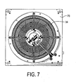
Fig. 7 is a top view of the cooling module. -
Fig. 8 is a front view of the cooling module. -
Fig. 9 is a left side view of the cooling module. -
Fig. 10 is another perspective view of the cooling module. -
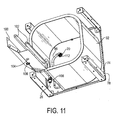
Fig. 11 is a top perspective view of the cooling module. -
Fig. 12 is a perspective view of an exemplary condenser of the cooling module. -
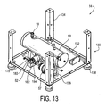
Fig. 13 is a perspective view of an exemplary pumping module with side portions removed. -
Fig. 14 is a perspective view of an exemplary housing of the pumping module. -
Fig. 15 is a top view of the housing. -
Fig. 16 is a perspective view of an exemplary filter dryer and relief valve of the pumping module. -
Fig. 17 is a perspective view of an exemplary reservoir, strainer and ball valve of the pumping module. -
Fig. 18 is a side view of the reservoir, strainer and ball valve. - Turning now in detail to the drawings,
Fig. 1 is a schematic representation of a modular pumpedloop cooling system 8 which includes a modular pumploop cooling apparatus 10 including acooling module 12 defining a cooling portion of a loop, apumping module 14 defining a pumping portion of the loop, and aheat exchanger 16, such as a heat sink or cold plate completes the loop. Thepumping module 14 has an inlet portion, such asinlet coupling 18 for mating with a corresponding outlet portion, such asoutlet coupling 20 of thecooling module 12 when the cooling module is placed on top of thepumping module 14. Alternatively, it will be appreciated that thecooling module 12 andpumping modules 14 may be oriented in other suitable orientations, such as a side by side orientation. The inlet andoutlet couplings cooling module 12 on top of thepumping module 14, may be couplings that are coupled in another suitable way, such as by manually threading the couplings, etc. Thepumping module 14 also has an outlet portion, such as anoutlet coupling 22 for connecting to theheat sink 16, which is in thermal contact with a heat source for absorbing heat from the source. Thecooling module 12 also has an inlet portion, such as aninlet coupling 26 for connecting to theheat sink 16. - The
cooling module 12 is provided to reject heat absorbed by a two-phase fluid, such as a two-phase refrigerant, entering the cooling module and to condense the two-phase fluid to a liquid. To do so, thecooling module 12 includes acondenser assembly 30 downstream of theinlet coupling 26. In an embodiment, thecondenser assembly 30 includes acondenser 32 that condenses the two-phase fluid and afan 34 that rejects the heat from the two-phase fluid. Alternatively, thecondenser assembly 30 may include thecondenser 32 and a liquid cooling assembly (not shown), such as a water cooling assembly, for passing liquid across thecondenser 32 to cool the two-phase fluid. Thecooling module 12 also includescharge ports cooling module 12, respectively, for gauging system pressure, evacuating the system, and/or adding fluid to the system. - The
pumping module 14 is provided to receive the liquid from thecooling module 12 and to pump the liquid to theheat sink 16. To do so, the pumping module includes areservoir 50 that is fluidically coupled to thecondenser 32 for receiving the cooled liquid, and apump 52 that is fluidically coupled to thereservoir 50 and configured to pump the liquid to theoutlet coupling 22. The pumping module also includes astrainer 54 for filtering debris, asight glass 56 for checking if the pump is cavitating, afilter dryer 57 for removing moisture, apressure relief valve 58 for relieving pressure above a predetermined amount,charge port 60 between the strainer and ball valve,charge ports pump 52, and theball valve 66 between thecharge ports - The
cooling apparatus 10 is described in detail with reference toFigs. 2 to 17 . Referring initially toFigs. 2 to 5 , thecooling apparatus 10 is shown as a standalone unit separate from theheat sink 16. In this way, thecooling apparatus 10 can be coupled to any one of a plurality of heat sinks having different heat loads. Thecooling apparatus 10 is therefore scalable to accommodate a wide range of cooling applications so that the apparatus does not have to be redesigned to accommodate a particular system. - The
cooling module 12 is described with reference toFigs. 6 to 12 . It includes thecondenser assembly 30, which may be a microchannel coil, and ahousing 72 in which thecondenser 32 and at least a portion of thefan 34 are disposed. Thehousing 72 includes abottom portion 74, atop portion 76, a plurality ofsupport portions 78 disposed between the top and bottom portions, and a plurality of side portions 80 (Fig. 2 ) extending between thesupport portions 78. Theportions 74 to 80 can be coupled in any suitable manner, such as by suitable fasteners. - An
opening 82 is provided in thetop portion 76 through which thefan 34 extends. Thefan 34 draws in air through the plurality ofside portions 80, which may include perforations 84 (Fig. 2 ) for allowing the air into thehousing 72, and blows the air over sides of thecondenser 32. In the device shown in the drawings, thehousing 72 is substantially rectangular in shape, and air is drawn into the four sides of thehousing 72 and blown over the sides of thecondenser 32, although thehousing 72 may be any suitable shape. - As best shown in
Figs. 10 to 12 , thecondenser 32, which may be formed in any suitable shape, such as a substantially rectangular shape, is open at a corner at ends 90 and 92. Provided at theends outlet conduits inlet conduit 94 is theinlet coupling 26 and coupled to theoutlet conduit 96 is theoutlet coupling 20. The conduits may be coupled to the couplings in any suitable manner. An opening 98 (Fig. 2 ) is provided in one of theside portions 80 through which theinlet coupling 26 extends to allow for connection to a corresponding outlet coupling of theheat sink 16. - The
inlet coupling 26 may be supported by asupport plate 100 coupled to the bottom andtop portions support plate 100 includes anopening 104 through which theinlet coupling 26 extends.Seals 102, such as foam rubber seams may be provided to prevent air from by-passing thecondenser 32. Awasher 106, such as a lock washer, and anut 108 are connected to thecoupling 26 on either side of theopening 104 to hold thecoupling 26 andinlet conduit 94 in position. - An opening is provided in the
bottom portion 74 through which theoutlet coupling 20 extends. Awasher 112, such as a lock washer, and a nut 114 (Fig. 9 ) are coupled to thecoupling 20 on either side of the opening to hold thecoupling 20 in position. One or more openings may also be provided on the bottom andtop portions respective fittings 116 and 118 (Fig. 9 ) that are held in position by respective nuts. Thefittings 118 may be provided for the electrical wiring of thefan 34 to extend through and thefittings 116 may be provided for the electrical wiring of thecondenser 32 andfan 34 to extend through to a power box in thepumping module 14. - The
pumping module 14 is described with reference toFigs. 13 to 17 . It includes thereservoir 50, such as a liquid receiver configured to varying volumes of the liquid in the system, thepump 52, which may be any suitable pump such as a gear pump, and ahousing 130 in which thereservoir 50 and thepump 52 are disposed. Thehousing 130 includes abottom portion 132, a plurality ofsupport portions 134 extending upward from thebottom portion 132, and a plurality of side portions 136 (Fig. 2 ) extending between thesupport portions 134. Theside portions 136 may include one or more vents 137 (Fig. 2 ) for allowing air to escape thehousing 130. Theportions 132 to 136 may be coupled in any suitable manner, such as by suitable fasteners. Although a top portion is not shown, it will be appreciated that a top portion may be provided that couples to tops of thesupport portions 134. Provided at a bottom side of thebottom portion 132 are a plurality offeet 138 for leveling theapparatus 10 and for elevating the apparatus off the ground. - As best shown in
Figs. 14 and15 , a plurality of brackets are coupled to thebottom portion 132 in any suitable manner, such as by suitable fasteners, for supporting the various components housed in thehousing 130 and for coupling the components to the housing. For example, a plurality ofbrackets 140 are provided for coupling to thereservoir 50, abracket 142 is provided for coupling to thepump 52, abracket 144 is provided for coupling to thefilter dryer 56, abracket 146 is provided for coupling to theball valve 66,brackets 148 are provided for coupling to an optional electrical enclosure (not shown), andbracket 150 is provided for coupling to a t-adaptor 152 that is coupled to thefilter dryer 56 and thepressure relief valve 58. - Referring now to
Figs 13 and16 to 18 , thereservoir 50 includes asight glass 158 for viewing the fluid in the reservoir, aninlet 160 coupled to aninlet conduit 162, and anoutlet 164 coupled to anoutlet conduit 166. Theinlet conduit 162 is coupled to theinlet coupling 18, and theoutlet conduit 166 is coupled to an end of thestrainer 54. Coupled to another end of thestrainer 54 is aconduit 168 that is coupled to aninlet 170 of theball valve 66, and coupled to anoutlet 172 of theball valve 66 is afluid conduit 174 coupled to an end of thesight glass 56. Coupled to another end of the sight glass is aconduit 176 that is coupled to anoutlet coupling 178. - The
output coupling 178 is coupled to aninlet coupling 180 of thepump 52 to deliver liquid from the reservoir to the pump. Coupled to anoutlet coupling 182 of the pump is acoupling 184, which is coupled to afluid conduit 186. Thefluid conduit 186 is coupled to aninlet 188 of thefilter dryer 57, and afluid conduit 190 is coupled to anoutlet 192 of thefilter dryer 57. Theoutlet 192 of thefilter dryer 57 is coupled to aninlet 194 of thepressure relief valve 58, and coupled to anoutlet 196 of thepressure relief valve 58 is afluid conduit 198. Thefluid conduit 198 is coupled to theoutlet coupling 22 that connects to theheat sink 16. The above described couplings may be any suitable couplings, such as male/female couplings that mate with one another automatically, and the components may be coupled in any suitable manner. - To allow the
outlet coupling 22 to connect to a corresponding coupling connected to theheat sink 16, an opening is provided in one of theside portions 136 through which theoutlet coupling 22 extends. A washer, such as a lock washer, and anut 210 are connected to thecoupling 22 on either side of the opening to hold thecoupling 22 in position. - To assembly the pumped
loop cooling apparatus 10, thecooling module 12 is placed on top of thepumping module 14 so that theoutlet coupling 20 of thecooling module 12 mates with thecorresponding input coupling 18 of thepumping module 14. When thecooling module 12 is on top of thepumping module 14, openings at the bottom of thebottom portion 74 andsupport portions 78 align with openings at the top of thesupport portions 134. Suitable fasteners may be inserted through the openings to couple thecooling module 12 to thepumping module 14. To facilitate this connection, theside portions 80 and/orside portions 136 can be removed to allow access to thesupports condenser 32 above thereservoir 50 and pump 52, the condenser is prevented from being flooded with liquid, and allows gravity to assist with liquid/vapor separation. - During operation, fluid is directed through the
heat sink 16, and the fluid boils to a part liquid and part vapor mixture as it absorbs heat from the heat source. The two-phase fluid mixture then flows to thecooling apparatus 10, where it enters thecooling module 12 via theinlet coupling 26. The mixture flows through thecoupling 26 to thefluid conduit 94, where it enters thecondenser 32. As the mixture flows through thecondenser 32, thefan 34 draws air into thehousing 72 through theperforations 84 in theside portions 80 so that the air flows across thecondenser 32 cooling the mixture. Thecondenser 32 then condenses the mixture to a sub-cooled liquid and thefan 34 rejects the heat to the environment. - The liquid then exits the
condenser 32 through thefluid conduit 96 and flows to theoutlet coupling 20 coupled to theinlet coupling 18 of thepumping module 14. The liquid flows through thecouplings fluid conduit 162 and then into thereservoir 50, which acts as a storage tank to compensate for varying volumes of the liquid in thesystem 8. The liquid then exits thereservoir 50 through thefluid conduit 166 and flows to thestrainer 54 where it is filtered. The fluid exits thestrainer 54 and flows through thefluid conduit 168 and through theball valve 66 when the valve is open. The fluid flows through the valve to thefluid conduit 174, flows through thesight glass 56 to thefluid conduit 176, and then flows through theconduit 176 andcoupling 178 to theinlet coupling 180 of thepump 52. The pump then directs the liquid through theoutlet coupling 182 coupled to thecoupling 184 and then through thefluid conduit 186 to thefilter dryer 57 that removes moisture. The fluid exits thefilter dryer 57 and flows through thefluid conduit 190, through the t-adaptor 152, and then through thefluid conduit 198 to theoutlet coupling 22 that is coupled to theheat sink 16 to provide the liquid to the heat sink for cooling.
Claims (15)
- A modular pumped loop cooling apparatus including:a cooling module that rejects heat absorbed by a two-phase fluid entering the cooling module and that condenses the two-phase fluid to a liquid, anda pumping module that receives the liquid from the cooling module and pumps the liquid to a heat sink,wherein the pumping module has an inlet coupling for mating with a corresponding outlet coupling of the cooling module when the cooling module is placed on top of the pumping module.
- The pumped loop apparatus according to claim 1, wherein the couplings mate with one another automatically during placement of the cooling module on top of the pumping module.
- The pumped loop apparatus according to claim 1 or claim 2, wherein the cooling module includes an inlet portion for connecting to the heat sink and the pumping module includes an outlet portion for connecting to the heat sink.
- The pumped loop apparatus according to claim 3, wherein the cooling module defines a cooling portion of a loop and the pumping module defines a pumping portion of the loop, and wherein the loop is completed by the heat sink.
- The pumped loop apparatus according to any one of claims 1 to 4, wherein the cooling module includes a housing and a condenser assembly disposed in the housing, the condenser assembly including an inlet conduit and an inlet coupling for connecting to the heat sink and an outlet conduit and the outlet coupling.
- The pumped loop apparatus according to claim 5, wherein the pumping module includes a reservoir having an inlet conduit and the inlet coupling that mates with the outlet coupling of the cooling module, a pump fluidically coupled to the reservoir and including an outlet conduit and an outlet coupling for connecting to the heat sink, and a housing that houses the reservoir and the pump.
- The pumped loop cooling apparatus according to claim 6, wherein the housing has a base portion, a plurality of support portions extending from the base portion, and a plurality of side portions coupled to the support portions, and wherein a plurality of brackets are coupled to the base portion for supporting the reservoir and the pump.
- The pumped loop cooling apparatus according to claim 7, wherein one of the plurality of side portions includes an opening through which the outlet coupling coupled to the pump outlet conduit extends.
- The pumped loop cooling apparatus according to any one of claims 5 to 8, wherein the condenser assembly includes a condenser that condenses the two-phase fluid and a fan that rejects the heat.
- The pumped loop cooling apparatus according to claim 9, wherein the fan extends through an opening in the housing on top of the housing and is configured to draw air into a plurality of sides of the housing to cool the two-phase fluid in the condenser and reject the heat to an environment outside of the housing.
- The pumped loop cooling apparatus according to claim 10, wherein the plurality of sides of the housing have perforations for allowing the air to be drawn into the housing and blown over corresponding sides of the condenser.
- The pumped loop cooling apparatus according to claim 11, wherein one of the plurality of side portions includes an opening through which the inlet coupling of the condenser assembly extends.
- The pumped loop cooling apparatus according to any one of claims 5 to 8, wherein the condenser assembly includes a condenser that condenses the two-phase fluid and a liquid cooling assembly for passing liquid across the condenser to cool the fluid.
- The pumped loop cooling apparatus according to any one of claims 1 to 13 in combination with any one of a plurality of heat sinks having different heat loads and being configured to be in thermal contact with a heat source, wherein the cooling module includes an inlet portion connected to one of the plurality of heat sinks and the pumping module includes an outlet portion connected to one of the plurality of heat sink.
- A method of assembling a pumped loop cooling apparatus including:providing a cooling module having an input mating coupling for connecting to a first mating coupling on any one of a plurality of heat sinks having different heat loads,providing a pumping module having an output mating coupling for connecting to a second mating coupling on any one of the plurality of heat sinks, andplacing the cooling module on top of the pumping module such that an output mating coupling of the cooling module mates with a corresponding input mating coupling of the pumping module to fluidly couple the cooling module and the pumping module.
Applications Claiming Priority (1)
| Application Number | Priority Date | Filing Date | Title |
|---|---|---|---|
| US13/835,770 US20140262158A1 (en) | 2013-03-15 | 2013-03-15 | Two-phase cooling system |
Publications (2)
| Publication Number | Publication Date |
|---|---|
| EP2778590A2 true EP2778590A2 (en) | 2014-09-17 |
| EP2778590A3 EP2778590A3 (en) | 2015-04-08 |
Family
ID=50238122
Family Applications (1)
| Application Number | Title | Priority Date | Filing Date |
|---|---|---|---|
| EP20140156769 Withdrawn EP2778590A3 (en) | 2013-03-15 | 2014-02-26 | Two-phase cooling system |
Country Status (3)
| Country | Link |
|---|---|
| US (1) | US20140262158A1 (en) |
| EP (1) | EP2778590A3 (en) |
| KR (1) | KR20140113358A (en) |
Families Citing this family (4)
| Publication number | Priority date | Publication date | Assignee | Title |
|---|---|---|---|---|
| AT516942B1 (en) * | 2015-04-28 | 2016-10-15 | Euler-Rolle Thomas Dipl Ing | Cooler station for connection of a liquid cooler |
| JP6635131B2 (en) * | 2018-01-31 | 2020-01-22 | ダイキン工業株式会社 | Air conditioner outdoor unit |
| JP6673376B2 (en) * | 2018-01-31 | 2020-03-25 | ダイキン工業株式会社 | Air conditioner outdoor unit |
| US20230076784A1 (en) * | 2021-09-06 | 2023-03-09 | Inventec (Pudong) Technology Corporation | Heat dissipation assembly and electronic assembly |
Family Cites Families (14)
| Publication number | Priority date | Publication date | Assignee | Title |
|---|---|---|---|---|
| US4138859A (en) * | 1977-11-02 | 1979-02-13 | General Electric Company | Split heat pump outdoor fan arrangement |
| KR910012619A (en) * | 1989-12-28 | 1991-08-08 | 강진구 | Air conditioner |
| US5323847A (en) * | 1990-08-01 | 1994-06-28 | Hitachi, Ltd. | Electronic apparatus and method of cooling the same |
| KR0132997B1 (en) * | 1994-08-20 | 1998-04-21 | 김광호 | Outlet machine of airconditioner |
| DE19711258C2 (en) * | 1997-03-18 | 1999-09-02 | Behr Gmbh & Co | Stacked disc oil cooler |
| WO2001051859A1 (en) * | 2000-01-14 | 2001-07-19 | Toshiba Carrier Corporation | Outdoor unit of air conditioner |
| US20040008483A1 (en) * | 2002-07-13 | 2004-01-15 | Kioan Cheon | Water cooling type cooling system for electronic device |
| US6957547B2 (en) * | 2003-09-17 | 2005-10-25 | Delphi Technologies, Inc. | Variable capacity condensing unit |
| JP4140495B2 (en) * | 2003-09-25 | 2008-08-27 | 株式会社日立製作所 | Cooling module |
| US20070272397A1 (en) * | 2006-05-23 | 2007-11-29 | Ilya Reyzin | Compact liquid cooling unit for high end servers |
| US7466550B2 (en) * | 2006-11-03 | 2008-12-16 | Xigmatek Co., Ltd | Integrated heat dissipating assembly |
| US8651172B2 (en) * | 2007-03-22 | 2014-02-18 | Raytheon Company | System and method for separating components of a fluid coolant for cooling a structure |
| US8931546B2 (en) * | 2010-03-29 | 2015-01-13 | Hamilton Sundstrand Space Sytems International, Inc. | Compact two sided cold plate with threaded inserts |
| US9061382B2 (en) * | 2011-07-25 | 2015-06-23 | International Business Machines Corporation | Heat sink structure with a vapor-permeable membrane for two-phase cooling |
-
2013
- 2013-03-15 US US13/835,770 patent/US20140262158A1/en not_active Abandoned
-
2014
- 2014-02-26 EP EP20140156769 patent/EP2778590A3/en not_active Withdrawn
- 2014-03-04 KR KR1020140025339A patent/KR20140113358A/en not_active Abandoned
Non-Patent Citations (1)
| Title |
|---|
| None |
Also Published As
| Publication number | Publication date |
|---|---|
| US20140262158A1 (en) | 2014-09-18 |
| KR20140113358A (en) | 2014-09-24 |
| EP2778590A3 (en) | 2015-04-08 |
Similar Documents
| Publication | Publication Date | Title |
|---|---|---|
| JP7412064B2 (en) | electronic equipment cooling system | |
| JP6003423B2 (en) | Cooling unit and electronic device | |
| US11083110B2 (en) | Multifunction coolant manifold structures | |
| CA3006594C (en) | Fluid cooling system and method for electronics equipment | |
| US7961475B2 (en) | Apparatus and method for facilitating immersion-cooling of an electronic subsystem | |
| CN103988026B (en) | Heater and possess the outdoor unit of refrigerating plant of this heater | |
| EP3193571B1 (en) | Heat pipe based cooling system and power equipment | |
| US20020166334A1 (en) | Modular liquid-cooled air conditioning system | |
| US20110315343A1 (en) | Interleaved, immersion-cooling apparatuses and methods for cooling electronic subsystems | |
| US20140262158A1 (en) | Two-phase cooling system | |
| USRE50310E1 (en) | Hazardous location cooling system and method for use thereof | |
| CN110345794A (en) | Heat exchanger assembly | |
| CN207778628U (en) | Drain tray and refrigeration cycle device | |
| JP6489211B2 (en) | Heat pump equipment | |
| JPWO2018062054A1 (en) | Refrigeration cycle device | |
| CN103857262B (en) | Container type data center heat dissipation system | |
| JP2019124373A (en) | Heat exchange unit | |
| CN104676775B (en) | A kind of mini air conditioner | |
| US12515149B2 (en) | Liquid cooling system fill kit and method of use | |
| JP2022009385A (en) | Systems and methods for venting enclosure | |
| CN210267787U (en) | Water chiller with multiple water outlets | |
| KR101514246B1 (en) | Air compressor | |
| TWI494529B (en) | Cooling device | |
| CN211120149U (en) | Multi-connected host and multi-connected system | |
| JP2021081138A (en) | Heat source machine for refrigeration cycle device |
Legal Events
| Date | Code | Title | Description |
|---|---|---|---|
| PUAI | Public reference made under article 153(3) epc to a published international application that has entered the european phase |
Free format text: ORIGINAL CODE: 0009012 |
|
| 17P | Request for examination filed |
Effective date: 20140226 |
|
| AK | Designated contracting states |
Kind code of ref document: A2 Designated state(s): AL AT BE BG CH CY CZ DE DK EE ES FI FR GB GR HR HU IE IS IT LI LT LU LV MC MK MT NL NO PL PT RO RS SE SI SK SM TR |
|
| AX | Request for extension of the european patent |
Extension state: BA ME |
|
| PUAL | Search report despatched |
Free format text: ORIGINAL CODE: 0009013 |
|
| AK | Designated contracting states |
Kind code of ref document: A3 Designated state(s): AL AT BE BG CH CY CZ DE DK EE ES FI FR GB GR HR HU IE IS IT LI LT LU LV MC MK MT NL NO PL PT RO RS SE SI SK SM TR |
|
| AX | Request for extension of the european patent |
Extension state: BA ME |
|
| RIC1 | Information provided on ipc code assigned before grant |
Ipc: F28D 15/02 20060101AFI20150303BHEP Ipc: F28D 1/02 20060101ALI20150303BHEP Ipc: H01L 23/427 20060101ALI20150303BHEP |
|
| R17P | Request for examination filed (corrected) |
Effective date: 20150922 |
|
| RBV | Designated contracting states (corrected) |
Designated state(s): AL AT BE BG CH CY CZ DE DK EE ES FI FR GB GR HR HU IE IS IT LI LT LU LV MC MK MT NL NO PL PT RO RS SE SI SK SM TR |
|
| STAA | Information on the status of an ep patent application or granted ep patent |
Free format text: STATUS: THE APPLICATION HAS BEEN WITHDRAWN |
|
| 18W | Application withdrawn |
Effective date: 20160331 |